![Lab 352 Answers [PDF]](https://pdfs.asia/img/200x200/lab-352-answers.jpg)
34 0 197 KB
Activity 3.5.2: Subnetting Scenario 1 (answers) Topology Diagram
Addressing Table Device
Interface
IP Address
Subnet Mask
Default Gateway
Fa0/0
192.168.9.129
255.255.255.224
N/A
S0/0/0
192.168.9.161
255.255.255.224
N/A
S0/0/1
192.168.9.97
255.255.255.224
N/A
Fa0/0
192.168.9.193
255.255.255.224
N/A
Fa0/1
192.168.9.1225
255.255.255.224
N/A
S0/0/0
192.168.9.190
255.255.255.224
N/A
Fa0/0
192.168.9.65
255.255.255.224
N/A
Fa0/1
192.168.9.33
255.255.255.224
N/A
S0/0/1
192.168.9.126
255.255.255.224
N/A
PC1
NIC
192.168.9.158
255.255.255.224
192.168.9.129
PC2
NIC
192.168.9.222
255.255.255.224
192.168.9.193
PC3
NIC
192.168.9.254
255.255.255.224
192.168.9.225
PC4
NIC
192.168.9.94
255.255.255.224
192.168.9.65
PC5
NIC
192.168.9.62
255.255.255.224
192.168.9.33
HQ
BRANCH1
BRANCH2
Learning Objectives Upon completion of this lab, you will be able to: •
Determine the number of subnets needed.
•
Determine the number of hosts needed.
•
Design an appropriate addressing scheme.
Copyright 2007, Cisco Systems, Inc.
Routing Protocols and Concepts v1.0 –Activity 3.5.2
1 of 3
•
Assign addresses and subnet mask pairs to device interfaces and hosts.
•
Examine the use of the available network address space.
•
Determine how static routing could be applied to the network.
Scenario In this lab, you have been given the network address 192.168.9.0/24 to subnet and provide the IP addressing for the network shown in the Topology Diagram. The network has the following addressing requirements: •
The BRANCH1 LAN 1 will require 10 host IP addresses.
•
The BRANCH1 LAN 2 will require 10 host IP addresses.
•
The BRANCH2 LAN 1 will require 10 host IP addresses.
•
The BRANCH2 LAN 2 will require 10 host IP addresses.
•
The HQ LAN will require 20 host IP addresses.
•
The link from HQ to BRANCH1 will require an IP address for each end of the link.
•
The link from HQ to BRANCH2 will require an IP address for each end of the link.
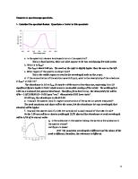
Task 1: Examine the Network Requirements. Examine the network requirements and answer the questions below. Keep in mind that IP addresses will be needed for each of the LAN interfaces. How many subnets are needed? _____7_____ What is the maximum number of IP addresses that are needed for a single subnet? _____21_____ How many IP addresses are needed for each of the branch LANs? _____11_____ What is the total number of IP addresses that are needed? _____69_____
Task 2: Design an IP Addressing Scheme. Step 1: Subnet the 192.168.9.0 network into the appropriate number of subnets. What will the subnet mask be for the subnetworks? _____________255.255.255.224 or /27_____________ How many usable host IP addresses are there per subnet? _____30_____ Fill in the following chart with the subnet information. Subnet Number 0 1 2 3 4 5 6 7
Subnet Address 192.168.9.0 192.168.9.32 192.168.9.64 192.168.9.96 192.168.9.128 192.168.9.160 192.168.9.192 192.168.9.224
First Usable Host Address 192.168.9.1 192.168.9.33 192.168.9.65 192.168.9.97 192.168.9.129 192.168.9.161 192.168.9.193 192.168.9.225
Last Usable Host Address 192.168.9.30 192.168.9.62 192.168.9.94 192.168.9.126 192.168.9.158 192.168.9.190 192.168.9.222 192.168.9.254
Broadcast Address 192.168.9.31 192.168.9.63 192.168.9.95 192.168.9.127 192.168.9.159 192.168.9.191 192.168.9.223 192.168.9.255
Step 2: Assign the subnets to the network shown in the Topology Diagram. When assigning the subnets, keep in mind that routing will need to occur to allow information to be sent throughout the network. The subnets will be assigned to the networks to allow for route summarization on each of the routers. Copyright 2007, Cisco Systems, Inc.
Routing Protocols and Concepts v1.0 – Activity 3.5.2
2 of 3
1. Assign subnet 1 to the BRANCH2 LAN 2: __________192.168.9.32 /27__________ 2. Assign subnet 2 to BRANCH2 LAN 1 subnet address: __________192.168.9.64 /27__________ 3. Assign subnet 3 to link from HQ to BRANCH2 subnet address: __________192.168.9.96 /27__________ 4. Assign subnet 4 to HQ LAN subnet address: __________192.168.9.128 /27__________ 5. Assign subnet 5 to link from HQ to BRANCH1 subnet address: __________192.168.9.160 /27__________ 6. Assign subnet 6 to BRANCH1 LAN 2 subnet address: __________192.168.9.192 /27__________ 7. Assign subnet 7 to BRANCH1 LAN 1 subnet address: __________192.168.9.224 /27__________
Task 3: Assign IP Addresses to the Network Devices Assign the appropriate addresses to the device interfaces. Document the addresses to be used in the Addressing Table provided under the Topology Diagram. Step 1: Assign addresses to the HQ router. 1. Assign the first valid host address in the HQ LAN subnet to the LAN interface. 2. Assign the first valid host address in link from HQ to BRANCH1 subnet to the S0/0/0 interface. 3. Assign the first valid host address in link from HQ to BRANCH2 subnet to the S0/0/1 interface. Step 2: Assign addresses to the BRANCH1 router. 1. Assign the first valid host address in the BRANCH1 LAN 1 subnet to the Fa0/0 LAN interface. 2. Assign the first valid host address in the BRANCH1 LAN 2 subnet to the Fa0/1 LAN interface. 3. Assign the last valid host address in link from HQ to BRANCH1 subnet to the WAN interface. Step 3: Assign addresses to the BRANCH2 router. 1. Assign the first valid host address in the BRANCH2 LAN 1 subnet to the Fa0/0 LAN interface. 2. Assign the first valid host address in the BRANCH2 LAN 2 subnet to the Fa0/1 LAN interface. 3. Assign the last valid host address in link from HQ to BRANCH2 subnet to the WAN interface. Step 4: Assign addresses to the host PCs. 1. Assign the last valid host address in the HQ LAN subnet to PC1. 2. Assign the last valid host address in the BRANCH1 LAN 1 subnet to PC2. 3. Assign the last valid host address in the BRANCH1 LAN 2 subnet to PC3. 4. Assign the last valid host address in the BRANCH2 LAN 1 subnet to PC4. 5. Assign the last valid host address in the BRANCH2 LAN 2 subnet to PC5.
Copyright 2007, Cisco Systems, Inc.
Routing Protocols and Concepts v1.0 – Activity 3.5.2
3 of 3