![PDF At115 2002 Nouvo [PDF]](https://pdfs.asia/img/200x200/pdf-at115-2002-nouvo.jpg)
14 0 33 MB
AT115
SERVICEMANUAL 5MX-F8197-E0
EAS00000
AT115 SERVICE MANUAL ©2002 by Yamaha Yamaha Motor Co., Ltd. First edition, January 2002 All rights reserved. Any reproduction or unauthorized use without the written permission of Yamaha Motor Co., Ltd. is expressly prohibited.
EAS00002
NOTICE This manual was produced by the Yamaha Motor Company, Ltd. primarily for use by Yamaha dealers and their qualified mechanics. It is not possible to include all the knowledge of a mechanic in one manual. Therefore, anyone who uses this book to perform maintenance and repairs rep airs on Yamaha vehicles should have a basic understanding of mechanics and the techniques to repair these types of vehicles. Repair and maintenance work attempted by anyone without this knowledge is likely to render the vehicle unsafe and unfit for use. Yamaha Motor Company, Ltd. is continually striving to improve all of its models. Modifications and significant changes in specifications or procedures will be forwarded to all authorized Yamaha dealers and will appear in future editions of this manual where applicable. NOTE: Designs and specifications are subject to change without notice. _
EAS00004
IMPORTANT MANUAL INFORMATION Particularly important information is distinguished in this manual by the following. The Safety Alert Symbol means ATTENTION! BECOME ALERT! YOUR SAFETY IS INVOLVED!
WARNING
CAUTION: NOTE:
Failure to follow WARNING instructions could result in severe injury or death to the motorcycle operator, a bystander or a person checking or repairing the motorcycle. A CAUTION indicates special precautions that must be taken to avoid damage to the motorcycle. A NOTE provides key information to make procedures easier or clearer.
EASF0007
HOW TO USE THIS MANUAL CONSTRUCTION OF THIS MANUAL This manual consists of chapters for the main categories of subjects. (See “Illustrated symbols”) 1st title 1:
This is a chapter with its symbol on the upper right of each page.
2nd title 2:
This title appears on the upper of each page on the left of the chapter symbol. (For the chapter “Periodic checks and adjustments” the 3rd title appears.)
3rd title 3:
This is a final title.
MANUAL FORMAT All of the procedures in this manual are organized in a sequential, step-by-step fformat. ormat. The information has been compiled to provide the mechanic with an easy to read, handy reference that contains comprehensive explanations of all disassembly, repair, assembly, and inspections. A set of particularly important procedure 4 is placed between a line of triangle “” with each procedure preceded by “”. IMPROTANT FEATURES Data and a special tool are framed in a box preceded by a relevant symbol 5. An encircled numeral 6 indicates a part name, and an encircled alphabetical letter data or an alignment mark 7, the others being indicated by an alphabetical letter in a box 8. A condition of a faulty component will precede an arrow symbol and the course of action required the symbol 9. EXPLODED DIAGRAM Each chapter provides exploded diagrams before each disassembly section for ease in identifying correct disassembly and assembly procedures.
1
EASF0009
2
GEN INFO
SYMBOLS The following symbols are not relevant to every vehicle. Symbols 1 to 8 indicate the subject of each chapter.
SPEC
3
4
CHK ADJ
1 General information 2 Specifications 3 Periodic checks and adjustments 4 Engine 5 Carburetor 6 Chassis 7 Electrical system 8 Troubleshooting
ENG
5
6
CARB
CHAS
7
8 –
ELEC
TRBL SHTG
+
9
Symbols 9 to F indicate the following.
0
9 Serviceable with engine mounted
A
B
C
D
0 Filling fluid A Lubricant B Special tool C Tightening torque D Wear limit, clearance E Engine speed F Electrical data
T R .
.
E
F
G
H
E
Symbols G to L in the exploded diagrams indicate the types of lubricants and lubrication points.
I
G
J
M
K B
L M
LS
M
Symbols M to N in the exploded diagrams indicate the following.
N
LT
G Engine oil H Gear oil I Molybdenum-disulfide oil J Wheel-bearing grease K Lithium-soap-based grease L Molybdenum-disulfide grease
New
M Apply locking agent (LOCTITE ® ) N Replace the part
EASF0011
TABLE OF CONTENTS GENERAL INFORMATION SPECIFICATIONS
GEN INFO
1 2
SPEC
PERIODIC CHECKS AND ADJUSTMENTS
CHK ADJ
3
ENGINE
ENG
4
CARB
5
CHAS
6
CARBURETOR CHASSIS
–
ELECTRICAL SYSTEM TROUBLESHOOTING
+
ELEC
7
TRBL SHTG
8
GEN INFO
CHAPTER 1 GENERAL INFORMATION MOTORCYCLE IDENTIFICATION..................................................................1-1 IDENTIFICATION ..................................................................1-1 VEHICLE IDENTIFICATION NUMBER ..................................................... ..................................... ................ 1-1 ENGINE SERIAL NUMBER ...................................................................... ........................................ .............................. 1-1 FEATURES ......................................................................................................1-2 FEATURES......................................................................................................1-2 V-BELT POWERMATIC ..................................................................... ................................ ............................................ ....... 1-2 TORQUE CAM .......................................................................... .................................... ...................................................... ................ 1-5 IMPORTANT INFORMATION .........................................................................1-6 PREPARATION FOR REMOVAL AND DISASSEMBLY...........................1-6 REPLACEMENT PARTS...........................................................................1-6 GASKETS, OIL SEALS AND O-RINGS .................................................... ................................... ................. 1-6 LOCK WASHERS/PLATES WASHERS/PLATES AND COTTER PINS ..................................... 1-7 BEARINGS AND OIL SEALS .................................................................... ....................................... ............................. 1-7 CIRCLIPS ........................................................................ ................................... ............................................................... .......................... 1-7 CHECKING THE CONNECTIONS ..................................................................1-8 SPECIAL TOOLS ............................................................................................1-9
GEN INFO
MOTORCYCLE IDENTIFICATION
GEN INFO
EAS00014
GENERAL INFORMATION 1
MOTORCYCLE IDENTIFICATION EAS00017
VEHICLE IDENTIFICATION NUMBER The vehicle identification 1 is stamped into the frame.
EASF0016
1
ENGINE SERIAL NUMBER The engine serial number 1 is stamped into the crankcase. NOTE: Designs and specifications are subject to change without notice.
1-1
GEN INFO
FEATURES EAS00019
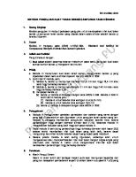
FEATURES V-BELT POWERMATIC Mechanism A variable ratio V-belt transmission, which is fully automatic, has been adopted. To accommodate the engine speed, the optimum transmission ratio is automatically established. In addition, shocks cannot be felt when changing speeds, and smooth acceleration and an excellent climbing power can be achieved. This transmission mechanism consists of a primary pulley and a secondary pulley, which are connected by a V-belt. Also, the reduction ratio changes according to the movement of the V-belt.
1
2 3
4
5
6 7
C
1 Crankshaft 2 Primary sliding sheave 3 Primary pulley weight 4 Main axle 5 Drive axle
B
A 0
6 Secondary fixed sheave 7 Secondary sliding sheave 8 Spring 9 Primary drive gear 0 Clutch housing
1-2
9
8
A Clutch carrier B V-belt C Primary fixed sheave
FEATURES
GEN INFO
Operation 1. Idl Idle e speed speed operati operation on When the engine speed is at idle, power is transmitted from the primary pulley, V-belt, and secondary pulley to the clutch carrier. However, power is not transmitted to the clutch housing because the centrifugal force of the clutch carrier is weaker than the tension of the clutch springs, thus the clutch carrier (shoe) does not come into contact with the clutch housing.
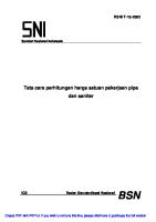
2. St Start artin ing g out out When engine speed reaches approximately 3,000 r/min, the centrifugal force of the clutch carrier becomes stronger than the tension of the clutch springs. This causes the clutch carrier (shoe) to come into contact with the clutch housing and to initiate frictional force (transmission torque). When this occurs, the V-belt moves inward toward the inner diameter of the primary pulley and outward toward the perimeter of the secondary pulley. Also, the reduction ratio is maximized and sufficient driving force is transmitted to the rear wheel. 1
2
Clut Clutch ch--in re revo vollut utio ion n 2, 2,55 550 0 ~ 2, 2,95 950 0 rpm rpm Clutch Clu tch-st -stall all revolut revolution ion 4,700 4,700 ~ 5,300 5,300 rpm rpm
3
1 V-belt 2 Secondary pulley 3 Primary pulley
1-3
FEATURES
GEN INFO
3. Med Medium ium-sp -speed eed operati operation on As engine speed increases, the primary pulley weight is moved outward by centrifugal force. The primary pulley weight pushes the primary sliding sheave towards the primary fixed sheave, which forces the V-belt toward the outer perimeter of the primary pulley. When this occurs, the diameter of the V-belt is increased at the primary pulley. As the diameter of the V-belt increases, the belt is pulled at the secondary pulley because the length of the belt is constant. As a result, the belt is pushed toward the inner diameter of the secondary pulley until the tension of the V-belt and clutch springs is balanced. When this occurs, the diameter of the V-belt is decreased at the secondary pulley and the reduction ratio gradually decreases and the speed of the secondary pulley gradually increases.
4. Hig High-s h-speed peed operati operation on As engine speed increases from medium-speed operation, the primary pulley weight moves further outward, the primary sliding sheave is pushed closer toward the primary fixed sheave, and the V-belt is forced further outward toward the perimeter of the primary pulley. At the secondary pulley the V-belt is forced further inward and, as a result, the reduction ratio is minimized.
1-4
FEATURES
GEN INFO
TORQUE CAM When a powerful torque is needed ne eded to climb hills, powerful climbing power is delivered from the t he operation of the torque cam, not from driving skill of the rider. Operation When the motorcycle approaches a hill, the load of the rear wheel increases and traveling speed is reduced. As the throttle is opened to increase speed, the torque of the engine increases and the secondary sliding sheave forces the V-belt outward toward the perimeter of the secondary pulley. As a result, the diameter of the V-belt increases at the secondary pulley, and at the same time a large driving force, excellent operation, excellent acceleration ability, and powerful climbing capabilities are achieved because the transmission ratio is also increased. Normal operation
Climbing hills or quick acceleration 1
2 4
È
3
É
1 Secondary fixed sheave
È Small load on rear wheel
sliding sheave 2 3 Secondary V-belt 4 Torque cam
É Large load on rear wheel
1-5
3
IMPORTANT INFORMATION
GEN INFO
EAS00020
IMPORTANT INFORMATION PREPARATION FOR REMOVAL AND DISASSEMBLY 1. Before removal removal and disassembly, disassembly, remov remove e all dirt, mud, dust and foreign material. 2. Use only only the proper proper tools and cleaning cleaning equipment. Refer to the “SPECIAL TOOLS” TOOLS”. 3. When disassemb disassembling, ling, alwa always ys keep keep mated parts together. This includes gears, cylinders, pistons and other parts that have been “mated mated”” through normal wear. Mated parts must always be reused or replaced as an assembly. 4. During disassemb disassembly ly,, clean all of the the parts and place them in trays in the order of disassembly. This will speed up assembly and allow for the correct installation of all par ts. 5. Keep Keep all parts away away from from any source source of fire. fire.
EAS00021
REPLACEMENT PARTS Use only genuine Yamaha parts for all replacements. Use oil and grease recommended by Yamaha for all lubrication jobs. Other brands may be similar in function and appearance, but inferior in quality.
EAS00022
GASKETS, OIL SEALS AND O-RINGS 1. When overhaul overhauling ing the engine, engine, replace replace all all gaskets, seals and O-rings. All gasket surfaces, oil seal lips and O-rings must be cleaned. 2. During reassembl reassembly y, properly oil all mating mating parts and bearings and lubricate the oil seal lips with grease.
1-6
IMPORTANT INFORMATION
GEN INFO
EAS00023
LOCK WASHERS/PLATES AND COTTER PINS After removal, replace all lock washers/plates 1 and cotter pins. After the bolt or nut has been tightened to specification, bend the lock tabs along a flat of the bolt or nut.
EAS00024
BEARINGS AND OIL SEALS Install bearings and oil seals so that the manufacturer’’s marks or numbers are visible. When facturer installing oil seals, lubricate the oil seal lips with a light coat of lithium-soap-based grease. Oil bearings liberally when installing, if appropriate. 1 Oil seal _
CAUTION:
Do not spin the bearing with compressed air because this will damage the bearing surfaces. 1 Bearing
EAS00025
CIRCLIPS Before reassembly, check all circlips carefully and replace damaged or distorted circlips. Always replace piston pin clips after one use. When installing a circlip 1, make sure the sharp-edged corner 2 is positioned opposite the thrust 3 that the circlip receives. 4 Shaft
1-7
CHECKING THE CONNECTIONS
GEN INFO
EAS00026
CHECKING THE CONNECTIONS Check the leads, couplers, and connectors for stains, rust, moisture, etc. 1. Disc Disconn onnec ect: t: • lead • coupler • 2. • • •
connector Chec Check: k: lead coupler connector Moisture → Dry with an air blower. Rust/stains → Connect and disconnect several times.
3. Chec Check: k: • all connections Loose connection → Connect properly. NOTE: If the pin 1 on the terminal is flattened, bend it up. _
4. • • •
Conn Connec ect: t: lead coupler connector
NOTE: Make sure all connections are tight. _
5. Chec Check: k: • continuity (with the pocket tester) Pocket tester 90890-03112 NOTE: • If there is no continuity, clean the terminals. • When checking the wire harness, perform steps (1) to (3). • As a quick remedy, use a contact revitalizer available at most part stores. _
1-8
SPECIAL TOOLS
GEN INFO
EAS00027
SPECIAL TOOLS The following special tools are necessary for complete and accurate tune-up and assembly. Use only the appropriate special tools as this will help prevent damage caused by the use of inappropriate tools or improvised techniques. Special tools, part numbers or both may differ depending on the country. When placing an order, refer to the list provided below to avoid any mistakes. Tool No. Weight 90890-01084 Slide hammer bolt 90890-01085
Tool name/Usage Weight Slide hammer bolt
These tools are used when removing or installing the rocker arm shafts. Fork seal driver weight
90890-01184 This tool is used to installing the oil seal. Fork seal driver attachment 90890-01186 This tool is used to installing the oil seal. Flywheel puller 90890-01189 This tool is used for removing the rotor. Rotor holding tool 90890-01235
This tool is used to hold the generator rotor when removing or installing the generator rotor bolt. Valve spring compressor
90890-01253 These tools are used when removing or installing the valve and the valve spring. Ring nut wrench 90890-01268 This tool is used to loosen and tighten the steering ring nut.
1-9
Illustration
SPECIAL TOOLS Tool No.
Tool name/Usage Tappet adjusting tool
90890-01311 This tool is necessary for adjusting valve clearance. Fuel level gauge 90890-01312 This gauge is used to measure the fuel level in the float chamber. T-handle 90890-01326
This tool is used for holding the damper rod holder when removing or installing the damper rod holder. Clutch spring holder
90890-01337 This tool is used to disassembly and assembly the secondary pulley. Locknut wrench 90890-01348
This tool is used to loosen and tighten the clutch carrier locknut of the secondary pulley. Steering nut wrench
90890-01403 This tool is used to loosen and tighten the steering ring nut. Oil seal guide 90890-01384 This tool is used to install oil seals. Sheave holder 90890-01701 This tool is used for holding the secondary pulley.
1 - 10
GEN INFO
Illustration
SPECIAL TOOLS Tool No.
Tool name/Usage Thickness gauge
90890-03079 This tool is used to measure the valve clearance. Compression gauge 90890-03081 These tools are used to measure the engine compression. Pocket tester 90890-03112 These instruments are invaluable for checking the electrical system. Engine tachometer
90890-03113 This tool is needed for detecting engine rpm. Valve guide remover (5 mm) 90890-04097 This tool is needed to remove and install the valve guide. Valve guide installer (5 mm) 90890-04098 This tool is needed to install the valve guide. Valve guide reamer (5 mm) 90890-04099 This tool is needed to rebore the new valve guide. Valve lapper 90890-04101
This tool is used for removing and installing the lifter and for lapping the valve.
1 - 11
GEN INFO
Illustration
SPECIAL TOOLS Tool No.
Tool name/Usage Ignition checker
90890-06754 This instrument is necessary for checking the ignition system components. Yamaha bond No. 1215 90890-85505 This sealant (bond) is used for crankcase mating surface, etc.
1 - 12
GEN INFO
Illustration
SPEC CHAPTER 2 SPECIFICATIONS GENERAL SPECIFICATIONS ........................................................................2-1 MAINTENANCE SPECIFICATIONS ...............................................................2-4 ENGINE.....................................................................................................2-4 TIGHTENING TORQUES..........................................................................2-8 CHASSIS.................................................................................................2-10 TIGHTENING TORQUES........................................................................2-12 ELECTRICAL .................................................................................. ........................................ .................................................. ........ 2-14 GENERAL TIGHTENING TORQUE SPECIFICATIONS...............................2-16 SPECIFICATIONS ...............................2-16 LUBRICATION POINTS AND LUBRICANT TYPES ....................................2-17 ENGINE ..................................................................................................2-17 CHASSIS ................................................................................................2-18 CABLE ROUTING .........................................................................................2-19
SPEC
GENERAL SPECIFICATIONS
SPEC
SPECIFICATIONS GENERAL SPECIFICATIONS Model
AT115
Model code Dimensions
5MX1
Overall length Overall width Overall height Seat height Wheelbase Minimum ground clearance Minimum turning radius Weight Wet (with oil and full fuel tank) Engine Engine type Cylinder arrangement Displacement Bore × s sttroke Compression ratio Compression pressure (STD) Starting system Lubrication system Engine idling speed Oil type or grade Engine oil
1,935 mm 675 mm 1,070 mm 755 mm 1,280 mm 135 mm 1,900 mm
Periodic oil change Total amount Transmission oil Recommended oil Periodic oil change Total amount Air filter Fuel Recommended fuel Fuel tank capacity
103 kg Forced-air-cooled 4-stroke, SOHC Forward-inclined single cylinder 0.1137 L 50.0 × 57.9 mm 8.8 : 1 1,100 kPa (11 kgf/cm2) at 510 r/min Kick and electric starter Wet sump 1,500 ~ 1,700 r/min YAMALUBE 4, SAE 10W30 SE/F or SAE 20W40 SE/F 0.8 L 0.9 L
Engine oil 0.1 L 0.12 L Dry type element Regular gasoline 4.9 L
2-1
GENERAL SPECIFICATIONS Model
AT115
Carburetor Type/quantity Manufacturer Spark plug Type
BS25/1 MIKUNI CR7HSA
Manufacturer Spark plug gap Clutch type Transmission Primary reduction system Primary reduction ratio Secondary reduction system Secondary reduction ratio Transmission type Operation Chassis Frame type Craasilter angle T Tire Type Size Model (manufacturer) Min. tire tread depth
NGK 0.6 ~ 0.7 mm V-belt automatic Helical gear 47/15 (3.133) Spur gear 43/12 (3.538) V-belt automatic Centrifugal automatic type Steel tube underbone 21 52 ° mm 1
front rear front rear front rear
With tube 70/90-16 36P 80/90-16 43P D110 (DUNLOP) D110 (DUNLOP) 0.8 mm 0.8 mm
Tire pressure (cold tire) Maximum load*-except motorcycle front
116 kg 200 kPa (2.00 kg/cm2)
rear
225 kPa (2.25 kg/cm2)
*Load is the total weight of cargo, rider, passenger, and accessories.
2-2
SPEC
GENERAL SPECIFICATIONS Model Brake Front brake Rear brake
AT115 type operation type operation
Suspension Front suspension Rear suspension Shock absorber Front shock absorber Rear shock absorber Wheel travel Front wheel travel Rear wheel travel Electrical Ignition system Generator system B tyappea/m Ba atttte erry yc citaynufacturer Headlight type Bulbs (voltage/wattage × quantity) Headlight Tail/brake light Front turn signal light Rear turn signal light Meter light High beam indicator light Turn indicator light
Single disc brake Right hand operation Drum brake Left ha hand op operation Telescopic fork Unit swing Coil spring/oil damper Coil spring/oil damper 90 mm 50 mm DC. C.D.I. A.C. magneto Y YUASA 12B7 VB7-BA/H Incandescence bulb 12 V 25 W/25 W × 2 12 V 5 W/21 W × 1 12 V 10 W × 2 12 V 10 W × 2 12 V 3.4 W × 1 12 V 1.7 W × 1 12 V 1.7 W × 1 12 V 3.4 W × 2
2-3
SPEC
MAINTENANCE SPECIFICATIONS
SPEC
MAINTENANCE SPECIFICATIONS ENGINE Item
Standard
Cylinder head Max. warpage “*”
Cylinder Bore Warp limit Camshaft Drive method Cam dimensions Intake “A” “B” Exhaust “A” “B”
Limit
----
0.05 mm
50.000 ~ 50.010 mm ----
50.1 mm 0.05 mm
Chain drive (left) A
25.881 ~ 25.981 mm 21.195 ~ 21.295 mm 25.841 ~ 25.941 mm 21.050 ~ 21.150 mm
25.780 mm 21.095 mm 25.740 mm 20.950 mm
----
0.03 mm
B
Camshaft runout limit Cam chain Cam chain type/No. of links Rocker arm/rocker armshaft Rocker arm inside diameter Rocker shaft outside diameter Rocker arm-to-rocker arm shaft clearance Valve, valve seat, valve guide Valve clearance (cold) IN EX Valve dimensions
DID SCR-0404 SDH/90 10.000 ~ 10.015 mm 9.981 ~ 9.991 mm 0.009 ~ 0.034 mm
10.030 mm 9.950 mm 0.08 mm
0.08 ~ 0.12 mm 0.08 ~ 0.12 mm
-------
B
C D
A
Head Diameter
“A” he head diameter “B” fa face width “C” s se eat width “D” m ma argin thickness
Face Width
IN EX IN EX IN EX IN EX
Seat Width
22.9 ~ 23.1 mm 19.9 ~ 20.1 mm 1.20 ~ 2.50 mm 1.30 ~ 2.40 mm 0.9 ~ 1.1 mm 0.9 ~ 1.1 mm 0.7 mm 1.0 mm
2-4
Margin Thickness
------------1.6 mm 1.6 mm -------
MAINTENANCE SPECIFICATIONS Item
SPEC
Standard
Stem outside diameter
Limit
IN EX IN EX IN
4.970 ~ 4.985 mm 4.955 ~ 4.970 mm 5.000 ~ 5.012 mm 5.000 ~ 5.012 mm 0.015 ~ 0.042 mm
4.930 mm 4.920 mm 5.050 mm 5.050 mm 0.080 mm
EX
0.030 ~ 0.057 mm ----
0.110 mm 0.01 mm
IN/EX I IN N/EX
35.44 mm ----
34.00 mm 2.5° /1.5 mm
Winding direction IN/EX Piston Piston to cylinder clearance Piston size “D” Measuring point “H” Offset Offset direction D Piston pin bore inside diameter Piston pin outside diameter Piston rings
Clockwise
----
0.020 ~ 0.035 mm 49.970 ~ 49.985 mm 5.0 mm 0.5 mm Intake side 15.002 ~ 15.013 mm 14.995 ~ 15.000 mm
0.150 mm ------------15.043 mm 14.975 mm
Barrel 1.00 × 1 1..85 mm 0.10 ~ 0.25 mm 0.03 ~ 0.07 mm
------0.50 mm 0.12 mm
Taper 1.0 × 2.0 mm 0.10 ~ 0.25 mm 0.02 ~ 0.06 mm
------0.60 mm 0.12 mm
2.0 × 2.2 mm 0.20 ~ 0.70 mm
-------
Guide inside diameter Valve stem-to-guide clearance Valve stem runout limit
Valve spring Free length Tilt limit “*”
Top ring Ring type Dimensions (B × T T)) T End gap (installed) Ring side clearance (installed) 2nd ring Ring type Dimensions (B × T T)) T End gap (installed) Ring side clearance Oil ring Dimensions (B × T T)) T End gap (installed)
H
B
B
B
2-5
MAINTENANCE SPECIFICATIONS Item
SPEC
Standard
Limit
Crankshaft C
C
E D A
Crank width “A” Max. runout limit “C” Big end side clearance “D” Big end radial clearance “E” Clutch Clutch shoe thickness Clutch shoe spring free length Clutch housing inside diameter Compression spring free length Weight outside diameter
45.45 ~ 45.50 mm ---0.15 ~ 0.45 mm 0.004 ~ 0.014 mm
---0.03 mm -------
2.0 mm 28.8 mm 112 mm 76 mm 15 mm
1.0 mm
Clutch - in revolution Clutch - stall revolution V-belt V-belt width Kick starter Kick starter type Kick clip friction force Carburetor Type I.D. mark Main jet Main air jet Jet needle
2,550 ~ 2,950 r/min 4,700 ~ 5,300 r/min
-------
18.2 mm
17.2 mm
Ratchet type 1.5 ~ 2.5 N (0.15 ~ 0.25 kgf)
-------
BS25 5MX1 00 #100 ø0.8 4DFZ03-2
-------------
E-3M (906) #90 #90 ø0.8 #17.5 0.7 0.7 0.7 0.7 1-1/2 ø1.8 #30 ø0.6
----------------------------------------
#115
----
Needle jet Pilot air jet 1 Pilot air jet 2 Pilot outlet Pilot jet Bypass 1 Bypass 2 Bypass 3 Bypass 4 Pilot screw turns out Valve seat size Starter jet 1 Starter jet 2 Throttle valve size
(M.J) (M.A.J) (J.N) (N.J) (P.O) (P.J)
2-6
112.5 mm 73 mm 14.5 mm
MAINTENANCE SPECIFICATIONS Item
Standard
Oil filter type Oil pump Oil pump type Inner rotor to outer rotor tip clearance Outer rotor to pump housing clearance Housing and rotor clearance Rotor thickness
Limit
Wire mesh
----
Trochoid type 0.15 mm 0.13 ~ 0.18 mm
---0.23 mm 0.25 mm
0.06 ~ 0.10 mm 7.96 ~ 7.98 mm
0.17 mm ----
Model
AT115
Lubrication chart OIL RING
SPEC
PISTON
CYLINDER HEAD
CONNECTING ROD BIG END
CRANKSHAFT
OIL PUMP
OIL STRAINER
OIL PAN
2-7
CAMSHAFT
MAINTENANCE SPECIFICATIONS
SPEC
TIGHTENING TORQUES ENGINE
Part to be tightened Spark plug Cylinder head Cylinder head (timing chain side) Cylinder head stud bolt Oil gallery bolt Tappet cover (intake and exhaust side) Camshaft sprocket cover Camshaft retainer Camshaft sprocket cover breather plate Camshaft sprocket Valve adjusting locknut Chain guide retainer (intake side) Timing chain tensioner Timing chain tensioner cap bolt Engine cooling fan cover Engine cooling fan Generator rotor Oil pump cover Oil pump Engine oil drain plug Engine oil drain bolt Transmission oil drain bolt Muffler and cylinder head Muffler and rear suspension arm Muffler protector 1 Exhaust pipe protector Muffler cap Muffler protector 2 Intake manifold Air filter case Kickstarter crank V-belt case cover protector 1 V-belt case air filter cover V-belt case cover V-belt case cover protector 2 Kickstarter shaft plate Secondary pulley nut Clutch carrier nut Transmission case cover Bearing retainer (primary drive gear)
Thread Q’ty Part name size
Tightening torque Nm
m·kg
— Nut Bolt Bolt Bolt — Bolt Bolt Bolt Bolt Nut Bolt Bolt
M10 M8 M6 M8 M6 M45 M6 M6 M6 M8 M5 M6 M6
1 4 2 2 1 2 2 1 2 1 2 1 2
13 22 10 13 7 18 12 12 10 30 7 7 9
1.3 2.2 1.0 1.3 0.7 1.8 1.2 1.2 1.0 3.0 0.7 0.7 0.9
Bolt Screw Bolt Nut Bolt Screw Plug Bolt Bolt Nut Bolt Bolt Bolt Bolt Bolt Bolt Bolt Bolt Bolt Bolt Bolt Bolt Screw Nut Nut
M8 M6 M6 M12 M6 M5 M30 M12 M8 M8 M8 M6 M6 M6 M6 M6 M6 M6 M8 M6 M6 M6 M6 M10 M28
1 3 3 1 3 2 1 1 1 2 2 3 2 3 2 2 2 1 2 3 13 2 4 1 1
8 7 10 70 10 4 20 20 22 20 35 11 11 11 11 10 10 11 23 10 10 10 9 40 75
0.8 0.7 1.0 7.0 1.0 0.4 2.0 2.0 2.2 2.0 3.5 1.1 1.1 1.1 1.1 1.0 1.0 1.1 2.3 1.0 1.0 1.0 0.9 4.0 7.5
Bolt Bolt
M6 M6
6 1
13 10
1.3 1.0
2-8
Remarks
E
LT
LT LT
LT
MAINTENANCE SPECIFICATIONS
Part to be tightened Primary pulley nut Idle gear plate Starter wheel gear holder Crankcase (left and right) Crankcase stud bolt Stator coil Pickup coil bracket Starter motor
Thread Q’ty Part name size Nut Bolt Bolt Bolt Bolt Bolt Screw Bolt
2-9
M12 M6 M6 M6 M8 M6 M6 M6
1 2 1 9 4 3 2 2
SPEC
Tightening torque Nm
m·kg
55 10 10 10 13 11 7 7
5.5 1.0 1.0 1.0 1.3 1.1 0.7 0.7
Remarks
MAINTENANCE SPECIFICATIONS
SPEC
CHASSIS Item Steering system Steering bearing type Lock to lock angle left Lock to lock angle right Front suspension Front fork travel Front absorber travel Fork spring free length Installed length Spring rate Stroke Optional spring available Oil capacity Oil level
Standard
(K1) (K2) (K1) (K2)
Recommended oil Inner tube outer diameter Inner tube vend limit Rear suspension Shock absorber stroke Spring free length Installed length Spring rate (K1) (K2) Stroke (K1) (K2) Optional spring available Front wheel Type Rim size Rim material Max. radial wheel runout Max. lateral wheel runout Rear wheel Type Rim size Rim material Max. radial wheel runout Max. lateral wheel runout
Limit
Angular bearing 50° 50°
----------
90 mm 50 mm 307.7 mm 287.7 mm 7.8 N/mm (0.8 kgf/mm) 15.6 N/mm (1.59 kgf/mm) 0 ~ 50 mm 50 ~ 90 mm No 0.063 L (63.0 cm3) 106 mm
------301.5 mm -------------------------
Fork oil 10 W or equivalent 26 mm ----
------0.2 mm
50 mm 203.6 mm 198.6 mm 30 N/mm (3.06 kgf/mm) 74.3 N/mm (7.58 kgf/mm) 0 ~ 15 mm 15 ~ 50 mm No
---199.5 mm ----------------
Spoke wheel 16 × 1 1..40 Steel -------
---------2.0 mm 2.0 mm
Spoke wheel 16 × 1 1..60 Steel -------
---------2.0 mm 2.0 mm
2 - 10
MAINTENANCE SPECIFICATIONS Item Front brake Disk brake type Disc outside diameter × t th hickness Pad thickness inner Pad thickness outer
Master cylinder inside diameter Caliper cy cylinder iin nside di diameter Brake fluid type Rear brake Drum brake type Rear brake lever free play (lever end) Drum inside diameter Lining thickness Shoe spring free length (camshaft side) Shoe spring free length (pivot side) Throttle cable free play
SPEC
Standard
Limit
Single 220.0 × 3 3..5 mm 5.3 mm 5.3 mm
---3.0 mm 0.8 mm 0.8 mm
11 mm 22.22 mm mm × 2 DOT 4
----------
Leading, trailing 10 ~ 20 mm 130 mm 4 mm 52 mm
------131 mm 2 mm ----
48 mm 3 ~ 7 mm
-------
2 - 11
MAINTENANCE SPECIFICATIONS
SPEC
TIGHTENING TORQUES CHASSIS
Part to be tightened
Thread size
Tightening torque Nm
m·kg
Brake master cylinder Rear bake lever holder Handlebar nut Steering ring nut (upper) Steering ring nut (lower) Engine mounting nut Engine mounting rubber damper and engine bracket Engine bracket and engine assembly Rear shock absorber nut Rear shock absorber lower bolt Rear suspension arm and engine Front wheel axle nut
M6 M6 M10 M25 M25 M12
11 7 43 75 30 59
1.1 0.7 4.3 7.5 3.0 5.9
M8
16
1.6
M10 M10 M8 M8 M10
32 30 16 30 40
3.2 3.0 1.6 3.0 4.0
Rear wheel axle nut Disk brake and hub Front fork and brake hose holder Brake hose holder and lower bracket Brake hose/speed meter cable holder and lower bracket Brake caliper bolt Brake pad retaining bolt Bleed screw Brake hose union bolt Brake camshaft lever pinch bolt Front fender Lower bracket pinch bolt Front fork cap bolt Damper rod bolt Rear view mirror Sidestand (bracket and frame) Sidestand bolt Sidestand nut Rear brake cable holder Storage compartment Fuel tank Fuel tank and fuel cock Fuel sender Seat
M14 M8 M6 M6
104 23 7 10
10.4 2.3 0.7 1.0
M6
10
1.0
M10 M10 M7 M10 M6 M6 M10 M20 M10 M10 M10 M8 M8 M6 M6 M6 M6 M5 M6
35 27 6 26 7 7 50 50 23 32 32 26 16 7 8 7 7 4 7
3.5 2.7 0.6 2.6 0.7 0.7 5.0 5.0 2.3 3.2 3.2 2.6 1.6 0.7 0.8 0.7 0.7 0.4 0.7
Side panel Side panel/side cover and frame
M6 M6
4 7
0.4 0.7
2 - 12
Remarks
See NOTE See NOTE
LT
LT
LS
MAINTENANCE SPECIFICATIONS
Part to be tightened
Thread size
Under cover Ignition coil Rectifier regulator Battery box
M6 M6 M6 M6
SPEC
Tightening torque Nm
m·kg
7 7 7 7
0.7 0.7 0.7 0.7
Remarks
NOTE: 1. First tighten tighten the ring nut nut (lower) (lower) 30 Nm (3.0 m • kg) by using the torque wrench, then loosen the ring nut quarter turn. 2. Then, hold the ring nuts (lower) (lower) and tighten tighten the ring nut (upper) 70 Nm (7.0 m • kg) by using the torque wrench.
2 - 13
MAINTENANCE SPECIFICATIONS
SPEC
ELECTRICAL Item System voltage Ignition system Ignition timing (B.T.D.C.) Advanced type DC.C.D.I. Pickup coil resistance/color C.D.I. unit model/manufacturer Ignition coil Model/manufacturer Minimum ignition spark gap Primary coil resistance Secondary coil resistance Spark plug cap Material Resistance Charging system Type Model/manufacturer Nominal output Lighting coil resistance/color Charging coil resistance/color Rectifier/regulator Regulator type Model/manufacturer No load regulated voltage (DC) (AC) Rectifier capacity (DC) (AC)
Standard
Limit
12 V
----
5° Digital
-------
248 ~ 372 Ω at 20 °C/W/L C/W/L– –W/R 5LW/YIMM
-------
5LW/YIMM 6 mm 0.32 ~ 0.48 Ω at 20 °C 5.68 ~ 8.52 kΩ at 20 °C
-------------
Resin 5 kΩ
-------
A.C. magneto F5LW/YIMM 14 V 105 W at 5,000 r/min 0.24 ~ 0.36 Ω at 20 °C/Y/R C/Y/R– –B 0.32 ~ 0.48 Ω at 20 °C/W C/W– –B
----------------
Semi conductor-short circuit SH656-12/SHINDENGEN 14.1 ~ 14.9 V 13.0 ~ 14.0 V 8A 12 A
-------------------
2 - 14
MAINTENANCE SPECIFICATIONS Item Battery Type/manufacturer Voltage/capacity Specific gravity Electric starting system Type Starter motor Model/manufacturer Power output Armature coil resistance Brush overall length Spring force Commutator diameter Mica undercut (depth) Starter relay Model/manufacturer Amperage rating Coil resistance Horn Type Quantity Model/manufacturer Max. amperage Performance Coil resistance Turn signal relay Relay type Model/manufacturer Self-canceling device built-in Hazard flasher device Flasher frequency Wattage Fuel gauge Model/manufacturer Sender unit resistance- full - empty Circuit breaker Circuit breaker type Main Reserve
SPEC
Standard YB7B-B/YUASA 12 V 7 AH 1.280
Limit
-------
Constant mesh 5LW/YIMM 0.3 kW 0.031 ~ 0.037 Ω at 20 °C 10 mm 5.52 ~ 8.28 N (563 ~ 844 gf) 22 mm 1.5 mm
---------3.5 mm 5.52 N (563 gf) 2 1 mm ----
2768081-A/JIDECO 180 A 4.2 ~ 4.6 Ω at 20 °C
----------
Plane 1 pcs LOCAL MADE 1.5 A 95 ~ 105 db (2 m) 4.30 ~ 4.80 Ω at 20 °C
-------------------
Condenser LOCAL MADE No
-------
No 75 ~ 95 cycle/min 10 W × 2 + 3.4 W
-------
5LW/CHAO LONG 4 ~ 10 Ω at 20 °C 90 ~ 100 Ω at 20 °C
----------
Fuse 10 A 10 A
----------
2 - 15
GENERAL TIGHTENING TORQUE SPECIFICATIONS EAS00029
GENERAL TIGHTENING TORQUE SPECIFICATIONS This chart specifies tightening torques for standard fasteners with a standard ISO thread pitch. Tightening torque specifications for special components or assemblies are provided for each chapter of this manual. To avoid warpage, tighten multi-fastener assemblies in a crisscross pattern and progressive stages until the specified tightening torque is reached. Unless otherwise specified, tightening torque specifications require clean, dry threads. Components should be at room temperature. A: Width across flats B: Thread diameter A (nut)
B (bolt)
General tightening torques Nm
m•kg
10 mm
6 mm
6
0.6
12 mm
8 mm
15
1.5
14 mm
1 0 mm
30
3.0
17 mm
1 2 mm
55
5.5
19 mm
1 4 mm
85
8.5
22 mm
1 6 mm
130
13.0
2 - 16
SPEC
LUBRICATION POINTS AND LUBRICANT TYPES
SPEC
LUBRICATION POINTS AND LUBRICANT TYPES ENGINE Lubrication point
Lubricant
Oil seal lips
LS
O-rings
LS
Bearings
E
Piston outside and ring groove
E
Piston ring
E
Piston pin
E
Cylinder inner surface
E
Timing chain
E
Rocker arm shaft
M
Rocker arm inner surfaces
M
Camshaft lobes and camshaft journals
E
Valve stem
M
Valve stem seal
M
Kickstarter pinion gear shaft
LS
Idle gear shaft
LS
Centerstand pivot
LS
Sidestand pivot
LS
Crankcase mating surfaces
Yamaha bond No.1215
2 - 17
LUBRICATION POINTS AND LUBRICANT TYPES
SPEC
CHASSIS Lubrication point
Lubricant
Front wheel oil seal lips
LS
Rear wheel oil seal lips
LS
Front wheel axle
LS
Speedometer gear fitting area
LS
Brake pad retaining bolt and boot
LS
Brake cam pivot shaft and cam surface
LS
Brake cable (brake lever)
LS
Tube guide (throttle grip) inner surface
LS
Throttle cable (throttle grip)
LS
Starter cable (starter lever)
LS
Steering head pipe bearing (upper/lower)
LS
2 - 18
SPEC
CABLE ROUTING EAS00035
CABLE ROUTING È Pass the left handlebar switch Ë Fasten the starter cable, speed-
1 Right handlebar switch lead 2 Left handlebar switch lead 3 Starter cable 4 Rear brake cable 5 Rear brake light switch lead 6 Speedometer cable 7 Wire harness 8 Front brake hose 9 Throttle cable 0 Front brake light switch lead
lead behind the handlebar and ometer cable, rear brake cable, over the rear brake cable, and and throttle cable to the handlethen connect it in front of the bar with a plastic locking tie. Be meter assembly. sure to position the plastic locking tie over the handlebar proÉ Connect the brake light switch coupler in front of the rear brake jection and to position the lock cable. of the tie in the handlebar slit. Ê Pass the right handlebar switch Ì Less than 1 mm lead behind the handlebar, and then connect it in front of the meter assembly.
1
2
A
A
4
Ê
5 0
9
8
É
6 7
Ë
Ì
3 7
6 9
8
4 A-A
2 - 19
3
È
SPEC
CABLE ROUTING 0 Horn lead A Turn signal relay B Main switch lead C Front brake hose
1 Rear brake cable 2 Throttle cable 3 Starter cable 4 Air vent hose 5 Fuel overflow hose 6 Battery 7 Speedometer cable 8 Turn signal relay lead 9 Headlight unit assembly lead
È Do not pass the starter cable over the frame. É Fasten the wire harness with a plastic locking tie
as shown. Ê Route the horn lead as shown.
C Ê
0 B A 8 0
É A
7
9 1
3 2 B-B
B B
8
A
C C
1 2 3
4 È
6
5
7
3 1 C-C 2
2 - 20
SPEC
CABLE ROUTING
È Use the holder to hold the vacuum hose and fuel
1 Cylinder head breather hose 2 Fuel hose 3 Vacuum hose 4 Drain hose 5 A.C. magneto lead 6 Rectifier/regulator lead 7 Rear brake cable
hose as shown. É Make sure that the metal clip does not interfere with the fuel hose, when clamping it to the vacuum hose. Ê Make sure that the metal clip does not interfere with the vacuum hose, when clamping it to the fuel hose.
3 2
Ê A-A
2 3
É 2 3
B
4
È
1
B
A
5
6
É
Ê
A
D
E
E
D
C
C
7
7 7
7
E-E
D-D
2 - 21
C-C
SPEC
CABLE ROUTING 1 Negative battery lead 2 Ground lead 3 Seat lock cable 4 Wire harness 5 Horn lead 6 Headlight unit assembly lead 7 Main switch lead 8 Front brake hose 9 Starter relay 0 Main fuse
A Starter relay lead B Starter motor lead C Positive battery lead D Battery breather hose È Align the white tape of the wire harness with the
clamp.
5 3
4
3
A-A
6
4
B-B
A
4
A
7
3 1
2
E
8
B
È
D B
9 D C
C
E
0 A B C D 1 4 B
E-E
1 B 4
D-D
2 - 22
D C
4
C-C
B
CABLE ROUTING 1 Fuel sender lead 2 Seat lock cable 3 Wire harness 4 Rectifier/regulator 5 Ignition coil 6 Rectifier/regulator lead 7 Spark plug lead 8 A.C. magneto lead 9 Negative battery lead 0 Starter motor lead
SPEC
A Starter motor B C.D.I. unit C Tail/brake light unit assembly lead
2 9
7
6 0
A-A
3
C-C
8 B-B
È 1
23
É
4 C
A
5
Ì
6
Ê 7
B
B
8 9 0
A
Ë B C C
A
2 - 23
CABLE ROUTING
SPEC
Ë When installing the side cover (right), make sure
È Make sure that the rubber cover does not pinch
that it does not pinch the wire harness.
the seat lock cable and the fuel sender lead.
Ì Place the tail/brake light unit assembly coupler
É Pass the plastic locking tie between the rectifier/
between the frame and C.D.I. unit.
regulator bracket and ignition coil bracket, and then fasten the wire harness and seat lock cable with the tie. Ê Make sure that the A.C. magneto coupler and A.C. magneto lead are not pinched between the rear fender and storage compartment.
2 9
7
6 0
A-A
3
C-C
8 B-B
È 1
23
É
4 C
A
5
Ì
6
Ê 7
B
B
8 9 0
A
Ë B C C
A
2 - 24
CABLE ROUTING 1 Air vent hose 2 Wire harness 3 Seat lock cable 4 Starter motor lead 5 Negative battery lead 6 Starter motor 7 Fuel hose 8 Vacuum hose 9 Drain hose 0 Cylinder head breather hose
SPEC
A Throttle cable B Starter cable
4 5
A-A
B A 1 0 9
2
8 7 A
A
3
4 5 6
2 - 25
CABLE ROUTING
SPEC
È Install the plastic clip in the direction shown.
1 Starter motor lead 2 Negative battery lead 3 A.C. magneto lead 4 Rectifier/regulator lead 5 Wire harness 6 Fuel sender lead 7 Seat lock cable 8 Rear turn signal light lead 9 Tail/brake light lead 0 Fuel sender
1 2
È
3
4
5
0 6 7 8
8
9
2 - 26
CHK ADJ CHAPTER 3 PERIODIC CHECKS AND ADJUSTMENTS INTRODUCTION..............................................................................................3-1 INTRODUCTION ..............................................................................................3-1 PERIODIC MAINTENANCE AND LUBRICATION INTERVALS ....................3-1 SIDE COVER ...................................................................................................3-3 REMOVING THE SIDE COVER................................................................3-3 INSTALLING THE SIDE COVER .............................................................. ........................................ ...................... 3-3 LEG SHIELD....................................................................................................3-4 SHIELD....................................................................................................3-4 REMOVING THE LEG SHIELD.................................................................3-4 INSTALLING THE LEG SHIELD ............................................................... ................................... ............................ 3-5 AIR FILTER CASE ..........................................................................................3-6 REMOVING THE AIR FILTER CASE........................................................3-6 INSTALLING THE AIR FILTER CASE ...................................................... .................................... .................. 3-6 ENGINE ...........................................................................................................3-7 ADJUSTING THE VALVE CLEARANCE .................................................. ....................................... ........... 3-7 ADJUSTING THE ENGINE IDLING SPEED ............................................. ..................................... ........ 3-9 ADJUSTING THE THROTTLE CABLE FREE PLAY .............................. 3-11 CHECKING THE SPARK PLUG ............................................................. ................................ ............................. 3-13 MEASURING THE COMPRESSION PRESSURE..................................3-14 CHECKING THE ENGINE OIL LEVEL....................................................3-16 CHANGING THE ENGINE OIL ............................................................... ................................... ............................ 3-17 CHANGING THE TRANSMISSION OIL..................................................3-18 CLEANING THE AIR FILTER ELEMENT................................................3-19 CHECKING THE V-BELT........................................................................3-20 CLEANING THE V-BELT CASE AIR FILTER ELEMENT ....................... 3-21 CHECKING THE CARBURETOR JOINT AND INTAKE MANIFOLD......3-22 CHECKING THE FUEL AND VACUUM HOSE.......................................3-23 CHECKING THE CYLINDERHEAD BREATHER HOSE ........................ 3-23 CHECKING THE EXHAUST SYSTEM....................................................3-24
CHK ADJ CHASSIS .......................................................................................................3-25 ADJUSTING THE REAR BRAKE............................................................3-25 CHECKING THE BRAKE FLUID LEVEL.................................................3-25 CHECKING THE FRONT FRONT BRAKE BRAKE PADS PADS ................................................ ................................... ............. 3-26 CHECKING THE REAR BRAKE SHOES................................................3-26 CHECKING THE FRONT BRAKE HOSE................................................3-27 BLEEDING THE HYDRAULIC BRAKE SYSTEM ................................... 3-27 CHECKING AND ADJUSTING THE STEERING HEAD HEAD ......................... 3-29 CHECKING THE FRONT FORK ............................................................. ..................................... ........................ 3-30 CHECKING THE TIRES..........................................................................3-31 CHECKING AND TIGHTENING THE SPOKES......................................3-33 CHECKING AND LUBRICATING THE CABLES .................................... 3-34 LUBRICATING THE LEVERS ................................................................. ....................................... .......................... 3-34 LUBRICATING THE SIDESTAND...........................................................3-34 LUBRICATING THE CENTERSTAND .................................................... ....................................... ............. 3-34 ELECTRICAL SYSTEM.................................................................................3-35 SYSTEM.................................................................................3-35 CHECKING AND CHARGING THE BATTERY.......................................3-35 CHECKING THE FUSE...........................................................................3-39 REPLACING THE HEADLIGHT BULBS ................................................. ........................................ ......... 3-41 ADJUSTING THE HEADLIGHT BEAMS.................................................3-42
INTRODUCTION/PERIODIC INTRODUCTION/ PERIODIC MAINTENANCE AND LUBRICATION INTERVALS
CHK ADJ
EAS00036
PERIODIC CHECKS AND ADJUSTMENTS INTRODUCTION This chapter includes all information necessary to perform recommended checks and adjustments. If followed, these preventive maintenance procedures will ensure more reliable vehicle operation, a longer service life and reduce the need ne ed for costly overhaul work. This information applies to vehicles already in service well to new vehicles that are being b eing prepared for sale. All service technicians should be familiar as with thisasentire chapter. EAS00037
PERIODIC MAINTENANCE AND LUBRICATION INTERVALS NO. 1
ITEM
* Fuel line
2
Spark plug
CHECK OR MAINTENANCE JOB
ODOMETER READING (× 1,000 km) 0.5
2
4
8
• Check fuel hoses and vacuum hose for cracks or damage. • Check condition. • Clean and regap. • Replace if necessary.
3
* Valves
• Check valve clearance. • Adjust.
4
Air filter element
• Clean. Replace if necessary.
5
V-belt case air filter elements
• Clean. Replace if necessary.
6
* Battery
• Check electrolyte level and specific gravity. • Make sure that the breather hose is properly routed.
7
* Front brake
• Check operation, fluid level and vehicle for fluid leakage. (See NOTE on page 3-2.) • Replace brake pads if necessary.
8
* Rear brake
• Check operation and adjust brake lever free play. • Replace brake shoes if necessary.
9
* Wheels
• Check runout, spoke tightness and for damage. • Tighten spokes if necessary.
10
* Wheel be bearings
• Check bearing for looseness or damage.
11
* Swingarm
• Check operation and for excessive play. • Lubricate with lithium-soap based grease, every 24, 24,000 000 km.
12
* Steering b ea earings
• Check bearing play and steering for roughness. • Lubricate with lithium-soap-based grease, every 12,000 km.
13
* Chassis fasteners
• Make sure that all nuts, bolts and screws are properly tightened.
Sidestand/ centerstand
14
• Check operation. • Lubricate.
15
* Sidestand switch
• Check operation.
16
* Front fork
• Check operation and for oil leakage.
17
*
18
* Carburetor
19
Shock absorber assemblies
Engine oil
20
* E ng ngine oil strainer
21
Final transmission oil
• Check operation and shock absorbers for oil leakage. • Check starter (choke) operation. • Adjust engine idling speed. • Change. • Check oil level and vehicle for oil leakage.
Every 2,000 km
• Clean. • Check vehicle for oil leakage. Every 10,000 km
• Change.
3-1
12
PERIODIC MAINTENANCE AND LUBRICATION INTERVALS NO.
ITEM
22
* V-belt
23
*
Front and rear brake switches
CHECK OR MAINTENANCE JOB
CHK ADJ
ODOMETER READING (× 1,000 km) 0.5
2
4
8
12
• Check the damage and wear. Every 25,000 km
• Replace. • Check operation.
Moving parts and 24 25
*
cables
• Lubricate.
Lights, signals and switches
• Check operation. • Adjust headlight beam.
*Since these items require special tools, data and technical skills, have a Yamaha dealer perform the service.
NOTE: • From 16,000 km, repeat the maintenance intervals starting from 4,000 km. • Depending on riding conditions, the V-belt replacement interval may vary. • The air filter needs more frequent service if you are riding in unusually wet or dusty areas. • Hydraulic brake system • After disassembling the brake master cylinder, and caliper cylinder, always change the fluid. Regularly check the brake fluid level and fill reservoir as required. • Replace the oil seals on the inner parts of the brake master cylinder and caliper cylinder every two years. _
• Replace the brake hose every four years or if cracked or damaged.
3-2
SIDE COVER
CHK ADJ
SIDE COVER
1
REMOVING THE SIDE COVER 1. Remo Remov ve: • side panel (left and right) 1 2. Open Open the the seat seat..
3. Remo Remov ve: • rear panel 1 1
NOTE: Remove the rear panel by sliding it in the direction of the arrow shown.
4. Remo Remov ve: • side cover (left and right) 1
1
INSTALLING THE SIDE COVER 1. In Inst stal all: l: • side cover (left and right) 1
1
NOTE: Before tightening the side cover screw and bolts make sure that all hooks are securely fitted.
2. In Inst stal all: l: • rear panel 1 1
3-3
SIDE COVER/LEG SHIELD
CHK ADJ
3. In Inst stal all: l: • side panel (left and right) 1 • side panel screws NOTE: Before tightening the side panel screws make sure that all hooks are securely fitted.
1
LEG SHIELD 3
2 1
REMOVING THE LEG SHIELD 1. Remo Remov ve: • side cover (left and right) Refer to “SIDE COVER” COVER”. 2. Remo Remov ve: • footboard mat (left and right) 1 • footboard (left and right) 2 NOTE: Remove the battery breather hose 3 that passes through the hole in the right footboard.
3. Remo Remov ve: • front cover 1 NOTE: Disconnect the headlight unit assembly coupler 2.
2 1
3-4
CHK ADJ
LEG SHIELD 4. Remo Remov ve: • seat 1 1
5. Remo Remov ve: • center cover 1
1
6. Remo Remov ve: • hook 1 • main switch cover 2 2 1
7. Remo Remov ve: • leg shield 1 1
INSTALLING THE LEG SHIELD 1. In Inst stal all: l: • leg shield • main switch cover • hook • front cover 1 2 1
NOTE: Connect the headlight unit assembly coupler 2. 2. In Inst stal all: l: • seat • seat nuts
3-5
T R .
.
7 Nm (0.7 m • kg)
CHK ADJ
LEG SHIELD/AIR FILTER CASE
3.Install: • footboard (left and right) 1 • footboard mat (left and right) 2
3
NOTE: Pass the battery breather hose 3 through the hole in the right footboard.
1 2
EASF0043
AIR FILTER CASE REMOVING THE AIR FILTER CASE 1. Remo Remov ve: • side panel (left and right) Refer to “SIDE COVER” COVER”. • footboard (left and right) Refer to “LEG SHIELD” SHIELD”.
2. Loos Loosen en:: • screw (carburetor joint) 1
1 2 3
NOTE: Remove the fuel overflow hose 2 and cylinder head breather hose 3 that pass through the hole in the air filter case.
3. Remo Remov ve: • air filter case 1
1
INSTALLING THE AIR FILTER CASE 1. In Inst stal all: l: • air filter case • air filter case bolts 10 Nm (1.0 m • kg)
T R .
3-6
.
ADJUSTING THE VALVE CLEARANCE
CHK ADJ
EAS00049
ENGINE ADJUSTING THE VALVE CLEARANCE The following procedure applies to all of the valves. NOTE: • Valve clearance adjustment should be made on a cold engine, at room temperature. • When the valve clearance is to be measured or adjusted, the piston must be at top dead center (TDC) on the compression stroke. _
1. Remo Remov ve: • air filter case Refer to “AIR FILTER CASE” CASE”.
2. • • •
1
Remo Remov ve: tappet cover (intake side) 1 tappet cover (exhaust side) 2 cam sprocket cover 3
3 2
3. Remo Remov ve: • engine cooling fan cover 1 1
3-7
ADJUSTING THE VALVE CLEARANCE
CHK ADJ
4. Meas Measur ure: e: • valve clearance Out of specification → Adjust.
b
Valve clearance (cold) Intake valve 0.08 ~ 0.12 mm Exhaust valve 0.08 ~ 0.12 mm
a
a. Turn the crankshaft crankshaft clockwise clockwise.. b. When the piston piston is is at TDC on on the comprescompression stroke, align the “I” mark a in the camshaft sprocket with the stationary pointer b on the cylinder head. c. Alig Align n the TDC TDC mark mark c on the generator rotor with the stationary pointer d on the crankcase. d. Measure Measure the valve valve clearanc clearance e with a thickthickness gauge 1.
d
c
Out of specification → Adjust.
1
5. Adju Adjust st:: • valve clearance
12
a. Loosen Loosen the the loc locknu knutt 1. b. Insert Insert a thickne thickness ss gauge gauge 2 between the end of the adjusting screw and the valve valve tip. c. Turn the adjusting adjusting screw screw 3 in direction a or b until the specified valve clearance is obtained.
b
Direction a
Valve clearance is increased.
Direction b
Valve clearance is decreased.
Tappet adjusting tool 90890-01311
a 3
3-8
ADJUSTING THE VALVE CLEARANCE/ ADJUSTING THE ENGINE IDLING SPEED
CHK ADJ
• Hold the adjusting screw to prevent it from moving and tighten the locknut to specification.
T R .
Locknut 7 Nm (0.7 m • kg)
.
d. Measure Measure the valve valve clearance clearance again. again. e. If the valve valve clearance clearance is still still out of specifi specificacation, repeat all of o f the valve clearance adjustment steps until the specified clearance is obtained.
6. In Inst stal all: l: • engine cooling fan cover • engine cooling fan cover screws
T R .
1 New
.
7 Nm (0.7 m • kg)
7. In Inst stal all: l: • cam sprocket cover • cam sprocket cover bolts
T R .
.
12 Nm (1.2 m • kg)
• tappet cover (exhaust side) • tappet cover (intake side)
T R .
• O-ring 1
.
18 Nm (1.8 m • kg)
New
8. In Inst stal all: l: • air filter case Refer to “AIR FILTER CASE” CASE”.
EAS00054
ADJUSTING THE ENGINE IDLING SPEED NOTE: Prior to adjusting the engine idling speed, the air filter element should be clean, and the engine should have adequate compression. _
1. Start the engine engine and let let it warm up for for sevseveral minutes.
3-9
ADJUSTING THE ENGINE IDLING SPEED
CHK ADJ
2. Remo Remov ve: • side panel (right) Refer to “SIDE COVER” COVER”. 3. Conn Connec ect: t: • engine tachometer (onto the spark plug lead) Engine tachometer 90890-03113 4. Chec Check: k: • engine idling speed Out of specification → Adjust. Engine idling speed 1,500 ~ 1,700 r/min
5. Adju Adjust st:: • engine idling speed
1
a. Turn the pilot screw screw 1 in or out until it is lightly seated. b. Turn the pilot screw screw out the specified specified number of turns. Pilot screw setting 1-1/2 turns out
2
c. Remo Remove ve th the e cap cap 2. d. Turn the throttle throttle stop stop scre screw w 3 in direction a b or until the specified engine idling speed is obtained.
b
3
a
Direction a
Engine idling speed is increased.
Direction b
Engine idling speed is decreased.
e. Instal Installl the the cap 2.
3 - 10
ADJUSTING THE ENGINE IDLING SPEED/ ADJUSTING THE THROTTLE CABLE FREE PLAY
CHK ADJ
6. Adju Adjust st:: • throttle cable free play Refer to “ADJUSTING THE THROTTLE CABLE FREE PLAY” PLAY”. Throttle cable free play (at the flange of the throttle grip) 3 ~ 7 mm 7. In Inst stal all: l: • side panel (right) Refer to “SIDE COVER” COVER”.
EAS00058
ADJUSTING THE THROTTLE CABLE FREE PLAY NOTE: Prior to adjusting the throttle cable free play, the engine idling speed should be adjusted. _
a
1. Chec Check: k: • throttle cable free play a Out of specification → Adjust. Throttle cable free play (at the flange of the throttle grip) 3 ~ 7 mm 2. Remo Remov ve: • side panel (left) Refer to “SIDE COVER” COVER”.
3 - 11
ADJUSTING THE THROTTLE CABLE FREE PLAY
CHK ADJ
3. Adju Adjust st:: • throttle cable free play
a2 1
Carburetor side a. Loosen Loosen the the loc locknu knutt 1. b. Turn the adjusting adjusting nut 2 in direction a or b the specified throttle cable free play is until obtained.
b
Direction a
Throttle cable free play is increased.
Direction b
Throttle cable free play is decreased.
c. Tighten Tighten the lockn locknut. ut. NOTE: If the specified throttle cable free play cannot be obtained on the carburetor side of the cable, use the adjusting nut on the handlebar _
side.
b
2
1
a
Handlebar side a. Pull Pull the bo boot ot 1 off. b. Loosen Loosen the the loc locknu knutt 2. c. Turn the adjus adjustin ting g nut 3 in direction a or b until the specified throttle cable free play is obtained.
3
Direction a
Throttle cable free play is increased.
Direction b
Throttle cable free play is decreased.
d. Tighten Tighten the loc lockn knut. ut.
WARNING _
After adjusting the throttle cable free play, start the engine and turn the handlebar to the right or left to ensure that this does not cause the engine idling speed to change. e. Pull Pull the bo boot ot 1 in.
4. In Inst stal all: l: • side panel (left) Refer to “SIDE COVER” COVER”.
3 - 12
CHECKING THE SPARK PLUG
CHK ADJ
EAS00060
CHECKING THE SPARK PLUG 1. Remo Remov ve: • side panel (right) Refer to “SIDE COVER” COVER”. 2. Disc Disconn onnec ect: t: • spark plug cap 3. Remo Remov ve: • spark plug
CAUTION: _
Before removing the spark plug, blow away any dirt accumulated in the spark plug well with compressed air to prevent it from falling into the cylinder. 4. Chec Check: k: • spark plug type Incorrect → Replace. Spark plug type (manufacturer) CR7HSA (NGK)
5. Chec Check: k: • electrode 1 Damage/wear → Replace the spark plug. • insulator 2 Abnormal color → Replace the spark plug. Normal color is medium-to-light tan. 6. Clea Clean: n: • spark plug (with a spark plug cleaner or wire brush) 7. Meas Measur ure: e: • spark plug gap a (with a wire thickness gauge) Out of specification → Regap. Spark plug gap 0.6 ~ 0.7 mm
3 - 13
CHECKING THE SPARK PLUG/ MEASURING THE COMPRESSION PRESSURE 8. In Inst stal all: l: • spark plug
CHK ADJ
T R .
.
13 Nm (1.3 m • kg)
NOTE: Before installing the spark plug, clean the spark plug and gasket surface. _
9. Conn Connec ect: t: • spark plug cap 10.Install: • side panel (right) Refer to “SIDE COVER” COVER”.
EAS00067
MEASURING THE COMPRESSION PRESSURE NOTE: Insufficient compression pressure will result in a loss of performance. _
1. Meas Measur ure: e: • valve clearance Out of specification → Adjust. Refer to “ADJUSTING THE VALVE CLEARANCE””. CLEARANCE 2. Start the engine, engine, warm it up for for several several minmin3. • 4. •
utes, and then turn it off. Disc Disconn onnec ect: t: spark plug cap Remo Remov ve: spark plug
CAUTION: _
Before removing the spark plug, use compressed air to blow away any dirt accumulated in the spark plug well to prevent it from falling into the cylinder.
3 14
MEASURING THE COMPRESSION PRESSURE
CHK ADJ
5. In Inst stal all: l: • compression gauge 1 1
Compression gauge 90890-03081
6. Meas Measur ure: e: • compression pressure Out of specification → Refer to steps (c) and (d). Compression pressure (at sea level) Minimum 900 kPa (9.0 kg/cm2) Standard 1,100 kPa (11.0 kg/cm2) Maximum 1,230 kPa (13.0 kg/cm2)
a. Set the the main main swit switch ch to “ON ON””. b. With the throttle throttle wide wide open, open, crank crank the engine until the reading on the compression gauge stabilizes.
WARNING _
To prevent sparking, ground the spark plug lead before cranking the engine. c. If the compression compression pressure pressure is abov above e the maximum specification, check the cylinder head, valve surfaces, and piston crown for carbon deposits. Carbon deposits → Eliminate.
3 15
MEASURING THE COMPRESSION PRESSURE/ CHECKING THE ENGINE OIL LEVEL
CHK ADJ
d. If the compres compression sion pressur pressure e is below below the the minimum specification, pour a teaspoonful engine of oil into the spark plug bore and measure again. Refer to the following table. Compression pressure (with oil applied into the cylinder) Reading
Diagnosis
Higher than without oil
Piston ring(s) wear or damage → Repair.
Same as without oil
Piston, valves, cylinder head gasket or piston possibly defective → Repair.
7. • 8. • 9. •
In Inst stal all: l: spark plug 13 Nm (1.3 m • kg) Conn Connec ect: t: spark plug cap In Inst stal all: l: side panel (right) Refer to “SIDE COVER” COVER”.
T R .
.
EASF0070
CHECKING THE ENGINE OIL LEVEL 1. Stand the motorcy motorcycle cle on a level level surf surface. ace. NOTE: Make sure the motorcycle is upright. _
b a
2. Start the engine, engine, warm it up for for several several minminutes, and then turn it off. 3. Remo Remov ve: • dipstick 1 4. Chec Check: k: • engine oil level The engine oil level should be between the minimum level mark a and maximum level mark b. NOTE: _
1
Before checking the engine oil level, wait a few minutes until the oil has settled.
3 16
CHECKING THE ENGINE OIL LEVEL/ CHANGING THE ENGINE OIL -20 -10
0
10
20
30
40
CHK ADJ
Below the minimum level mark → Add the recommended engine oil to the proper level.
50 ˚C
SAE 10W-30
Recommended oil Refer to the chart for the engine oil grade which is best suited for certain atmospheric temper-
SAE 10W-40 SAE 20W-40
atures. API standard SE or higher grade
SAE 20W-50
CAUTION: _
Do not allow foreign materials to enter the crankcase. 5. Start the engine, engine, warm it up for for several several minminutes, and then turn it off. 6. Check the engine engine oil lev level el again. again.
EAS00075
CHANGING THE ENGINE OIL 1. Start the engine, engine, warm it up for for several several minminutes, and then turn it off. 2. Place a container container under the engine engine oil drain drain bolt. 3. Remo Remov ve: • dipstick 1 • engine oil drain bolt 2 (along with the gasket) • engine oil drain plug 3 • O-ring • spring 4
1
2 3
5 4
• engine oil strainer 5 NOTE: When only changing the engine oil, remove engine oil drain bolt only.
3 17
CHANGING THE ENGINE OIL/ CHANGING THE TRANSMISSION OIL
CHK ADJ
4. Dr Drai ain: n: • engine oil (completely from the crankcase) 5. Chec Check: k: • engine oil strainer Dirt → clean. Damage → Replace. 6. Chec Check: k: • engine oil drain bolt gasket Damage → Replace. 7. In Inst stal all: l: • engine oil drain bolt (along with the gasket)
T R .
.
20 Nm (2.0 m • kg)
• spring • engine oil strainer • engine oil drain plug
T R .
.
20 Nm (2.0 m • kg)
• O-ring 8. Fil Fill: • crankcase (with the specified amount of the recommended engine oil) Quantity Total amount 0.9 L Periodic replacement 0.8 L 9. In Inst stal all: l: • dipstick 10.Start the engine, warm it up for several several minutes, and then turn it off. 11.Check: • engine (for engine oil leaks) 12.Check: • engine oil level Refer to “CHECKING THE ENGINE OIL LEVEL””. LEVEL CHANGING THE TRANSMISSION OIL 1. Start the engine, engine, warm it up for for several several minminutes, and then turn it off. 2. Place a containe containerr under the transm transmissio ission n oil drain bolt.
3 18
CHANGING THE TRANSMISSION OIL/ CLEANING THE AIR FILTER ELEMENT
CHK ADJ
3. Remo Remov ve: • transmission oil filler plug 1 • transmission oil drain bolt 2 (along with the gasket) 4. Dr Drai ain: n: • transmission oil
1
from the transmission case) 5. (completely Chec Check: k: • transmission oil drain bolt gasket Damage → Replace. 6. In Inst stal all: l: • transmission oil drain bolt (along with the gasket)
2
T R .
.
22 Nm (2.2 m • kg)
7. Fill: • transmission case (with the specified amount of the recommended transmission oil) Transmission oil Engine oil Quantity Total amount 0.12 L Periodic replacement 0.1 L 8. In Inst stal all: l: • transmission oil filler plug
EAS00086
CLEANING THE AIR FILTER ELEMENT NOTE: On the bottom of the air filter case is a check hose 1. If dust or water or both collects in this hose, clean the air filter element and air filter case.
1
2
1
1. Remo Remov ve: • side panel (right) Refer to “SIDE COVER” COVER”. 2. Remo Remov ve: • air filter case cover 1 • air filter element
3 - 19
CLEANING THE AIR FILTER ELEMENT/ CHECKING THE V-BELT
CHK ADJ
3. Clea Clean: n: • air filter element Apply compressed air to the outer surface of the air filter element. 4. Chec Check: k: • air filter element →
Replace. 5. Damage In Inst stal all: l: • air filter element • air filter case cover
CAUTION: _
Never operate the engine without the air filter element installed. Unfiltered air will cause rapid wear of engine parts and may damage the engine. Operating the engine without the air filter element will also affect the carburetor tuning, leading to poor engine performance and possible overheating. NOTE: When installing the air filter element into the air filter case cover, make sure their sealing surfaces are aligned to prevent any air leaks. _
6. In Inst stal all: l: • side panel (right) Refer to “SIDE COVER” COVER”. EAS00320
CHECKING THE V-BELT 1. Rem Remove: ove:
1
a
• V-belt case cover Refer to “KICKSTARTER KICKSTARTER”” in chapter 4. 2. Chec Check: k: • V-belt 1 Cranks/damage/wear → Replace. Grease/oil → Clean the primary and secondary pulleys. Refer to “BELT DRIVE” DRIVE” in chapter 4. 3. Meas Measur ure: e: • V-belt width a Out of specification → Replace. Refer to “BELT DRIVE” DRIVE” in chapter 4. V-belt width 18.2 mm : 17.2 mm
3 - 20
CLEANING THE V-BELT CASE AIR FILTER ELEMENT
CHK ADJ
EAS00091
1
CLEANING THE V-BELT CASE AIR FILTER ELEMENT NOTE: On the bottom of the V-belt case cover is a check hose 1. If dust or water or both collects in this hose, clean the V-belt air filter elements.
1. Remo Remov ve: • V-belt case cover protector 1 1
1
• V-belt case air filter cover 2
2
4
• V-belt case air filter element 1 3 • V-belt case air filter element 2 4
3
2. Clea Clean: n: • V-belt case air filter element 1 • V-belt case air filter element 2 Blow the compressed air to the outer surface of the V-belt case air filter element.
3 - 21
CHK ADJ
CLEANING THE V-BELT CASE AIR FILTER ELEMENT/ CHECKING THE CARBURETOR JOINT AND INTAKE MANIFOLD
3. Chec Check: k: • V-belt case air filter element 1 • V-belt case air filter element 2 Damage → Replace.
CAUTION: _
Since the V-belt case air filter element is a dry type, do not let grease or water contact it. 4. • • • •
1
In Inst stal all: l: V-belt case air filter element 1 V-belt case air filter element 2 V-belt case air filter cover V-belt case air filter cover bolts
T R .
.
10 Nm (1.0 m • kg)
• V-belt case cover protector 1 • V-belt case cover protector 1 bolts
T R .
.
23 Nm (2.3 m • kg)
NOTE: When installing the V-belt case cover protector 1, be sure to pass the V-belt case breather hose 1 through the hole in the V-belt case cover protector 1.
EAS00094
CHECKING THE CARBURETOR JOINT AND INTAKE MANIFOLD 1. Remo Remov ve: • side panel (left) Refer to “SIDE COVER” COVER”.
1 2
2. Chec Check: k: • carburetor joint 1 • intake manifold 2 Cracks/damage → Replace. Refer to “REMOVING THE ENGINE” ENGINE” in chapter 4.
3 - 22
CHECKING THE CARBURETOR JOINT AND INTAKE MANIFOLD/ CHECKING THE FUEL AND VACUUM HOSE/ CHECKING THE CYLINDERHEAD BREATHER HOSE
CHK ADJ
3. In Inst stal all: l: • side panel (left) Refer to “SIDE COVER” COVER”.
EAS00096
CHECKING THE FUEL AND VACUUM HOSE 1. Remo Remov ve: • side cover (left) Refer to “SIDE COVER” COVER”.
1
2
2. Chec Check: k: • vacuum hose 1 • fuel hose 2 Cracks/damage → Replace. Loose connection → Connect properly.
3. In Inst stal all: l: • side cover (left) Refer to “SIDE COVER” COVER”.
EAS00098
CHECKING THE CYLINDERHEAD BREATHER HOSE 1. Remo Remov ve: • side panel (left) Refer to “SIDE COVER” COVER”.
3 - 23
CHECKING THE CYLINDERHEAD BREATHER HOSE/ CHECKING THE EXHAUST SYSTEM
CHK ADJ
2. Chec Check: k: • cylinder head breather hose 1 Cracks/damage → Replace. Loose connection → Connect properly. 1
CAUTION: _
Make sure the cylinder head breather hose is routed correctly.
3. In Inst stal all: l: • side panel (left) Refer to “SIDE COVER” COVER”.
EAS00100
CHECKING THE EXHAUST SYSTEM 1. Remo Remov ve: • footboard (right) Refer to “LEG SHIELD” SHIELD”.
2. Chec Check: k: • muffler 1 Cracks/damage → Replace. Exhaust gas leaks → Replace the gasket. 3. Chec Check: k: • tightening torque 1
3
T R .
3
2
.
Muffler nut 3 20 Nm (2.0 m • kg) Muffler bolt 4 35 Nm (3.5 m • kg)
4. In Inst stal all: l: • footboard (right) Refer to “LEG SHIELD” SHIELD”.
3 - 24
ADJUSTING THE REAR BRAKE/ CHECKING THE BRAKE FLUID LEVEL
CHK ADJ
EAS00108
CHASSIS EAS00114
ADJUSTING THE REAR BRAKE 1. Chec Check: k: • rear brake lever free play a Out of specification → Adjust. Rear brake lever free play 10 ~ 20 mm 2. Adju Adjust st:: • rear brake lever free play
a. Turn the adjusting adjusting nut 1 in direction a or b until the specified brake lever free play is obtained. Direction a
Brake lever free play is increased.
Direction b
Brake lever free play is decreased.
CAUTION: _
After adjusting the brake lever free play, make sure there is no brake drag.
EASF0115
CHECKING THE BRAKE FLUID LEVEL 1. Stand the motorcy motorcycle cle on a level level surf surface. ace. NOTE: Make sure the motorcycle is upright. _
LOWER
a
2. Chec Check: k: • brake fluid level Below the minimum level mark a → Add the recommended brake fluid to the proper level. Recommended brake fluid DOT 4
3 - 25
CHECKING THE BRAKE FLUID LEVEL/ CHECKING THE FRONT BRAKE PADS/ CHECKING THE REAR BRAKE SHOES
CHK ADJ
WARNING _
• Use only the designated brake fluid. Other brake fluids may cause the rubber seals to deteriorate, causing leakage and poor brake performance. • Refill with the same type of brake fluid that is already in the system. Mixing brake fluids may result in a harmful chemical reaction, leading to poor brake performance. • When refilling, be careful that water does not enter the brake fluid reservoir. Water will significantly lower the boiling point of the brake fluid and could cause vapor lock.
CAUTION: _
Brake fluid may damage painted surfaces and plastic parts. fluid Therefore, always clean up any spilt brake imm ediately. immediately. NOTE: In order to ensure a correct reading of the brake fluid level, make sure the top of the brake fluid reservoir is horizontal. _
EASF0117
CHECKING THE FRONT BRAKE PADS 1. Operate Operate the the brake brake.. 2. Chec Check: k: • front brake pad Wear indicators 1 almost touch the brake disc → Replace the brake pads as a set. Refer to “REPLACING THE FRONT BRAKE PADS” PADS” in chapter 6.
1
EASF0126
CHECKING THE REAR BRAKE SHOES 1. Operate Operate the the brake brake.. 2. Chec Check: k: • wear indicator 1 Reaches the wear limit line 2 → Replace
1 2
the brake shoes as a set. Refer to “CHECKING THE BRAKE” BRAKE” in chapter 6.
3 - 26
CHECKING THE FRONT BRAKE HOSE/ BLEEDING THE HYDRAULIC BRAKE SYSTEM
CHK ADJ
EAS00129
CHECKING THE FRONT BRAKE HOSE 1. Chec Check: k: • brake hose Cracks/damage/wear → Replace. 2. Chec Check: k: • brake hose clamp Loose Connection → Tighten the clamp bolt. 3. Hold the the motorcycle motorcycle upright and apply apply the front brake several several times. 4. Chec Check: k: • brake hose Brake fluid leakage → Replace the damaged hose. Refer to “FRONT BRAKE” BRAKE” in chapter 6.
EAS00133
BLEEDING THE HYDRAULIC BRAKE SYSTEM
WARNING _
Bleed the hydraulic brake system whenever: • the system is disassembled. • a brake hose is loosened, disconnected or replaced. • the brake fluid level is very low. • brake operation is faulty.
NOTE: • Be careful not to spill any brake fluid or allow the brake master cylinder reservoir to overflow. • When bleeding the hydraulic brake system, make sure there is always enough brake fluid before applying the brake. Ignoring this precaution could allow air to enter the hydraulic brake system, considerably lengthening the bleeding procedure. • If bleeding is difficult, it may be necessary to let the brake fluid settle for a few hours. Repeat the bleeding procedure when the tiny bubbles in the hose have disappeared. _
3 - 27
BLEEDING THE HYDRAULIC BRAKE SYSTEM
CHK ADJ
1. Blee Bleed: d: • hydraulic brake system
1
2
a. Fill the the brak brake e fluid reservoir reservoir to the the proper level lev el with the recommended brake fluid. b. Install the the brake brake master cylind cylinder er reservoir reservoir diaphragm. c. Connec Connectt a clear clear plasti plastic c hos hose e 1 tightly to the bleed screw 2. d. Place the the other end of the hose into into a container. e. Slowly apply the brake lever lever several several times. f. Fully pull the brake brake lever lever without without releasing releasing it. g. Loosen the bleed screw screw. NOTE: Loosening the bleed screw will release the pressure and cause the brake lever to contact the throttle grip. _
h. Tighten the bleed bleed screw screw and then release release the brake lever. i. Repeat Repeat step steps s (e) to (h) (h) until until all of the the air bubbles have disappeared from the brake fluid in the plastic hose. j. Tighten the bleed screw to specification.
T R .
Bleed screw 6 Nm (0.6 m • kg)
.
k. Fill the bra brake ke fluid fluid reservoir reservoir to the proper proper level lev el with the recommended brake fluid. Refer to “CHECKING THE BRAKE FLUID LEVEL””. LEVEL
WARNING _
After bleeding the hydraulic brake system, check the brake operation.
3 - 28
CHECKING AND ADJUSTING THE STEERING HEAD
CHK ADJ
EASF0146
CHECKING AND ADJUSTING THE STEERING HEAD 1. Stand the motorcy motorcycle cle on a level level surf surface. ace. NOTE: • Place the motorcycle on a suitable stand so that the front wheel is elevated. • Make sure the motorcycle is upright. _
2. Chec Check: k: • steering head Grasp the bottom of the front fork legs and gently rock the front fork. Binding/looseness → Adjust the steering head.
3. Remo Remov ve: • front cover • leg shield Refer to “LEG SHIELD” SHIELD”.
1
4. Adju Adjust st:: • steering head
a. Loosen Loosen the the upper upper ring ring nut nut 1. b. Loosen Loosen the low lower er ring ring nut 2 and then tighten it to specification with a steering nut wrench 3. NOTE: Set the torque wrench at a right angle to the steering nut wrench. _
3
Steering nut wrench 90890-01403
2
Lower ring nut
T R .
.
30 Nm (3.0 m • kg)
3 - 29
CHECKING AND ADJUSTING THE STEERING HEAD/ CHECKING THE FRONT FORK 5 4
CHK ADJ
c. Loosen the lower lower ring ring nut a quarter quarter turn. turn. d. Hold the lower lower ring nut nut with a ring nut wrench 4 and tighten the upper ring nut 5 with a steering nut wrench. Ring nut wrench 90890-01268
T R .
Upper ring nut 75 Nm (7.5 m • kg)
.
e. Check the steering steering head for for looseness looseness or binding by turning the front fork all the way in both directions. If any binding is felt, remove the lower bracket and check the upper and lower bearings. Refer to “STEERING HEAD” HEAD” in chapter 6.
5. In Inst stal all: l: • leg shield • front cover Refer to “LEG SHIELD” SHIELD”.
EASF0149
CHECKING THE FRONT FORK 1. Stand the motorcy motorcycle cle on a level level surf surface. ace. NOTE: Make sure the motorcycle is upright. _
2. Chec Check: k: • inner tube Damage/scratches → Replace. • oil seal Oil leakage → Replace. 3. Hold the the motorcycle motorcycle upright and apply apply the front brake. 4. Chec Check: k: • front fork operation Push down hard on the handlebar several times and check if the front fork rebounds smoothly. Rough movement → Repair. Refer to “FRONT FORK” FORK” in chapter 6.
3 - 30
CHECKING THE TIRES
CHK ADJ
EASF0166
CHECKING THE TIRES The following procedure applies to both of the tires. 1. Chec Check: k: • tire pressure Out of specification → Regulate.
WARNING _
• The tire pressure should only be checked and regulated when the tire temperature equals the ambient air temperature. • The tire pressure and the suspension must be adjusted according to the total weight (including cargo, rider, passenger and accessories) and the anticipated riding speed. • Operation of an overloaded motorcycle could cause tire damage, an accident or an injury. NEVER OVERLOAD THE MOTORCYCLE. Basic weight (with oil and 103 kg a full fuel tank) Maximum load* Cold tire pressure
116 kg Front
Rear
200 kPa 225 kPa 2 (2.00 kgf/cm ) (2.25 kgf/cm2)
* Total w weight eight of rider, rider, passenge passenger, r, cargo and and accessories
WARNING
_
It is dangerous to ride with a worn-out tire. When the tire tread reaches the wear limit, replace the tire immediately.
3 - 31
CHECKING THE TIRES 2. Chec Check: k: • tire surfaces Damage/wear
CHK ADJ
→ Replace
the tire.
Minimum tire tread depth 0.8 mm 1 Tire tread depth 2 Sidewall 3 Wear indicator
WARNING _
• Do not use a tubeless tire on a wheel designed only for tube tires to avoid tire failure and personal injury from sudden deflation. • When using tube tires, be sure to install the correct tube. • Always replace a new tube tire and a new tube as a set. • To avoid pinching the tube, make sure the wheel rim band and tube are centered in the wheel groove. • Patching a punctured tube is not recommended. If it is absolutely necessary to do so, use great care and replace the tube as soon as possible with a good quality replacement. Tube wheel
Tube tire only
Tubeless wheel
Tube or tubeless tire
• After extensive tests, the tires listed below have been approved by Yamaha Motor Co., Ltd. for this model. The front and rear tires should always be by the same manufacturer and of the same design. No guarantee concerning handling characteristics can be given if a tire combination other than one approved by Yamaha is used on this motorcycle.
3 - 32
CHECKING THE TIRES/ CHECKING AND TIGHTENING THE SPOKES
CHK ADJ
WARNING _
• New tires have a relatively low grip on the road surface until they have been slightly worn. Therefore, approximately 100 km should be traveled at normal speed before any high-speed riding is done. • After a tire has been repaired or replaced, be sure to tighten the tire air valve stem locknut 1 to specification. NOTE: For tires with a direction of rotation mark 2: • Install the tire with the mark pointing in the direction of wheel rotation. • Align the mark 3 with the valve installation point. _
EAS00169
CHECKING AND TIGHTENING THE SPOKES The following procedure applies to all of the spokes. 1. Chec Check: k: • spoke 1 Bends/damage → Replace. Loose → Tighten. Tap the spokes with a screwdriver. NOTE: A tight spoke will emit a clear, ringing tone, a loose spoke will sound flat. _
2. Tigh Tighte ten: n: • spoke (with a spoke wrench 1)
T R .
.
3 Nm (0.3 m • kg)
NOTE: Be sure to tighten the spokes before and after break-in. _
3 - 33
CHECKING AND LUBRICATING THE CABLES/ LUBRICATING THE LEVERS/LUBRICATING THE SIDESTAND/ LUBRICATING THE CENTERSTAND
CHK ADJ
EAS00170
CHECKING AND LUBRICATING THE CABLES The following procedure applies to all of the inner and outer cables.
WARNING _
Damaged outer cable may cause the cable to corrode and interfere with its movement. Replace damaged outer cable and inner cables as soon as possible. 1. Chec Check: k: • outer cable Damage → Replace. 2. Chec Check: k: • cable operation Rough movement → Lubricate. Recommended lubricant Engine oil or a suitable cable lubricant NOTE: Hold the cable end upright and pour a few drops of lubricant into the cable sheath or use a suitable lubricating device. _
EAS00171
LUBRICATING THE LEVERS Lubricate the pivoting point and metal-to-metal moving parts of the levers. Recommended lubricant Lithium-soap-based grease EAS00172
LUBRICATING THE SIDESTAND Lubricate the pivoting point and metal-to-metal moving parts of the sidestand. Recommended lubricant Lithium-soap-based grease EAS00173
LUBRICATING THE CENTERSTAND Lubricate the pivoting point and metal-to-metal moving parts of the centerstand. Recommended lubricant Lithium-soap-based grease
3 - 34
CHECKING AND CHARGING THE BATTERY
CHK ADJ
EAS00176
ELECTRICAL SYSTEM CHECKING AND CHARGING THE BATTERY
WARNING _
Batteries generate explosive hydrogen gas and contain electrolyte which is made of poisonous and highly caustic sulfuric acid. Therefore, always follow these preventive measures: • Wear protective eye gear when handling or working near batteries. • Charge batteries in a well-ventilated area. • Keep batteries away from fire, sparks or open flames (e.g., welding equipment, lighted cigarettes). • DO NOT SMOKE when charging or handling batteries. • KEEP BATTERIES AND ELECTROLYTE OUT OF REACH OF CHILDREN. • Avoid bodily contact with electrolyte as it can cause severe burns or permanent eye injury. FIRST AID IN CASE OF BODILY CONTACT: EXTERNAL • Skin — Wash with water. • Eyes — Flush with water for 15 minutes and get immediate medical attention. INTERNAL • Drink large quantities of water or milk followed with milk of magnesia, beaten egg or vegetable oil. Get immediate medical attention.
3 - 35
CHECKING AND CHARGING THE BATTERY
CHK ADJ
1. Remo Remov ve: • side panel (right) Refer to “SIDE COVER” COVER”. • battery band 1
2
1
2. Disc Disconn onnec ect: t: • battery leads (from the battery terminals)
3
CAUTION:
UP UPPE PER R LEVEL LEVEL LOW LO WER LE LEVE VEL L
_
First, disconnect the negative battery lead 2, and then the positive lead 3. 3. Remo Remov ve: • battery 4. Chec Check: k: • electrolyte level The electrolyte level should be between the minimum level mark a and the maximum level mark b. Below the minimum level mark → Add distilled water to the proper level.
CAUTION: _
Add only distilled water. Tap water contains minerals which are harmful to the battery.
5. Chec Check: k: • specific gravity Less than 1.280 → Recharge the battery. Specific gravity 1.280 at 20° 20°C
3 - 36
CHECKING AND CHARGING THE BATTERY
CHK ADJ
6. Char Charge ge:: • battery Battery charging amperage and time 0.7 amps/10 hrs
_
WARNING
Do not quick charge a battery.
CAUTION: _
• Loosen the battery sealing caps. • Make sure the battery breather hose and battery vent are free of obstructions. • To ensure maximum performance, always charge a new battery before using it. • Do not use a high-rate battery charger. They force a high-amperage current into the battery quickly and can cause battery overheating and battery plate damage. • If it is impossible to regulate the charging current on the battery charger, be careful not to overcharge the battery. • When charging a battery, be sure to remove it from the motorcycle. (If charging has to be done with the battery mounted on the motorcycle, disconnect the negative lead from the battery terminal.) • To reduce the chance of sparks, do not plug in the battery charger until the battery charger leads are connected to the battery. • Before removing the battery charger lead clips from the battery terminals, be sure to turn off the battery charger. • Make sure the battery charger lead clips are in full contact with the battery terminal and that they are not shorted. A corroded battery charger lead clip may generate heat in the contact area and a weak clip spring may cause sparks. • If the battery becomes hot to the touch at any time during the charging process, disconnect the battery charger and let the battery cool before reconnecting it. Hot batteries can explode!
3 - 37
CHECKING AND CHARGING THE BATTERY
CHK ADJ
NOTE: Replace the battery whenever: • battery voltage does not rise to specification or bubbles fail to rise during charging. • sulphation of one or more battery cells occurs (as indicated by the battery plates _
turning white or material accumulating in the bottom of the battery cell). • specific gravity readings after a long, slow charge indicate that one battery cell’ cell’s charge is lower than the rest. • warpage or buckling of the battery plates or insulators is evident. 7. Chec Check: k: • battery breather hose and battery vent Obstruction → Clean. Damage → Replace.
8. Conn Connec ect: t: • battery breather hose 1 UPPER UPP ER LEVE LEVEL L LOWER LOWE RL LEVEL EVEL
1
CAUTION: _
When checking the battery, make sure the battery breather hose is properly installed and routed correctly. If the battery breather hose is positioned so as to allow electrolyte or hydrogen gas from the battery to contact the frame, the motorcycle and its finish may be damaged. 9. Chec Check: k: • battery terminals Dirt → Clean with a wire brush. Loose connection → Connect properly.
3 - 38
CHECKING AND CHARGING THE BATTERY/ CHECKING THE FUSE
CHK ADJ
10.Connect: • battery leads (to the battery terminals)
1
CAUTION:
UPPER UPPER L LEVEL EVEL LOWER LOW ER LEVE LEVEL L
_
First, connect the positive battery lead 1, install the battery, and then connect the negative battery lead 2. NOTE: Pass the battery breather hose 3 through the hole in the footboard (right). 2 3
11.Lubricate: • battery terminals Recommended lubricant Dielectric grease 12.Install: • battery band • side panel (right) Refer to “SIDE COVER” COVER”. EASF0181
CHECKING THE FUSE
CAUTION: _
To avoid a short circuit, always set the main switch to “OFF OFF” ” when checking or replacing a fuse.
1. Remo Remov ve: • battery (without disconnect the battery leads) Refer to “CHECKING AND CHARGING THE BATTERY” BATTERY”.
3 - 39
CHECKING THE FUSE
CHK ADJ
2. Chec Check: k: • fuse
a. Connect the pocket pocket tester to the fuse fuse and check the continuity. NOTE: _
Set the pocket tester selector to “Ω × 1 1””. Pocket tester 90890-03112 b. If the pocket pocket tester tester indicat indicates es “∞”, replace the fuse.
3. Repl Replac ace: e: • blown fuse
WARNING _
Never use a fuse with an amperage rating other than or using a fusethat withspecified. the wrongImprovising amperage rating may cause extensive damage to the electrical system, cause the lighting and ignition systems to malfunction and could possibly cause a fire. 4. In Inst stal all: l: • battery Refer to “CHECKING AND CHARGING THE BATTERY” BATTERY”.
3 - 40
REPLACING THE HEADLIGHT BULBS
CHK ADJ
EAS00183
1
2
REPLACING THE HEADLIGHT BULBS The following procedure applies to both of the headlight bulbs. 1.Remove: • front cover Refer to “LEG SHIELD” SHIELD”. 2. Remo Remov ve: • headlight bulb holder 1 3. Remo Remov ve: • headlight bulb 2
WARNING _
Since the headlight bulb gets extremely hot, keep flammable products and your hands away from the bulb until it has cooled down.
4. In Inst stal all: l: • headlight bulb New Secure the new headlight bulb with the headlight bulb holder.
CAUTION: _
Avoid touching the glass part of the headlight bulb to keep it free from oil, otherwise the transparency of the glass, the life of the bulb and the luminous flux will be adversely affected. If the headlight bulb gets soiled, thoroughly clean it with a cloth moistened with alcohol or lacquer thinner. 5. • 6. •
In Inst stal all: l: headlight bulb holder In Inst stal all: l: front cover Refer to “LEG SHIELD” SHIELD”.
3 - 41
ADJUSTING THE HEADLIGHT BEAMS
CHK ADJ
EAS00185
1
ADJUSTING THE HEADLIGHT BEAMS 1. Adju Adjust st:: • headlight beam (vertically)
a. Turn the adjus adjuster ter 1 in direction a or b. Direction a
Headlight beam is raised.
Direction b
Headlight beam is lowered.
b
a
3 - 42
ENG CHAPTER 4 OVERHAULING THE ENGINE REMOVING THE ENGINE...............................................................................4-1 ENGINE...............................................................................4-1 ENGINE OIL .............................................................................. ......................................... ..................................................... ................ 4-1 CARBURETOR .......................................................................... .................................... ..................................................... ............... 4-2 MUFFLER..................................................................................................4-2 REAR SHOCK ABSORBER BOLTS ......................................................... ..................................... .................... 4-2 WIRE, CABLE AND HOSE........................................................................4-3 SIDESTAND .................................................................................... .......................................... .................................................... .......... 4-3 ENGINE ASSEMBLY ................................................................................ ....................................... ......................................... 4-4 ENGINE INSTALLATION ................................................................................4-4 ENGINE ASSEMBLY ........................................................................... ..................................... ........................................... ..... 4-4 SIDESTAND .............................................................................. ........................................ ...................................................... ................ 4-4 WIRE, CABLE AND HOSE........................................................................4-4 REAR SHOCK ABSORBER BOLTS ......................................................... ..................................... .................... 4-5 MUFFLER..................................................................................................4-5 CARBURETOR .......................................................................... .................................... ..................................................... ............... 4-5 UNDER COVER ............................................................................ .................................... .................................................... ............ 4-5 CYLINDER HEAD............................................................................................4-6 HEAD............................................................................................4-6 REMOVING THE CYLINDER HEAD.........................................................4-7 CHECKING THE CYLINDER HEAD ....................................................... ......................................... .............. 4-10 CHECKING TIMING CHAIN GUIDE ....................................................... .................................... ................... 4-11 CHECKING THE TIMING CHAIN TENSIONER......................................4-12 INSTALLING THE CYLINDER HEAD ..................................................... ...................................... ............... 4-12 CAMSHAFT ...................................................................................................4-16 REMOVING THE ROCKER ARMS AND CAMSHAFT............................4-17 CHECKING THE CAMSHAFTS .............................................................. ............................................ .................. 4-18 CHECKING CHECK ING THE ROCKER ARMS AND ROCKER ROCKER ARM SHAFTS ........ ........ 4-18 CHECKING THE CAMSHAFT SPROCKET............................................4-20 CHECKING THE TAPPET COVERS AND CAMSHAFT SPROCKET COVER ......................................................... ....................................... .................. 4-20 INSTALLING THE CAMSHAFTS AND ROCKER ARMS........................4-20 VALVES AND VALVE SPRINGS .................................................................4-22 REMOVING THE VALVES......................................................................4-23 CHECKING THE VALVES AND VALVE GUIDES .................................. 4-24 CHECKING THE VALVE SEATS ............................................................ ....................................... ..................... 4-26 CHECKING THE VALVE SPRINGS........................................................4-28 INSTALLING THE VALVES .................................................................... ...................................... .............................. 4-29
ENG CYLINDER AND PISTON..............................................................................4-31 PISTON..............................................................................4-31 REMOVING THE CYLINDER AND PISTON...........................................4-32 CHECKING THE PISTON PIN ................................................................ ....................................... ......................... 4-33 CHECKING THE CYLINDER AND PISTON ........................................... ........................................ ...4-34 4-34 CHECKING THE PISTON RINGS...........................................................4-35 INSTALLING THE PISTON AND CYLINDER ......................................... ..................................... ....4-36 4-36 KICKSTARTER .............................................................................................4-38 REMOVING THE KICKSTARTER...........................................................4-39 DISASSEMBLING THE KICKSTARTER SHAFT .................................... 4-39 CHECKING THE KICKSTARTER ........................................................... ............................................ ............... 4-40 ASSEMBLING THE KICKSTARTER.......................................................4-41 INSTALLING THE KICKSTARTER ......................................................... ......................................... ................ 4-41 BELT DRIVE..................................................................................................4-42 DRIVE ..................................................................................................4-42 V-BELT, PRIMARY AND SECONDARY PULLEY .................................. 4-42 REMOVING THE SECONDARY PULLEY AND V-BELT V-BELT........................ ........................ 4-44 REMOVING THE PRIMARY PULLEY.....................................................4-45 DISASSEMBLING THE SECONDARY PULLEY .................................... ................................... . 4-46 CHECKING THE CLUTCH HOUSING .................................................... ..................................... ............... 4-46 CHECKING THE CLUTCH SHOES ........................................................ ....................................... ................. 4-47 CHECKING THE V-BELT........................................................................4-47 CHECKING THE PRIMARY PULLEY WEIGHTS ................................... 4-48 CHECKING THE SECONDARY PULLEY...............................................4-48 ASSEMBLING THE SECONDARY PULLEY .......................................... 4-49 ASSEMBLING THE PRIMARY PULLEY.................................................4-50 INSTALLING THE BELT DRIVE ............................................................. .................................... ......................... 4-52 STARTER CLUTCH ......................................................................................4-54 CHECKING THE STARTER CLUTCH .................................................... ....................................... ............. 4-55 INSTALLING THE STARTER CLUTCH .................................................. .................................... .............. 4-56 GENERATOR ................................................................................................4-57 REMOVING THE GENERATOR ............................................................. ..................................... ........................ 4-58 INSTALLING THE GENERATOR............................................................4-60 OIL PUMP......................................................................................................4-62 PUMP ......................................................................................................4-62 REMOVING THE OIL PUMP...................................................................4-63 DISASSEMBLING THE OIL PUMP.........................................................4-63 CHECKING THE OIL PUMP ................................................................... ......................................... .......................... 4-64 ASSEMBLING THE OIL PUMP...............................................................4-65 INSTALLING THE OIL PUMP ................................................................. ....................................... .......................... 4-65 TRANSMISSION............................................................................................4-66 TRANSMISSION............................................................................................4-66 REMOVING THE TRANSMISSION ....................................... ........................................................ ................. 4-67 CHECKING THE TRANSMISSION ......................................................... ....................................... .................. 4-68 INSTALLING THE TRANSMISSION ....................................................... .................................... ................... 4-68
ENG CRANKSHAFT ..............................................................................................4-70 DISASSEMBLING THE CRANKCASE....................................................4-71 REMOVING THE CRANKSHAFT ASSEMBLY ....................................... .................................. ..... 4-73 CHECKING THE CRANKCASE .............................................................. ........................................... ................... 4-73 CHECKING THE BEARINGS..................................................................4-73 TIMING CHAIN GUIDE ........................................................................... ........................................ ................................... 4-74 CHECKING THE TIMING CHAIN............................................................4-74 CHECKING THE CRANKSHAFT CRANKSHAFT AND AND CONNECTING ROD ................. 4-74 INSTALLING THE CRANKSHAFT .......................................................... ......................................... ................. 4-75 ASSEMBLING THE CRANKCASE..........................................................4-75
ENG
REMOVING THE ENGINE
ENG
EASF0188
OVERHAULING THE ENGINE REMOVING THE ENGINE NOTE: It is not necessary to remove the engine in order to remove the following components. • Cylinder head • Cylinder • Piston • Starter clutch • Starter motor • Kickstarter shaft • V-belt • Primary pulley • Secondary pulley • Transmission • Rear wheel assembly • Oil pump • Generator 1. Remo Remov ve: • side cover (left and right) Refer to “SIDE COVER” COVER” in chapter 3. • leg shield Refer to “LEG SHIELD” SHIELD” in chapter 3.
2. Remo Remov ve: • under cover 1 1
WARNING Securely support the motorcycle so there is no danger of it falling over.
ENGINE OIL 1. Dr Drai ain: n: • engine oil Refer to “CHANGING THE ENGINE OIL” OIL” in chapter 3.
4-1
REMOVING THE ENGINE
ENG
CARBURETOR 1. Remo Remov ve: • carburetor assembly Refer to “CARBURETOR CARBURETOR”” in chapter 5.
MUFFLER 1. Remo Remov ve: • muffler nuts 1
1
2. Remo Remov ve: • muffler bolts 1 • muffler 2
1
2
REAR SHOCK ABSORBER BOLTS 1. Remo Remov ve: • V-belt case cover protector 1 1
1
2. Remo Remov ve: • rear shock absorber lower bolts 1 1
1
4-2
ENG
REMOVING THE ENGINE WIRE, CABLE AND HOSE 1. Remo Remov ve: • spark plug cap 1 1
2. • • • 3. •
1 3 2
Disc Disconn onnec ect: t: A.C. magneto couplers 1 starter motor lead 2 negative battery lead 3 Remo Remov ve: plastic clip 4
4
4. Disc Disconn onnec ect: t: • cylinder head breather hose 1 • vacuum hose 2
2
1
5. Remo Remov ve: • rear brake cable 1 • rear brake cable holder
2
1
SIDESTAND 1. Remo Remov ve: • sidestand 1
1
2
4-3
ENG
ENGINE INSTALLATION ENGINE ASSEMBLY 1. Remo Remov ve: • nut 1 • mounting bolt 2 • washer • engine assembly
1 2
ENGINE INSTALLATION ENGINE ASSEMBLY
WARNING Securely support the motorcycle so there is no danger of it falling over when installing engine. 1. In Inst stal all: l: •• • •
engine washer assembly mounting bolt nut
SIDESTAND 1. In Inst stal all: l: • sidestand
T R .
.
T R .
.
59 Nm (5.9 m • kg)
32 Nm (3.2 m • kg)
WIRE, CABLE AND HOSE 1. In Inst stal all: l: •• rear rear brake brake cable cable holder holder screws
T R .
• 2. • • 3. • • • 4. • 5. •
.
7 Nm (0.7 m • kg)
rear brake cable Conn Connec ect: t: vacuum hose cylinder head breather hose Conn Connec ect: t: negative battery lead starter motor lead A.C. magneto couplers In Inst stal all: l: plastic clip In Inst stal all: l: spark plug cap
4-4
ENG
ENGINE INSTALLATION
REAR SHOCK ABSORBER BOLTS 1. In Inst stal all: l: • rear shock absorber lower bolts
T R .
.
16 Nm (1.6 m • kg)
2. In Inst stal all: l: • V-belt case cover protector 1 • V-belt case cover protector 1 bolts
T R .
MUFFLER 1. In Inst stal all: l: • muffler • muffler bolts • muffler nuts
.
T R .
.
T R .
.
23 Nm (2.3 m • kg)
35 Nm (3.5 m • kg) 20 Nm (2.0 m • kg)
CARBURETOR 1. In Inst stal all: l: • carburetor assembly Refer to “CARBURETOR CARBURETOR”” in chapter 5. UNDER COVER 1. In Inst stal all: l: • under cover 2. In Inst stal all: l: • leg shield Refer to “LEG SHIELD” SHIELD” in chapter 3. • side cover (left and right) Refer to “SIDE COVER” COVER” in chapter 3. 3. Fill: • engine oil Refer to “CHANGING THE ENGINE OIL” OIL” in chapter 3. 4. Adju Adjust st:: • throttle cable free play • rear brake cable free play Refer to “ADJUSTING THE THROTTLE CABLE FREE PLAY” PLAY” and “ADJUSTING THE REAR BRAKE” BRAKE” in chapter 3. Throttle cable free play (at the flange of the throttle grip) 3 ~ 7 mm Rear brake lever free play 10 ~ 20 mm
4-5
ENG
CYLINDER HEAD EASF0221
CYLINDER HEAD C O-ring D Intake manifold E Air shroud F Rubber cover G Air duct H Timing chain tensioner I Gasket
7 Timing chain guide (exhaust side) 8 O-ring 9 Camshaft sprocket cover 0 Dowel pin A Gasket B Gasket
1 Cylinder head 2 Spark plug 3 O-ring 4 Tappet cover 5 Camshaft sprocket 6 Plate
G
T R .
T R .
T R .
.
.
.
8 Nm (0.8 m m • kg)
9 Nm (0.9 m m • kg)
10 Nm (1.0 m • kg)
H I
E
New F
D C
LS
New
T R .
.
E B
13 Nm (1.3 m • kg)
4
T R .
.
18 Nm (1.8 m • kg)
3
New A
2 0
1
T R .
5
3 4
.
30 Nm (3.0 m • kg)
6
E
T R .
T R .
.
22 Nm (2.2 m • kg)
.
10 Nm (1.0 m • kg)
T R .
.
7
10 Nm (1.0 m • kg) LS
8 9
T R .
.
12 Nm (1.2 m • kg)
4-6
CYLINDER HEAD
ENG
EASF0225
REMOVING THE CYLINDER HEAD 1. Remo Remov ve: • side cover Refer to “SIDE COVER” COVER”. • center cover Refer to “LEG SHIELD” SHIELD”.
2
2. • • •
1
3
Remo Remov ve: fuel tank cap 1 fuel tank cover 2 storage compartment 3
NOTE: • After removing the fuel tank cover, immediately install the fuel tank cap on fuel tank. • Unfasten the A.C. magneto lead 4.
4
3. Remo Remov ve: • carburetor assembly CARBURETOR”” in chapter 5. 4. Refer Remo Remov vtoe:“CARBURETOR • muffler Refer to “REMOVING THE ENGINE” ENGINE”. 5. Remo Remov ve: • engine cooling fan Refer to “GENERATOR GENERATOR””. 6. Remo Remov ve: • spark plug cap 1 • spark plug 2 1
2
4-7
CYLINDER HEAD 7. • • •
1
Remo Remov ve: tappet cover (intake side) 1 tappet cover (exhaust side) 2 camshaft sprocket cover 3
3 2
8. Remo Remov ve: • air duct 1 • rubber cover 2 1 2
9. Remo Remov ve: • intake manifold 1 1
10.Remove: • air shroud (left) 1 2
1
ENG
• air shroud (right) 2
4-8
CYLINDER HEAD
ENG
11.Align: • “I” mark a on the generator rotor (with the stationary pointer b on the crankcase)
b
a. Turn the crankshaft crankshaft clockwise clockwise.. b. When the piston piston is is at TDC on on the comprescompression stroke, align the “I” mark c on the camshaft sprocket with the stationary pointer d on the cylinder head.
a
d c
12.Loosen: • bolt 1 NOTE: While holding the generator rotor with the rotor holding tool 2, loosen the bolt 1. _
2
1
Rotor holding tool 90890-01235 13.Remove: • timing chain tensioner 1
1
• • • •
(along bolt 2 with the gasket) camshaft sprocket plate 3 camshaft sprocket 4 timing chain 5
NOTE: To prevent the timing chain from falling into the t he crankcase, fasten it with a wire. _
2 3
5
4
4-9
CYLINDER HEAD
ENG
14.Remove: • cylinder head 6
4
3
5
NOTE: • Loosen the bolts and nuts in the proper sequence as shown. • Loosen each bolt and nut a 1/2 turn at a time. t ime.
2
_
1
After all of the bolts and nuts are fully loosened, remove them.
1
15.Remove: • dowel pins 1 • gasket 2 • timing chain guide (exhaust side) 3
2 3
EAS00227
CHECKING THE CYLINDER HEAD 1. Elim Elimin inat ate: e: • combustion chamber carbon deposits (with a rounded scraper) NOTE: Do not use a sharp instrument to avoid damaging or scratching: • spark plug bore threads • valve seats _
2. Chec Check: k: • cylinder head Damage/scratches
→ Replace.
4 - 10
CYLINDER HEAD
ENG
3. Meas Measur ure: e: • cylinder head warpage Out of specification → Resurface the cylinder head. Maximum cylinder head warpage 0.05 mm
a. Place Place a stra straigh ightedg tedge e 1 and a thickness gauge 2 across the cylinder head. b. Measur Measure e the warpage warpage.. c. If the limit limit is exceeded exceeded,, resurface resurface the cylincylinder head as follows. d. Place a 400 ~ 600 600 grit wet sandpaper sandpaper on the surface plate and resurface the cylinder head using a figure-eight sanding pattern. NOTE: To ensure an even surface, rotate the cylinder head several times. _
CHECKING TIMING CHAIN GUIDE 1. Chec Check: k: • timing chain guide (exhaust side) Damage/wear → Replace.
4 - 11
ENG
CYLINDER HEAD EAS00210
CHECKING THE TIMING CHAIN TENSIONER 1. Chec Check: k: • timing chain tensioner Cracks/damage → Replace. 2. Chec Check: k: • one-way cam operation Rough movement → Replace the timing chain tensioner housing. 3. Chec Check: k: • cap bolt • spring • one-way cam • timing chain tensioner rod Damage/wear → Replace the defective part(s).
EAS00231
2
New 3
INSTALLING THE CYLINDER HEAD 1. In Inst stal all: l: • timing chain guide (exhaust side) 1 • dowel pins 2 • gasket 3 New
1
2. In Inst stal all: l: • cylinder head 1
3
4
5
3.• cylinder Tigh Tighte ten: n: head nuts • cylinder head bolts
6
.
.
T R .
.
22 Nm (2.2 m • kg) 10 Nm (1.0 m • kg)
NOTE: • Lubricate the cylinder head nuts with engine oil. • Tighten the cylinder head nuts and bolts in the proper tightening sequence as shown and torque them in two stages. _
2
T R
4 - 12
CYLINDER HEAD
ENG
4. In Inst stal all: l: • camshaft sprocket 1 • timing chain 2
1
d
a. Turn the crankshaft crankshaft clockwise clockwise.. b. Alig Align n the the “I” mark a on the generator rotor
c
with the stationary pointer b on the crankcase. c. Alig Align n the the “I” mark c on the camshaft sprocket with the stationary pointer d on the cylinder head. d. Install Install the timing timing chain chain onto the camshaf camshaftt sprocket, and then install the camshaft sprocket onto the camshaft.
2
b
NOTE: • When installing the camshaft sprocket, be sure to keep the timing chain as tight as possible on the exhaust side. • Align the projection e on the camshaft _
a
sprocket with the slot in the camshaft.
e
CAUTION: _
Do not turn the crankshaft when installing the camshaft to avoid damage or improper valve timing. e. While holding holding the camshaft camshaft,, temporarily temporarily tighten the camshaft sprocket bolt. f. Remov Remove e the wire wire from from the timi timing ng chain. chain.
4 - 13
ENG
CYLINDER HEAD 5. In Inst stal alll • timing chain tensioner
a. Remov Remove e the cap bolt bolt 1 and spring 2. b. Release the the timing timing chain tensioner tensioner one-wa one-way y cam 3 and push the timing chain tensioner rod 4 all the way into the timing chain tensioner housing. c. Install Install the timing timing chain chain tensioner tensioner and gasket gasket 5 onto the th e cylinder.
T R .
Timing chain tensioner bolt 9 Nm (0.9 m • kg)
.
d. Instal Installl the the sprin spring g 2 and cap bolt 1.
T R .
Cap bolt 8 Nm (0.8 m • kg)
.
6. Tigh Tighte ten: n: • camshaft sprocket bolt
T R .
.
30 Nm (3.0 m • kg)
CAUTION: _
Be sure to tighten the camshaft sprocket bolt to the specified torque to avoid the possibility of the bolts coming loose and damaging the engine. 7. Turn: urn: • crankshaft (several turns clockwise)
4 - 14
ENG
CYLINDER HEAD
8. Chec Check: k: • “I” mark a Align the “I” mark on the generator rotor with the stationary pointer b on the crankcase. • “I” mark c
b
a
Align the “I” mark on the camshaft sprocket with the stationary pointer d on the cylinder head. Out of alignment → Correct. Refer to the installation steps above.
d c
9. Meas Measur ure: e: • valve clearance Out of specification → Adjust. Refer to “ADJUSTING THE CLEARANCE”” in chapter 3. CLEARANCE 10.Install: • intake manifold • intake manifold bolts
T R .
.
VALVE
10 Nm (1.0 m • kg)
11.Install: • tappet cover (exhaust side) • tappet cover (intake side) T .
R
• camshaft sprocket cover18 Nm (1.8 m • kg) • camshaft sprocket cover bolts
.
T R .
12.Install: • spark plug
.
T R .
.
12 Nm (1.2 m • kg) 13 Nm (1.3 m • kg)
4 - 15
ENG
CAMSHAFT EASF0193
CAMSHAFT 1 Locknut 2 Adjusting screw 3 Rocker arm (intake side)
5 Rocker arm shaft (intake side) 6 Rocker arm shaft (exhaust side) 7 Camshaft
4 Rocker arm (exhaust side)
8 Camshaft retainer
1 2
T R .
.
3
7 Nm (0.7 m m • kg)
M
5
7 8 4 E
2
T R .
6
1 M
.
12 Nm (1.2 m • kg)
4 - 16
CAMSHAFT
ENG
EASF0202
2 1
REMOVING THE ROCKER ARMS AND CAMSHAFT NOTE: Prior to remove the rocker arms and camshaft, remove the cylinder head. 1. Lo Loos osen en:: • locknuts 1 • adjusting screws 2 2. Remo Remov ve: • camshaft retainer 1
1
3. Remo Remov ve: • camshaft assembly 1 1
NOTE: Screw 8 mm bolt 2 into the threaded end of the camshaft and then pull out the camshaft. _
2
4. Remo Remov ve: • rocker arm shaft (intake side) 1
• rocker arm shaft (exhaust side) • rocker arm (intake side) • rocker arm(exhaust side) NOTE: Remove the rocker arm shafts with the slide hammer 1. _
Slide hammer bolt 90890-01085 Weight 90890-01084
4 - 17
CAMSHAFT
ENG
EAS00205
CHECKING THE CAMSHAFTS 1. Chec Check: k: • camshaft lobes Blue discoloration/pitting/scratches → Replace the camshaft.
2. Meas Measur ure: e: • cam lobe dimensions a and b Out of specification → Replace the camshaft. Cam lobe dimension Intake a 25.881 ~ 25.981 mm : 25.780 mm b 21.195 ~ 21.295 mm : 21.095 mm Exhaust a 25.841 ~ 25.941 mm : 25.740 mm b 21.050 ~ 21.150 mm : 20.950 mm
3. Chec Check: k: • camshaft oil passage →
Obstruction air.
Blow out with compressed
EAS00206
CHECKING THE ROCKER ARMS AND ROCKER ARM SHAFTS The following procedure applies to all of the rocker arms and rocker arm shafts. 1. Chec Check: k: • rocker arm Damage/wear
→ Replace.
4 - 18
CAMSHAFT
ENG
2. Chec Check: k: • rocker arm shaft Blue discoloration/excessive wear/pitting/ scratches → Replace or check the lubrication system.
3. Meas Measur ure: e: • rocker arm inside diameter Out of specification → Replace. Rocker arm inside diameter 10.000 ~ 10.015 mm : 10.030 mm
4. Meas Measur ure: e: • rocker arm shaft outside diameter Out of specification → Replace. Rocker arm shaft outside diameter 9.981 ~ 9.991 mm : 9.950 mm 5. Calcu Calcula late te:: • rocker-arm-to-rocker-arm-shaft clearance NOTE: Calculate the clearance by subtracting the _
rocker arm shaft outside diameter from the rocker arm inside diameter. Above 0.08 mm part(s).
→
Replace the defective
Rocker-arm-to-rocker-arm-shaft clearance 0.009 ~ 0.034 mm : 0.08 mm
4 - 19
CAMSHAFT
ENG
EAS00207
CHECKING THE CAMSHAFT SPROCKET 1. Chec Check: k: • camshaft sprocket More than 1/4 tooth wear a → Replace the camshaft sprocket and the timing chain as a set. a 1/4 tooth b Correct 1 Timing chain roller 2 Camshaft sprocket
EAS00212
CHECKING THE TAPPET COVERS AND CAMSHAFT SPROCKET COVER The following procedure applies to both of the tappet covers and O-rings. 1. Chec Check: k: • tappet cover • camshaft sprocket cover • O-ring Damage/wear → Replace the defective part(s).
EAS00219
INSTALLING THE CAMSHAFTS AND ROCKER ARMS 1. Lubric Lubricat ate: e: • camshaft journals Recommended lubricant Engine oil
4 - 20
ENG
CAMSHAFT 2. In Inst stal all: l: • camshaft assembly 1 1
E
3. Lubric Lubricat ate: e: • rocker arm shafts Recommended lubricant Molybdenum disulfide oil
M
1
4. • • • •
In Inst stal all: l: rocker arm (exhaust side) rocker arm (intake side) rocker arm shaft (exhaust side) rocker arm shaft (intake side)
5. In Inst stal all: l: • camshaft retainer 1 • camshaft retainer bolt
T R .
.
12 Nm (1.2 m • kg)
NOTE: Install the camshaft retainer with the folded side facing inward. _
4 - 21
VALVES AND VALVE SPRINGS EASF0236
VALVES AND VALVE SPRINGS 1 Valve cotter 2 Upper spring seat 3 Valve spring
seal 4 Lower stem spring seat 5 Valve 6 Valve (intake side) 7 Valve (exhaust side)
1 2 3
4
New
5 6
M
M
7
New 5 4 3 1
2
ENG
4 - 22
VALVES AND VALVE SPRINGS
ENG
EASF0237
REMOVING THE VALVES NOTE: Prior to remove the valves, remove the cylinder head, rocker arm and camshaft. The following procedure applies to all of the valves and related components. NOTE: Before removing the internal parts of the cylinder head (e.g., valves, valve springs, valve seats), make sure the valves properly seal. _
1. Chec Check: k: • valve sealing Leakage at the valve seat → Check the valve face, valve seat, and valve seat width. Refer to “CHECKING THE VALVE SEATS” SEATS”.
a. Pour a clean clean solv solvent ent a into the intake and exhaust ports. b. Check that the valves valves properly properly seal. seal. NOTE: There should be no leakage at the valve seat 1. _
2. Remo Remov ve: • valve cotters 1 NOTE: Remove the valve cotters by compressing the valve spring with the valve spring compressor 2. _
Valve spring compressor 90890-01253
4 - 23
ENG
VALVES AND VALVE SPRINGS 4. • • • • •
Remo Remov ve: upper spring seat 1 valve spring 2 valve stem seal 3 lower spring seat 4 valve 5
NOTE: Identify the position of each part very carefully so that it can be reinstalled in its original place. _
EAS00239
CHECKING THE VALVES AND VALVE GUIDES The following procedure applies to all of the valves and valve guides. 1. Meas Measur ure: e: • valve-stem-to-valve-guide clearance Valve-stem-to-valve-guide clearance = Valve-stem-to-valve-guide Valve guide inside diameter a – Valve stem diameter b Out of specification guide.
→
Replace the valve
Valve-stem-to-valve-guide clearance Intake 0.015 ~ 0.042 mm : 0.080 mm Exhaust 0.030 ~ 0.057 mm : 0.110 mm
4 - 24
VALVES AND VALVE SPRINGS
ENG
2. Repl Replac ace: e: • valve guide NOTE: To ease valve guide removal and installation, and to maintain the correct fit, heat the cylinder head to 100° 100°C in an oven. _
a. Remove Remove the valve valve guide guide with the valve valve guide remover 1. b. Install Install the new valv valve e guide with with the valve valve guide installer 2 and valve guide remover 1. c. After install installing ing the valv valve e guide, guide, bore the valve guide with the valve guide reamer 3 to obtain the proper valve-stem-to-valveguide clearance. NOTE: After replacing the valve guide, reface the _
valve seat. Valve guide remover (5 mm) 90890-04097 Valve guide installer (5 mm) 90890-04098 Valve guide reamer (5 mm) 90890-04099
3. Elim Elimin inat ate: e: • carbon deposits (from the valve face and valve seat) 4. Chec Check: k: • valve face Pitting/wear → Grind the valve face. • valve stem end Mushroom shape or diameter larger than the body of the valve stem → Replace the valve. 5. Meas Measur ure: e: • valve margin thickness a Out of specification → Replace the valve. Valve margin thickness Intake: 0.7 mm Exhaust: 1.0 mm
4 - 25
VALVES AND VALVE SPRINGS
ENG
6. Meas Measur ure: e: • valve stem runout Out of specification → Replace the valve. NOTE: • When installing a new valve, always replace the valve guide. • If the valve is removed or replaced, always replace the oil seal. _
Valve stem runout 0.01 mm
EAS00240
CHECKING THE VALVE SEATS The following procedure applies to all of the valves and valve seats. 1. Elim Elimin inat ate: e: • carbon deposits (from the valve face and valve seat) 2. Chec Check: k: • valve seat Pitting/wear → Replace the cylinder head. 3. Meas Measur ure: e: • valve seat width a Out of specification head.
→ Replace
the cylinder
Valve seat width Intake: 0.9 ~ 1.1 mm Exhaust: 0.9 ~ 1.1 mm
a. Appl Apply y Mecha Mechani nic c’s blueing dye (Dykem) b onto the valve valve face. b. Install Install the valve valve into into the cylinder cylinder head. c. Press the valv valve e through the valv valve e guide and onto the valve seat to make a clear impression. d. Measure Measure the valve valve seat width.
4 - 26
VALVES AND VALVE SPRINGS
ENG
NOTE: Where the valve seat and valve face contacted one another, the blueing will have been removed. _
4. Lap: • valve face • valve seat NOTE: After replacing the cylinder head or replacing the valve and valve guide, the valve seat and valve face should be lapped. _
a. Apply a coarse coarse lapping lapping compound compound a to the valve face.
CAUTION: _
Do not let the lapping compound enter the gap between the valve stem and the valve guide. b. Apply molybde molybdenum num disulfi disulfide de oil onto onto the valve valv e stem. c. Install Install the valve valve into the the cylinder cylinder head. head. d. Turn the valve until the valve valve face face and valve valve seat are evenly polished, then clean off all of the lapping compound. NOTE: For the best lapping results, lightly tap the valve seat while rotating the valve back and forth between your hands. _
e. Apply a fine fine lapping lapping compound compound to the the valve valve face and repeat the above steps. f. After After eve every ry lapping lapping proced procedure ure,, be sure sure to clean off all of the lapping compound from the valve face and valve seat. g. Appl Apply y Mecha Mechani nic c’s blueing dye (Dykem) b onto the valve valve face.
4 - 27
ENG
VALVES AND VALVE SPRINGS
h. Install Install the valve valve into into the cylinder cylinder head. i. Press Press the the valv valve e through through the the valv valve e guide guide and onto the valve seat to make a clear impression. j. Measure the valve valve seat width c again. If the valve seat width is out of specification, reface and lap the valve seat.
EAS00241
CHECKING THE VALVE SPRINGS The following procedure applies to all of the valve springs. 1. Meas Measur ure: e: • valve spring free length a Out of specification → Replace the valve spring. Valve spring free length Intake valve spring 35.44 mm : 34.00 mm Exhaust valve spring 35.44 mm : 34.00 mm
2. Meas Measur ure: e: • compressed valve spring force a Out of specification spring.
→
Replace the valve
b Installed length
Compressed valve spring force (installed) Intake and exhaust valve spring 14.9 ~ 17.1 kg at 24.10 mm 3. Meas Measur ure: e: • valve spring tilt a Out of specification spring.
→
Replace the valve
Spring tilt limit Intake and exhaust valve spring 2.5°° /1.5 mm 2.5
4 - 28
VALVES AND VALVE SPRINGS
ENG
EAS00245
INSTALLING THE VALVES The following procedure applies to all of the valves and related components. 1. Deb Debur urr: r: • valve stem end (with an oil stone)
2. Lubric Lubricat ate: e: • valve stem 1 • valve stem seal 2 (with the recommended lubricant) Recommended lubricant Molybdenum disulfide oil
3. • • • • •
In Inst stal all: l: valve 1 lower spring seat 2 valve stem seal 3 New valve spring 4 upper spring seat 5 (into the cylinder head)
NOTE: Install the valve spring with the larger pitch a facing up. _
a Larger pitch b Smaller pitch
4. In Inst stal all: l: • valve cotters 1 NOTE: Install the valve cotters by compressing the valve spring with the valve spring compressor 2. _
Valve spring compressor 90890-01253
90890 01253
4 - 29
VALVES AND VALVE SPRINGS
ENG
5. To secure the valve valve cotters onto the valve valve stem, lightly tap the valve valve tip with a soft-face hammer.
CAUTION: _
Hitting the valve tip with excessive force could damage the valve.
4 - 30
CYLINDER AND PISTON
ENG
EASF0251
CYLINDER AND PISTON 1 Top ring 2 2nd ring 3 Oil ring
6 Piston pin circlip 7 Cylinder 8 Cylinder gasket
4 Piston 5 Piston pin
9 Dowel pin
New
9
8 E
6
New 1
2
7
3
6 4
5
New E
E
4 - 31
CYLINDER AND PISTON
ENG
EASF0253
REMOVING THE CYLINDER AND PISTON NOTE: Prior to remove the cylinder and piston, remove the cylinder head.
1
1. Remo Remov ve: • cylinder 1
1
2. Remo Remov ve: • dowel pins 1 • gasket 2
2
3. • • •
Remo Remov ve: piston pin clip 1 piston pin 2 piston 3
CAUTION: _
2
3
Do not use a hammer to drive the piston pin out.
1
NOTE: • Before removing the piston pin clip, cover the crankcase opening with a clean rag to pre_
vent the piston pin clip from falling into the crankcase. • Before removing the piston pin, deburr the piston pin clip’ clip’s groove and the piston’ piston ’s pin bore area. If both areas are deburred and the piston pin is still difficult to remove, remove it with the piston pin puller set. 4. • • •
Remo Remov ve: top ring 2nd ring oil ring
NOTE: _
When removing a piston ring, open the end gap with your fingers and lift the other side of the ring over the piston crown.
4 - 32
CYLINDER AND PISTON
ENG
EAS00265
CHECKING THE PISTON PIN 1. Chec Check: k: • piston pin Blue discoloration/grooves → Replace the piston pin and then check the lubrication system.
2. Meas Measur ure: e: • piston pin bore inside diameter Out of specification → Replace the piston. Piston pin bore inside diameter 15.002 ~ 15.013 mm : 15.043 mm
3. Meas Measur ure: e: • piston pin outside diameter Out of specification → Replace the piston pin. Piston pin outside diameter 14.995 ~ 15.000 mm : 14.975 mm
4. Calcu Calcula late te:: • piston-pin-to-piston-pin-bore clearance Out of specification → Replace the piston pin and piston as a set. Piston-pin-to-piston-pin-bore clearance = Piston pin bore diameter – Piston pin outside diameter Piston-pin-to-piston clearance 0.002 ~ 0.018 mm : 0.068 mm
4 - 33
CYLINDER AND PISTON
ENG
EAS00255
CHECKING THE CYLINDER AND PISTON 1. Chec Check: k: • piston wall • cylinder wall Vertical scratches → Rebore or replace the cylinder, rings as aand set.replace the piston and piston
2. Meas Measur ure: e: • piston-to-cylinder clearance
a. Measur Measure e cylind cylinder er bore bore “C” with the cylinder bore gauge. NOTE: Measure cylinder bore “C” by taking side-toside and front-to-back measurements of the cylinder. Then, find the average of the measurements. _
Cylinder bore “C”
50.000 ~ 50.010 mm
Taper limit “T”
0.05 mm
Out-of-round “R”
0.05 mm
“C” = maximum of D 1 ~ D2 “T” = maximum of D1 or D2 - maximum of D5 or D6 “R” = maximum of D1, D3 or D5 - minimum of D2, D4 or D6 b. If out of specificati specif ication, on, the rebore rebopiston re or replace re place the the cylinder, and replace and piston rings as a set. c. Measur Measure e piston piston skirt skirt diameter diameter “P” with the micrometer. a 5 mm from the bottom edge of the piston
Piston size “P” Standard
49.970 ~ 49.985 mm
d. If out of specifi specification cation,, replace replace the piston piston and piston rings as a set. e. Calculate Calculate the piston-topiston-to-cylin cylinder der clearance clearance with the following formula. formula. Piston-to-cylinder clearance = Cylinder bore “C” -
Piston skirt diameter P
4 - 34
CYLINDER AND PISTON
ENG
Piston-to-cylinder clearance 0.015 ~ 0.040 mm : 0.15 mm f. If out of spec specifi ificati cation, on, rebor rebore e or replace replace the the cylinder, and replace the piston and piston rings as a set.
EAS00263
CHECKING THE PISTON RINGS 1. Meas Measur ure: e: • piston ring side clearance Out of specification → Replace the piston and piston rings as a set. NOTE: Before measuring the piston ring side clearance, eliminate any carbon deposits from the _
piston ring grooves and piston rings. Piston ring side clearance Top ring 0.03 ~ 0.07 mm : 0.12 mm 2nd ring 0.02 ~ 0.06 mm : 0.12 mm
2. In Inst stal all: l: • piston ring
a
(into the cylinder) NOTE: Level the piston ring into the cylinder with the piston crown. _
a 5.0 mm
3. Meas Measur ure: e: • piston ring end gap Out of specification ring.
→ Replace
the piston
NOTE: _
The oil ring expander spacer’ spacer’s end gap cannot be measured. If the oil ring rail’ rail’s gap is excessive, replace all three piston rings.
4 - 35
CYLINDER AND PISTON
ENG
Piston ring end gap Top ring 0.10 ~ 0.25 mm : 0.50 mm 2nd ring 0.10 ~ 0.25 mm : Oil ring 0.60 mm 0.20 ~ 0.70 mm
EAS00267
INSTALLING THE PISTON AND CYLINDER 1. In Inst stal all: l: • top ring 1 • 2nd ring 2 • oil ring 3 NOTE: • Be sure to install the piston rings so that the manufacturer’’s marks or numbers face up. manufacturer _
• The piston rings thattop have and “R” mark must be installed into the ring groove. • The piston rings that have and “RN RN”” mark must be installed into the 2nd ring groove.
2. In Inst stal all: l: • piston 1 • piston pin 2 • piston pin clip 3
NOTE: • Apply engine oil the piston pin. • Make sure the arrow mark a on the piston points towards the exhaust side of the cylinder. • Before installing the piston pin clip, cover the crankcase opening with a clean rag to prevent the clip from falling into the crankcase. _
2
a 1
3 New
New
4 - 36
CYLINDER AND PISTON 2
New 1
3. • • 4. • •
ENG
In Inst stal all: l: gasket 1 New dowel pins 2 Lubric Lubricat ate: e: piston piston rings
• cylinder (with the recommended lubricant) Recommended lubricant Engine oil 5. Offs Offset et:: • piston ring end gaps a Top ring b Lower oil ring rail c Upper oil ring rail d 2nd ring È exhaust
6. In Inst stal all: l: • cylinder 1 NOTE: • While compressing the piston rings with one hand, install the cylinder with the other hand. • Pass the timing chain and timing chain guide (intake side) through the timing chain cavity. _
1
4 - 37
ENG
KICKSTARTER EASF0338
KICKSTARTER 1 V-belt case cover protector 1 2 Dowel pin 3 V-belt case cover
8 V-belt case air filter cover 9 Kickstarter pinion gear 0 Kickstarter pinion gear clip
4 V-belt case cover protector 2 5 Kickstarter crank 6 Oil seal 7 Circlip
A Spacer B Kickstarter spring C Kickstarter shaft D Kickstarter shaft plate
T R .
.
E Washer
9 Nm (0.9 m m • kg)
1
T R .
.
D
10 Nm (1.0 m • kg)
T R .
A C
E
23 Nm (2.3 m • kg)
.
2 3
T R .
.
10 Nm (1.0 m • kg)
4 B 0 9 LS M
7 6
New
LS
5
T R .
8
T R .
.
10 Nm (1.0 m • kg)
.
11 Nm (1.1 m • kg)
4 - 38
KICKSTARTER
ENG
REMOVING THE KICKSTARTER 1. Remo Remov ve: • V-belt case cover protector 1 1 • V-belt case air filter cover 2
1
2
3
1
2
2. • • • • •
Remo Remov ve: kickstarter crank bolt kickstarter crank 1 V-belt case cover protector 2 2 V-belt case cover 3 dowel pins
DISASSEMBLING THE KICKSTARTER SHAFT 1. Remo Remov ve: • kickstarter shaft plate 1
1
1
2
2. Remo Remov ve: • kickstarter pinion gear 1 • kickstarter pinion gear clip 2
4 - 39
KICKSTARTER
ENG
3. Remo Remov ve: • oil seal 1 • circlip 2 1
2
4. • • • •
1
Remo Remov ve: kickstarter shaft 1 kickstarter spring 2 spacer washer
2
EAS00339
CHECKING THE KICKSTARTER 1. Chec Check: k: • kickstarter shaft • kickstarter pinion gear Damage/wear → Replace. 2. Chec Check: k: • kickstarter spring Damage/wear → Replace. 3. Meas Measur ure: e: • kickstarter pinion gear clip force (with the spring gauge) Out of specification → Replace the kickstarter pinion gear clip. Kickstarter pinion gear clip force 0.7 ~ 2.0 N (0.07 ~ 0.20 kgf)
4 - 40
ENG
KICKSTARTER EAS00340
1 2
ASSEMBLING THE KICKSTARTER 1. In Inst stal all: l: • washer • spacer • kickstarter spring • kickstarter shaft • circlip • oil seal New NOTE: Install the kickstarter spring straight end on the kickstarer shaft notch 1 and hook the spring hooked end on the projection 2 as shown. _
2. • • • •
In Inst stal all: l: kickstarter pinion gear clip kickstarter pinion gear kickstarter shaft plate kickstarter shaft plate screws T R
.
.
9 Nm (0.9 m • kg)
INSTALLING THE KICKSTARTER 1. In Inst stal all: l: • dowel pins • V-belt case cover • V-belt case cover bolts
10 Nm (1.0 m • kg)
T R .
.
• V-belt case cover protector 2 • V-belt case cover protector 2 bolts
T R .
.
10 Nm (1.0 m • kg)
• kickstarter crank • kickstarter crank bolt
T R .
.
11 Nm (1.1 m • kg)
2. In Inst stal all: l: • V-belt case air filter cover • V-belt case air filter cover bolts
T R .
.
10 Nm (1.0 m • kg)
• V-belt case cover protector 1 • V-belt case cover protector 1 bolts
T R .
.
23 Nm (2.3 m • kg)
4 - 41
ENG
BELT DRIVE EASF0316
BELT DRIVE V-BELT, PRIMARY AND SECONDARY PULLEY 1 O-ring 2 Clutch housing
6 Spring seat 7 Oil seal
A V-belt B Conical spring washer
3 Clutch carrier 4 Clutch shoe 5 Spring
8 O-ring 9 Secondary sliding sheave 0 Secondary fixed sheave
C Kickstarter one-way clutch D Claw washer E Primary fixed sheave
* Shell Dolium grease R ®
4 3
75 Nm (7.5 m • kg)
T R .
7 New
.
2
9
* 1
New
8 7 New
40 Nm (4.0 m • kg)
T R .
.
6 5
M 0 K J
* I
L New
* G New
A H
T R .
G New
D F
.
C
55 Nm (5.5 m • kg)
B
E
4 - 42
ENG
BELT DRIVE F Collar G Oil seal H Primary sliding sheave I Primary pulley weight J Slider K Cam L Gasket M Guide pin
* Shell Dolium grease R ®
4 3
75 Nm (7.5 m • kg)
T R .
7 New
.
2
9
* 1
New
8 7 New
40 Nm (4.0 m • kg)
T R .
.
6 5
M 0 K J
* I
L New
* G New
A H
T R .
G New
D F
.
C
55 Nm (5.5 m • kg)
B
E
4 - 43
BELT DRIVE
ENG
EASF0318
3 2
4
1
REMOVING THE SECONDARY PULLEY AND V-BELT 1. Remo Remov ve: • V-belt case cover Refer to “KICKSTARTER KICKSTARTER””. 2. • • •
Remo Remov ve: O-ring 1 secondary pulley nut 2 clutch housing 3
NOTE: While holding the clutch housing with the sheave holder 4, loosen the secondary pulley nut. _
Sheave holder 90890-01701
3. Lo Loos osen en:: • clutch carrier nut 1
CAUTION: _
1
Do not remove the clutch carrier nut at this stage.
3 2
NOTE: While holding the clutch carrier with the rotor holding tool 2, loosen the clutch carrier nut one full turn with the locknut wrench 3. _
Rotor holding tool 90890-01235 Locknut wrench 90890-01348
2
4. Remo Remov ve: • secondary pulley 1 • V-belt 2 NOTE: Pull the secondary sliding sheave out as _
shown, remove the V-belt along with the secondary pulley 1, and then remove the V-belt
2 from the primary pulley.
1
4 - 44
BELT DRIVE
ENG
5. Remo Remov ve: • gasket 1
1
EASF0317
REMOVING THE PRIMARY PULLEY 1. Remo Remov ve: • engine cooling fan Refer to “GENERATOR GENERATOR””. 2. Remo Remov ve: • primary pulley nut 1 • conical spring washer • kickstarter one-way clutch • claw washer • primary fixed sheave 2 • washer • primary sliding sheave
3 2
1
NOTE: While holding the generator rotor with the rotor holding tool 3, loosen the primary pulley nut. _
Rotor holding tool 90890-01235 3
3
1
2
3. Remo Remov ve: • cams 1 • slider 2 • primary pulley weight 3
1 3
1
4 - 45
BELT DRIVE
ENG
EAS00319
1
DISASSEMBLING THE SECONDARY PULLEY 1. Remo Remov ve: • clutch carrier nut 1 NOTE: _
Install the clutch spring holder 2 onto the secondary pulley as shown. Then, compress the spring, and remove the clutch carrier nut 1.
2
Clutch spring holder 90890-01337
1
2. • 3. •
Remo Remov ve: spring seat Remo Remov ve: guide pins 1
EAS00290
a
CHECKING THE CLUTCH HOUSING 1. Chec Check: k: • clutch housing Damage/wear → Replace. 2. Meas Measur ure: e: • clutch housing inside diameter a Out of specification → Replace the clutch housing. Clutch housing inside diameter 112 mm : 112.5 mm
4 - 46
BELT DRIVE
ENG
EAS00291
CHECKING THE CLUTCH SHOES The following procedure applies to all of the clutch shoes. 1. Chec Check: k: • clutch shoe Damage/wear → Replace the clutch shoes and springs as a set. Glazed areas → Sand with course sandpaper. NOTE: After sanding the glazed areas, clean the clutch with a cloth. _
2. Meas Measur ure: e: • clutch shoe thickness a Out of specification → Replace the clutch shoes and springs as a set. Clutch shoe thickness 2.0 mm : 1.0 mm
EAS00320
1
a
CHECKING THE V-BELT 1. Chec Check: k: • V-belt 1 Cracks/damage/wear → Replace. Grease/oil → Clean the primary and secondary pulley. 2. Meas Measur ure: e: • V-belt width a Out of specification → Replace. V-belt width 18.2 mm : 17.2 mm
4 - 47
ENG
BELT DRIVE EAS00321
CHECKING THE PRIMARY PULLEY WEIGHTS The following procedure applies to all of the primary pulley weights. 1. Chec Check: k: • primary pulley weight Cracks/damage/wear
→ Replace.
2. Meas Measur ure: e: • primary pulley weight outside diameter a Out of specification → Replace. Primary pulley weight outside diameter 15 mm : 14.5 mm
a EAS00322
CHECKING THE SECONDARY PULLEY 1. Chec Check: k: • secondary fixed sheave • secondary sliding sheave Cracks/damage/wear → Replace the secondary fixed and sliding sheaves as a set.
2. Chec Check: k: • torque cam groove 1 2
Damage/wear → Replace the secondary fixed and sliding sheaves as a set. 3. Chec Check: k: • guide pin 2 Damage/wear → Replace the secondary fixed and sliding sheaves as a set. 1
4. Chec Check: k: • spring free length Out of specification → Replace the spring. Spring free length 76 mm : 73 mm
4 - 48
BELT DRIVE
ENG
EAS00324
1 2
ASSEMBLING THE SECONDARY PULLEY 1. Lubric Lubricat ate: e: • secondary fixed sheave 1 • secondary sliding sheave 2 • bearing (with the recommended lubricant) NOTE: Do not get any grease on the surfaces of the pulley. If any grease gets on the pulley, be sure to wipe it off with alcohol, etc. _
Recommended lubricant Shell Dolium grease R ®
2. • • •
3
1
2
In Inst stal all: l: oil seals New secondary sliding sheave 1 secondary fixed sheave 2
NOTE: Install the secondary sliding sheave onto the secondary fixed sheave 2 with the oil seal guide 3. _
Oil seal guide 90890-01384
1
3. In Inst stal all: l: • guide pin 1
4 - 49
ENG
BELT DRIVE
4. Lubric Lubricat ate: e: • guide pin groove 1 • O-rings 2 New (with the recommended lubricant)
2 New
Recommended lubricant Shell Dolium grease R ® 1
5. In Inst stal all: l: • spring seat 1
a
NOTE: Do not get any grease on the surfaces a and b of the pulley. If any grease gets on the pulley, be sure to wipe it off with alcohol, etc. _
1
b
2 1
6. In Inst stal all: l: • spring • clutch carrier 1
T R .
.
75 Nm (7.5 m • kg)
NOTE: Attach the clutch spring holder 2 onto the secondary pulley as shown. Then, compress the spring, and tighten the clutch carrier nut 3. _
3
Clutch spring holder 90890-01337
EAS00323
ASSEMBLING THE PRIMARY PULLEY 1. Clea Clean: n: • primary fixed sheave • primary sliding sheave • collar • primary pulley weights
4 - 50
BELT DRIVE 2. • 3. • •
ENG
In Inst stal all: l: oil seal Lu Lubr bric icat ate: e: primary sliding sheave collar Recommended lubricant Shell Dolium grease R ®
NOTE: Fill the notch of the primary sliding sheave with grease. Apply grease to the inside diameter of the primary sliding sheave. _
CAUTION: _
Do not get any grease on the surfaces of the pulley. If any grease gets on the pulley, be sure to wipe it off with alcohol, etc.
1
1
3
3
2
4. • • •
In Inst stal all: l: primary pulley weights 1 slider 2 cams 3
3
1
5. In Inst stal all: l: • primary sliding sheave 1 1
4 - 51
ENG
BELT DRIVE
4
5
1 2
3
4
5
6. • • • • • •
In Inst stal all: l: washer 1 primary fixed sheave 2 claw washer 3 kickstarter one-way clutch 4 conical spring washer 5 primary pulley nut 6
6
T R .
.
55 Nm (5.5 m • kg)
NOTE: • Install the conical spring washer 5 as shown in the illustration. • While holding the generator rotor with the rotor holding tool, tighten the primary pulley nut. _
Rotor holding tool 90890-01235
EAS00325
2
a 1
INSTALLING THE BELT DRIVE 1. In Inst stal all: l: • gasket 1 New • V-belt 2 • secondary pulley 3
CAUTION: _
3
Do not allow grease to contact the V-belt, secondary pulley assembly. NOTE: • The V-belt must be installed, with the arrow a forward. • Install the V-belt on the primary pulley, then install the secondary pulley 3 along with the V-belt 2. _
4 - 52
ENG
BELT DRIVE 2. In Inst stal all: l: • clutch carrier nut 1
T R .
.
50 Nm (5.0 m • kg)
NOTE: While holding the clutch carrier with the rotor holding tool 2, tighten the clutch carrier nut with the locknut wrench 3.
1
_
3 2
Rotor holding tool 90890-01235 Locknut wrench 90890-01348
3. Pos osit itio ion: n: • V-belt 1
1 2
3
NOTE: Position the V-belt in the primary pulley 2 (when the pulley is at its widest position) and in the secondary pulley 3 (when the pulley is at its narrowest position), and make sure the Vbelt is tight. _
4. In Inst stal all: l: • clutch housing 1
1
• secondary pulley nut 2
3
T R .
.
40 Nm (4.0 m • kg)
• O-ring
2
NOTE: Tighten the secondary pulley nut with the sheave holder 3. _
Sheave holder 90890-01701 5. In Inst stal all: l: • V-belt case cover Refer to “KICKSTARTER KICKSTARTER””.
4 - 53
ENG
STARTER CLUTCH EASF0341
STARTER CLUTCH 1 Idle gear plate 2 Idle gear 3 Starter clutch assembly 4 Starter wheel gear holder 5 Starter wheel gear 6 Bearing
2 1
LS
T R .
T R .
.
.
10 Nm (1.0 m • kg)
10 Nm (1.0 m • kg)
6 4 5
T R .
3 LT
.
10 Nm (1.0 m • kg)
4 - 54
STARTER CLUTCH
ENG
1. Remo Remov ve: • primary sliding sheave Refer to “BELT DRIVE” DRIVE”.
1
2 3
2 3
2. • • • • •
Remo Remov ve: idle gear plate 1 washer idle gear 2 washer starter clutch assembly 3
3. • • •
Remo Remov ve: starter wheel gear holder 1 starter wheel gear 2 bearing 3
1
EAS00348
CHECKING THE STARTER CLUTCH 1. Chec Check: k: • idle gear • starter wheel gear • starter clutch assembly Burrs/chips/roughness/wear → Replace the defective part(s).
2. Chec Check: k: • starter wheel gear contacting surface Damage/pitting/wear → Replace the starter wheel gear.
4 - 55
ENG
STARTER CLUTCH É
3. Chec Check: k: • starter clutch operation
È
a. Install Install the starter wheel wheel gear gear onto the starter clutch and hold the starter clutch. b. When turning turning the starter starter wheel gear clockclockwise È, the starter clutch and the starter wheel gear should engage, otherwise the starter clutch is faulty and must be replaced. c. When turning the starter starter wheel wheel gear councounterclockwise É, it should turn freely, otherwise the starter clutch is faulty and must be replaced.
EAS00355
2
1
INSTALLING THE STARTER CLUTCH 1. In Inst stal all: l: • starter wheel gear 1 • starter clutch assembly 2 NOTE: • Install the starter wheel gear 1 while turning the starter clutch assembly 2 counterclockwise. • Apply a thin coat of grease to the needle bearing. _
Recommended lubricant Shell Dolium grease R ® 2. In Inst stal all: l: • starter wheel gear holder • starter wheel gear holder bolt
T R .
3. In Inst stal all: l: • idle gear plate • idle gear plate bolts
.
T R .
.
10 Nm (1.0 m • kg)
10 Nm (1.0 m • kg)
4 - 56
GENERATOR
ENG
GENERATOR 1 Stator coil assembly 2 Generator rotor 3 Engine cooling fan 4 Engine cooling fan cover
T R .
.
7 Nm (0.7 m m • kg)
T R .
.
10 Nm (1.0 m • kg)
T R .
.
70 Nm (7.0 m • kg)
4
3 1 2
T R .
.
7 Nm (0.7 m m • kg)
T R .
.
11 Nm (1.1 m • kg)
4 - 57
GENERATOR
ENG
EASF0346
REMOVING THE GENERATOR 1. Remo Remov ve: • side cover (right) Refer to “SIDE COVER” COVER” in chapter 3.
1 2
1
2. • 3. •
Disc Disconn onnec ect: t: A.C. magnet couplers 1 Remo Remov ve: plastic clip 2
4. Remo Remov ve: • engine cooling fan cover 1
5. Remo Remov ve: • engine cooling fan 1 1
4 - 58
GENERATOR
ENG
6. Remo Remov ve: • generator rotor nut 1 • washer
2
NOTE: While holding the generator rotor 2 with the 3 rotor nut. holding tool , loosen the generator rotor _
1
3
Rotor holding tool 90890-01235
7. Remo Remov ve: • generator rotor 1 (with the flywheel puller 2) • woodruff key
1
Flywheel puller 90890-01189 2
3 2
4
8. Remo Remov ve: • stator coil 1 9. Disc Disconn onnec ect: t: • stator coil coupler 2 10.Remove: • pickup coil bracket 3 • pickup coil 4
1
4 - 59
ENG
GENERATOR EAS00354
INSTALLING THE GENERATOR 1. In Inst stal all: l: • pickup coil • pickup coil bracket 1 • pickup coil bracket screws
1
T R .
.
7 Nm (0.7 m • kg)
NOTE: Pass the starter coil lead under the pickup coil bracket.
2
_
2. • 3. • •
4. • • • •
1
Conn Connec ect: t: stator coil coupler In Inst stal all: l: stator coil 2 stator coil bolts
T R .
.
11 Nm (1.1 m • kg)
In Inst stal all: l: woodruff key generator rotor 1 washer generator rotor nut
NOTE: • Clean the tapered portion of the crankshaft and the generator rotor hub. • When installing the generator rotor, make sure the woodruff key is properly seated in the keyway of the crankshaft. _
2
5. Tigh Tighte ten: n: • generator rotor nut 1
1
T R .
.
70 Nm (7.0 m • kg)
NOTE: While holding the generator rotor 2 with the rotor holding tool 3, tighten the generator rotor nut. _
3
Rotor holding tool 90890-01235
4 - 60
ENG
GENERATOR 5. In Inst stal all: l: • engine cooling fan • engine cooling fan bolts
T R .
.
10 Nm (1.0 m • kg)
6. In Inst stal all: l: • engine cooling fan cover • engine cooling fan cover screws
T R .
.
7 Nm (0.7 m • kg)
4 - 61
OIL PUMP
ENG
EASF0357
OIL PUMP 1 Oil pump cover 2 Oil seal 3 O-ring
7 Engine oil strainer 8 Spring 9 O-ring
4 Gasket 5 Oil pump assembly 6 Gasket
0 Engine oil drain plug
T R .
.
10 Nm (1.0 m • kg)
2 New LS
T R .
T R .
.
.
4 Nm (0.4 m m • kg)
10 Nm (1.0 m • kg)
1 3 New 4 New
5 6 New 7 8 LS
T R .
.
20 Nm (2.0 m • kg)
9 New 0
4 - 62
OIL PUMP
ENG
REMOVING THE OIL PUMP 1. Dr Drai ain: n: • engine oil (completely from the crankcase) Refer to “CHANGING THE ENGINE OIL” OIL” in chapter 3. 2. Remo Remov ve: • stator coil Refer to “GENERATOR GENERATOR””.
1
3
3. • • •
Remo Remov ve: oil pump cover 1 O-ring gasket
4. • • •
Remo Remov ve: circlip 1 plate washer 2 driven gear 3
1 2
5. Remo Remov ve: • oil pump assembly 1 • gasket
1
5
4
3 1
DISASSEMBLING THE OIL PUMP 1. Remo Remov ve: • pin • oil pump housing cover 1 • pin • oil pump shaft 2 • inner rotor 3
2
• outer rotor 4 • oil pump housing 5
4 - 63
OIL PUMP
ENG
EAS00364
CHECKING THE OIL PUMP 1. Chec Check: k: • oil pump drive gear • oil pump driven gear 1 • oil pump housing 2 3
2 1
• oil pump housing cover 3 Cracks/damage/wear → Replace the defective part(s). 2. Meas Measur ure: e: • inner-rotor-to-outer-rotor-tip clearance a • outer-rotor-to-oil-pump-housing clearance b • oil-pump-housing-to-inner-rotor-and-outerrotor clearance c Out of specification → Replace the oil pump. 1 Inner rotor 2 Outer rotor 3 Oil pump housing
Inner-rotor-to-outer-rotor-tip clearance 0.15 mm : 0.23 mm Outer-rotor-to-oil-pump-housing clearance 0.13 ~ 0.18 mm : 0.25 mm Oil-pump-housing-to-inner-rotorand-outer-rotor clearance 0.06 ~ 0.10 mm : 0.17 mm 3. Chec Check: k: • oil pump operation Rough movement → Repeat steps (1) and (2) or replace the defective part(s).
4 - 64
ENG
OIL PUMP EAS00375
ASSEMBLING THE OIL PUMP 1. Lubric Lubricat ate: e: • inner rotor • outer rotor • oil pump shaft (with the recommended lubricant) Recommended lubricant Engine oil
1
a
2
2. • • • • • • •
In Inst stal all: l: oil pump shaft oil pump housing cover pin 1 inner rotor 2 outer rotor pin oil pump housing
NOTE: When installing the inner rotor, align the pin 1 in the oil pump shaft with the groove a in the inner rotor 2. _
3. Chec Check: k: • oil pump operation Refer to “CHECKING THE OIL PUMP” PUMP”.
EAS00376
INSTALLING THE OIL PUMP 1.• • •
In Inst stal all: l: New gasket oil pump assembly oil pump assembly screws
T R .
2. • • • •
.
4 Nm (0.4 m • kg)
In Inst stal all: l: gasket New O-ring New oil pump cover oil pump cover bolts
T R .
.
10 Nm (1.0 m • kg)
4 - 65
ENG
TRANSMISSION EASF0419
TRANSMISSION 1 Drive axle 2 Oil seal 3 Conical spring washer
8 Oil seal 9 Transmission case cover 0 Gasket
4 Drive axle gear 5 Main axle 6 Conical spring washer 7 Dowel pin
A Primary drive gear
1 2 New 3 4
5
6
T R .
.
10 Nm (1.0 m • kg)
7
A
T R .
.
13 Nm (1.3 m • kg)
0 New 9 LS
8 New
e
4 - 66
TRANSMISSION
ENG
EASF0420
REMOVING THE TRANSMISSION NOTE: Prior to remove the transmission, remove the muffler, rear wheel and secondary pulley.
1
1. Dr Drai ain: n: • transmission oil (completely from the transmission case) Refer to “CHANGING THE TRANSMISSION OIL” OIL” in chapter 3. 2. Remo Remov ve: • transmission case cover 1 (with primary drive gear, bearings) • gasket • dowel pins
3. Remo Remov ve: • oil seal 1 • circlip 2
1
2
4. Remo Remov ve: • primary drive gear 1 1
2
5. • • • •
Remo Remov ve: washer 1 conical spring washer drive axle gear 2 conical spring washer
• main axle 3
3 1
4 - 67
TRANSMISSION
ENG
6. Remo Remov ve: • drive axle 1 (with circlip) 1
EAS00425
CHECKING THE TRANSMISSION 1. Chec Check: k: • drive axle • main axle • primary drive gear Damage/wear → Replace. 2. Chec Check: k: • bearings Rough movement → Replace. 3. Chec Check: k: • circlips Bends/damage/looseness → Replace.
EAS00428
INSTALLING THE TRANSMISSION 1.• drive In Inst stal all: l: axle • circlip 1
a 1
NOTE: • Make sure the circlip 1 is inserted into the groove a in the drive axle. • Always use a new gasket and O-ring. _
5
4
3 3
2
2. • • • •
In Inst stal all: l: main axle 1 conical spring washer 2 drive axle gear 3 conical spring washer 4
• washer 5
1
NOTE: Install the conical spring washers as shown in the illustration. _
5
4 - 68
ENG
TRANSMISSION 3. • • 4. • • • • •
In Inst stal all: l: primary drive gear bearing retainer bolt 10 Nm (1.0 m • kg) In Inst stal all: l: circlip oil seal New dowel pins gasket New transmission case cover (with primary drive gear, bearings) • transmission case cover bolts
T R .
.
T R .
.
13 Nm (1.3 m • kg)
5. Chec Check: k: • transmission Rough movement → Repair. NOTE: Oil each gear, shaft, and bearing thoroughly. _
4 - 69
ENG
CRANKSHAFT EASF0381
CRANKSHAFT 1 Crankcase (right) 2 Crankshaft assembly 3 Timing chain 4 Timing chain guide (intake side)
9 Rubber damper 0 Collar A Engine bracket B Spacer
pin (left) 5 Crankcase 6 Dowel 7 Oil seal 8 Engine drain bolt
C Center stand stand shaft spring D Center E Center stand
T R .
.
1
10 Nm (1.0 m • kg)
4
New
3 5
6 LS E
2
7 New
09
LS
T R .
9 0 B E
C
.
.
T R .
.
.
16 Nm (1.6 m • kg)
32 Nm (3.2 m • kg)
7 Nm (0.7 m m • kg)
8 T R
T R
A
D
.
.
20 Nm (2.0 m • kg)
LS
4 - 70
CRANKSHAFT
ENG
EAS00385
DISASSEMBLING THE CRANKCASE 1. Remo Remov ve: • engine assembly Refer to “REMOVING THE ENGINE” ENGINE”. 2. Remo Remov ve: • cylinder head • cylinder • piston Refer to “CYLINDER HEAD” HEAD” and “CYLINDER AND PISTON” PISTON”. 3. Remo Remov ve: • V-belt case cover Refer to “KICKSTARTER KICKSTARTER””. 4. Remo Remov ve: • secondary pulley • V-belt • primary pulley Refer to “BELT DRIVE” DRIVE”. 5.• Remo Remov vclutch e: starter Refer to “STARTER CLUTCH” CLUTCH”. 6. Remo Remov ve: • starter motor Refer to “STARTER MOTOR” MOTOR” in chapter 7. 7. Remo Remov ve: • generator Refer to “GENERATOR GENERATOR””. 8. Remo Remov ve: • oil pump Refer to “OIL PUMP” PUMP”. 9. Remo Remov ve: • rear wheel assembly Refer to “REAR WHEEL AND BRAKE” BRAKE” in chapter 6. 10.Remove: • rubber dampers 1 • collars • engine bracket 2
1
2
4 - 71
CRANKSHAFT 2
3
1
4
1
ENG
11.Remove: • centerstand spring 1 • circlip 2 • washer • centerstand shaft 3 • centerstand 4
12.Remove: • timing chain guide (intake side) 1
13.Remove: • crankcase bolts NOTE: Loosen each bolt 1/4 of a turn at a time, in stages and in a crisscross pattern. After all of the bolts are fully loosened, remove them. _
14.Remove: • right crankcase
CAUTION: _
Tap on one side of the crankcase with a soft-face hammer. Tap only on reinforced portions of the crankcase, not on the crankcase mating surfaces. Work slowly and carefully and make sure the crankcase halves separate evenly.
4 - 72
CRANKSHAFT
ENG
EASF0389
1 2
REMOVING THE CRANKSHAFT ASSEMBLY 1. Remo Remov ve: • crankshaft assembly 1 • timing chain 2 NOTE: • Before removing the crankshaft assembly, remove the timing chain from the crankshaft sprocket. • The crankshaft assembly cannot be removed if the timing chain is attached onto the crankshaft sprocket. _
EAS00399
CHECKING THE CRANKCASE 1. Thoroughly Thoroughly wash wash the crankcas crankcase e halves halves in a mild solvent. 2. Thoroughly Thoroughly clean clean all the the gasket gasket surfaces surfaces and crankcase mating surfaces. 3. Chec Check: k: • crankcase Cracks/damage → Replace. • oil delivery passages Obstruction → Blow out with compressed air.
EAS00401
CHECKING THE BEARINGS 1. Chec Check: k: • bearings Clean and lubricate the bearings, then rotate the inner race with your finger. Rough movement → Replace.
4 - 73
ENG
CRANKSHAFT
TIMING CHAIN GUIDE 1. Chec Check: k: • timing chain guide (intake side) Damage/wear → Replace.
EAS00207
CHECKING THE TIMING CHAIN 1. Chec Check: k: • timing chain Damage/stiffness → Replace the timing chain and camshaft sprocket as a set.
EAS00394
CHECKING THE CRANKSHAFT AND CONNECTING ROD 1. Meas Measur ure: e: • crankshaft runout 1 Out of specification → Replace the crankshaft, bearing or both. NOTE: Turn the crankshaft slowly. _
Maximum crankshaft runout 0.03 mm 2. Meas Measur ure: e: • big end side clearance 2 Out of specification → Replace the big end bearing, crankshaft pin, or connecting rod. Big end side clearance 0.15 ~ 0.45 mm 3. Meas Measur ure: e: • crankshaft width 3 Out of specification shaft.
→ Replace
Crankshaft width 45.45 ~ 45.50 mm
the crank-
4 - 74
CRANKSHAFT
ENG
4. Chec Check: k: • crankshaft sprocket 1 Damage/wear → Replace the crankshaft. • bearing 2 Rough movement → Replace the crankshaft.
5. Chec Check: k: • crankshaft journal Scratches/wear → Replace the crankshaft. • crankshaft journal oil passage Obstruction → Blow out with compressed air.
EAS00408
INSTALLING THE CRANKSHAFT 1. In Inst stal all: l: • timing chain • crankshaft assembly
CAUTION: _
To avoid scratching the crankshaft and to ease the installation procedure, lubricate the oil seal lips with lithium-soap-based grease and each bearing with engine oil.
EAS00416
ASSEMBLING THE CRANKCASE 1. Appl Apply: y: • sealant (onto the crankcase mating surfaces) Yamaha bond No. 1215 90890-85505 NOTE:
_
Do not allow any sealant to come into contact with the oil gallery.
4 - 75
ENG
CRANKSHAFT 2. • 3. •
1
In Inst stal all: l: dowel pins 1 In Inst stal all: l: right crankcase (onto the left crankcase)
NOTE: Tap lightly on the right crankcase with a softface hammer. _
1
4. • 5. • •
In Inst stal all: l: crankcase bolts 10 Nm (1.0 m • kg) In Inst stal all: l: timing chain guide (intake side) timing chain guide retainer bolt
T R .
.
T R .
6. • • •
.
In Inst stal all: l: engine bracket engine bracket bolts engine bracket nuts
T R .
• • • •
7 Nm (0.7 m • kg)
.
32 Nm (3.2 m • kg)
collars rubber dampers rubber damper bolts rubber damper nuts
T R .
.
16 Nm (1.6 m • kg)
4 - 76
CARB
CHAPTER 5 CARBURETOR CARBURETOR................................................................................................5-1 CARBURETOR ................................................................................................5-1 REMOVING THE CARBURETOR.............................................................5-2 DISASSEMBLING THE CARBURETOR...................................................5-3 CHECKING THE CARBURETOR ............................................................. ....................................... ...................... 5-5 ASSEMBLING THE CARBURETOR.........................................................5-7 INSTALLING THE CARBURETOR ........................................................... ....................................... .................... 5-9 MEASURING AND ADJUSTING ADJUSTING THE FUEL LEVEL LEVEL ................................ 5-9 CHECKING THE FUEL COCK OPERATION..........................................5-11
CARB
CARBURETOR
CARB
EASF0480
CARBURETOR CARBURETOR 1 Vacuum chamber cover 2 Piston valve spring 3 Jet needle set 4 Piston valve 5 Air vent hose 6 Pilot screw set 7 Starter plunger assembly 8 Gasket
9 Throttle stop screw set 0 Coasting enricher spring A Coasting enricher B Pilot jet C Cap D O-ring E Needle jet F Main jet
G Needle valve H Float I Float pivot pin J Accelerator plunger set K Gasket L Fuel drain screw M Float chamber N Fuel overflow hose
1
5
3 2 4
9
7 6
New
8
New D G E K New
F
B C H A
J I
L
M N
0
5-1
CARBURETOR
CARB
EASF0481
REMOVING THE CARBURETOR
WARNING Gasoline is highly flammable. Avoid spilling fuel on the hot engine. 1. Remo Remov ve: • side panel (left and right) Refer to “SIDE COVER” COVER” in chapter 3. 2. Remo Remov ve: • air filter case Refer to “AIR FILTER CASE” CASE” in chapter 3.
3. • 4. •
Loos Loosen en:: fuel drain screw 1 Dr Drai ain: n: fuel (float chamber)
5. • • 6. • 7. •
Loos Loosen en:: locknut (throttle cable) 1 adjusting nut 2 Disc Disconn onnec ect: t: throttle cable 3 Loos Loosen en:: screw (intake manifold) 4
1
3
4
2 1
8. Remo Remov ve: • carburetor assembly 1
1
5-2
CARBURETOR
CARB
9. Remo Remov ve: • cylinder head breather hose 1 10.Disconnect: • fuel hose 2 • starter cable 3 4 •• fuel air vent hose overflow hose 5
1 4
3
2 5
11.Disconnect: • starter plunger assembly 1 1
EASF0483
DISASSEMBLING THE CARBURETOR NOTE: The following parts can be cleaned and inspected without disassembly. • Starter plunger • Throttle stop screw • Pilot screw
1
1. Remo Remov ve: • float chamber 1 • float chamber rubber gascket
5-3
CARBURETOR
CARB
2. Remo Remov ve: • accelerator plunger assembly 1 1
3 2 1
4 2
1
Remo Remov ve: float pivot pin 1 float 2 needle valve 3 float pin screw 4
4. • • • • •
Remo Remov ve: main jet 1 needle jet 2 pilot jet 3 O-ring 4 cap 5
5. • 6. • •
Remo Remov ve: vacuum chamber cover 1 Remo Remov ve: piston valve spring 2 piston valve 3
4
3
1
3. • • • •
5
3 2 1
7. Remo Remov ve: • jet needle set 1 1
5-4
CARBURETOR
CARB
8. Remo Remov ve: • pilot screw set 1
1
9. Remo Remov ve: • fuel strainer 1 1
EAS00485
CHECKING THE CARBURETOR 1. Chec Check: k: • carburetor body • float chamber • jet housing Cracks/damage → Replace. 2. Chec Check: k: • fuel passages Obstruction → Clean.
a. Wash Wash the carburet carburetor or in a petroleum petroleum-based -based solvent. Do not use any caustic carburetor cleaning solution. b. Blow out out all of the the passages passages and jets jets with compressed air.
3. Chec Check: k: • float chamber body Dirt → Clean. 4. Chec Check: k: • fuel passages Obstruction → Clean.
5. Chec Check: k: • float chamber rubber gasket Cracks/damage/wear → Replace.
5-5
CARBURETOR
CARB
6. Chec Check: k: • float Damage → Replace.
2 1
7. Chec Check: k: • needle valve 1 • needle valve seat 2 Damage/obstruction/wear needle valve.
→
Replace the
8. Chec Check: k: • piston valve 1 Damage/scratches/wear → Replace. • piston valve diaphragm 2 Cracks/tears → Replace.
2 1
2 3 4 5 6
1
9. Chec Check: k: • vacuum chamber cover 1 • piston valve spring 2 Cracks/damage → Replace.
10.Check: • jet needle set 1 • needle jet 2 • main jet 3 • pilot jet 4 • pilot screw 5 • fuel strainer 6
Bends/damage/wear → Replace. Obstruction → Clean. Blow out the jets with compressed air.
5-6
CARBURETOR
CARB
11.Check: • piston valve movement Insert the piston valve into the carburetor body and move it up and down. Tightness → Replace the piston valve.
12.Check: • starter plunger 1 • starter plunger spring 2 Bends/cracks/damage → Replace. 1
2
3 2 1
13.Check: • accelerator plunger 1 • O-ring 2 • accelerator plunger spring 3 Bends/cracks/damage → Replace. 14.Check: • hose joints Cracks/damage → Replace. 15.Check: • vacuum hose • fuel hose Cracks/damage/wear → Replace. Obstruction → Clean. Blow out the hoses with compressed air.
EAS00487
ASSEMBLING THE CARBURETOR
CAUTION: _
• Before assembling the carburetor, wash all of the parts in a petroleum-based solvent.
• Always use new gasket and o-ring.
5-7
CARBURETOR
CARB
1. In Inst stal all: l: • jet needle set NOTE: Push the jet needle holder 1 with a Phillips screwdriver, and then turn it to secure it in 1
place.
2. In Inst stal all: l: • piston valve 1
1
b
NOTE: • Install the piston valve into the carburetor body as shown. • Match the tab a on the piston diaphragm to the matching recess b in the carburetor body.
1 a
• To install the piston valve spring andvalve vacuum chamber cover, push the piston as shown and make sure that the diaphragm is not inserted into the carburetor body. 3. In Inst stal all: l: • pilot screw 1 1
3
4 1
NOTE: • Screw in the pilot screw 1 until it is lightly seated. • Back out by the specified number of turns. 4. • • • • 5. •
Conn Connec ect: t: fuel overflow hose 1 air vent hose 2 starter cable 3 fuel hose 4 In Inst stal all: l: cylinder head breather hose 5
WARNING Proper hose and cable routing are essential to insure safe motorcycle operation. Refer to “CABLE ROUTING” ROUTING” in chapter 2.
5
2
5-8
CARBURETOR
CARB
EAS00492
a b
INSTALLING THE CARBURETOR 1. In Inst stal all: l: • carburetor assembly NOTE: Be sure to insert the projection a into the slot b of intake manifold.
2. Adju Adjust st:: • engine idling speed Engine idling speed 1,500 ~ 1,700 r/min Refer to “ADJUSTING THE IDLING SPEED” SPEED” in chapter 3.
ENGINE
3. Adju Adjust st:: • throttle cable free play Throttle cable free play (at the flange of the throttle grip) 3 ~ 7 mm Refer to “ADJUSTING THE THROTTLE CABLE FREE PLAY” PLAY” in chapter 3.
EAS00498
1
MEASURING AND ADJUSTING THE FUEL LEVEL 1. Remo Remov ve: • vacuum hose 1 NOTE: Remove the vacuum hose from the intake manifold.
5-9
CARBURETOR
CARB
2. Meas Measur ure: e: • fuel level a Out of specification → Adjust. Fuel level (above the float chamber mating surface) 7 ~ 8 mm
1
a. Stand the motorcy motorcycle cle on a level level surf surface. ace. b. Place the the motorcycle motorcycle on a suitab suitable le stand to ensure that the motorcycle is standing straight up. c. Install Install the the fuel le level vel gauge 1 onto the fuel overflow pipe 2.
a 4 2
Fuel level gauge 90890-01312 d. Suck on the end end of the the vacuum vacuum hose. e. Loosen Loosen the fuel fuel drain drain screw screw 3. f. Hold the fuel fuel level level gauge vertically vertically next to the float chamber 4. g. Measur Measure e the fuel fuel leve levell a.
3
3. Adju Adjust st:: • fuel level
1
a. Remove Remove the the carbur carburetor etor.. b. Check the needle needle valve valve seat seat and needle needle valve. c. If either either is worn, replace replace the carburet carburetor or body and needle valve. d. If both are fine, adjust adjust the the float lev level el by slightly bending the float tang 1. e. Install Install the carburetor carburetor.. f. Measur Measure e the fuel le leve vell again again.. g. Repeat steps steps (a) to (g) (g) until the the fuel level level is is within specification.
5 - 10
CARBURETOR
CARB
EAS00506
CHECKING THE FUEL COCK OPERATION 1. Place a container container under the end of the fuel fuel hose 1.
1
2. Chec Check: k: • fuel cock operation 1
a. Suck on the end end of the the vacuum vacuum hose 1. Fuel flows.
Fuel cock is OK.
Fuel does not flow.
Replace the fuel cock.
5 - 11
CHAS
CHAPTER 6 CHASSIS FRONT WHEEL AND BRAKE DISC...............................................................6-1 DISC ...............................................................6-1 REMOVING THE FRONT WHEEL............................................................6-2 CHECKING THE FRONT WHEEL ............................................................ ........................................ .................... 6-3 CHECKING THE BRAKE DISC.................................................................6-5 ASSEMBLING THE FRONT WHEEL........................................................6-7 INSTALLING THE FRONT WHEEL .......................................................... ..................................... ..................... 6-7 REAR WHEEL AND BRAKE ..........................................................................6-9 REMOVING THE REAR WHEEL ............................................................ ........................................ .................... 6-10 CHECKING THE REAR WHEEL.............................................................6-10 REMOVING THE REAR BRAKE.............................................................6-11 CHECKING THE BRAKE ........................................................................ ..................................... ................................... 6-12 ASSEMBLING THE BRAKE SHOE PLATE ............................................ ...................................... ......6-13 6-13 INSTALLING THE REAR WHEEL...........................................................6-13 FRONT BRAKE .............................................................................................6-15 FRONT BRAKE CALIPER.......................................................................6-15 REPLACING THE FRONT BRAKE PADS .............................................. ......................................... ..... 6-16 DISASSEMBLING THE FRONT BRAKE CALIPER ................................ 6-19 CHECKING THE FRONT BRAKE CALIPER .......................................... ...................................... ....6-20 6-20 ASSEMBLING AND INSTALLING THE FRONT BRAKE CALIPER CALIPER ....... 6-21 FRONT BRAKE MASTER CYLINDER....................................................6-24 DISASSEMBLING THE FRONT BRAKE MASTER CYLINDER ............. 6-25 CHECKING THE FRONT BRAKE MASTER CYLINDER........................6-26 ASSEMBLING AND INSTALLING THE FRONT BRAKE MASTER CYLINDER ............................................................................. ....................................... ...................................... 6-27 FRONT FORK................................................................................................6-30 FORK................................................................................................6-30 REMOVING THE FRONT FORK LEGS..................................................6-31 DISASSEMBLING THE FRONT FRONT FORK LEGS ........................................ ..................................... ... 6-32 CHECKING THE FRONT FORK LEGS .................................................. .......................................... ........ 6-33 ASSEMBLING THE FRONT FORK LEGS LEGS .............................................. ......................................... ..... 6-34 INSTALLING THE FRONT FORK LEGS ....................................... ................................................ ......... 6-37 HANDLEBAR ................................................................................................6-38 REMOVING THE HANDLEBAR..............................................................6-39 CHECKING THE HANDLEBAR .............................................................. .................................... .......................... 6-41 INSTALLING THE HANDLEBAR ............................................................ .................................... ........................ 6-41
CHAS STEERING HEAD..........................................................................................6-45 HEAD..........................................................................................6-45 REMOVING THE LOWER BRACKET.....................................................6-46 CHECKING THE STEERING HEAD ....................................................... ........................................ ............... 6-47 INSTALLING THE STEERING HEAD ..................................................... ...................................... ............... 6-48
REAR SHOCK ABSORBER ASSEMBLY AND REAR SUSPENSION ARM ..........................................................................6-50 REMOVING THE REAR SHOCK ABSORBER ASSEMBLIES ASSEMBLIES ............... 6-51 CHECKING THE REAR SHOCK ABSORBER ASSEMBLY ................... 6-52 CHECKING THE REAR SUSPENSION ARM.........................................6-52 CHECKING THE CRANKCASE (LEFT)..................................................6-53 INSTALLING THE REAR SHOCK ABSORBER ASSEMBLIES..............6-53
FRONT WHEEL AND BRAKE DISC
CHAS
EASF0512
CHASSIS FRONT WHEEL AND BRAKE DISC 1 Front wheel axle 2 Brake disc 3 4 Collar Oil seal 5 Bearing 6 Spacer 7 Speedometer gear unit
1
2
LS
3
4 New 5
6
LT
T R .
.
23 Nm (2.3 m • kg)
LS
5
7
LS
T R .
.
40 Nm (4.0 m • kg)
6-1
FRONT WHEEL AND BRAKE DISC
CHAS
EAS00519
REMOVING THE FRONT WHEEL 1. Stand the motorcy motorcycle cle on a level level surf surface. ace.
WARNING _
Securely support the motorcycle so that there is no danger of it falling over. NOTE: Place the motorcycle on a suitable stand so that the front wheel is elevated. _
2. • • •
Remo Remov ve: speedometer cable 1 axle nut 2 washer 3
3. • • • •
Remo Remov ve: front wheel axle 1 spacer 2 speedometer gear unit 3 front wheel 4
1 2
1
2
3
3 4
4. Remo Remov ve: • brake disc 1
6-2
CHAS
FRONT WHEEL AND BRAKE DISC EAS00526
CHECKING THE FRONT WHEEL 1. Chec Check: k: • wheel axle Roll the wheel axle on a flat surface. Bends → Replace.
WARNING _
Do not attempt to straighten a bent wheel axle. Wheel axle bending limit 0.25 mm 2. Chec Check: k: • tire • front wheel Damage/wear → Replace. Refer to “CHECKING THE TIRES” TIRES” in chapter 3. 3. Chec Check: k: • spokes Bends/damage → Replace. Loose → Tighten. Tap the spokes with a screwdriver. NOTE: A tight spoke will emit a clear, ringing tone, a loose spoke will sound flat. _
4. Tigh Tighte ten: n: • spokes
T R .
.
3 Nm (0.3 m • kg)
NOTE: After tightening the spokes, measure the front wheel runout. _
5. Meas Measur ure: e: • front wheel radial runout a • front wheel lateral runout b Over the specified limits → Replace.
Front wheel radial runout limit 2.0 mm Front wheel lateral runout limit 2.0 mm
6-3
FRONT WHEEL AND BRAKE DISC 6. Chec Check: k: • collar Damage/wear
CHAS
→ Replace.
WARNING _
• After mounting a new tire, ride conservatively for a while to become accustomed to the “feel feel” ” of the new tire and to allow the tire to seat itself properly in the rim. Failure to do so could lead to an accident with possible injury to the rider or damage to the motorcycle. • After a tire has been repaired or replaced, be sure to tighten the tire air valve stem locknut 1 to specification.
7. Chec Check: k: • wheel bearings Front wheel turns roughly or is loose Replace the wheel bearings. • oil seal Damage/wear → Replace.
→
6-4
FRONT WHEEL AND BRAKE DISC 8. Repl Replac ace: e: • wheel bearings • oil seal New
2
1 New
CHAS
New
a. Clean the outside outside of the front front wheel hub. hub. b. Remov Remove e the oil oil seal seal 1 with a flat-head screwdriver. NOTE: To prevent damaging the wheel, place a rag 2 between the screwdriver and the wheel surface. _
c. Remov Remove e the wheel wheel bearin bearings gs 3 with a general bearing puller. puller. d. Install the new new wheel bearings and oil seal in the reverse order of disassembly.
CAUTION: _
Do not contact the wheel bearing inner race 4 or balls 5. Contact should be made only with the outer race 6. NOTE: Use a socket 7 that matches the diameter of the wheel bearing outer race and oil seal. _
EAS00527
CHECKING THE BRAKE DISC 1. Chec Check: k: • brake disc Damage/galling → Replace. 2. Meas Measur ure: e: • brake disc deflection Out of specification → Correct the brake disc deflection or replace the brake disc. Brake disc deflection limit (maximum) 0.15 mm
a. Place the the motorcycle motorcycle on a suitable suitable stand stand so
that the front wheel is elevated.
6-5
FRONT WHEEL AND BRAKE DISC
CHAS
b. Before Before measuring measuring the the front brake brake disc deflection, turn the handlebar to the left or right to ensure that the front wheel is stationary. c. Remove Remove the brake brake caliper caliper. d. Hold the dial gauge at a right angle angle against against the brake disc surface. e. Measure Measure the deflect deflection ion 14 mm below below the edge of the brake disc.
3. Meas Measur ure: e: • brake disc thickness Measure the brake disc thickness at a few different locations. Out of specification → Replace. Brake disc thickness limit (minimum) 3.0 mm
4. Adju Adjust st:: • brake disc deflection
a. Remov Remove e the brak brake e disc. disc. b. Rotate the the brake brake disc by by one bolt bolt hole. hole. c. Instal Installl the brake brake disc disc.. NOTE: Tighten the brake disc bolts in stages and in a crisscross pattern. _
Brake disc bolt
T R .
.
23 Nm (2.3 m • kg) LOCTITE ®
d. Measure Measure the brak brake e disc deflection. deflection. e. If out of specifi specification cation,, repeat the the adjustment adjustment steps until the brake disc deflection is within specification. f. If the the brake brake disc disc defl deflect ection ion canno cannott be brought within specification, replace the brake disc.
6-6
FRONT WHEEL AND BRAKE DISC
CHAS
EAS00539
ASSEMBLING THE FRONT WHEEL 1. In Inst stal all: l: • wheel bearings • oil seal New
a. Install the new new wheel bearings and oil seal in the reverse order of disassembly.
CAUTION: _
Do not contact the wheel bearing inner race 1 or balls 2. Contact should be made only with the outer race 3. NOTE: Use a socket 4 that matches the diameter of the wheel bearing outer race and oil seal. _
EAS00542
INSTALLING THE FRONT WHEEL 1. Lubric Lubricat ate: e: • wheel axle • wheel bearings • oil seal lips • speedometer gear unit Recommended lubricant Lithium-soap-based grease
2. In Inst stal all: l: • speedometer gear unit 1 NOTE: Make sure the speedometer gear unit and the wheel hub are installed with the two slots a _
meshed into the two projections b respectively.
6-7
CHAS
FRONT WHEEL AND BRAKE DISC
a
3. • • • •
In Inst stal all: l: speedometer gear unit spacer front wheel wheel axle
• washer NOTE: Make sure the projection a in the speedometer gear unit fits over the stopper on the outer tube. _
4. Tigh Tighte ten: n: • axle nut
T R .
.
40 Nm (4.0 m • kg)
WARNING _
Make sure the brake hose is routed properly.
_
CAUTION:
Before tightening the axle nut, push down hard on the handlebar several times and check if the front fork rebounds smoothly.
5. Conn Connec ect: t: • speedometer cable 1 NOTE: Be sure that slit a on the speedometer cable mesh with the projection b in the speedometer gear unit 2. _
6-8
CHAS
REAR WHEEL AND BRAKE EASF0554
REAR WHEEL AND BRAKE 9 Wave washer 0 Adjusting nut A Pin B Rear brake cable
1 Axle nut 2 Rear wheel 3 Brake shoe 4 Brake shoe spring (brake camshaft side) 5 Brake shoe spring (pivot side) 6 Brake camshaft 7 O-ring 8 Brake shoe wear indicator
T R .
.
104 Nm (10.4 m • kg)
2
1 3 4 New LS
T R .
6
New 5
.
7 Nm (0.7 m m • kg)
7 New
7
8
LS
9
New
B
T R .
.
A
7 Nm (0.7 m m • kg)
0
6-9
REAR WHEEL AND BRAKE
CHAS
EASF0563
REMOVING THE REAR WHEEL 1. Stand the motorcy motorcycle cle on a level level surf surface. ace. NOTE: • Place the motorcycle on a suitable stand so that the rear wheel is elevated. • Make sure the motorcycle is upright. _
1
2. Remo Remov ve: • muffler Refer to “REMOVING THE ENGINE” ENGINE” in chapter 4. 3. Remo Remov ve: • rear suspension arm Refer to “REAR SHOCK ABSORBER ASSEMBLY AND REAR SUSPENSION ARM””. ARM 4. Remo Remov ve: • rear wheel 1 • washer EAS00566
CHECKING THE REAR WHEEL 1. Chec Check: k: • rear wheel Refer to “CHECKING THE FRONT WHEEL””. WHEEL 2. Chec Check: k: • tire • rear wheel Damage/wear → Replace. Refer to “CHECKING THE TIRES” TIRES” in chapter 3. 3. Chec Check: k: • spokes Refer to “CHECKING WHEEL””. WHEEL 4. Meas Measur ure: e: • radial wheel runout • lateral wheel runout Refer to “CHECKING WHEEL””. WHEEL
THE
FRONT
THE
FRONT
6 - 10
REAR WHEEL AND BRAKE
4
5 2
3
CHAS
REMOVING THE REAR BRAKE 1. Remo Remov ve: • adjusting nut 1 • rear brake cable 2 • pin 3 • brake camshaft lever bolt 4 • brake camshaft lever 5
1
2. Remo Remov ve: • wave washer 1 • brake shoe wear indicator 2
12
3
1
3. • • •
Remo Remov ve: brake shoes 1 brake shoe spring (brake camshaft side) 2 brake shoe spring (pivot side) 3
2
4. Remo Remov ve: • brake camshaft 1
1
6 - 11
REAR WHEEL AND BRAKE
CHAS
EAS00569
CHECKING THE BRAKE The following procedure applies to all of the brake shoes. 1. Chec Check: k: • brake shoe lining Glazed areas → Repair. Sand the glazed areas with course sandpaper. NOTE: After sanding the glazed areas, clean the brake shoe with a cloth. _
2. Meas Measur ure: e: • brake shoe lining thickness a Out of specification → Replace. Brake shoe lining thickness limit 2 mm
WARNING _
Do not allow oil or grease to contact the brake shoes. NOTE: Replace the brake shoes as a set, if either is worn to the wear limit. _
3. Chec Check: k: • brake drum inner surface Oil deposits → Clean. Remove the oil with a rag soaked in lacquer thinner or solvent. Scratches → Repair. Lightly and evenly polish the scratches with an emery cloth. 4. Meas Measur ure: e: • brake drum inside diameter a Out of specification → Replace the wheel.
a
Brake drum inside diameter limit (maximum) 131 mm
5. Chec Check: k: • brake camshaft Damage/wear → Replace.
6 - 12
REAR WHEEL AND BRAKE
CHAS
EAS00570
a
ASSEMBLING THE BRAKE SHOE PLATE 1. In Inst stal all: l: • brake camshaft 1 • brake shoe wear indicator 2 • wave washer
b
a. Install the brake brake camshaft camshaft so so its punch punch mark a is positioned as shown. b. Ali Align gn the the projec projectio tion n b on the brake shoe wear indicator with the notch in the brake camshaft. c. Check Check that the the brake brake shoes shoes are are properly properly positioned.
1 2
EAS00573
1
INSTALLING THE REAR WHEEL 1. In Inst stal all: l: • brake camshaft lever
a
WARNING _
After installing the rear brake camshaft, remove any excess grease. 2
NOTE: • Align the punch mark on the brake camshaft with the mark on the brake camshaft lever _
positioned as shown a. • Lubricate the brake camshaft 1 and pin 2 with lithium-soap-based grease.
A
B
2. • • •
In Inst stal all: l: brake shoes brake shoe spring (pivot side) brake shoe spring (brake camshaft side)
•NOTE: Do not to damage the springs during installation. • Install the brake shoe spring as shown. _
A
B
A A
B B
6 - 13
CHAS
REAR WHEEL AND BRAKE
3. Tigh Tighte ten: n: • brake camshaft lever pinch bolt
T R .
• axle nut 4. Adju Adjust st::
.
T R .
.
7 Nm (0.7 m • kg) 104 Nm (10.4 m • kg)
• brake lever free play Refer to “ADJUSTING THE REAR BRAKE” BRAKE” in chapter 3. Rear brake lever free play 10 ~ 20 mm
6 - 14
FRONT BRAKE
CHAS
FRONT BRAKE EASF0612
FRONT BRAKE CALIPER 6 Brake caliper seal 7 Brake caliper piston 8 Brake pad spring 9 Brake pad
1 Brake hose holder 2 Brake caliper bolt 3 Retaining bolt 4 Brake caliper 5 Bleed screw kit
T R .
.
7 Nm (0.7 m m • kg)
1
T R .
.
35 Nm (3.5 m • kg)
2
T R .
.
27 Nm (2.7 m • kg)
3
LS
5
4 LS
8
7 9
6
8
6 - 15
FRONT BRAKE
CHAS
EAS00579
CAUTION: _
Disc brake components rarely require disassembly. Therefore, always follow these preventive measures: • Never disassemble brake components unless absolutely necessary. • If any connection on the hydraulic brake system is disconnected, the entire brake system must be disassembled, drained, cleaned, properly filled, and bled after reassembly. • Never use solvents on internal brake components. • Use only clean or new brake fluid for cleaning brake components. • Brake fluid may damage painted surfaces and plastic always clean up any spiltparts. brakeTherefore, fluid immediately. • Avoid brake fluid coming into contact with the eyes as it can cause serious injury. FIRST AID FOR BRAKE FLUID ENTERING THE EYES: • Flush with water for 15 minutes and get immediate medical attention.
EAS00581
REPLACING THE FRONT BRAKE PADS NOTE: When replacing the brake pads, it is not necessary to disconnect the brake hose or disassemble the brake caliper. _
1
1. Lo Loos osen en:: • retaining bolts 1
1
2. Remove: • brake caliper bolts • washer • brake caliper 1
6 - 16
FRONT BRAKE
CHAS
3. Remove: • retaining bolts • brake pads 1
4. Meas Measur ure: e: • brake pad wear limit a Out of specification → Replace the brake pads as a set. Brake pad wear limit 0.8 mm
5. In Inst stal all: l: • brake pads • brake pad spring NOTE: Always install new brake pads and a new brake pad spring as a set. _
a. Connect Connect a clear clear plasti plastic c hose 1 tightly to the bleed screw 2. Put the other end of the hose into an open container. b. Loosen the the bleed screw scre w and push the the brake brak e caliper pistons into the brake caliper with your finger. c. Tighten Tighten the the bleed bleed screw screw..
T R .
Bleed screw 6 Nm (0.6 m • kg)
.
d. Install new new brake brake pads pads and a new brake brake pad spring.
6 - 17
CHAS
FRONT BRAKE 6. Lubric Lubricat ate: e: • retaining bolts
Recommended lubricant Lithium-soap-based grease
CAUTION: _
• Do not allow grease to contact the brake pads. • Remove any excess grease. 7. • • •
LOWER
a
In Inst stal all: l: brake caliper brake caliper bolt retaining bolts
T R .
.
T R .
.
35 Nm (3.5 m • kg) 27 Nm (2.7 m • kg)
8. Chec Check: k: • brake fluid level Below the minimum level mark a → Add the recommended brake fluid to the proper level. Refer to “CHECKING THE BRAKE FLUID LEVEL”” in chapter 3. LEVEL
9. Chec Check: k: • brake operation Soft orlever spongy feeling → Bleed the brake system. Refer to “BLEEDING THE HYDRAULIC BRAKE SYSTEM” SYSTEM” in chapter 3.
6 - 18
FRONT BRAKE
CHAS
EAS00619
DISASSEMBLING THE FRONT BRAKE CALIPER NOTE: Before disassembling the brake caliper, drain the brake fluid from the entire brake system. _
1. • • •
Remo Remov ve: union bolt 1 copper washers 2 brake hose
NOTE: Put the end of the brake hose into a container and pump out the brake fluid carefully. _
1
2
2. Remo Remov ve: • retaining bolts 1 • brake caliper 2 1
2
3. Remo Remov ve: 1 •• brake brake caliper caliper seals pistons 2
a. Blow compres compressed sed air into into the brake brake hose hose joint opening to force out the pistons from the brake caliper. caliper.
WARNING _
• Cover the brake caliper pistons with a rag. Be careful not to get injured when the pistons are expelled from the brake caliper. • Never try to pry out the brake caliper pistons.
b. Remove Remove the brake brake caliper caliper seals. seals.
6 - 19
FRONT BRAKE
CHAS
EAS00631
CHECKING THE FRONT BRAKE CALIPER Recommended brake component replacement schedule Brake pads Piston seals
If necessary Every two years
Brake hoses
Every four years
Brake fluid
Every two years and whenever the brake is disassembled
1. Chec Check: k: • brake caliper pistons 1 Rust/scratches/wear → Replace the brake caliper pistons. • brake caliper cylinders 2 Scratches/wear → Replace the brake caliper assembly. • brake caliper body 3 Cracks/damage → Replace the brake caliper assembly. • brake fluid delivery passages (brake caliper body) Obstruction → Blow out with compressed air.
WARNING _
Whenever a brake caliper is disassembled, replace the piston seals.
6 - 20
CHAS
FRONT BRAKE EAS00634
ASSEMBLING AND INSTALLING THE FRONT BRAKE CALIPER
WARNING _
• Before installation, all internal brake components should be cleaned and lubricated with clean or new brake fluid. • Never use solvents on internal brake components as they will cause the piston seals to swell and distort. • Whenever a brake caliper is disassembled, replace the brake caliper piston seals. Recommended brake fluid DOT 4
1. In Inst stal all: l: • brake caliper seals 1 New • brake caliper pistons 2
2. In Inst stal all: l: • (temporarily) brake caliper 1 • copper washers 2 • brake hose 3 • union bolt 4
3
New
T R .
.
26 Nm (2.6 m • kg)
WARNING
4
2 1 New
_
Proper brake hose routing is essential to insure safe motorcycle operation. Refer to “CABLE ROUTING” ROUTING” in chapter 2.
CAUTION: _
a
b
When installing the brake hose onto the 1
brake caliper , make surebthe pipe a touches the projection onbrake the brake caliper. 1
6 - 21
CHAS
FRONT BRAKE 3. • 4. • •
Remo Remov ve: brake caliper In Inst stal all: l: brake pad springs brake pads
• brake caliper • brake caliper bolts (with washer)
T R .
• retaining bolts
.
T R .
.
35 Nm (3.5 m • kg) 27 Nm (2.7 m • kg)
5. Fil Fill: • brake master cylinder reservoir (with the specified amount of the recommended brake fluid) Recommended brake fluid DOT 4
_
WARNING
• Use only the designated brake fluid. Other brake fluids may cause the rubber seals to deteriorate, causing leakage and poor brake performance. • Refill with the same type of brake fluid that is already in the system. Mixing brake fluids may result in a harmful chemical reaction, leading to poor brake performance. • When refilling, be careful that water does not enter the brake master cylinder reservoir. Water will significantly lower the boiling point of the brake fluid and could cause vapor lock.
CAUTION: _
Brake fluid may damage painted surfaces and plastic parts. Therefore, always clean up any spilt brake fluid immediately. imm ediately. 6. Blee Bleed: d: • brake system Refer to “BLEEDING THE HYDRAULIC BRAKE SYSTEM” SYSTEM” in chapter 3.
6 - 22
FRONT BRAKE LOWER
a
CHAS
7. Chec Check: k: • brake fluid level Below the minimum level mark a → Add the recommended brake fluid to the proper level. Refer to “CHECKING THE BRAKE FLUID LEVEL”” in chapter 3. LEVEL
8. Chec Check: k: • brake lever operation Soft or spongy feeling → Bleed the brake system. Refer to “BLEEDING THE HYDRAULIC BRAKE SYSTEM” SYSTEM” in chapter 3.
6 - 23
CHAS
FRONT BRAKE EASF0584
FRONT BRAKE MASTER CYLINDER 1 Brake master cylinder 2 Brake lever 3 Brake master cylinder kit 4 Brake master cylinder reservoir cap
6 Brake master cylinder holder 7 Front brake light switch 8 Copper washer 9 Union bolt
5 Brake master cylinder reservoir diaphragm
0 Brake hose
T R .
.
11 Nm (1.1 m • kg)
4 5
3
6
2 1 7
New 8 9
T R
•
.
.
26 Nm (2.6 m kg)
0
T R .
9
.
26 Nm (2.6 m • kg)
8 New
6 - 24
FRONT BRAKE
CHAS
EAS00588
DISASSEMBLING THE FRONT BRAKE MASTER CYLINDER NOTE: Before disassembling the front brake master _
cylinder, drain the brake fluid from the entire brake system. 1. Remo Remov ve: • rear view mirror (left and right) 2. Remo Remov ve: • handlebar cover (front) 1 1
3. Remo Remov ve: • handlebar cover (rear) screws • speedometer cable 1
1
4. Remo Remov ve: •• meter assembly handlebar cover screw (rear) 1 1
5. Disc Disconn onnec ect: t: • front brake light switch connectors 1 1
6 - 25
FRONT BRAKE 6. • • •
CHAS
Remo Remov ve: union bolt 1 copper washers 2 brake hose 3
NOTE: _
2
1
To collect any remaining brake fluid, place a container under the master cylinder and the end of the brake hose. 3
7. Remo Remov ve: • brake master cylinder holder • brake master cylinder
EAS00590
1
2
CHECKING THE FRONT BRAKE MASTER CYLINDER 1. Chec Check: k: • brake master cylinder 1 Damage/scratches/wear → Replace. • brake fluid delivery passages 2 (brake master cylinder body) Obstruction → Blow out with compressed air. 2. Chec Check: k: • brake master cylinder kit → Replace. Damage/scratches/wear
3. Chec Check: k: • brake master cylinder reservoir diaphragm 1 Damage/wear → Replace.
6 - 26
CHAS
FRONT BRAKE 4. Check: • brake hose 1 Cracks/damage/wear
→ Replace.
EAS00598
ASSEMBLING AND INSTALLING THE FRONT BRAKE MASTER CYLINDER
WARNING _
• Before installation, all internal brake components should be cleaned and lubricated with clean or new brake fluid. • Never use solvents on internal brake components. Recommended brake fluid DOT 4
1. In Inst stal all: l: •• brake brake master master cylinder cylinder 1 holder • brake master cylinder holder bolts
T R .
.
11 Nm (1.1 m • kg)
NOTE: • Install the brake master cylinder holder with the “UP UP”” mark facing up. • Adjust the brake master cylinder to the proper angle. • First, tighten the upper bolt, then the lower bolt. _
6 - 27
CHAS
FRONT BRAKE 2. • • •
In Inst stal all: l: copper washers 1 brake hose 2 union bolt 3
New
T R .
.
26 Nm (2.6 m • kg)
WARNING _
New 1
3
2
Proper brake hose routing is essential to insure safe motorcycle operation. Refer to “CABLE ROUTING” ROUTING” in chapter 2. NOTE: • While holding the brake hose, tighten the union bolt as shown. • Turn the handlebar to the left and right to make sure the brake hose does not touch other parts (e.g., wire harness, cables, leads). Correct if necessary. _
3. • 4. •
Conn Connec ect: t: front brake light switch connectors In Inst stal all: l: rear view mirror (left and right)
T R .
.
32 Nm (3.2 m • kg)
5. Fil Fill: • brake master cylinder reservoir (with the specified amount of the recommended brake fluid) Recommended brake fluid DOT 4
WARNING _
• Use only the designated brake fluid. Other brake fluids may cause the rubber seals to deteriorate, causing leakage and poor brake performance. • Refill with the same type of brake fluid that is already in the system. Mixing brake fluids may result in a harmful chemical reaction, leading to poor brake performance. • When refilling, be careful that water does not enter the brake master cylinder reser-
voir. Water will significantly lower the boiling point of the brake fluid and could cause vapor lock.
6 - 28
FRONT BRAKE
CHAS
CAUTION: _
Brake fluid may damage painted surfaces and plastic parts. Therefore, always clean up any spilt brake fluid immediately. imm ediately.
6. Blee Bleed: d: • brake system Refer to “BLEEDING THE HYDRAULIC BRAKE SYSTEM” SYSTEM” in chapter 3.
LOWER
a
7. Chec Check: k: • brake fluid level Below the minimum level mark a → Add the recommended brake fluid to the proper level. Refer to “CHECKING THE BRAKE FLUID LEVEL”” in chapter 3. LEVEL
8. Chec Check: k: • brake operation Soft orlever spongy feeling → Bleed the brake system. Refer to “BLEEDING THE HYDRAULIC BRAKE SYSTEM” SYSTEM” in chapter 3.
6 - 29
CHAS
FRONT FORK FRONT FORK 1 Front fork cap bolt 2 O-ring 3 Fork spring 4 Damper rod
7 Dust seal 8 Oil seal clip 9 Oil seal 0 Outer tube
5 6 Rebound Inner tubespring
A Front fender
T R .
.
50 Nm (5.0 m • kg)
3
1 2 New 4 7 New 5
8 New 9 New
T R .
.
50 Nm (5.0 m • kg)
6
0
New LT
A
T R .
.
23 Nm (2.3 m • kg)
T R .
.
7 Nm (0.7 m m • kg)
6 - 30
FRONT FORK
CHAS
EASF0651
REMOVING THE FRONT FORK LEGS The following procedure applies to both of the front fork legs. 1. Stand the motorcy motorcycle cle on a level level surf surface. ace. NOTE: • Place the motorcycle on a suitable stand so that the front wheel is elevated. • Make sure the motorcycle is upright. _
2. Remo Remov ve: • front cover Refer to “LEG SHIELD” SHIELD” in chapter 3. 3. Remo Remov ve: • brake hose holder • brake caliper Refer to “FRONT BRAKE” BRAKE”. 4. Remo Remov ve: • front wheel Refer to “FRONT WHEEL AND BRAKE DISC””. DISC 5. Remo Remov ve: • front fender bolts 1 • washers • front fender 2
2
1
6. Remo Remov ve: • front fork cap bolt 1 (with a 10-mm hexagonal wrench)
1
7. Lo Loos osen en:: • lower bracket pinch bolt 1
WARNING _
Before loosening the lower bracket pinch
bolt, support the front fork leg.
1
6 - 31
FRONT FORK
CHAS
8. Remo Remov ve: • front fork leg 1
1 EAS00652
DISASSEMBLING THE FRONT FORK LEGS The following procedure applies to both of the front fork legs. 1. Remo Remov ve: • fork spring 2. Dr Drai ain: n: • fork oil
3. Remo Remov ve: • dust seal 1 • oil seal clip 2 (with a flat-head screwdriver)
CAUTION: _
Do not scratch the inner tube.
4. Remo Remov ve: • damper rod assembly bolt NOTE: While holding the damper rod assembly with the 10 mm hexagon nut/socket wrench 1 and T-handle 2, loosen the damper rod assembly bolt 3. _
T-handle 90890-01326
6 - 32
FRONT FORK
CHAS
5. Remo Remov ve: • inner tube • damper rod Pull out the inner tube with damper rod.
6. Remo Remov ve: • oil seal 1
CAUTION: _
Never reuse the oil seal. 2 Rag
EAS00657
CHECKING THE FRONT FORK LEGS The following procedure applies to both of the front fork legs. 1. Chec Check: k: • inner tube 1 • outer tube 2 Bends/damage/scratches → Replace.
1
2
WARNING _
Do not attempt to straighten a bent inner tube as this may dangerously weaken it. 2. Meas Measur ure: e: • spring free length a Out of specification → Replace. Spring free length 307.7 mm : 301.5 mm
1
3. Chec Check: k: • damper rod 1 Damage/wear → Replace. Obstruction → Blow out all of the oil pas-
sages with compressed air.
6 - 33
FRONT FORK
CHAS
EAS00659
ASSEMBLING THE FRONT FORK LEGS The following procedure applies to both of the front fork legs.
WARNING _
• Make sure the oil levels in both front fork legs are equal. • Uneven oil levels can result in poor handling and a loss of stability. NOTE: • When assembling the front fork leg, be sure to replace the following parts: - oil seal - dust seal • Before assembling the front fork leg, make sure all of the components are clean. _
2
1. • • •
In Inst stal all: l: damper rod assembly 1 rebound spring inner tube 2
CAUTION:
1 _
Allow the damper rod assembly to slide slowly down the inner tube 2 until it protrudes from the bottom of the inner tube. Be careful not to damage the inner i nner tube.
6 - 34
FRONT FORK
CHAS
2. Lubric Lubricat ate: e: • inner tube’ tube’s outer surface Recommended lubricant Fork oil 10W or equivalent 3. Tigh Tighte ten: n: • damper rod assembly bolt 1
T R .
23 Nm (2.3 m • kg) LOCTITE ®
.
NOTE: While holding the damper rod assembly with the 10 mm hexagon nut/socket wrench 2 and T-handle 3, tighten the damper rod assembly bolt. _
T-handle 90890-01326 4. In Inst stal all: l: • oil seal 1 New (with the fork seal driver weight and fork seal driver attachment) Fork seal driver attachment 2 90890-01186 Fork seal driver weight 3 90890-01184
CAUTION: _
Make sure the numbered side of the oil seal faces up. NOTE: • Before installing the oil seal, lubricate its lips with lithium-soap-based grease. • Lubricate the outer surface of the inner tube with fork oil. • Before installing the oil seal, cover the top of the front fork leg with a plastic bag 4 to protect the oil seal during installation. _
6 - 35
FRONT FORK 5. In Inst stal all: l: • oil seal clip 1
CHAS
New
NOTE: Adjust the oil seal clip so that it fits into the outer tube’ tube’s groove. _
6. Fil Fill: • front fork leg (with the specified amount of the recommended fork oil) Quantity (each front fork leg) 0.063 L (63.0 cm3) Recommended oil Yamaha fork and shock oil 10W or equivalent Front fork leg oil level a (from the top of the inner tube, with the inner tube fully compressed and without the fork spring) 106 mm NOTE: • While filling the front fork leg, keep it upright. • After filling, slowly pump the front fork leg up and down to distribute the fork oil. _
7. In Inst stal all: l: • spring 1 NOTE: Install the spring with the smaller pitch facing _
up.
6 - 36
CHAS
FRONT FORK EAS00663
INSTALLING THE FRONT FORK LEGS The following procedure applies to both of the front fork legs. 1. In Inst stal all: l: • front fork leg 1 • front fork cap bolt 2 • O-ring New NOTE: Pull up the inner tube until it stops, then install the cap bolt. _
1
2. Tigh Tighte ten: n: • front fork cap bolt 1
T R .
.
50 Nm (5.0 m • kg)
• lower bracket pinch bolt 2
T R .
.
50 Nm (5.0 m • kg)
2
3. • • • 4. •
In Inst stal all: l: front fender washers front fender bolts 7 Nm (0.7 m • kg) In Inst stal all: l: front wheel Refer to “FRONT WHEEL AND BRAKE DISC””. DISC 5. In Inst stal all: l: • brake caliper • brake hose holder
T R .
.
Refer BRAKE”. 6. In Inst stal all: l:to “FRONT BRAKE” • front cover Refer to “LEG SHIELD” SHIELD” in chapter 3.
6 - 37
HANDLEBAR
CHAS
EASF0664
HANDLEBAR 1 Rear view mirror 2 Throttle grip 3 Handlebar 4 Throttle cable 5 Rear brake cable 6 Starter cable 7 Rear brake lever 8 Handlebar grip
1
T R .
.
32 Nm (3.2 m • kg)
1
2 LS
3 LS
T R .
.
7 Nm (0.7 m m • kg)
8
4
LS
T R .
.
43 Nm (4.3 m • kg)
7
5 LS
6
6 - 38
HANDLEBAR
CHAS
EASF0666
REMOVING THE HANDLEBAR 1. Stand the motorcy motorcycle cle on a level level surf surface. ace. NOTE: Make sure the motorcycle is upright. _
1. Remo Remov ve: • handlebar cover (left and right) • brake master cylinder Refer to “FRONT BRAKE” BRAKE”. NOTE: It is not necessary to disconnect the brake hose when the brake fluid has been removed. _
1
3 2
4
2. • 3. • • • •
Remo Remov ve: meter assembly 1 Disc Disconn onnec ect: t: meter assembly couplers 2 right handlebar switch coupler 3 left handlebar switch couplers 4 rear brake light switch coupler 5
5
4. Remo Remov ve: 1
• plastic locking tie 1 • wire harness 2
2
2
5. Remo Remov ve: • right handlebar switch screws 1 • right handlebar switch 2
1
6 - 39
HANDLEBAR
CHAS
6. Remo Remov ve: • throttle cable 1 • throttle grip 2 2
1
7. • • • • •
Remo Remov ve: starter lever screw 1 starter lever washer starter lever 2 starter cable 3 spring washer
3 1 2
2
1
8. Remo Remov ve: • left handlebar switch screw 1 • left handlebar switch 2
9. Remo Remov ve: • rear brake light switch 1
1
10.Remove: • handlebar grip 1 NOTE: Blow compressed air between the handlebar _
and the handlebar grip, and gradually push the grip off the handlebar.
6 - 40
HANDLEBAR 1
2
CHAS
11.Remove: • rear brake cable 1 • rear brake lever bolt 2 • rear brake lever holder 3
3
12.Remove: • handlebar nut 1 • handlebar bolt 2 • handlebar 3
3
1 2
EAS00668
CHECKING THE HANDLEBAR 1. Chec Check: k: • handlebar 1 Bends/cracks/damage → Replace. 1
WARNING _
Do not attempt to straighten a bent handlebar as this may dangerously weaken it.
EASF0673
INSTALLING THE HANDLEBAR 1. Stand the motorcy motorcycle cle on a level level surf surface. ace. NOTE: Make sure the motorcycle is upright. _
2. In Inst stal all: l: • handlebar 1 NOTE: Align the projection a on the handlebar with _
1
a the slit on the under bracket b.
b
6 - 41
CHAS
HANDLEBAR 3. • • 4. •
Tigh Tighte ten: n: handlebar bolt handlebar nut 43 Nm (4.3 m • kg) In Inst stal all: l: rear brake lever holder
T R .
.
• rear brake lever holder bolt
T R .
.
7 Nm (0.7 m • kg)
• rear brake cable
5. In Inst stal all: l: • handlebar grip
a. Apply a thin coat coat of rubber rubber adhesiv adhesive e onto the left end of the handlebar. b. Slide the the handlebar handlebar grip grip over over the left left end of the handlebar. c. Wipe off off any excess excess rubber rubber adhesiv adhesive e with a clean reg.
WARNING _
Do not touch the handlebar grip until the rubber adhesive has fully dried.
6. In Inst stal all: l: • rear brake light switch
7. In Inst stal all: l:
1
a
• left handlebar switch 1 • left handlebar switch screws NOTE: • Align the projection a on the left handlebar switch with the hole b on the handlebar. • Make sure that the left handlebar switch is in full contact with the handlebar grip. _
b
0mm
8. • • • •
In Inst stal all: l: spring washer starter cable starter lever starter lever washer
• starter lever screw
6 - 42
HANDLEBAR
CHAS
9. In Inst stal all: l: • throttle cable 1 • throttle grip 2 NOTE: Lubricate the inside of the throttle grip with a thin coat of lithium-soap-based grease and install it onto the handlebar. _
1 2
b a 1
10.Install: • right handlebar switch 1 • right handlebar switch screws
WARNING _
Make sure smoothly.
the
throttle
grip
operates
NOTE: Align the projection a on the right handlebar switch with the hole b on the handlebar. _
11.Install: • brake master cylinder Refer to “FRONT BRAKE” BRAKE”. 12.Connect: • rear brake light switch coupler • left handlebar switch couplers • right handlebar switch coupler • meter assembly couplers 13.Install: • meter assembly 14.Install: • wire harness • plastic locking tie 15.Install: • handlebar cover (front and rear) Refer to “FRONT BRAKE” BRAKE”. 16.Adjust: • throttle cable free play Refer to “ADJUSTING THE THROTTLE CABLE FREE PLAY” PLAY” in chapter 3. Throttle cable free play (at the flange of the throttle grip)
3 ~ 7 mm
6 - 43
HANDLEBAR
CHAS
18.Adjust: • brake lever free play Refer to “ADJUSTING THE REAR BRAKE” BRAKE” in chapter 3. Brake lever free play 10 ~ 20 mm
6 - 44
STEERING HEAD STEERING HEAD 6 Bearing inner race 7 Lower bearing 8 Lower bracket 9 Inner fender
1 Upper ring nut 2 Lower ring nut 3 Ball race cover 4 Bearing outer race 5 Upper bearing
1 2 3 4
LS
5 6 4
LS
7
T R .
.
10 Nm (1.0 m • kg)
6
8
T R .
.
10 Nm (1.0 m • kg)
9
CHAS
6 - 45
STEERING HEAD
CHAS
EASF0679
REMOVING THE LOWER BRACKET 1. Stand the motorcy motorcycle cle on a level level surf surface. ace. NOTE: Make sure the motorcycle is upright. _
2. Remo Remov ve: • front fork Refer to “FRONT FORK” FORK”. • handlebar Refer to “HANDLEBAR HANDLEBAR””.
3. Remo Remov ve: • brake hose/speedometer cable bracket 1 1
4. Remo Remov ve: • brake hose bracket 1
1
5. Remo Remov ve: • inner fender 1
1
6 - 46
STEERING HEAD 6. • • •
CHAS
Remo Remov ve: upper ring nut 1 lower ring nut 2 lower bracket
NOTE: Hold the lower ring nut with the ring and steering nut wrench, and then remove the upper ring nut with the ring nut wrench. _
1 2
Ring nut wrench 90890-01268 Steering nut wrench 90890-01403
WARNING _
Securely support the lower bracket so that there is no danger of it falling.
EAS00681
CHECKING THE STEERING HEAD 1. Clea Clean: n: • bearings • bearing races Recommended cleaning solvent Kerosene
2. Chec Check: k: 2
1
• bearings 1 • bearing races 2 Damage/pitting → Replace.
6 - 47
STEERING HEAD
CHAS
3. Repl Replac ace: e: • bearings • bearing races
a. Remove Remove the bearing bearing races from the the steering steering head pipe with a long rod 1 and hammer h ammer.. b. Remove Remove the bearing bearing race from the the lower lower bracket with a floor chisel 2 and hammer ha mmer.. c. Instal Installl the new beari bearing ng races races..
CAUTION: _
If the bearing race is not installed properly, the steering head pipe could be damaged. NOTE: Always replace the bearings and bearing races as a set. _
1
4. Chec Check: k: • lower bracket 1 (along with the steering stem) Bends/cracks/damage → Replace.
EAS00683
INSTALLING THE STEERING HEAD 1. Lubric Lubricat ate: e: • upper bearing • lower bearing • bearing races Recommended lubricant Lithium-soap-based grease 2. Tigh Tighte ten: n: • lower ring nut • upper ring nut Refer to “CHECKING AND ADJUSTING THE STEERING HEAD” HEAD” in chapter 3.
6 - 48
CHAS
STEERING HEAD
3. In Inst stal all: l: • brake hose bracket • brake hose bracket bolts
T R .
.
10 Nm (1.0 m • kg)
4. In Inst stal all: l: • brake hose/speedometer cable bracket • brake hose/speedometer cable bracket bolts 10 Nm (1.0 m • kg)
T R .
.
6 - 49
REAR SHOCK ABSORBER ASSEMBLY AND REAR SUSPENSION ARM
CHAS
EASF0685
REAR SHOCK ABSORBER ASSEMBLY AND REAR SUSPENSION ARM 1 Rear shock absorber (right) 2 Rear shock absorber (left) 3 Axle nut 4 Collar 5 Oil seal 6 Bearing 7 Collar 8 Rear suspension arm
T R .
.
30 Nm (3.0 m • kg)
1
T R .
.
16 Nm (1.6 m • kg)
T R .
.
104 Nm (10.4 m • kg)
3
4
5 2
LS
T R .
.
30 Nm (3.0 m • kg)
9 6 5 7
LS
T R .
.
16 Nm (1.6 m • kg)
6 - 50
REAR SHOCK ABSORBER ASSEMBLY AND REAR SUSPENSION ARM
CHAS
EASF0691
REMOVING THE REAR SHOCK ABSORBER ASSEMBLIES 1. Stand the motorcy motorcycle cle on a level level surf surface. ace. NOTE: _
• Make sure the motorcycle is upright. • Place the motorcycle on a suitable stand so that the rear wheel is elevated. 2. Remo Remov ve: • side cover (left and right) Refer to “SIDE COVER” COVER” in chapter 3. 3. Remo Remov ve: • storage compartment Refer to “CYLINDER HEAD” HEAD” in chapter 4. 4. Remo Remov ve: • V-belt case cover protector 1 Refer to “KICKSTARTER KICKSTARTER”” in chapter 4. 5.• Remo Remov ve: muffler Refer to “REMOVING THE ENGINE” ENGINE” in chapter 4.
6. Remo Remov ve: 1
2 3
• • • • •
axle nut 1 rear shock absorber lower bolt (right) 2 rear suspension arm bolts 3 rear suspension arm 4 collar
4
2
1
7. Remo Remov ve: • rear shock absorber nut (right) 1 • rear shock absorber upper bolt (right) 2
rear shock absorber (right) 3
3
6 - 51
REAR SHOCK ABSORBER ASSEMBLY AND REAR SUSPENSION ARM
2
1 4
8. • • • •
CHAS
Remo Remov ve: rear shock absorber nut (left) 1 rear shock absorber upper bolt (left) 2 rear shock absorber lower bolt (left) 3 rear shock absorber (left) 4
3 EAS00695
CHECKING THE REAR SHOCK ABSORBER ASSEMBLY 1. Chec Check: k: • rear shock absorber rod Bends/damage → Replace the rear shock absorber assembly. • rear shock absorber Oil leaks → Replace the rear shock absorber assembly. • spring Damage/wear → Replace the rear shock absorber assembly. • bushings Damage/wear → Replace the rear shock absorber assembly. • bolts Bends/damage/wear → Replace.
CHECKING THE REAR SUSPENSION ARM 1. Chec Check: k: • bushing (rear shock absorber assembly) Damage/wear → Replace.
2. Chec Check: k: • oil seals Damage/wear
→ Replace.
collar →
Damage/wear
Replace.
6 - 52
REAR SHOCK ABSORBER ASSEMBLY AND REAR SUSPENSION ARM
CHAS
CHECKING THE CRANKCASE (LEFT) 1. Chec Check: k: • bushing (rear shock absorber assembly) Damage/wear → Replace.
EAS00699
INSTALLING THE REAR SHOCK ABSORBER ASSEMBLIES 1. In Inst stal all: l: • rear shock absorber (left and right) • rear shock absorber nut (left and right)
T R .
.
30 Nm (3.0 m • kg)
• rear shock absorber lower bolt (left) T R .
.
2. • • •
16 Nm (1.6 m • kg) In Inst stal all: l: collar rear suspension arm rear suspension arm bolts
T R .
.
30 Nm (3.0 m • kg)
• rear shock absorber lower bolt (right) 16 Nm (1.6 m • kg) • axle nut 104 Nm (10.4 m • kg)
T R .
.
T R .
.
6 - 53
ELEC CHAPTER 7 ELECTRICAL ELECTRICAL COMPONENTS........................................................................7-1 COMPONENTS........................................................................7-1 CHECKING SWITCH CONTINUITY................................................................7-3 CONTINUITY ................................................................7-3 CHECKING THE SWITCHES..........................................................................7-5 SWITCHES ..........................................................................7-5 CHECKING THE BULBS AND BULB SOCKETS ..........................................7-7 TYPES OF BULBS .......................................................................... .................................. .................................................. .......... 7-7 CHECKING THE CONDITION OF THE BULBS ....................................... .................................. ..... 7-8 CHECKING THE THE CONDITION OF THE THE BULB SOCKETS ....................... 7-9 IGNITION SYSTEM .......................................................................................7-10 CIRCUIT DIAGRAM ................................................................................ ........................................ 7-10 TROUBLESHOOTING ............................................................................ ............................................................................. ....................................... 7-11 ELECTRIC STARTING SYSTEM ..................................................................7-15 CIRCUIT DIAGRAM ................................................................................ ........................................ ........................................ 7-15 TROUBLESHOOTING ............................................................................ ..................................... ....................................... 7-16 STARTER MOTOR........................................................................................7-18 MOTOR ........................................................................................7-18 REMOVING THE STARTER MOTOR.....................................................7-19 DISASSEMBLING THE STARTER MOTOR...........................................7-19 CHECKING THE STARTER MOTOR ..................................................... ........................................ ............. 7-20 ASSEMBLING THE STARTER MOTOR.................................................7-22 INSTALLING THE STARTER MOTOR ................................................... .................................. ................. 7-22 CHARGING SYSTEM....................................................................................7-23 SYSTEM ....................................................................................7-23 CIRCUIT DIAGRAM ................................................................................ ........................................ ........................................ 7-23 TROUBLESHOOTING ............................................................................ ..................................... ....................................... 7-24 LIGHTING SYSTEM ......................................................................................7-26 CIRCUIT DIAGRAM ................................................................................ ....................................... ......................................... 7-26 TROUBLESHOOTING ............................................................................ .................................... ........................................ 7-27 CHECKING THE LIGHTING SYSTEM....................................................7-28 SIGNALING SYSTEM ...................................................................................7-32 CIRCUIT DIAGRAM ................................................................................ ....................................... ......................................... 7-32
–
+
TROUBLESHOOTING ............................................................................ .................................... ........................................ 7-33 CHECKING THE SIGNALING SYSTEM ................................................. ......................................... ........ 7-34
ELEC
–
+
ELECTRICAL COMPONENTS ELEC EAS00729
ELECTRICAL ELECTRICAL COMPONENTS 1 Main switch 2 Wire harness 3 Battery
1
2
–
+
3
7-1
ELECTRICAL COMPONENTS ELEC 1 Horn 2 Ignition coil 3 Rectifier/regulator 4 C.D.I. unit 5 Fuel sender 6 Starter relay 7 Turn signal relay
2 3
4
1
5
7
6
–
+
7-2
CHECKING SWITCH CONTINUITY
ELEC
–
+
EAS00730
“∞”
“0”
CHECKING SWITCH CONTINUITY Check each switch for continuity with the pocket tester. If the continuity reading is incorrect, check the wiring connections and if necessary, replace the switch.
“Ω×1”
CAUTION: _
Never insert the tester probes into the coupler terminal slots 1. Always insert the probes from the opposite end of the coupler, taking care not to loosen or damage the leads.
1
Pocket tester 90890-03112 NOTE:
_
• Before checking for continuity, set the pocket tester to “0” and to the “Ω × 1 1”” range. • When checking for continuity, switch back and forth between the switch positions a few times.
b Br R
a
OFF ON
Br R
The terminal connections for switches (e.g., main switch, engine stop switch) are shown in an illustration similar to the one on the left. The switch positions a are shown in the far left column and the switch lead colors b are shown in the top row in the switch illustration. NOTE:
_
“ ” indicates a continuity of electricity between switch terminals (i.e., a closed circuit at the respective switch position). The example illustration on the left shows that: There is continuity between red and brown when the switch is set to “ON ON””.
7-3
CHECKING SWITCH CONTINUITY
ELEC
–
+
7-4
CHECKING THE SWITCHES ELEC
–
+
EAS00731
CHECKING THE SWITCHES Check each switch for damage or wear, proper connections, and also for continuity between the terminals. Refer to “CHECKING SWITCH CONTINUITY” CONTINUITY”. Damage/wear → Repair or replace. Improperly connected → Properly connect. Incorrect continuity reading → Replace the switch. 1
2
4
3
5 Y
Y / R
P B B
L
Y L G
Ch Br/W Dg
OFF
OFF
HI
L
PUSH
ON
LO
N
G B
R
B
P
L Y / R
Dg
(BLACK)
Br / / W
Ch
6
7 L/W
B
OFF START
L / W
Br
B G / Y
8 Br R OFF ON
R Br
9
7-5
CHECKING THE SWITCHES ELEC 1 Rear brake light switch 2 Horn switch 3 Light switch 4 Dimmer switch 5 Turn signal switch 6 Start switch 7 Front brake light switch 8 Main switch 9 Main fuse
–
+
7-6
CHECKING THE BULBS AND BULB SOCKETS ELEC
–
+
EAS00732
CHECKING THE BULBS AND BULB SOCKETS Check each bulb and bulb socket for damage or wear, proper connections, and also for continuity between the terminals. Damage/wear → Repair or replace the bulb, bulb socket or both. Improperly connected → Properly connect. No continuity → Repair or replace the bulb, bulb socket or both.
TYPES OF BULBS The bulbs used on this motorcycle are shown in the illustration on the left. • Bulbs A and B are used for the headlights and usually use a bulb holder that must be detached before removing the bulb. The majority of these types of bulbs can be removed from their respective socket by turning them counterclockwise. • Bulbs C is used for turn signal and tail/ brake lights and can be removed from the socket by pushing and turning the bulb counterclockwise. • Bulbs D and E are used for meter and indicator lights and can be removed from their respective socket by carefully pulling them out.
7-7
CHECKING THE BULBS AND BULB SOCKETS ELEC
–
+
CHECKING THE CONDITION OF THE BULBS The following procedure applies to all of the bulbs. 1. Remo Remov ve: • bulb
WARNING _
Since the headlight bulb gets extremely hot, keep flammable products and your hands away from the bulb until it has cooled down.
CAUTION: _
• Be sure to hold the socket firmly when removing the bulb. Never pull the lead, otherwise it may be pulled out of the terminal in the coupler. • Avoid touching the glass part of the headlight bulb to keep it free from oil, otherwise the transparency of the glass, the life of the bulb, and the luminous flux will be adversely affected. If the headlight bulb gets soiled, thoroughly clean it with a cloth moistened with alcohol or lacquer thinner. 2. Chec Check: k: • bulb (for continuity) (with the pocket tester) No continuity → Replace. Pocket tester 90890-03112 NOTE: Before checking for continuity, set the pocket tester to “0” and to the “Ω × 1 1”” range. _
a. Connect the the positive positive tester probe probe to termiterminal 1 and the negative tester probe to terminal 2, and check the continuity. continuity.
b. Connect the the positive positive tester tester probe probe to termi termi nal 1 and the negative tester probe to terminal 3, and check the continuity. continuity. c. If either either of the the readings readings indicate indicate no continucontinuity, replace the bulb.
7-8
CHECKING THE BULBS AND BULB SOCKETS
ELEC
–
+
CHECKING THE CONDITION OF THE BULB SOCKETS The following procedure applies to all of the bulb sockets. 1. Chec Check: k: • bulb socket (for continuity) (with the pocket tester) No continuity → Replace. Pocket tester 90890-03112 NOTE: Check each bulb socket for continuity in the same manner as described in the bulb section; however, note the following. _
a. Install a good bul intotester the bulb bulb socket. socket. b. Install Connect the bulb pocket pocbket tester probes to to the respective leads of the bulb socket. c. Check Check the bulb socket socket for continuity continuity.. If any of the readings indicate no continuity, replace the bulb socket.
7-9
IGNITION SYSTEM ELEC
–
+
EAS00739
EAS00736
TROUBLESHOOTING
2. Batt Batter ery y
The ignition system fails to operate (no spark or intermittent spark). Check: 1. main main fuse fuse 2. batt batter ery y 3. spar spark k plug plug 4. ign igniti ition on spark spark gap 5. spa spark rk plug plug cap resist resistanc ance e 6. ign igniti ition on coil resist resistanc ance e 7. pic pickup kup coil coil resist resistanc ance e 8. main main swi switc tch h 9. wir wiring ing connect connection ions s (of the entire ignition system)
• Check the condition of the battery. Refer to “CHECKING AND CHARGING THE BATTERY” BATTERY” in chapter 3. Minimum open-circuit voltage 12.8 V or more at 20° 20°C • Is the battery OK? NO
YES
NOTE: • Before troubleshooting, remove the following part(s): 1. re rear ar pa pane nell 2. sid side e panel panel (right) (right) 3. sid side e panel panel (left) (left) 4. sid side e cove coverr (righ (right) t) 5. fron frontt cov cover • Troubleshoot with the following special tool(s). Ignition checker 90890-06754 Pocket tester 90890-03112
• Clean the battery terminals. • Recharge or replace the battery. EAS00740
3. Spar Spark k plug plug • Check the condition of the spark plug. • Check the spark plug type. • Measure the spark plug gap. Refer to “CHECKING THE SPARK PLUG” PLUG” in chapter 3. Standard spark plug CR7HSA (NGK) Spark plug gap 0.6 ~ 0.7 mm • Is the spark plug in good condition, is it of the correct type, and is its gap within specification?
EAS00738
YES
1. Main Main fuse fuse • Check the main fuse for continuity. Refer to “CHECKING THE FUSE” FUSE” in chapter 3. • Is the main fuse OK? YES
NO
Replace the fuse.
NO
Re-gap or replace the spark plug.
7 - 11
IGNITION SYSTEM ELEC
–
+
EAS00744
EAS00742
5. Spark Spark plug plug cap resist resistanc ance e
4. Ignitio Ignition n sp spark ark gap • Disconnect the spark plug cap from the spark plug.
• Remove the spark plug cap from the spark plug lead.
• Connect thecap ignition checker 1 as shown. Spark plug 2
• to Connect the plug pocket (“ 1k (“ 1k”” range) the spark captester as shown. • Measure the spark plug cap resistance.
Ω×
• Set the main switch to “ON ON””. • Crank the engine by pushing the starter switch and gradually increase the spark gap until a misfire occurs. • Measure the ignition spark gap a.
Ω×1k
Spark plug cap resistance 5 k Ω at 20° 20°C • Is the spark plug cap OK? Minimum ignition spark gap 6 mm • Is there a spark and is the spark gap within specification? NO
YES The ignition system is OK.
YES
NO
Replace the spark plug cap.
7 - 12
–
IGNITION SYSTEM ELEC
+
EAS00748
EAS00746
7. Pickup Pickup coil coil resistanc resistance e
6. Ignitio Ignition n coil res resist istanc ance e • Disconnect the ignition coil connector from the ignition coil terminal.
• Disconnect the pickup coil coupler from the wire harness. Ω ×
Ω ×
• Connect the pocket tester ( 1) to the ignition coil as shown. Positive tester probe → terminal 1 Negative tester probe → ignition coil base 2
• Connect the pocket tester ( 100) to the pickup coil terminal as shown. Positive tester probe → white/blue 1 Negative tester probe → white/red 2
2 B Y / R W
1
W / R W / L
2
1
• Measure the pickup coil resistance. • Measure the primary coil resistance.
Pickup coil resistance 248 ~ 372 Ω at 20° 20°C (between white/blue and white/ red)
Primary coil resistance 0.32 ~ 0.48 Ω at 20° 20°C • Connect the pocket tester ( Ω × 1k) to the ignition coil as shown.
• Is the pickup coil OK?
Negative tester probe → terminal 1 Positive tester probe → spark plug lead 2
NO
YES
Replace the pickup coil. EAS00749
8. Main Main swi switc tch h 1 2
• Measure the secondary coil resistance. Secondary coil resistance 5.68 ~ 8.52 k Ω at 20° 20°C • Is the ignition coil OK?
• Check the main switch for continuity. Refer to “CHECKING THE SWITCHES” SWITCHES”. • Is the main switch OK? NO
YES Replace switch.
the
main
YES
NO
Replace the ignition coil.
7 - 13
IGNITION SYSTEM EAS00754
9. Wiri Wiring ng • Check the entire ignition system’ system’s wiring. Refer to “CIRCUIT DIAGRAM” DIAGRAM”. • Is the ignition system’ system’s wiring properly connected and without defects? YES Replace the C.D.I. unit.
NO
Properly connect or repair the ignition system’’s wiring. system
ELEC
–
+
7 - 14
ELECTRIC STARTING SYSTEM ELEC
–
+
EAS00739
EAS00757
TROUBLESHOOTING
2. Batt Batter ery y
The starter motor fails to turn.
• Check the condition of the battery. Refer to “CHECKING AND CHARGING
Check: 1. main main fuse fuse 2. batt batter ery y 3. starte starterr mot motor or 4. starte starterr rela relay y 5. main main swi switc tch h 6. start start swi switc tch h 7. fro front nt bra brake ke light light swit switch ch 8. rear brake brake light light switch switch 9. wir wiring ing connect connection ions s (of the entire starting system)
THE BATTERY” BATTERY” in chapter 3. Minimum open-circuit voltage 12.8 V or more at 20° 20°C • Is the battery OK? NO
YES
NOTE: • Before troubleshooting, remove the following part(s): 1. re rear ar pa pane nell 2. sid side e panel panel (right) (right) 3. sid side e panel panel (left) (left) 4. sid side e cove coverr (righ (right) t) 5. fron frontt cov cover 6. han handleb dlebar ar cove coverr • Troubleshoot with the following special tool(s).
• Clean the battery terminals. • Recharge or replace the battery. EAS00758
3. Starte Starterr moto motorr • Connect the positive battery terminal 1 and starter motor lead 2 with a jumper lead 3.
Pocket tester 90890-03112 EAS00738
1. Main Main fuse fuse • Check the main fuse for continuity. Refer to “CHECKING THE FUSE” FUSE” in chapter 3. • Is the main fuse OK? YES
NO
Replace the fuse.
WARNING _
• A wire that is used as a jumper lead must have at least the same capacity or more as that of the battery lead, otherwise the jumper lead may burn. • This check is likely to produce sparks, therefore make sure nothing flammable is in the vicinity. • Does the starter motor turn?
NO
YES
Repair or replace the starter motor.
7 - 16
ELECTRIC STARTING SYSTEM ELEC
–
+
EAS00764
EAS00761
6. Start Start swi switc tch h
4. St Starte arterr relay relay • Disconnect the starter relay coupler from the coupler.
• Check the start switch for continuity. Refer to “CHECKING THE SWITCHES” SWITCHES”.
• Connect the pocket tester ( Ω × 1) and battery (DC 12 V) to the starter relay coupler as shown.
• Is the start switch OK?
Positive battery terminal → brown/yellow 1 Negative battery terminal → blue/white 2 Positive tester probe → red 3 Negative tester probe → red 4
NO
YES
Replace the right handlebar switch. 7. Front brake brake light light switch switch • Check the front brake light switch for continuity. Refer to “CHECKING THE SWITCHES” SWITCHES”. • Is the front brake light switch OK?
3 R R L / W Br / / Y R
YES
NO
1 2
Replace the front brake light switch.
4
• Does the starter relay have continuity between red and red? NO
YES
Replace the starter relay.
8. Rear brak brake e light light switch switch • Check the rear brake light switch for continuity. Refer to “CHECKING THE SWITCHES” SWITCHES”. • Is the rear brake light switch OK? YES
NO
EAS00749
5. Main Main swi switc tch h • Check the main switch for continuity. Refer to “CHECKING THE SWITCHES” SWITCHES”. • Is the main switch OK?
Replace the rear brake light switch. EAS00766
9. Wiri Wiring ng NO
YES Replace switch.
the
main
• Check the entire starting system’ system’s wiring. Refer to “CIRCUIT DIAGRAM” DIAGRAM”. • Is the starting system’ system’s wiring properly connected and without defects? YES
NO
The starting system circuit is OK.
Properly connect or repair the starting system’’s wiring. system
7 - 17
STARTER MOTOR ELEC
–
EASF0767
STARTER MOTOR 1 Starter motor side cover 2 Starter motor yoke 3 Armature 4 Starterholder motor front cover 5 Bush
T R .
.
7 Nm (0.7 m m • kg)
1
New 2
New
3
New
A B
BRUSH LENGTH LIMIT: 3.5 mm COMMUTATOR WEAR LIMIT:
New 4 LS
+
21 mm 5
C
MICA UNDER CUT: 1.5 mm
D
ARMATURE COIL RESISTANCE: ARMATURE RESISTANCE: 0.031 ~ 0.037 Ω at 20° 20°C
7 - 18
STARTER MOTOR
ELEC
–
+
REMOVING THE STARTER MOTOR 1. Disc Disconn onnec ect: t: • starter motor lead 1 2. Remo Remov ve: • starter motor 2
2
1
2
1
DISASSEMBLING THE STARTER MOTOR 1. Remo Remov ve: • starter motor front cover bolts (with washer and O-ring) 2. Remo Remov ve: • starter motor front cover 1 • washer 2
3. Remo Remov ve: • starter motor yoke 1 • O-rings 2 New
1
2 New 2 New
4. Remo Remov ve: 1
• armature 1
7 - 19
STARTER MOTOR
ELEC
–
+
EAS00770
CHECKING THE STARTER MOTOR 1. Chec Check: k: • commutator Dirt → Clean with 600 grit sandpaper.
2. Meas Measur ure: e: • commutator diameter a Out of specification → Replace the starter motor. Commutator wear limit 21 mm
3. Meas Measur ure: e: • mica undercut a Out of specification → Scrape the mica to the proper measurement with a hacksaw blade that has been grounded to fit the commutator. Mica undercut 1.5 mm NOTE: _
The mica proper of the commutator be undercut to ensure operation ofmust the commutator.
7 - 20
–
STARTER MOTOR ELEC
+
4. Meas Measur ure: e: • armature assembly resistances (commutator and insulation) Out of specification → Replace the starter motor.
a. Measure Measure the armature assembly assembly resisresistances with the th e pocket tester. Pocket tester 90890-03112 Armature coil Commutator resistance 1 0.031 ~ 0.037 Ω at 20° 20°C Insulation resistance 2 Above 1 MΩ at 20° 20°C b. If any resist resistance ance is out out of specifica specification, tion, replace the starter motor.
5. Meas Measur ure: e: • brush length a Out of specification as a set.
→ Replace
the brushes
Brush length wear limit 3.5 mm
a
6. Meas Measur ure: e: • brush spring force Out of specification springs as a set.
→ Replace
the brush
Brush spring force 5.52 ~ 8.28 N (563 ~ 844 gf) 7. Chec Check: k: • gear teeth Damage/wear 8. Chec Check: k: • bearing
→ Replace
the gear.
• oil seal Damage/wear part(s).
→
Replace the defective
7 - 21
STARTER MOTOR ELEC b
a
b
–
+
ASSEMBLING THE STARTER MOTOR
WARNING _
Always use a new O-ring. 1. In Inst stal all: l: • starter motor assembly NOTE: Align the groove a on the starter motor assembly with the groove b on the covers. _
1
INSTALLING THE STARTER MOTOR 1. In Inst stal all: l: • starter motor 1 • starter motor bolts 7 Nm (0.7 m • kg) 2. Conn Connec ect: t: • starter motor lead 2
T R .
2
.
7 - 22
–
CHARGING SYSTEM ELEC
+
EAS00773
CHARGING SYSTEM CIRCUIT DIAGRAM B
O
r B B
O B
B
D O B B r B
L W R W /
/
) K C A L B (
r Y B G /
A
B
) K C A L B ( ) K C A L B (
Y G /
L R r W W B
/
/
r B
E
W r B
/
W r B
/
r B
L N R
W r B
K
/
L R W W
/
/
Y
/
0 7
r B
R W Y /
B
/
R W L W
/
8
/
R W Y /
B
I O H L
J
B
B L W R W /
R W Y
G
/
T F R F A O T 9 S
R Y
/
r Y B G /
W B L /
r B
W L
H F S F O U I P
W B L
/
/
r Y B G
F
/
P
P
H F S F O U H P
W Y
B P R Y /
G B Y W R
6
B
Y L
G
Y L
G
P Y
B
R /
) K C A R W L Y r L B B ( Y r B /
R
/
R
3
W L
/
/
B
4 r R B
R
B
5
Y g D
R
2 B
h C B B
r R B
B
B
S T T U r U o t
g W r D B /
g W r D B /
a l o u t g V e e r n e / g ) K e r u s y i a r f Y C f m r i B G A . e h g n t t C i D L c t B e C . a a ( R B ) R A M
R r B
r B
F N F O O
1
h g
K
r C D C 6 2 3 B G A 7 Y
L B (
7 - 23
CHARGING SYSTEM ELEC
–
+
EAS00739
EAS00774
TROUBLESHOOTING
2. Batt Batter ery y
The battery is not being charged.
• Check the condition of the battery. Refer to “CHECKING AND CHARGING
Check: 1. main main fuse fuse 2. batt batter ery y 3. cha chargi rging ng volta voltage ge 4. cha chargi rging ng coil coil resista resistance nce 5. wir wiring ing connect connection ions s (of the entire charging system)
THE BATTERY” BATTERY” in chapter 3. Minimum open-circuit voltage 12.8 V or more at 20° 20°C • Is the battery OK? YES
NOTE: • Before troubleshooting, remove the following part(s): 1. seat 2. re rear ar pa pane nell 3. sid side e panel panel (right) (right) 4. sid side e cove coverr (righ (right) t)
NO
_
• Troubleshoot with the following special tool(s). Engine tachometer 90890-03113 Pocket tester 90890-03112 EAS00738
1. Main Main fuse fuse • Check the main fuse for continuity. Refer to “CHECKING THE FUSE” FUSE” in chapter 3. • Is the main fuse OK? YES
NO
Replace the fuse.
• Clean the battery terminals. • Recharge or replace the battery.
7 - 24
CHARGING SYSTEM
ELEC
–
+
EAS00776
EAS00775
4. Chargin Charging g coil resist resistanc ance e
3. Chargin Charging g volta voltage ge • Connect the engine tachometer to the spark plug lead. • Connect the pocket tester (DC 20 V) to the battery as shown.
• Connect the pocket tester (Ω × 1) to the charging coils as shown. Positive tester probe → white 1 Negative tester probe → black 2
Positive tester probe → positive battery terminal 1 Negative tester probe → negative battery terminal 2
B Y / R W
2
W / R W / L
1
• Measure the charging coil resistances. Charging coilΩresistance 0.32 ~ 0.48 at 20° 20°C (W – B) • Start the engine and let it run at approximately 5,000 r/min. • Measure the charging voltage.
• Is the charging coil OK? YES
Charging voltage 14 V at 5,000 r/min
Replace the stator coil assembly.
NOTE: Make sure the battery is fully charged. _
• Is the charging voltage within specification? NO
NO
YES The charging circuit is OK.
EAS00779
5. Wiri Wiring ng • Check the wiring connections of the entire charging system. Refer to “CIRCUIT DIAGRAM” DIAGRAM”. • Is the charging system’ system’s wiring properly connected and without defects? YES Replace the rectifier/ regulator.
NO
Properly connect or repair the charging system’’s wiring. system
7 - 25
–
LIGHTING SYSTEM ELEC EAS00781
+
EAS00739
TROUBLESHOOTING
2. Batt Batter ery y
Any of the following fail to light: headlight, high beam indicator light, taillight or meter light. Check: 1. main main fuse fuse 2. batt batter ery y 3. main main swi switc tch h 4. li light ght switc witch h 5. wir wiring ing connect connection ions s (of the entire lighting system)
• Check the condition of the battery. Refer to “CHECKING AND CHARGING THE BATTERY” BATTERY” in chapter 3. Minimum open-circuit voltage 12.8 V or more at 20° 20°C • Is the battery OK? NO
YES
NOTE: • Before troubleshooting, remove the following part(s): 1. re rear ar pa pane nell 2. sid side e panel panel (right) (right) 3. sid side e panel panel (left) (left) 4. sid side e cove coverr (righ (right) t) 5. sid side e cove coverr ((lef left) t) 6. fron frontt cov cover 7. han handleb dlebar ar cove coverr • Troubleshoot with the following special tool(s).
• Clean the battery terminals. • Recharge or replace the battery.
_
EAS00783
3. Main Main swi switc tch h • Check the main switch for continuity. Refer to “CHECKING THE SWITCHES” SWITCHES”. • Is the main switch OK? NO
YES Replace switch.
Pocket tester 90890-03112
the
main
4. Ligh Lightt swit switch ch
EAS00738
• Check the light switch for continuity.
1. Main Main fuse fuse • Check the main fuse for continuity. Refer to “CHECKING THE FUSE” FUSE” in chapter 3. • Is the main fuse OK? YES
NO
Replace the fuse.
Refer to “CHECKING THE SWITCHES” SWITCHES”. • Is the light switch OK? NO
YES Replace switch.
the
light
7 - 27
LIGHTING SYSTEM ELEC
–
+
EAS00788
EAS00787
5. Wiri Wiring ng • Check the entire lighting system’ system’s wiring. Refer to “CIRCUIT DIAGRAM” DIAGRAM”. • connected Is the lighting systemdefects? system’ ’s wiring properly and without YES Check the condition of each of the lighting system’ system’s circuits. Refer to “CHECKING THE LIGHTING SYSTEM””. SYSTEM
NO Properly connect or repair the lighting system’’s wiring. system
CHECKING THE LIGHTING SYSTEM 1. The headlight headlight and and the high high beam indicator indicator light fail to come on. EAS00784
1. Dimmer Dimmer switch witch • Check the dimmer switch for continuity. Refer to “CHECKING THE SWITCHES” SWITCHES”. • Is the dimmer switch OK? NO
YES
The dimmer switch is faulty. Replace the left handlebar switch. 2. Headlight Headlight bulb bulb and and sock socket et • Check the headlight bulb and socket for continuity. Refer to “CHECKING THE BULBS AND BULB SOCKETS” SOCKETS” • Are the headlight bulb and socket OK? YES
NO
Replace the headlight bulb, socket or both.
7 - 28
LIGHTING SYSTEM ELEC 3. Volta oltage ge • Connect the pocket tester (AC 20 V) to the headlight and high beam indicator light couplers as shown. È When the dimmer switch is set to “ É When the dimmer switch is set to “
”. ”.
Headlight coupler (wire harness side)
• • • •
–
+
Set the main switch to “ON ON””. Start the engine. Set the dimmer switch to “ ” or “ ”. Measure the voltage (AC 12 V) of green 1
(yellow 2) on the headlight coupler (wire harness side) and yellow 4 on the meter assembly coupler (wire harness side). • Is the voltage within specification? YES
NO
É AC20V
1
2 G Y
È
B
3
Dg Ch
Headlight Positive tester probe → green 1 or yellow 2 Negative tester probe → black 3 Meter light coupler (wire harness side)
Ch
Ch
Dg Y
Y Dg
4 Br
Br
G
G
B
B
5
High beam indicator light Positive tester probe → yellow 4 Negative tester probe → black 5
The wiring circuit from the main switch to the headlight coupler is faulty and must be repaired.
7 - 29
LIGHTING SYSTEM EAS00776
ELEC
–
+
EAS00789
2. The meter meter light light fails fails to come come on.
4. Lightin Lighting g coil resist resistanc ance e • Connect the pocket tester (Ω × 1) to the lighting coils as shown. Positive tester probe → yellow/red 1 Negative tester probe → black 2
1. Meter light bulb and socket socket • Check the meter light bulb and socket for continuity. Refer to “CHECKING THE BULBS AND BULB SOCKETS” SOCKETS” • Are the meter light bulb and socket OK? NO
YES
B Y / R W
2
W / R W / L
1
• Measure the lighting coil resistances. Lighting coil resistance (Y/R – B) 0.24 ~ 0.36 Ω at 20° 20°C • Is the lighting coil OK? YES This circuit is OK.
Replace the meter light bulb, socket or both.
NO
2. Vol olta tage ge • Connect the pocket tester (DC 20 V) to the meter light coupler (wire harness side) as shown. Positive tester probe → brown 1 Negative tester probe → black 2
Replace the stator coil assembly.
1 Br
Br
G
G
B
B
2
• Set the main switch to “ON ON””. • Measure the voltage (DC 12 V) of brown 1 on the meter light coupler (wire harness side). • Is the voltage within specification? YES This circuit is OK.
NO
The wiring circuit from the main switch
to the meter light coupler is faulty and must be repaired.
7 - 30
ELEC
LIGHTING SYSTEM EAS00790
–
+
EAS00776
3. The tai tail/bra l/brake ke light light fails fails to to come on. on.
3. Lighti Lighting ng coil resist resistanc ance e
1. Tail/brake ail/brake light light bulb and socket socket • Check the tail/brake light bulb and socket for continuity. Refer to “CHECKING THE BULBS AND BULB SOCKETS” SOCKETS” • Are the tail/brake light bulb and socket OK?
• Connect the pocket tester (Ω × 1) to the lighting coils as shown. Positive tester probe → yellow/red 1 Negative tester probe → black 2
NO
YES
Replace the tail/ brake light bulb, socket or both.
B Y / R W
2
W / R W / L
1
• Measure the lighting coil resistances.
2. Volta oltage ge • Connect the pocket tester (AC 20 V) to the tail/brake light coupler (wire harness side) as shown. Positive tester probe → blue 1 Negative tester probe → black 2
Lighting coil resistance (Y/R – B) 0.24 ~ 0.36 Ω at 20° 20°C • Is the lighting coil OK? YES This circuit is OK.
1 B
L
L
Y
G / Y
Ch Dg
2 B
Dg Ch
• Set the main switch to “ON ON””. • Start the engine. • Measure the voltage (AC 12 V) of blue 1 on the tail/brake light coupler (wire harness side). • Is the voltage within specification? YES
NO
NO
Replace the stator coil assembly.
wiring circuit from the main switch to the tail/brake light coupler is faulty and must be repaired.
7 - 31
–
SIGNALING SYSTEM ELEC EAS00794
+
EAS00739
TROUBLESHOOTING
2. Batt Batter ery y
• Any of the the following following fail fail to light: light: turn signal light, brake light or an indicator • light. The horn horn fail fails s to sound sound..
• Check the condition condition of the b battery. attery. Refer to “CHECKING AND CHARGING THE BATTERY” in chapter 3. Minimum open-circuit voltage 12.8 V or more at 20°C
Check: 1. main main fuse fuse 2. batt batter ery y 3. main main swi switc tch h 4. wir wiring ing connect connection ions s (of the entire signaling system)
• Is the battery battery OK? NO
YES
NOTE: Before trouble troubleshooti shooting, ng, remove remove the followfollowing part(s): 1. re rear ar pane panell 2. sid side e panel panel (right) (right) 3. sid side e panel panel (left) (left) 4. sid side e cove coverr (righ (right) t) 5. sid side e cove coverr ((lef left) t) 6. fron frontt cov cover 7. han handleb dlebar ar cove coverr 8. rubber rubber cov cover • Troubleshoot Troubleshoot with with the following following special special tool(s).
• Clean Clean the battery battery terminals. • Recha Recharg rge e or replace the battery.
_
EAS00783
3. Main Main swi switc tch h • Check tthe he main switch switch for for continuity. continuity. Refer to “CHECKING THE SWITCHES”. • Is th the e main main switch switch OK? OK? NO
YES Replace switch.
Pocket tester 90890-03112
the
main
EAS00795
4. Wiri Wiring ng EAS00738
1. Main Main fuse fuse • Check the main main fuse for continui continuity. ty. Refer to “CHECKING THE FUSE” in chapter 3. • Is tthe he main main fuse fuse OK? YES
• Refer Checktothe e entire ntire signal signal system’s system’s wiring wiring.. “CIRCUIT DIAGRAM”. • Is the sig signaling naling system system’s ’s wiring wiring properly properly connected and without defects? YES
NO
NO
Replace the fuse.
Check the condition of each of the signaling system’s circuits. Refer to “CHECK-
Properly connect or repair the signaling system’s wiring.
ING THE SIGNALING SYSTEM”.
7 - 33
SIGNALING SYSTEM ELEC
–
+
EAS00796
CHECKING THE SIGNALING SYSTEM 1. The h horn orn fail fails s to sound sound.. 1. Horn Horn swi switc tch h • Check the horn switch for continuity. Refer to “CHECKING THE SWITCHES” SWITCHES”. • Is the horn switch OK?
3. Horn • Disconnect the pink connector at the horn terminal. • Connect a jumper lead 1 to the horn terminal and ground the jumper lead. • Set the main switch to “ON ON””. • Does the horn sound?
NO
YES
Br
Replace the left handlebar switch.
1
2. Volta oltage ge • Connect the pocket tester (DC 20 V) to the horn connector at the horn terminal as shown. NO
Positive tester probe → brown 1 Negative tester probe → ground
YES The horn is OK.
Br
P
4. Vol olta tage ge • Connect the pocket tester (DC 20 V) to the horn connector at the pink terminal as shown.
1
Positive tester probe → pink 1 Negative tester probe → ground • Set the main switch to “ON ON””.
Br
• Push the horn switch. • Measure the voltage (DC 12 V) of brown at the horn terminal. • Is the voltage within specification? YES
P
1
NO
The wiring circuit from the main switch to the horn connector is faulty and must
• Set the main switch to “ON ON””. • Measure the voltage (DC 12 V) of pink 1 at the horn terminal. • Is the voltage within specification?
be repaired. NO
YES Repair or replace the horn.
Replace the horn.
7 - 34
SIGNALING SYSTEM
ELEC
–
+
EAS00797
2. The tai tail/bra l/brake ke light light fails fails to to come on. on.
3. Vol olta tage ge
1. Tail/brake ail/brake light light bulb and socket socket • Check the tail/brake light bulb and socket for continuity. Refer to “CHECKING THE BULBS AND BULB SOCKETS” SOCKETS” • Are the tail/brake light bulb and socket OK? YES
• Connect the pocket tester (DC 20 V) to the tail/brake light coupler (wire harness side) as shown. Positive tester probe → green/yellow 1 Negative tester probe → black 2
1
NO B
L
Y
G / Y
B
Dg Ch
• Set the main switch to “ON ON””.
2. Brake Brake light light switc switches hes • Check the brake light switches for continuity. Refer to “CHECKING THE SWITCHES” SWITCHES”. • Is the brake light switch OK? YES
L
Ch Dg
Replace the tail/ brake light bulb, socket or both.
2
NO
Replace the brake light switch.
• Pull in the brake levers. • Measure the voltage (DC 12 V) of green/ yellow 1 on the tail/brake light coupler (wire harness side). • Is the voltage within specification? YES This circuit is OK.
NO
The wiring circuit from the main switch to the tail/brake light coupler is faulty and must be repaired.
7 - 35
SIGNALING SYSTEM
ELEC
–
+
EAS00799
3. The turn s signal ignal light, light, turn turn signal indicator indicator light or both fail to blink. 1. Turn signal indicator indicator light bulb bulb and socket socket • Check the turn signal light bulb and socket for continuity. Refer to “CHECKING THE BULBS AND BULB SOCKETS” SOCKETS” • Are the turn signal light bulb and socket OK? YES
3. Vol olta tage ge • Connect the pocket tester (DC 20 V) to the turn signal relay coupler (wire harness side) as shown. Positive tester probe → brown 1 Negative tester probe → ground
Br / / W
NO
1
Br
Replace the turn signal light bulb, socket or both. • Set the main switch to “ON ON””. 2. Turn signal signal switch switch • Check the turn signal switch for continuity. Refer to “CHECKING THE SWITCHES” SWITCHES”. • Is the turn signal switch OK? YES
NO
Replace the left handlebar switch.
• Measure the voltage (DC 12 V) on brown 1 at the turn signal relay coupler (wire harness side). • Is the voltage within specification? YES
NO
The wiring circuit from the main switch to the turn signal relay coupler is faulty and must be repaired.
7 - 36
SIGNALING SYSTEM ELEC 4. Volta oltage ge
–
+
5. Vol olta tage ge
• Connect the pocket tester (DC 20 V) to the turn signal relay coupler (wire harness side) as shown. Positive tester probe → brown/white 1 Negative tester probe → ground
1
Br / / W Br
• Connect the pocket tester (DC 20 V) to the turn signal light connector (wire harness side) as shown. È Rear turn signal light
Left turn signal light Positive tester probe → chocolate 1 Negative tester probe → ground Right turn signal light Positive tester probe → dark green 2 Negative tester probe → ground É Front turn signal light
Left turn signal light Positive tester probe → chocolate 3 Negative tester probe → ground Right turn signal light
• Set the main switch to “ON ON””. • Measure the voltage (DC 12 V) on brown/ white 1 at the turn signal relay coupler (wire harness side). • Is the voltage within specification? YES
NO
Positive tester probe → dark green 4 Negative tester probe → ground Ê Turn signal indicator light
Positive tester probe → chocolate 5 Negative tester probe → black 6 Positive tester probe → dark green 7 Negative tester probe → black 6
The turn signal relay is faulty and must be replaced. B
L
L
Y
G / Y
Ch Dg
B
Dg Ch
2 1
Y G B Ch Dg
G Y B Dg Ch
4 3
7 - 37
SIGNALING SYSTEM ELEC
+
EAS00804
Ê
4. The fuel level level gauge gauge fails fails to operate. operate.
5 Ch
1. Fuel Fuel sende senderr
Ch
Dg Y
• Remove the fuel sender from the fuel tank.
Y Dg
7 Br
Br
G
G
B
B
6
• Set the main switch to “ON ON””. • Set the turn signal switch to “ ” or “ ”. • Measure the voltage (DC 12 V) of the chocolate 1 or dark green 2 at the turn signal light connector (wire harness side) and chocolate 5 or dark green 7 at the turn signal indicator light coupler (wire harness side). • Is the voltage within specification? NO YES This circuit is OK.
–
The wiring circuit from the turn signal switch to the turn signal light connector is faulty and must be repaired.
• Connect the pocket tester to the fuel sender coupler (fuel sender side) as shown. Positive tester probe → green 1 Negative tester probe → black 2 2
B
1 G
È É • Measure the fuel sender resistances. Fuel sender resistance (up position È) (Ω × 1) 4 ~ 10 Ω at 20° 20°C Fuel sender resistance (down position É) (Ω × 10) 90 ~ 100 Ω at 20° 20°C • Is the fuel sender OK? NO
YES Replace sender.
the
fuel
7 - 38
SIGNALING SYSTEM ELEC
+
3. Fuel le leve vell gauge gauge
2. Volta oltage ge
• Set the main switch to “ON ON””. • Move the float up 1 or down 2. • Check that the fuel level gauge needle moves to “F” or “E”.
• Connect the pocket tester (DC 20 V) to the meter coupler (wire harness side) as shown. Fuel level gauge Positive tester probe → brown 1 Negative tester probe → green 2
E
–
NOTE: Before reading the fuel level gauge, leave the float in one position (either up or down) for at least three minutes. _
F
1 Br
Br
G
G
B
B
1
2
• Set the main switch to “ON ON””. • Measure the voltage (DC 12 V) of brown 1 on the meter coupler (wire harness side). • Is the voltage within specification? YES
NO
Check the wiring connections of the entire signaling system.
2
• Does the fuel level gauge needle move appropriately? YES This circuit is OK.
NO
Replace the level gauge.
fuel
7 - 39
TRBL SHTG CHAPTER 8 TROUBLESHOOTING TROUBLESHOOTING.....................................................................................8-1 TROUBLESHOOTING.....................................................................................8-1 ELECTRICAL SYSTEM.............................................................................8-1 COMPRESSION SYSTEMS ..................................................................... .................................. ................................... 8-2 INTAKE AND EXHAUST SYSTEM ........................................................... ...................................... ..................... 8-3
TRBL SHTG
TRBL TROUBLESHOOTING SHTG EASF0844
TROUBLESHOOTING TROUBLESHOOTING ELECTRICAL SYSTEM
CHECK ALL WIRE CONNECTIONS IGNITION COIL (see page 7-12) • Primary or secondary windings are broken or faulty • High tension lead is faulty • Plug cap is faulty C.D.I. unit • C.D.I. unit is broken
MAIN SWITCH (see page 7-5) • Main switch is shorted
SPARK SP ARK PLUG PL UG STARTER MOTOR (see page 7-18)
Many carbon deposits • Electrodes are wet
Improper gap • Broken
• Starter motor is broken or faulty • Starter relay is broken • Starter switch is broken
CHARGING COIL (see page 7-25) / PICKUP COIL (see page 7-13) • Windings are broken
8-1
TRBL TROUBLESHOOTING SHTG COMPRESSION SYSTEMS
WEAR/SCRATCH/DAMAGE
WEAR/STICK/BROKEN
INSUFFICIENT TIGHTENING TORQUE WEAR/SCRATCH WEAR/CARBON DEPOSITS
DAMAGE
DAMAGE
INSUFFICIENT TIGHTENING TORQUE
8-2
TRBL TROUBLESHOOTING SHTG INTAKE AND EXHAUST SYSTEM
FUEL TANK TANK CAP • Clogged
SILENCER • Clogged
EXHAUST PIPE
AIR CLEANER ELEMENT
• Cracked or broken • Carbon deposits
• Dirty or clogged
JET NEEDLE • Improperly adjusted (medium speed)
THROTTLE STOP SCREW PILOT SCREW
• Improperly adjusted (idling and starting)
• Improperly adjusted (idling and starting)
STARTER • Improperly adjusted (starting)
NEEDLE NEED LE VALVE VALVE • Wear
PILOT JET • Clogged (low speed)
MAIN JET • Incorrect size • Clogged (high speed)
FLOAT
• Incorrect fuel level adjustment • Puncture FLOAT FLOA T CHAMBER • Accumulated dust and/or water
8-3
YAMAHA MOTOR CO., LTD. 2500 SHINGAI IWATA SHIZUOKA JAPAN