![PID Tuning Cohen Coon Example [PDF]](https://pdfs.asia/img/200x200/pid-tuning-cohen-coon-example.jpg)
15 0 148 KB
Colorado School of Mines CHEN403 Cohen & Coon Controller Tuning Example C′ =
R′
M s
U′ = 0
Gd
Ga
Gp
ε′ +
Gc
-
Ym′
+ +
Y′
Gm
For the Cohen & Coon PRC response to an open step change: GPRC = GaGpGm =
(
Y ′ = MK 1 − e
Ke −θs MKe −θs MKe −θs MKe −θs τ ⇒ Ym′ = = − s ( τs + 1 ) s τs + 1 τs + 1
− (t −θ ) / τ
) ⋅ S (t − θ) .
The suggested rules for finding this PRC from any step-change response curve is:
•
Draw a straight line tangent to the response curve at the point of inflection.
•
The apparent time delay θ is the point where this straight line intersects the time axis.
•
The apparent time constant is obtained from the slope of this straight line, S , and the ultimate value of the response, Ym′ ,∞ . It is calculated as: τ=
•
Ym′ ,∞ . S
The apparent process gain is obtained from the ultimate value of the response, ym ,∞ . It is calculated as:
K=
Ym′ ,∞ . M
The controller settings were determined using the following performance criteria: • • •
¼ decay ratio. Minimum offset. Minimum integral of the square error (ISE).
The tuner settings are in the following table.
Cohen & Coon Controller Tuning
-1-
December 21, 2008
Colorado School of Mines CHEN403 τI
τD
—
—
Kc
Controller 1 K
P 1 K
PI
τ θ 0.9 + θ 12τ
θ
τ4 θ + θ 3 4τ
θ
1 K
PID
τ θ 1 + θ 3τ
30 + 3( θ / τ )
—
9 + 20 ( θ / τ ) 32 + 6 ( θ / τ )
13 + 8 ( θ / τ )
θ
4 11 + 2( θ / τ )
General 2nd Order Overdamped System Example As an example, let's assume we have a 2nd order overdamped system with negligible dynamics in the final control & measurement elements. Then: Gp ( s ) =
Kp
( τ1 s + 1)( τ2 s + 1)
Ga ( s ) = Gm ( s ) = 1 For the same step change, the response will be:
Y′ =
so:
MK p
s ( τ1 s + 1 )( τ2 s + 1)
=
MK p s
MK p τ12
MK p τ22 1 1 − + τ1 − τ2 τ1 s + 1 τ1 − τ2 τ2 s + 1
τ1 τ2 Y ′ = MK p 1 − e −t / τ1 + e −t / τ2 . τ1 − τ2 τ1 − τ2
Since we will be needing the point of inflection and its slope, then we also need expressions for the 1st and 2nd time derivatives:
1 dY ′ 1 e −t / τ1 − e −t / τ2 = MK p dt τ1 − τ2 τ1 − τ2 d 2Y ′ 1 1 − t / τ1 − t / τ2 MK e e = − + . p τ (τ − τ ) dt 2 τ2 ( τ1 − τ2 ) 1 1 2 The point of inflection is at time t i and can be found from:
d Y′ 1 e −ti / τ1 = MK p − 2 τ (τ − τ ) dt t =t 1 1 2 2
i
Cohen & Coon Controller Tuning
τ ln 1 τ 1 e −ti / τ2 = 0 ⇒ t i = 2 + 1 1 τ2 ( τ1 − τ2 ) − τ2 τ1
-2-
December 21, 2008
Colorado School of Mines CHEN403 We can now find the PRC parameters. The ultimate value will be: τ1 τ2 Y∞′ = lim MK p 1 − e − t / τ1 + e −t / τ2 = MK p t →∞ τ1 − τ2 τ1 − τ2 So:
K = Kp τ=
Kp S
τ /( τ −τ ) τ / ( τ −τ ) MK p τ2 1 1 2 τ2 2 1 2 where: S = y′ ( t i ) = − τ1 − τ2 τ1 τ1
Finally, we can find the dead time by putting a tangent line through the point of inflection. Then: Y ′ (ti ) = S (ti − θ ) ⇒ θ = ti −
Y ′ (t i ) S
τ1 / ( τ1 −τ2 ) τ2 / ( τ1 −τ2 ) MK p τ2 τ2 ( τ1 − τ2 ) + τ2 where: Y ′ ( t i ) = − τ1 τ1 − τ2 τ1 τ1
Specific 2nd Order Overdamped System Example Let us take for example the process:
Gp ( s ) =
1 ( s + 1)(5s + 1)
For a unit step change, the response will be: 1 5 Y ′ = 1 + e −t − e −t /5 4 4 dY ′ 1 1 = − e −t + e −t /5 dt 4 4 d 2Y ′ 1 − t 1 −t /5 = e + e 20 dt 2 4 The point of inflection is:
Cohen & Coon Controller Tuning
-3-
December 21, 2008
Colorado School of Mines CHEN403 1 ln 5 5 t i = = ln5 = 2.01118 1 1 4 − 5 1 1 1 then: S = 4 5
5/4
τ=
1/4
1 − 5
1 = 0.133748 = 1/4 5(5)
1 = 7.47674 S
1 1 Y ′ ( t i ) = 4 + 4 5
5/4
t d = 2.01118 −
1/4
1 − 5 5
1 53/4 − = 0.197512 =1+ 1/4 4 20 (5)
0.197512 = 0.535053 0.133748
1.2 1.0 Exact
0.8
Approximate Y'(t) 0.6 0.4 0.2 0.0 0
5
10
15
20
25
30
35
t
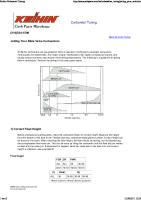
The figure compares the exact response with this approximate response. Note that the comparison is not very good, but what we really want is some approximate curve to estimate what the controller settings ought to be. The following will be the Cohen & Coon controller settings: •
P control:
Cohen & Coon Controller Tuning
-4-
December 21, 2008
Colorado School of Mines CHEN403 Kc = •
1 τ 0.535053 θ 7.47674 1 + = 1 + = 14.3 3τ 0.535053 3 ⋅ 7.47674 K θ
PI control: Kc =
1 K
τI = θ •
0.535053 τ θ 7.47674 0.9 + = 0.9 + = 12.7 θ 12τ 0.535053 12 ⋅ 7.47674
30 + 3( θ / τ )
9 + 20 ( θ / τ )
= 0.535053
30 + 3( 0.535053/7.47674 )
9 + 20 ( 0.535053/7.47674 )
= 1.55
PID control: Kc =
1 K
τI = θ
τ 4 θ 7.47674 4 0.535053 + = + = 18.9 θ 3 4τ 0.535053 3 4 ⋅ 7.47674
32 + 6 ( θ / τ )
13 + 8 ( θ / τ )
τD = θ
= 0.535053
32 + 6 ( 0.535053/7.47674 )
13 + 8 ( 0.535053/7.47674 )
= 1.28
4 4 = 0.535053 = 0.19 11 + 2( θ / τ ) 11 + 2( 0.535053/7.47674 )
Non-Linear Fit to PRC Parameters The use of the inflection point is fairly simple to match parameters for the PRC, but it does not give a very good fit to the system's response. With today's proliferation of computers & data manipulation software, it is almost as easy to fit the parameters using non-linear regression. This can easily be done for the example 2nd order overdamped system using Excel's Solver function. The parameters found are: K = 1.00768 τ = 5.48522 θ = 0.727561
Cohen & Coon Controller Tuning
-5-
December 21, 2008
Colorado School of Mines CHEN403 1.0 0.9 0.8 Exact Inflection Point Rules Non-Linear Fit
0.7 0.6 Y'(t) 0.5 0.4 0.3 0.2 0.1 0.0 0
5
10
15
20
25
30
t
This figure shows that these parameters give a much better fit to the actual response curve. The following will be the Cohen & Coon controller settings:
•
P control:
Kc = •
1 τ θ 1 5.48522 0.727561 ⋅ 1 + = 1 + = 7.81 K θ 3τ 1.00768 0.727561 3 ⋅ 5.48522
PI control:
Kc =
1 τ θ 1 5.48522 0.727561 ⋅ 0.9 + = 0.9 + = 6.82 K θ 12τ 1.00768 0.727561 12 ⋅ 5.48522
τI = θ •
30 + 3( θ / τ )
9 + 20 ( θ / τ )
= 0.727561
30 + 3( 0.727561/5.48522)
9 + 20 ( 0.727561/5.48522)
= 1.90
PID control:
Kc =
1 τ4 θ 1 5.48522 4 0.727561 ⋅ + = + = 10.2 K θ 3 4τ 1.00768 0.727561 3 4 ⋅ 5.48522
τI = θ
32 + 6 ( θ / τ )
13 + 8 ( θ / τ )
Cohen & Coon Controller Tuning
= 0.727561
32 + 6 ( 0.727561/5.48522)
13 + 8 ( 0.727561/5.48522)
-6-
= 1.70
December 21, 2008
Colorado School of Mines CHEN403 τD = θ
4 4 = 0.727561 = 0.26 11 + 2( θ / τ ) 11 + 2( 0.727561/5.48522)
Effect of values on Closed Loop System Response The controller settings from the two PRCs are quite different. The next logical question is how different are the responses when control is turned on. Let's look at a step change to the load for PI control when the transfer function for the disturbance is the same as that for the manipulated variable, i.e., Gd = Gp . The closed loop transfer function will be:
G(s) =
Gp 1 + Gc Gp
=
1 ( s + 1)(5s + 1) 1 1 1 + Kc 1 + τI s ( s + 1)(5s + 1)
=
τI s K c + ( τI + K c τI ) s + 6τI s 2 + 5τI s3
and with a step change to the load, U = 1/ s then: Y ′( s ) =
τI K c + ( τI + K c τI ) s + 6τI s 2 + 5τI s3
The general solution for this can be quite messy (since there are real exponential terms if overdamped and sine/cosine terms if underdamped). Let's only invert this for specific cases of the controller variables. For the controller variables derived by fitting the PRC to the inflection point: Y ′ ( t ) = 0.0800524e −0.686594t +e −0.256703t 0.0226252sin (1.52104t ) − 0.0800524cos (1.52104t ) For the controller variables derived by fitting the PRC using non-linear regression: Y ′ ( t ) = 0.16672e −0.596944t +e −0.301528t 0.0466982sin (1.05468t ) − 0.16672cos (1.05468t )
Cohen & Coon Controller Tuning
-7-
December 21, 2008
Colorado School of Mines CHEN403 0.14 0.12
Inflection Point Fit
0.10
Non-Linear Fit
0.08 0.06 Y'(t) 0.04 0.02 0.00 -0.02 -0.04 0
5
10
15
20
t
This figure shows the response to this disturbance. Which set of controller settings gives the best control depends upon your definition of “best.” The parameters derived from the PRC fit to the inflection point produces a response with a smaller maximum offset, but the parameters derived from the non-linear regression PRC fit produces a response with a better decay ratio.
Cohen & Coon Controller Tuning
-8-
December 21, 2008