![Problems For Solving Chapter 11 [PDF]](https://pdfs.asia/img/200x200/problems-for-solving-chapter-11.jpg)
20 0 2 MB
11.3
467
ANALYSIS OF BEAMS
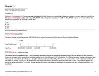
PROBLEMS 11–1. Determine the moments at A, B, and C and then draw the moment diagram. EI is constant. Assume the support at B is a roller and A and C are fixed. 3k
3k
*11–4. Determine the moments at the supports, then draw the moment diagram. Assume B is a roller and A and C are fixed. EI is constant.
4k
15 kN 15 kN 15 kN 25 kN/m
B
A 3 ft
3 ft
A
C 10 ft
3 ft
3m
B 6m
10 ft
2m
2m
2m
Prob. 11–4
Prob. 11–1 11–2. Determine the moments at A, B, and C, then draw the moment diagram for the beam. The moment of inertia of each span is indicated in the figure. Assume the support at B is a roller and A and C are fixed. E = 29(103) ksi.
11–5. Determine the moment at A, B, C and D, then draw the moment diagram for the beam. Assume the supports at A and D are fixed and B and C are rollers. EI is constant.
20 kN/m
30 k
2 k/ft
C
2m
C A
IAB ! 900 in.4
A
8 ft
24 ft
C
B
B I ! 1200 in.4 BC
5m
8 ft
D
3m
5m
Prob. 11–5
Prob. 11–2
11–3. Determine the moments at the supports A and C, then draw the moment diagram. Assume joint B is a roller. EI is constant.
25 kN
11–6. Determine the moments at A, B, C and D, then draw the moment diagram for the beam. Assume the supports at A and D are fixed and B and C are rollers. EI is constant.
9k
15 kN/m
9k
2 k/ft A
B 3m
3m
Prob. 11–3
C 4m
A
C
B 15 ft
15 ft
Prob. 11–6
5 ft
D 5 ft
5 ft
11
468
CHAPTER 11
DISPLACEMENT METHOD
OF
11–7. Determine the moment at B, then draw the moment diagram for the beam. Assume the supports at A and C are pins and B is a roller. EI is constant. 40 kN
11–10. Determine the moments at A and B, then draw the moment diagram for the beam. EI is constant.
20 kN
A
C 4m
2m
A
B 10 ft
Prob. 11–10
Determine the moments at A, B, and C, then draw the moment diagram. EI is constant. Assume the support at B is a roller and A and C are fixed.
*11–8.
6k
11–11. Determine the moments at A, B, and C, then draw the moment diagram for the beam. Assume the support at A is fixed, B and C are rollers, and D is a pin. EI is constant.
6k
0.5 k/ft
B 8 ft
C
30 ft
4m
Prob. 11–7
A
2400 lb
200 lb/ft
B 6m
A N A LY S I S : S L O P E - D E F L E C T I O N E Q U AT I O N S
C
8 ft
6k
B
A
18 ft
4 ft
3 k/ft
4 ft
4 ft
C 12 ft
12 ft
Prob. 11–8
Prob. 11–11
11–9. Determine the moments at each support, then draw the moment diagram. Assume A is fixed. EI is constant.
*11–12. Determine the moments acting at A and B. Assume A is fixed supported, B is a roller, and C is a pin. EI is constant.
20 kN/m 12 k
4 k/ft
11
D
B
A 20 ft
D
C 15 ft
Prob. 11–9
8 ft
8 ft
80 kN
C
B
A
3m
9m
Prob. 11–12
3m
482
CHAPTER 11
DISPLACEMENT METHOD
OF
A N A LY S I S : S L O P E - D E F L E C T I O N E Q U AT I O N S
PROBLEMS 11–13. Determine the moments at A, B, and C, then draw the moment diagram for each member. Assume all joints are fixed connected. EI is constant.
11–15. Determine the moment at B, then draw the moment diagram for each member of the frame. Assume the support at A is fixed and C is pinned. EI is constant.
4 k/ft
2 kN/m B
A
A
B
18 ft 9 ft
3m 4m
C
Prob. 11–13 C
Prob. 11–15
11–14. Determine the moments at the supports, then draw the moment diagram. The members are fixed connected at the supports and at joint B. The moment of inertia of each member is given in the figure. Take E = 29(103) ksi.
*11–16. Determine the moments at B and D, then draw the moment diagram. Assume A and C are pinned and B and D are fixed connected. EI is constant.
20 k
8k
8 ft A
8 ft
15 ft
B A
IAB ! 800 in4
15 k 6 ft
11
C
Prob. 11–14
B
10 ft C
12 ft
6 ft IBC ! 1200 in4
10 ft
D
Prob. 11–16
11.5 11–17. Determine the moment that each member exerts on the joint at B, then draw the moment diagram for each member of the frame. Assume the support at A is fixed and C is a pin. EI is constant.
483
ANALYSIS OF FRAMES: SIDESWAY
11–19. Determine the moment at joints D and C, then draw the moment diagram for each member of the frame. Assume the supports at A and B are pins. EI is constant.
3 k/ ft
2 k/ ft
C
D
B C 15 ft
6 ft
12 ft
10 k
B
A 6 ft
10 ft
5 ft
5 ft
Prob. 11–19
A
Prob. 11–17
11–18. Determine the moment that each member exerts on the joint at B, then draw the moment diagram for each member of the frame. Assume the supports at A, C, and D are pins. EI is constant.
*11–20. Determine the moment that each member exerts on the joints at B and D, then draw the moment diagram for each member of the frame. Assume the supports at A, C, and E are pins. EI is constant. 12 kN/m 10 kN
B
D
C
6m
D
6m 4m
8m 12 kN/ m
E
16 kN/m
15 kN B
A
3m
C
4m
Prob. 11–18 A
Prob. 11–20
11
484
CHAPTER 11
DISPLACEMENT METHOD
OF
11–21. Determine the moment at joints C and D, then draw the moment diagram for each member of the frame. Assume the supports at A and B are pins. EI is constant.
D
A N A LY S I S : S L O P E - D E F L E C T I O N E Q U AT I O N S 11–23. Determine the moments acting at the supports A and D of the battered-column frame. Take E = 29(103) ksi, I = 600 in4.
C
8 kN/m
4 k/ft
6k
6m
B
C
20 ft B
A
A
D 15 ft
5m
20 ft
15 ft
Prob. 11–21
Prob. 11–23
11–22. Determine the moment at joints A, B, C, and D, then draw the moment diagram for each member of the frame. Assume the supports at A and B are fixed. EI is constant.
*11–24. Wind loads are transmitted to the frame at joint E. If A, B, E, D, and F are all pin connected and C is fixed connected, determine the moments at joint C and draw the bending moment diagrams for the girder BCE. EI is constant.
D
E
C B
C
3m 8m
A
B
30 kN/m 3m
11
Prob. 11–22
A
D
F
4m
6m
Prob. 11–24
12 kN