![Profitec 2000 S Battery Charger For Secured DC Power Supplies [PDF]](https://pdfs.asia/img/200x200/profitec-2000-s-battery-charger-for-secured-dc-power-supplies.jpg)
5 0 146 KB
Profitec 2000 S Battery charger for secured DC power supplies
AEG Power Solutions GmbH Department: AE Name: Gf / Wes Alteration state: 03 Date: 08.11.2001
Working instructions 4418 BAL, en
Batterie charger for secured DC power supplies
Contents 1.
General...............................................................................3
2. 2.1 2.2 2.3 2.4 2.5 2.6
Operation modes : ............................................................3 Trickle charge......................................................................3 Boost charge .......................................................................4 Equalizing charge ...............................................................4 Diode check ........................................................................5 Start-up charge ...................................................................5 EPS Operation ....................................................................6
3. 3.1 3.2 3.3
External remote control contact :....................................7 - Release increased charging voltage................................7 - Remote on/off ..................................................................8 - EPS Operation .................................................................9
4. 4.1 4.1.1 4.2 4.2.1 4.2.1.1 4.3
Display and operation.......................................................9 Operator control element ....................................................9 Menu levels .......................................................................10 Display and operation in the operating state "Off" ............11 Service menu ....................................................................13 Adjustment menu ..............................................................14 Display and operation in the operating state "On" ............21
5. 5.1 5.2 5.3 5.3.1 5.3.2
Fault conditions of the equipment ................................24 Self-acknowledging fault conditions with shutdown ..........24 Fault conditions with permanent shutdown .......................26 Fault conditions without shutdown ....................................34 Direct fault report signal ....................................................35 Indirect fault report signal..................................................35
6.
Remote signalling ...........................................................36
Page 2 of 36
4418BAL, en
Batterie charger for secured DC power supplies
1.
General The battery charger -Profitec 2000 S- is intended for the secured power supply to DC loads. A secured DC power supply system is realized together with a stationary battery installation. Battery charger, battery and load are connected in parallel ("standby parallel operation"). The equipment is fitted with thyristors and charges to a regulated characteristic according to DIN 41 772. The regulation is by the control unit with a built-in microcontroller (assembly -A20-). All equipment and process control functions are realized in the software of the micro control unit. A more detailed explanation of the battery charger -Profitec 2000 S- is contained in the respective operating instructions of the equipment.
2.
Modes of operation
i
2.1
NOTE: The display of the -DOB- in the operating level (Selection Menu) shows which of the operating modes listed below can be selected. The nominal values set ex works can be found in the respective technical data sheet -TD-. At manual selection of the operating mode "Boost charge" or "Diode check", an automatic change-over to the operating mode "Trickle charge " takes place after a period of time of 8 hours. Because in the operating mode "Boost charge" the batteries are charged at an elevated voltage and in the operating mode "Diode check" the batteries are charged at a reduced voltage, the automatic changeover prevents an unintended damage to the battery installation.
Operation mode: Trickle charge In the operating mode "Trickle charge" of the -Profitec 2000 Sa continuous charging of the batteries according to an IU characteristic to DIN 41 777 with a Trickle charge voltage of eg 2.23 V//cell for Pb batteries or 1.4 V/cell for NiCd batteries takes place to compensate the self-discharge. This permanently maintains the batteries in a fully charged state as long as no current is drawn from them. The output voltage is maintained constant to ±1 % irrespective of load changes between 0 and 100 % of the rated current and mains voltage fluctuations (see technical data sheet -TD-). The built-in current limiting (IU characteristic), set to the rated current of the battery charger, protects the battery charger from being overloaded.
Page 3 of 36
4418BAL, en
Batterie charger for secured DC power supplies
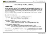
Fig. 1
IU characteristic to DIN 41773
To begin with, the battery is charged at a constant charge current, the difference between the rated equipment current and the load current. The maximum deviation thereby remains within ±2 % of the rated equipment current. For this purpose, a voltage proportional to the Boost charge current is derived across the shunt R91 in the DC circuit and fed to the micro control unit (1st charging stage = I regulation). On reaching the preset charging voltage, the micro control unit holds this voltage constant to within ±1 % at the now decreasing current (2nd charging stage = U regulation). ATTENTION: In the operating modes “Charge” and "Equalizing charge" switch off all voltage sensitive DC loads because the elevated charge voltage is in general not admissible for the loads. Moreover also pay attention to point 3.1!
Do not switch on unless the battery is connected otherwise the elevated no-load voltage may damage the electrolytic capacitors in the DC output. The battery manufacturer's handling instructions and charging specifications must be observed for the equalizing charge. Otherwise the battery may be damaged!
2.2
Operation mode: Boost charge The operating mode "Boost charge" allows to achieve a faster recharge of the batteries in comparison with the operating mode "Trickle charge ". In this operating mode the batteries are charged to an IU characteristic (see Fig. 1) at an elevated charge voltage of, for example, 2.4 V/cell for Pb batteries or 1.55 V/cell for NiCd batteries according to DIN 41773 (see technical data sheet -TD-).
2.3
Operation mode: Equalizing charge The operation mode "equalizing charge" is required after total discharging, insufficient Charging and for regeneration of a sulphated battery. Page 4 of 36
4418BAL, en
Batterie charger for secured DC power supplies
First the battery is charged in the 1st charging stage according to an IU characteristic (see Fig. 2) with a Charging voltage of 2.4 V/cell, a charging current of max. 100% Irated and a charging time of 7 h. When the charging current dies down, the charger switches over to the 2nd chargingstage on reaching one of the 3 set limit values. The battery is then fully charged with an elevated charging voltage of 2.9 V/cell, a chargingcurrent of 5 A per 100 Ah C10 and a charging time of 5 h. The charger automatically switches back to "trickle charging" mode at the end of the 2nd charging stage on reaching one of the 3 set limit values (see technical data sheet -TD-).
2.4
Operation mode: Diode check The operating mode "Diode check" is intended for checking the blocking diodes in the DC distribution board or in the equipment. Thereat the -Profitec 2000 S- battery charger is operated to an IU characteristic according to DIN 41772 (see Fig. 1) with reduced rated voltage of, for example, 2.05 V/cell for Pb batteries or 1.25 V/cell for NiCd batteries.
2.5
Operation mode: Start-up charge The operation mode "Start-up charge" is primarily meant for the startup charge of a new battery (after electrolyte filling). ATTENTION: When filling up the cells and during the subsequent start-up charge, the operating instructions and charge information of the battery manufacturer must be complied with. Otherwise the battery may be damaged! Switch off all voltage-sensitive DC-consumers, since the higher charging voltage is generally not allowed for these consumers. Do not switch on without a connected battery, since the higher noload voltage can destroy the electrolytic capacitors in the DC-output. The operation mode "start-up charge" offers the possibility of charging the battery according to the instructions of the manufacturer with 2 individually adjustable characteristic levels. In addition, the desired values for the charging current or charging voltage and the changeover conditions (limit values) for the charging current, voltage and time can be programmed for each individual characteristic stage via the service menu of the -DOB- . After one of the set limit values has been reached, the program automatically switches from the 1st charging stage to the 2nd charging stage and from the 2nd charging stage to the operation mode "Trickle charge". Because of these freely selectable changeover conditions, any charging characteristic at all can be set. If only one characteristic stage is necessary, the rated and limit values of the 2nd level must be set equal to the rated and limit values of the first level.
Page 5 of 36
4418BAL, en
Batterie charger for secured DC power supplies
equipment voltage
charging stage 2
charging stage 1
limit value U2 rated value U2
limit value U1 U regulation
rated value U1
Trickle charge
I regulation
voltage
equipment current limit value I2
rated value I2
limit value I1
rated value I1
charging time limit value t2
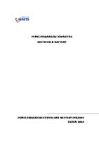
Fig. 2
t2=0 limit value t1
t1=0
Characteristic to DIN 41 772
The factory-set charging data for the start-up charge of the battery can be found in the corresponding technical data sheet -TD-. If the charging data happens to be set to the value "0" or if it is to be changed, the set values of the individual charging stages (desired and limit values) must be manually entered within the allowable limits via the respective service menu (see 4.2.1 above ). Menu 2.8V * SU chrg.1 *
i 2.6
0000A
NOTE: If the display is on "0" after the battery charger is turned on, it is automatically changed over to the operation mode "Trickle charge" after the test phase.
Operation mode: EPS Operation The operating mode " EPS Operation " (mains reserve system mode) is designed to reduce the mains input power of the battery charger-Profitec 2000 S- when it is operated on a mains reserve system (e.g. a diesel-powered emergency generator). Here the -Profitec 2000 S- is driven for power reduction according to an IU characteristic in accordance with DIN 41 772 (see Fig. 1) with a reduced rated voltage of e.g. 2.1 V/cell for Pb batteries or 1.3 V/cell for NiCd batteries or with a reduced rated current of e.g. 50 % (see technical data sheet -TD-).
Page 6 of 36
4418BAL, en
Batterie charger for secured DC power supplies
3
External remote control contact : The control of the user's external potentialfree interlocking contact (see circuit diagram) takes place via the printed circuit card -A14"Mains interface" by an internal potential-isolated DC 24 V control voltage (see circuit diagram). If this blocking of the characteristic is not required, bridge the external interlocking contact at the control terminal strip.
3.1
- Release increased charging voltage With built-in control terminal strip "Release increased charging voltage" (no-voltage contact, closes in case of signalling), the -Profitec 2000 S- battery charger can only be changed over to an operating mode with elevated voltage characteristic (charging, equalizing charging or start-up charging) on condition that the DC loads are switched off. When with switched on equipment an operating mode with elevated voltage characteristic is selected without switching off the DC loads (external interlocking contact still open), then the battery charger will not be changed over to the elevated voltage characteristic. The presently running charging process, eg in the operating mode "Trickle charge ", will not be interrupted. On the display device appears in addition to the operating status message, eg *Trickle charge *, the fault information "Fault!" and the yellow LED signal blinks additionally to the green LED signal. Menu 241V Fault! *Trickle charge*
99.9A
By pressing the "E" key, change-over from operating indication to detail indication (1st menu level) takes place. On the display device of the display and operation board -DOB- appears the actual fault information. Charging or equalizing Charging or start-up Charging blocked by external contact *Fault* Menu
i
NOTE: The fault message is automatically cancelled after 20 seconds.
Page 7 of 36
4418BAL, en
Batterie charger for secured DC power supplies
3.2
- Remote on/off When a control terminal strip of the type "remote -on/off-" is present (operating current contact) , the -Profitec 2000 S- can additionally be switched on and off externally in the operating state "On". When equipment is restarted, the -Profitec 2000 S- must be switched on manually using the membrane key "I" on the left side of the -DOB-. In this case a corresponding status display is output on the display of the -DOB-. The green large-area LED display is also triggered (see pertinent Operating Instructions). Switch off sequence If the -Profitec 2000 S- is switched off using the external remote control contact, the green large-area LED display on the front door of the switched off equipment goes out. The status indication *Off* and the message *Equipment switched off by remote control contact* additionally appear in the display of the display and operating unit DOB-. No control function is then possible on this equipment in the switched off state. Furthermore, the external floating remote signal *Central fault indication* is triggered with a response delay of 10 s. Equipment switched off by remote control contact *Off*
Menu
Switch on sequence If the -Profitec 2000 S- is switched back on using the external remote control contact, then the same sequence control takes place as is described for manually switching on the equipment.
i
NOTE: If a fault occurs in the equipment, it is not possible to acknowledge the fault with the external remote control contact. Before the -Profitec 2000 Sis restarted, the stored fault indication must be acknowledged manually with the membrane key "O/I" of the -DOB- after the fault has been eliminated. Option: ⇒ The remote control contact can only be used to switch on the equipment. ⇒ Remote control contact with additional equipment fault acknowled gement via the Off command. In this case the -Profitec 2000 S- can also be switched on via the external remote control contact when the equipment is restarted
Page 8 of 36
4418BAL, en
Batterie charger for secured DC power supplies
3.3
- EPS Operation If the control terminal "EPS Operation" exists, the battery charger Profitec 2000 S- is switched automatically to the EPS mode with reduced voltage or current characteristic when the external trigger contact of the mains reserve system is open. In the display on the DOB-, the operating mode display switches from e.g. *trickle charge* to * EPS Operation * and the green LED operating indicator changes from steady to flashing.
4.
Display and operation
4.1
Operator control element The display and operation board -DOB- is mounted into the front door of the equipment cubicle. The -DOB- effects the required operation procedures, eg selection of an operating mode, and indicates the pertinent display messages and LED indication signals for the different operating conditions of the battery charger -Profitec 2000 S-.
i
NOTE: The maximum value of the voltage indication in the LCD INDICATION of the -DOB- is 150% of the rated voltage of the battery charger Status messages are enclosed by asterisks "*", notes and instructions are enclosed by exclamation marks "!". When the three-phase mains voltage is applied, eg when putting into service, the rectifier control electronics are activated and a diagnosis program starts. Then the three differently coloured large-area LED indications light up first one after the other and are then blinking together. Self test ! Please wait ! *Diagnosis*
V:SD2AB457.D00 Self test ! Please wait !
V:SD2MS457.D00
Page 9 of 36
V:SD2AB457.D00
4418BAL, en
Batterie charger for secured DC power supplies
After this the battery charger automatically goes into the operating state "Off". The battery charger -Profitec 2000 S- is switched on by pressing the membrane key "I" on the left-hand side of the -DOB-, upon which an associated operation or fault signal indication (basic level) appears on the display device of the -DOB-. In addition, a green LED indication lights up at operation or a red or yellow LED indication lights up at a fault. The indication of the current or the voltage in large-scale characters allows the operator a permanent supervision of the operation mode. After pressing the membrane key "0", the battery charger is switched off via the mains contactor. The membrane keys "I" and "0" thus perform the function of an On/Off control switch.
4.1.1
Menu levels The display of the actual operation data on the display and operation board takes place in 4 menu levels: Basic level: Operation or fault indication In the basic level the cursor is always in the selection field "Menu". In the basic level no other selection field is available. 1st menu level: Detail indication 2nd menu level: Operating level 3rd menu level: Operating hours counter and fault history The transfer into the 1st menu level takes place when pressing the "E" key. After transfer into the 1st menu level, the cursor is in the selection field "Menu" again. When the "E" key is pressed again, transfer into the 2nd or 3nd menu level takes place.
i
Note: If after transfer into the menu levels no operation via the cursor ± or the enter keys takes place within 18 s, the indication reverts to the original position (basic level). The design of the display screen masks to the preselected schematics allows the operator a fast and sure detection of the relevant system data. The design of the operation status masks and of the fault indication masks is shaped so that an output wording with the same kind of data content is always indicated at the same positions. The use of enclosing special characters draws the attention of the operator to important data: A large-area LED indication in three different colours also allows the operator to distinguish always the operating status of the battery charger -Profitec 2000 S- from a greater distance. Adjustment of contrast
Page 10 of 36
4418BAL, en
Batterie charger for secured DC power supplies
For changed line of sight to the display and operation board -DOB- on the front door of the equipment cubicle, the keys → and ← allow one to readjust the contrast of the LCD INDICATION in the basic level (large-scale indication).
4.2
Display and operation in the operating state "Off"
i
Note: When the battery charger is switched off, the operating modes "trickle charge" or "EPS mode" are selected manually (permanent = static) and the Service Menu is called up (see paragraph 4.2.1). In the operating state "Off" no LED indication lights up on the display and operation board -DOB-. However, the external potential-free remote alarm signal *Central fault* is actuated (see paragraph 6). Basic level In the operating state "Off" the equipment data (rating plate) is indicated on the display device. Example: Equipment type: D 400 G 26/100 BWrug-Vp Equipment no.: 81500174.E00 Menu
*Off*
1st menu level If the equipment is in the "Off" state, transfer to the detail indication (1st menu level) takes place when the "E" key is pressed. In the standard design of the battery charger -Profitec 2000 S- the following wording appears on the display device of the -DOB-: Battery voltage : 24.1V Output current : 0000A
desired: max:
29.2V 100A Menu
If the battery charger -Profitec 2000S- has a blocking diode -V17- in the DC output, the display also shows the DC voltage upstream of the blocking diode. Battery voltage : 24.1V Output current : 0000A Charger voltage : 0000V
i
desired: max:
29.0V 100A Menu
NOTE: The DC voltage values displayed refer to the parameters given in the Technical Data Sheet -TD- + 0.8 %. (inclination of characteristic curve)
Page 11 of 36
4418BAL, en
Batterie charger for secured DC power supplies
2nd menu level When the "E" key is pressed twice on the display and control unit -DOB-, the display changes from the operating display through the detail display into the operating level. The possible operating modes of the battery charger -Profitec 2000 S- which can be selected when the device is switched off appear on the display device. Menu
>Trickle charge EPS mode
From 1st menu level
The currently set operating mode is marked by the symbol ">", whilst the cursor is initially on "Menu". With the aid of the arrow keys → or ←, the flashing cursor is positioned in front of the "EPS mode" in the selection menu. When the enter key "E" is pressed, the newly selected operating mode is then entered with the symbol ">". The following indication appears on the display device of the -DOBduring the storing time of the new operating mode into the nonvolatile data memory (read-only memory): Basic settings are being stored ! Please wait ! After this the operating display automatically reverts back to the basic level, i.e. in the "Off" state, the unit data (rating plate) is displayed. The battery charger -Profitec 2000 S- is then switched on via the membrane key on the left side of the -DOB-. The respective operating display thereby appears on the LED indication of the -DOB-, i.e. the charging current or the charging voltage is displayed in large-scale characters. The selected operation mode *EPS mode* is displayed in the status line. In addition, the green blinking large-area LED indication is controlled with increased charging voltage during the charging process.
3rd menu level By pressing the Enter key "E" on the display and operation board -DOB- three times, the display changes from the operating display to the fault and operating hours display. The following text appears on the display: Menu from 2nd menu level
>Faults Operation: 0h
Fault display
Page 12 of 36
4418BAL, en
Batterie charger for secured DC power supplies
The last 4 faults which were transmitted by the remote signalling are saved in a fault history. With the right arrow key → the cursor is positioned in front of the "Faults" message and the Enter key is pressed for acknowledgement. 4
DC- or control circuit fuse blown
*Fault*
The last fault message with identification no. 4 appears top left on the display. With the arrow keys ← or → the last 4 fault messages can be called up (the fault message with identification no. 2 is the penultimate message). Operating Display The total of all operating hours of the battery charger -Profitec 2000 S- is displayed. By pressing the Enter key "E", you return to the operating display. 4.2.1
Service Menu The service menu offers the user the possibility to individually fit specific requirements of the secured power supply by changing the desired values in the preset adjustment ranges (i.e. charging voltage). The service menu can only be called up when the battery charger is switched off. For this, the arrow keys ↓ and ↑ are pressed one after the other on the display and operation board -DOB-, and the LCD indication changes over from the rating plate (equipment data) to the service menu.
i
NOTE: The 4 digit code no. for the battery charger -Profitec 2000 S- can be found in the corresponding technical data sheet -TD-. ServiceI Adjustment I I I
Please enter code no Code-no. :
0 more break
The arrow keys → and ← are used to position the cursor before the CODE no. 0_ to be entered. After this the arrow keys ↓ or ↑ are pressed in order to enter the code no. If one of the two membrane keys is held down at the same time, the value automatically decreases or increases in different speed stages. If the correct code no. has been set, one comes into the adjustment menus after pressing the "E" key (see 3.2.1.1 above).
Page 13 of 36
4418BAL, en
Batterie charger for secured DC power supplies
If the cursor is in the position "further", one comes into the menu "wrong CODE no." after pressing the "E" key. The input must then be repeated. ServiceI Adjustment I I I
Wrong code-no. Repeat entry break
If the cursor is in the position "quit" one goes back to the rating plate display after pressing the "E" keys.
4.2.1.1 Adjustment Menus ATTENTION: When entering the new DC voltage setpoint, take into account inclination of characteristic curve +0.8%! (New setpoint + 0.8 %)! Changing or entering the individual desired values (limit values) is done via the arrow keys ↓ or ↑ as described above. The desired values or limit values changed in the individual adjustment menus are taken over by simply pressing the Enter key "E". The display then switches to the next adjustment menu. After the last value to be set is entered, all newly entered charging data is saved by pressing the enter key "E". In this case the cursor must be positioned next to the last value.
For Time delay after mains return Desired value:
Adjustment range
Time:....................................... 0 - 250 sec. ServiceI Adjustment I I I
Time delay after mains return 0 sec more break
After entering the setpoint with the aid of the arrow keys ↓ and ↑ to the new value "5 sec", the next setting menu is reached by pressing the Enter key "E". ATTENTION: The values preset in the factory for the individual equipment monitors (see It. 4) are not adjusted as well!.
For operation mode: Trickle charge Desired value: ....................... Adjustment range Voltage: .................................. 2.0 - 2.48 V/cell with Pb - batteries 1.2 - 1.45 V/cell with NiCd-batteries Page 14 of 36
4418BAL, en
Batterie charger for secured DC power supplies
Example: Old setpoint: 2,23 V/cell x 13 Pb-cells = 29,0 V + 0,8% = 29,2 V New setpoint: 2,27 V/cell x 13 Pb-cells = 29,5 V + 0,8% = 29,8 V ServiceI Adjustment I I I
Desired value Trickle charg.
29.8V more break
After entering the setpoint with the aid of the arrow keys ↓ and ↑ to the new value "29.5 V", the next setting menu is reached by pressing the Enter key "E". Desired value: ....................... Adjustment range Current:................................... 0 - 100% of Irated ServiceI Adjustment I I I
Desired value Trickle char.cur.
90 A more break
For operation mode: Boost charge Adjustment value: ................ Adjustment range Voltage: .................................. 2.1 - 2.6 V/cell with Pb - batteries 1.3 - 1.60 V/cell with NiCd-batteries Current:................................... 0 - 100% of Irated Input mode as described before.
For operation mode: Diode check Adjustment value: ................ Adjustment range Voltage: .................................. 1.7 - 2.35 V/cell with Pb - batteries 0.0 - 1.40 V/cell with NiCd-batteries Current:................................... 0 - 100% of Irated Input mode as described before. For operation mode: EPS mode Adjustment value: ................ Adjustment range Voltage: .................................. 1.7 - 2.35 V/cell with Pb - batteries 0.0 - 1.40 V/cell with NiCd-batteries Current:................................... 0 - 100% of Irated Input mode as described before. Page 15 of 36
4418BAL, en
Batterie charger for secured DC power supplies
For operation mode: Equalizing charge Adjustment value: ................ Adjustment range Voltage: .................................. 50 - 150% of Urated Current:................................... 0 - 100% of Irated Time:....................................... 0 - 182 h Input example: Profitec 2000 S: ...................... D400G26/100 Bwrug-Vp Battery type ............................ 13 Pb cells Battery capacity ...................... 400 Ah Characteristic:......................... IUIUoU characteristic
with the following Boost charge data (setting points): Boost charge stage 1: .......... IU characteristic UEqualiz.charge1 ................... = 2.4 V/cell ICurrent equ.chrg.1 ................. = Irated
= 31.2 V = 100 A
tmax time equ.chrg1 ............... = 7 h Boost charge stage 2: .......... IU-characteristic UEqualiz.charge2 ................... = 2.9 V/cell ICurrent equ.chrg.2 ................. = 5 A/100Ah
= 37.7 V = 20 A
tmax time equ.chrg2 ............... = 5 h First the battery is charged in the 1st charging stage according to an IU characteristic with a charging voltage of 2.4 V/cell, a charging current of max. 100% Irated and a charging time of 7 h. When the charging current dies down, the charger switches over to the 2nd charging stage on reaching one of the 3 set limit values. The battery is then fully charged with an elevated charging voltage of 2.9 V/cell, a charging current of 5 A per 100 Ah C10 and a charging time of 5 h. The charger automatically switches back to "trickle charging" mode at the end of the 2nd charging stage on reaching one of the 3 set limit values. With this equalizing charge according to the above example with both characteristic stages, the setting of the setpoints and the resultant limit values must be done as follows: Charging stage 1:
Setting point
Voltage : ..... The charging voltage is determined in the example as follows : UEqualiz.charge1 = 2,4 V/cell = 31.2 V + 0,8% = 31,5 V
Page 16 of 36
4418BAL, en
Batterie charger for secured DC power supplies
ServiceI Adjustment I I I
Desired value Equaliz.charge1
31.5V more break
After entering the setpoint with the aid of the arrow keys ↓ and ↑ to the value "31.5 V", the next setting menu is reached by pressing the Enter key "E". Current:................................... The max. charging current is determined as follows : ICurrent equ.chrg.1 = Irated = 100 A ServiceI Adjustment I I I
Desired value Current equ.chrg.1
100A more break
Time:....................................... Since the start charging times of the two characteristic stages always begin with 0 (see figure 2), no setpoint settings are required for these in the service menu. Limit value (switching conditions)
Time:....................................... The charging time in the 1st charging stage is assumed to be 7 h : tmax time equ.chrg1 = 7 h ServiceI Limit value Adjustment I max time equ.chrg1 I I
7:00h more break
Voltage : ...............................The voltage limit value must be > the setpoint and is determined as follows: UEqualiz.charge1 = 2,45 V/cell = 31.9 V + 0,8 % = 32.2 V ServiceI Limit value Adjustment I Equaliz.charge1 I I
32.2V more break
Current:.................................The current limit value must be < than the setpoint and is set = to the charging current of the 2nd charging stage: ICurrent equ.chrg.1 = 5 A/100Ah = 20 A
Page 17 of 36
4418BAL, en
Batterie charger for secured DC power supplies
ServiceI Limit value Adjustment I Current equ.chrg.1 I I Charging stage 2:
20A more break
Setting point
Voltage : ... An elevated voltage is used for charging in the 2nd charging stage to guarantee full battery charging: UEqualiz.charge2 = 2,9 V/cell = 37.7 V +0,8% = 38,0 V ServiceI Adjustment I I I
Desired value Equaliz.charge2
38.0V more break
Current:.................................Now a reduced current is used for charging: ICurrent equ.chrg.1 = 5 A/100Ah = 20 A ServiceI Adjustment I I I
Desired value Current equ.chrg.2
20A more break
Limit value (switching conditions) Time:.....................................The charging time in the 2nd charging stage is assumed to be 5 h : tmax time equ.chrg2 = 5 h ServiceI Limit value Adjustment I max time equ.chrg2 I I Voltage :
5:00h more break
The voltage limit value must be > than the setpoint and is determined as follows: UEqualiz.charge2 = 2,95 V/cell = 38.35 V ServiceI Limit value Adjustment I Equaliz.charge2 I I
38.35V more break
Current:................................... The current limit value must be < than the setpoint and is set to 0 A : ICurrent equ.chrg.2 = 0 A
Page 18 of 36
4418BAL, en
Batterie charger for secured DC power supplies
ServiceI Limit value Adjustment I Current equ.chrg.2 I I
0A more break
After the last value to be set is entered, all newly entered charging data is saved by pressing the enter key "E". In this case the cursor must be positioned next to the last value. The following text appears on the display during the data saving process. Basic settings are being stored ! Please wait ! The battery charger -Profitec 2000 S- is then switched on via the membrane key " I " on the left side of the -DOB-. A corresponding status display is shown on the LED indication of the -DOB-, i.e. the charging current or the charging voltage is displayed in large-scale characters. The display of the selected operation mode *Equaliz.charge* appears in the status line. In addition, the green blinking large-area LED indication is triggered.
Operating indication
Menu 31,2V *Equaliz.charge*
99.9A
After the equaliz. charge has ended, an automatic transfer back to the operation mode "Trickle charge" takes place. The display of the operation mode "Trickle charge" appears in the status line. In addition, the shining green large-area LED indication changes over from blinking light to steady light. Menu 29V *Trickle Charge*
40A
For operation mode: Start-up charge Adjustment value: ................ Adjustment range Voltage: .................................. 0 - 150% of Urated Current:................................... 0 - 100% of Irated time:........................................ 0 - 182 h
Page 19 of 36
4418BAL, en
Batterie charger for secured DC power supplies
The technical data of the battery manufacturer must be complied with. Input mode as described under operating mode "Equalizing charge".
Input example: Profitec 2000 S: ...................... D400G26/100 Bwrug-Vp Battery type ............................ 13 Pb cells Characteristic.......................... I- Characteristic Charging current:.................... I = 40 A Charging length: ..................... t= 15 h Only one characteristic stage is necessary for this start-up charge. The desired and limit values for current and voltage of the 2nd stage are therefore set equal to the 1st stage and the limit value of the 2nd stage is set equal to 0. Since the start charging times of the two characteristic stages always begin with 0 (see figure 2), no setpoint settings are required for these in the service menu. Voltage:
Setting point No voltage regulation takes place with the I-characteristic. I.e. the rated voltage value is set to the max. possible value. desiredU1= desiredU2= 150%Ur= 39 V Limit val. No voltage-independent changeover should take place. I.e. the limit voltage value must = the desired value and is also set equal to the max. possible value. limitU1= limitU2= 150%r= 39 V This shuts down the voltage regulation.
Current
Setting point The desired current value is found in the treatment specifications of the battery manufacturer and is taken here to be 40 A. ratedI1= ratedI2= 40 A Limit val. No current-dependent changeover should take place. I.e. the limit current value is set to 0. limitI1= limitI2= 0 A
Page 20 of 36
4418BAL, en
Batterie charger for secured DC power supplies
Time
4.3
Limit val. The max. charging time is also found in the treatment specifications of the battery manufacturer and is taken here, for example, to be 15 h. Since only one stage is necessary, the time of the 2nd stage is set to 0. After the 1st stage has ended, it reverts back to Trickle charge. limitt1= 15 h limitt2= 0 h
Display and operation in the operating state "On"
i
NOTE: With a switched on -Profitec 2000 S- battery charger, only a transient (temporary) manual change of an additional operating mode according to the selection menu is possible. However, this change applies only to the actual charging operation. After mains failure or equipment shutdown and battery charger restart, the operation mode which has been preselected and programmed at last in the "Off" system status becomes valid again. The battery charger -Profitec 2000 S- is switched on by pressing the membrane key "I" on the left-hand side of the -DOB-, upon which an associated operation indication (basic level) appears on the display device of the -DOB-. In addition, a green LED indication lights up at operation or a red or yellow LED indication lights up at a fault.
Basic level An operation indication (basic level) assigned to the operating state of the equipment is permanently indicated on the display device of the DOB- on the front door of the equipment cubicle. Charge current or charge voltage are indicated there by large-scale characters. In addition, the associated green large-area LED indication below the display device in the -DOB- is illuminated.
Examples:
at U characteristic
Menu 29.0V *Trickle charge*
Page 21 of 36
99.9A 4418BAL, en
Batterie charger for secured DC power supplies
at I characteristic
Menu 100A *Trickle charge*
29.9V
1st menu level If the equipment is switched on, transfer to the detail indication (1st menu level) takes place on pressing the "E" key. In the standard design of the battery charger -Profitec 2000 S- the following wording appears on the display device of the -DOB-: Battery voltage : 29.0V Output current : 100A
desired: max:
29.0V 100A Menu
If the battery charger -Profitec 2000S- has a blocking diode -V17- in the DC output, the display also shows the DC voltage upstream of the blocking diode.
Battery voltage : 29.0V Output current : 100A Charger voltage : 29.7V
desired: max:
29.0V 100A Menu
2nd menu level When the "E" key is pressed, the display indication changes from the 1st menu level to the 2nd menu level (operating level). The display device indicates the possible modes of operation of the battery charger -Profitec 2000 S- which can be selected when the equipment is switched on. The currently set operating mode, eg "Trickle charge", is marked with the symbol ">" while the cursor is first in the position "Menu". If another operation mode according to the selection menu is desired, make the selection as described in the operating instructions for the additionally selectable operating modes. The currently set operating mode, eg "Trickle charge", is marked with the symbol ">" while the cursor is first in the position "Menu". Examples: Menu From 1st menu level
Su chrg
>Trickle charge Charging Equaliz.charge Diode check
If another operation mode, eg "Boost charge", according to the selection menu is desired, make the selection as described in the operating instructions for the additionally selectable operating modes.
Page 22 of 36
4418BAL, en
Batterie charger for secured DC power supplies
Menu 31.2V 00:00h *Boost charge*
99.9A
In the operating mode "Boost charge" the display also shows the Boost charge time.
3rd menu level When pressing the Enter key "E" on the display and operation board -DOB- three times, the display indication changes from the operating display to the operating hours and fault display. The same display as described in paragraph 4.2 appears.
Menu from 2nd menu level
Page 23 of 36
>Faults Operation: 0h
4418BAL, en
Batterie charger for secured DC power supplies
5.
Fault conditions of the equipment The following fault conditions of the equipment are distinguished: ⇒ Self-acknowledging fault conditions (standby) with shutdown and automatic restart after elimination of the fault condition. ⇒ Fault conditions with permanent shutdown. ⇒ -Fault conditions without shutdown, report only.
5.1
Self-acknowledging fault conditions with shutdown In the event of a mains disturbance according to paragraph 5.1, the battery charger -Profitec 2000 S- will be shut down. On the display and operation board -DOB- on the front door of the equipment cubicle, the red LED indication blinks, the status message, eg *Float charge*, and the associated fault report signal together with a note concerning the fault appear on the display device. The response delay of the fault report signal to the external central fault signalling (see paragraph 6.) amounts to 2 minutes. After elimination of the fault condition, eg after the return of the mains supply, the battery charger switches on again automatically. Three-phase AC undervoltage monitoring Set values:.............................. See technical data sheet -TDProtective function: ................. Overload protection for transformer and rectifier stack, increased stress of smoothing capacitors or battery by harmonics on break of one phase Status message:..................... *Trickle charge* Report signal: ......................... Mains disturbance Note concerning fault:............. Mains disturbance, mains failure or mains undervoltage! since 00:00 h LED indication: ....................... red blinking Mains disturbance Mains failure or mains undervoltage ! since 00:00 h *Trickle charge* Menu Note: ....................................... If despite a fault alarm the three-phase AC mains feed is present across the input terminals, check the supply lines up to the plugboard terminal -X3- and the supply lines at the plugboard terminal -X5- on the printed circuit card -mains interface A14-. Page 24 of 36
4418BAL, en
Batterie charger for secured DC power supplies
Three-phase AC overvoltage monitoring Set value:................................ See technical data sheet -TDProtective function: ................. Overvoltage protection for transformer and rectifier stack Status message:..................... *Trickle charge* Report signal: ......................... Mains disturbance Note concerning fault:............. Mains overvoltage ! since 00:00 h LED indication: ....................... red blinking Mains disturbance Mains overvoltage ! since 00:00 h *Trickle charge*
Menu
Mains frequency monitoring Set value:................................ Response value: frated ±10 % delay 40 ms Return value: frated ±8 % delay 2 s Protective function: ................. Protection of equipment, load and battery against increased stress by harmonics Status message:..................... *Trickle charge* Report signal: ......................... Mains disturbance Note concerning fault:............. Frequency deviation or phase broken! LED indication: ....................... red blinking Mains disturbance Frequency deviation or phase broken since 00:00 h *Trickle charge* Menu
Page 25 of 36
4418BAL, en
Batterie charger for secured DC power supplies
Monitoring of rotating electric field (Sequence of lines so that electric field rotates in clockwise direction) Protective function: ................. Supervision of mounting errors Status message:..................... *Trickle charge* Report signal: ......................... Mains disturbance Note concerning fault:............. Phase seqence incorrect phase broken! LED indication: ....................... red blinking Mains disturbance Phase sequence incorrect phase broken ! since 00:00 h *Trickle charge* Menu 5.2
Fault conditions with permanent shutdown In the event of an equipment fault according to paragraph 5.2 the battery charger -Profitec 2000 S- will be shut down. On the display and operation board -DOB- on the front door of the equipment cubicle, the red LED indication blinks, the status message "Fault" and the associated fault report signal together with a note concerning the fault appear on the display device. Moreover the external potentialfree remote alarm signal *Central fault alarm* is actuated with a response delay of 10 seconds. For checking the fault condition of the battery charger, a restart can be initiated first. To do this, reset the indicated fault report signal by pressing the membrane key "0" of the -DOB- (equipment off). Restarting takes then place when the membrane key "I" is pressed. Check whether all green LED indications on the front plate of the MCS control unit -A20- and on the thyristor trigger pulse control modules light up. If the fault report signal is indicated again on the display device of the -DOB-, an equipment fault exists in the -Profitec 2000 S-. If the fault cannot be cleared with the help of the fault alarms described in the following, call the AEG Service (Hotline 049-2902-763-100). Synchronization monitoring Set values:.............................. Response value: 30 % of t/2 Return value: 2 half-waves without disturbance Pulse blocking undelayed Equipment shutdown 1 s delayed Protective function: ................. Internal synchronization faults, eg at transient response process, at spurious pulses/mains transients false triggering is prevented, thereby protection of power controller or fuses
Status message:..................... *Fault* Page 26 of 36
4418BAL, en
Batterie charger for secured DC power supplies
Report signal: ......................... Synchronization fault Note concerning fault:............. Fault in mains zero crossing detection! LED indication: ....................... red blinking Synchronization fault Fault in mains zero crossing detection! Menu
*Fault*
Note: ....................................... Check the supply lines at the plugboard terminals -X3- and -X5- on the printed circuit card -mains interface -A14-. Stack monitoring Fault detection: ....................... Current > 5 % and fault f300Hz > 1,5 s Release: ................................. > 5 % of rated equipment current delay 1.5 s Protective function: ................. Protection of thyristor-/diodes, break of phase/phase unbalance, fault in control circuit, pulse pattern fault Status message:..................... *Fault* Report signal: ......................... Power circuit disturbance Note concerning fault:............. Fault in thyristor stack or in the control! LED indication: ....................... red blinking Power circuit disturbance Fault in thyristor stack or in the control *Fault*
Menu
Note: ....................................... Check the power semiconductor devices as described in paragraphs 9.2 and 9.3 of the applicable operating instructions. It might be possible that a break of phase exists in the threephase AC mains feed.
DC current monitoring Set values:.............................. I 2 % of desired current Desired current = rated equipment current referred to the desired value Delay 20 s Protective function: ................. Protection of equipment Status message:..................... *Fault* Report signal: ......................... Abnormality in current limiting
Page 27 of 36
4418BAL, en
Batterie charger for secured DC power supplies
Note concerning fault:............. Regulation fault! LED indication: ....................... red blinking Abnormality in current limiting Regulation fault! Menu
*Fault*
Note: ....................................... It is likely that the micro control unit A20- has developed a fault. DC voltage monitoring
i
NOTE: DC voltage monitoring is not effective if Profitec 2000S fitted with the blocking diode V17.
Set values:.............................. U 2 % of desired voltage eg desired voltage = 2.23 V/cell Delay 30 s Protective function: ................. Protection of load, battery Status message:..................... *Fault* Report signal: ......................... Direct voltage abnormality Note concerning fault:............. Regulation fault! LED indication: ....................... red blinking Direct voltage abnormality Regulation fault! *Fault*
Menu
Note: ....................................... It is likely that the micro control unit A20- has developed a fault.
DC overvoltage
i
NOTE: The DC overvoltage monitoring is only active in the operating modes "trickle charge" and "automatic charge (option)" which means that the DC overvoltage monitoring is blocked in operating modes with increased chargingvoltage. If an equipment shutdown takes place due to the three DC monitoring criteria mentioned below, a corresponding output wording appears on the display device of the -DOB-. At voltage reduction by pulse reset, an equipment shutdown takes place only after the pulse phase back has been called into action three times within 60 s.
Page 28 of 36
4418BAL, en
Batterie charger for secured DC power supplies
- Voltage reduction by pulse reset - Undelayed Set values:.............................. See technical data sheet -TDProtective function: ................. Protection of load, battery Status message:..................... *Fault* Report signal: ......................... DC overvoltage without delay Note concerning fault:............. Regulation fault! LED indication: ....................... red blinking DC overvoltage without delay Regulation fault! Menu
*Fault* - Delayed
Set values:.............................. See technical data sheet -TDProtective function: ................. Protection of load, battery Status message:..................... *Fault* Report signal: ......................... DC overvoltage with delay Note concerning fault:............. Regulation fault! LED indication: ....................... red blinking DC overvoltage with delay Regulation fault! *Fault*
Menu
- Safety shutdown: Set value:................................ See technical data sheet -TDProtective function: ................. Protection of load, battery Status message:..................... *Fault* Report signal: ......................... DC overvoltage safety shutdown Note concerning fault:............. Regulation fault! LED indication: ....................... red blinking
Page 29 of 36
4418BAL, en
Batterie charger for secured DC power supplies
DC overvoltage safety shutdown Regulation fault! Menu
*Fault*
Note: ....................................... When the fault report signal "DC overvoltage" is indicated, switch off the battery charger by pressing the membrane key "O" of the DOB. Then disconnect the equipment from the DC loads by opening the load-break fuse isolator in the DC output. Restarting then takes place when the membrane key "I" is pressed. If the fault report signal "DC overvoltage" is indicated again on the display with the equipment operated at no-load, it is likely that a fault exists in the micro control unit -A20-.
DC undervoltage Set value:................................ UDC < 2.1 V/cell for Pb batteries UDC < 1.31 V/cell for NiCd batteries UDC < 95% Urated for mains-rectifier design Delay 20 s Monitoring function: ................ U characteristic Status message:..................... *Fault* Report signal: ......................... DC undervoltage Note concerning fault:............. Regulation fault! LED indication: ....................... red blinking DC undervoltage Regulation fault! *Fault*
Menu
Note: ....................................... Check the DC voltage in the equipment in front of the blocking diode -V17-. To do this, first of all reset the fault report signal by pressing the membrane key "0" and then restart the battery charger by pressing the membrane key "I". If the DC voltage is present in front of the blocking diode -V17-, the blocking diode -V17- is faulty.
Page 30 of 36
4418BAL, en
Batterie charger for secured DC power supplies
Ripple monitoring Set value:................................ Peak-to-peak load voltage > 7.5 %tri.chrg ±10 % time-delay 5 seconds Protective function: ................. Protection of load, Status message:..................... *Fault* Fault information:.................... DC voltage ripple too high LED indication: ....................... red blinking DC voltage ripple too high Menu
*Fault*
Note: ....................................... Check the smoothing capacitor component -C11-. Short circuit monitoring Set value:................................ See technical data sheet -TDtime-delay 1 second Protective function: ................. Protection of load, eg against damage by fire Status message:..................... *Fault* Report signal : ........................ Short circuit in DC output feeder! Note concerning fault:............. System fault! LED indication: ....................... red blinking Short circuit in DC output feeder System fault! *Fault*
Menu
Monitoring the actual voltage value line for interruption
i
NOTE: Monitoring the actual voltage value line for interruption is not effective if Profitec 2000 S is fitted with the blocking diode V17
Page 31 of 36
4418BAL, en
Batterie charger for secured DC power supplies
Set value:................................ UDC < 5 % of Urated Delay 1.2 s Protective function: ................. Monitoring of voltage measuring circuit Status message:..................... *Fault* Report signal: ......................... Break of actual voltage value line LED indication: ....................... red blinking Break of actual voltage value line Break of line or fuse blown! Menu
*Fault*
Note: ....................................... Check the intermediate line of the printed circuit card MCS -A20- up to the plug block X121:D6; D8. Monitoring the actual current value line for interruption Set value:................................ IDC > 120 % Irated and inverter end position Delay 1 s Protective function: ................. Monitoring of current measuring circuit Status message:..................... *Fault* Report signal: ......................... Break of actual current value line LED indication: ....................... red blinking Break of actual current value line
*Fault*
Menu
Note: ....................................... Check the shunt measuring leads of the printed circuit card MCS -A20- up to the plug block X121:Z16; Z20.
Break of MCS supply line Set value:................................ Usupply < 5 % Urated Delay 1.2 s Protective function: ................. Monitoring of DC supply line Status message:..................... *Fault* Report signal: ......................... Failure of MCS DC supply Note concerning fault:............. Break of line or fuse blown! LED indication: ....................... red blinking
Page 32 of 36
4418BAL, en
Batterie charger for secured DC power supplies
Failure of MCS DC supply Break of line or fuse blown! Menu
*Fault*
Note: ....................................... Check the supply line and the associated fuse protection at printed circuit card MCS -A20- up to plug block X121:D6, D14, Z4.
Analog circuit monitoring Adjustment value: ................... Reference voltages or the DC actual value differ more than 0.7 % from the rated value, for more than 40 s Protective function: ................. Monitoring the DC supply line Status message:..................... *Fault* Report signal: ......................... Measured values incorrect LED indication: ....................... red blinking Measured values incorrect Menu
*Fault*
Note: ....................................... Monitoring the reference voltage of the analog circuit and the earthing cable of the supply voltage Q10 motor protection switch and for design -Profitec 2000 S-: DC fuse with striker pin Tripping via auxiliary contact or striker pin of fuse Protective function: ................. Protection of equipment, load, battery Status message:..................... *Fault* Report signal: ......................... DC or control circuit fuse blown LED indication: ....................... red blinking DC- or control circuit fuse blown
*Fault*
Menu
Self test Status message:..................... *Fault* Report signal: ......................... Self test fault Note concerning fault:............. Equipment or process parameter incorrect! Page 33 of 36
4418BAL, en
Batterie charger for secured DC power supplies
LED indication: ....................... red blinking Remark: .................................. Fault occurs when not all data has been correctly stored after the transfer of a new software version or after a data loss in the non-volatile memory EEPROM- (faulty component part) of the MCS. Self test fault Equipment or process param. incorrect! Menu
*Fault*
Note: ....................................... Fault occurs when not all data has been correctly stored after the transfer of a new software version or after a data loss in the non-volatile memory EEPROM- (faulty component part) of the MCS.
Watchdog monitoring Set value:................................ Program runtime until watchdog reset > 65 ms Protective function: ................. Monitoring of MCS program run Status message:..................... *Fault* Report signal: ......................... Program disturbance since 00:00 h LED indication: ....................... red blinking Program disturbance since 00:00 h *Fault*
Menu
Note: ....................................... It is likely that the micro control unit A20- has developed a fault.
5.3
Fault conditions without shutdown, report signal only The -Profitec 2000 S- battery charger will not be shut down under fault conditions. The presently running charging process will not be interrupted. However, the external potential-free remote signal *Central fault alarm* will be actuated with a response delay of 10 seconds. The following fault alarms are distinguished:
Page 34 of 36
4418BAL, en
Batterie charger for secured DC power supplies
5.3.1
Direct fault report signal On the display device of the display and operation board -DOB- the status message *Fault* and the associated fault report signal with fault source indication appears. The LED indication remains unchanged. Communication fault When the connection between the display and operation board -DOBand the micro control unit -MCS- is interrupted, a control of the system via the -DOB- is no longer possible. The battery charger does, however, continue to operate unaffected by this fault condition. Set value:................................ Five attempts (approx. 100 ms) of the DOB- to communicate with the micro control unit Status message:..................... *Fault* Report signal: ......................... Communication fault Note concerning fault:............. No connection with control unit! LED indication: ....................... remains unchanged Communication fault No connection with control unit! *Fault* Note: ....................................... Check the intermediate line of the serial interface -X3- on the front panel of the micro control unit -A20- up to the sub-D-plug X1- on the display and operation board -DOB- (assembly group A13).
5.3.2
Indirect fault report signal In addition to the operating status message, eg *Trickle charge*, the fault information "Fault!" appears on the display device of the display and operation board -DOB-. In addition to the green steady light indication the yellow large-area LED indication blinks. Menu 29V Fault! *Trickle charge*
99.9A
When the "E" key is pressed, the operating indication changes to the detail indication (1st menu level). The display device indicates the actual fault report signal.
Page 35 of 36
4418BAL, en
Batterie charger for secured DC power supplies
6.
Remote signalling When there is an equipment disturbance according to paragraph 4 or when the equipment is switched off, a collective signal "Central fault indication" is given at the terminal strip X11:1-3 via a potential-free two-way contact as a remote signal with a response delay of 10 seconds. For further remote signals, refer to the circuit diagram. Option: When the -Profitec 2000 S- battery charger is switched off, no remote signal "Central fault indication" appears.
Page 36 of 36
4418BAL, en