![Two-Stage Hydraulic Pump: Operating Manual and Parts List For [PDF]](https://pdfs.asia/img/200x200/two-stage-hydraulic-pump-operating-manual-and-parts-list-for.jpg)
5 0 3 MB
Operating Manual and Parts List for: SPX Hydraulic Technologies 5885 11th Street Rockford, IL 61109-3699 USA spxboltingsystems.com
Tech Services: +1 800 477 8326 Fax: +1 800 765 8326 Order Entry: +1 800 541 1418 Fax: +1 800 288 7031
RWP55-BS RWP55-BS-R RWP55-4-BS RWP55-4-BS-R
TWO-STAGE HYDRAULIC PUMP Maximum Capacity: 10,000 PSI
© 2014 SPX CORPORATION
1
Form No. 1000680 Rev. 1 June 17, 2014
Table of Contents DESCRIPTION . . . . . . . . . . . . . . . . . . . . . . . . . . . . . . . . . . . . . . . . . . . . . . . . . . . . . . . . 3
RWP55-BS Series Air / Hydraulic Pumps. . . . . . . . . . . . . . . . . . . . . . . . . . . . . . . . . . . . . 3 RWP55-4-BS Series Air / Hydraulic Pumps . . . . . . . . . . . . . . . . . . . . . . . . . . . . . . . . . . . 3
CONTROL VALVES. . . . . . . . . . . . . . . . . . . . . . . . . . . . . . . . . . . . . . . . . . . . . . . . . . . . . 4 SAFETY SYMBOLS AND DEFINITIONS . . . . . . . . . . . . . . . . . . . . . . . . . . . . . . . . . . . . 5 SAFETY PRECAUTIONS. . . . . . . . . . . . . . . . . . . . . . . . . . . . . . . . . . . . . . . . . . . . . . . . 5 INITIAL SETUP. . . . . . . . . . . . . . . . . . . . . . . . . . . . . . . . . . . . . . . . . . . . . . . . . . . . . . . . 7 OPERATING INSTRUCTIONS. . . . . . . . . . . . . . . . . . . . . . . . . . . . . . . . . . . . . . . . . . . . 9
1. Bleeding air from system. . . . . . . . . . . . . . . . . . . . . . . . . . . . . . . . . . . . . . . . . 9
2.Air motor Operation. . . . . . . . . . . . . . . . . . . . . . . . . . . . . . . . . . . . . . . . . . . . . . 9
3. Adjusting the Pressure Regulating Valve (if equiped) . . . . . . . . . . . . . . . . . . . 9
PERFORMANCE SPECIFICATIONS. . . . . . . . . . . . . . . . . . . . . . . . . . . . . . . . . . . . . . 10 GENERAL MAINTENANCE . . . . . . . . . . . . . . . . . . . . . . . . . . . . . . . . . . . . . . . . . . . . . 11
1.System Evaluation. . . . . . . . . . . . . . . . . . . . . . . . . . . . . . . . . . . . . . . . . . . . . . 11
2.Inspection . . . . . . . . . . . . . . . . . . . . . . . . . . . . . . . . . . . . . . . . . . . . . . . . . . . . 11
3.Periodic Cleaning . . . . . . . . . . . . . . . . . . . . . . . . . . . . . . . . . . . . . . . . . . . . . . 11
4.Hydraulic Fluid Level. . . . . . . . . . . . . . . . . . . . . . . . . . . . . . . . . . . . . . . . . . . . 11
5.Draining And Flushing The Reservoir. . . . . . . . . . . . . . . . . . . . . . . . . . . . . . . 12
6.Adding Hydraulic Fluid To The Reservior . . . . . . . . . . . . . . . . . . . . . . . . . . . . 12
7.Lubrication (Air Driven Motor Only). . . . . . . . . . . . . . . . . . . . . . . . . . . . . . . . . 12
8.Hose Connections. . . . . . . . . . . . . . . . . . . . . . . . . . . . . . . . . . . . . . . . . . . . . . 13
9.Storage. . . . . . . . . . . . . . . . . . . . . . . . . . . . . . . . . . . . . . . . . . . . . . . . . . . . . . 13
10.Hydraulic Schematic. . . . . . . . . . . . . . . . . . . . . . . . . . . . . . . . . . . . . . . . . . . 13
TROUBLESHOOTING GUIDE . . . . . . . . . . . . . . . . . . . . . . . . . . . . . . . . . . . . . . . . . . . 14 PARTS LISTS. . . . . . . . . . . . . . . . . . . . . . . . . . . . . . . . . . . . . . . . . . . . . . . . . . . . . . . . 16 POWER TEAM FACILITIES . . . . . . . . . . . . . . . . . . . . . . . . . . . . . . . . . . . . . . . . . . . . . 37 DECLARATION OF CONFORMITY . . . . . . . . . . . . . . . . . . . . . . . . . . . . . . . . . . . . . . . 38
© 2014 SPX CORPORATION
2
Form No. 1000680 Rev. 1 June 17, 2014
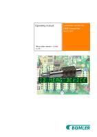
DESCRIPTION The RWP55 Series hydraulic pumps are designed to have a maximum of 690 bar (10,000 psi) at a flow rate of 902 cc/min (55 cu. in/min) maximum. Configurations, accerrories and pneumatic plumbing will reduce this value. All pumps come fully assembled, less fluid, and ready for work.
RWP55-BS Series Air/Hydraulic Pumps RWP55-4-BS Series Air/Hydraulic Pumps The air/hydraulic versions of the RWP55-4-BS Series start under full load and are suitable for operation up to 345 or 690 bar (5,000 or 10,000 psi). The pump has a 2.2 Kw (3 HP) air-driven motor at 3,000 RPM (optimum performance based on 5.5 bar (80 psi) air pressure and 1.4 M3/min. (49 CFM) at the pump). •
Minimum 9.5 L (2.5 Gal) reservoir.
•
Two-speed operation for rapid operation.
Note: The air supply must be minimum 1.4 M3/min. (49 CFM) and 5.5 bar (80 psi), with 7 bar (100 psi) the maximum. Use of an air filter/ lubricator is recommended. 5.5 bar (80 psi) air supply is required to start the pump under full load.
Figure 1. Air Pump (RWP55-4-BS Shown)
© 2014 SPX CORPORATION
3
Form No. 1000680 Rev. 1 June 17, 2014
CONTROL VALVES
Max. Capacity: 690 bar (10,000 psi) Valve Function
Run
RWP55-4-BS
OFF
Port “A”
Port “B”
T
P
From Pump
Port “A”
To Tank
Torque Wrench only NOT FOR LIFTING
3000167BK 4-way, 3-position Directional Valve
Diagrams
Port “A”
Port “B”
T
P
T
From Pump
Valve No.
Stop Port “B”
P
Used with
To Tank
From Pump
To Tank
Valve Function
Used with
Valve No.
Torque Wrench only NOT FOR LIFTING
3000273BK 4-way, 3-position Directional Valve
Diagrams Run
RWP55-BS
Port “A”
P
From Pump
OFF Port “B”
T
To Tank
Port “A”
Stop Port “B”
T
P
From Pump
To Tank
Port “A”
P
From Pump
Port “B”
T
To Tank
Table 1. Pump Configurations
© 2014 SPX CORPORATION
4
Form No. 1000680 Rev. 1 June 17, 2014
SAFETY SYMBOLS AND DEFINITIONS The safety signal word designates the degree or level of hazard seriousness.
DANGER: Indicates an imminently hazardous situation which, if not avoided, will result in death or serious injury.
WARNING: Indicates a potentially hazardous situation which, if not avoided, could result in death or serious injury.
CAUTION: Indicates a potentially hazardous situation which, if not avoided, may result in minor or moderate injury.
CAUTION: Used without the safety alert symbol indicates a potentially hazardous situation which, if not avoided, may result in property damage. IMPORTANT: Important is used when action or lack of action can cause equipment failure, either immediate or over a long period of time.
SAFETY PRECAUTIONS WARNING: • The following procedures must be performed by qualified, trained personnel who are familiar with this equipment. Operators must read and understand all safety precautions and operating instructions included with the pump. If the operator cannot read these instructions, operating instructions and safety precautions must be read and discussed in the operator's native language. • These products are designed for general use in normal environments. These products are not designed for lifting and moving people, agri-food machinery, certain types of mobile machinery, or in special work environments such as: explosive, flammable, or corrosive. Only the user can decide the suitability of this product in these conditions or extreme environments. Bolting Systems will supply information necessary to help make these decisions. Consult your nearest Bolting Systems facility. • Safety glasses must be worn at all time by the operator and anyone within sight of the unit. Additional personal protection equipment may include: face shield, goggles, gloves, apron, hard hat, safety shoes, and hearing protection. • The owner of this tool must ensure that safety-related decals are installed, maintained, and replaced if they become hard to read. • Shut OFF the motor before opening any connections in the system. • The guide cannot cover every hazard or situation so always do the job with SAFETY FIRST.
Pump WARNING: • Do not exceed the hydraulic pressure rating noted on the pump nameplate or tamper with the internal high pressure relief valve. Creating pressure beyond rated capacities can result in personal injury. • Retract the system before adding fluid to prevent overfilling the pump reservoir. An overfill can cause personal injury due to excess reservoir pressure created when cylinders are retracted. • The load must be under operator control at all times. © 2014 SPX CORPORATION
5
Form No. 1000680 Rev. 1 June 17, 2014
Safety Precautions continued • Do not connect pump to hydraulic system powered by another pump.
Air-Driven Motor WARNING: • Install a shut-off valve or quick disconnect in the air line to the motor. Close the shutoff valve before connecting the air line to the pump. • Read, understand, and follow the instruction manual for the air motor. • Disconnect the air supply and relieve pressure when the pump is not in use or when disconnecting any connection in the hydraulic system. • The control circuit must comply with local directives and standards.
Hoses WARNING: • Before operating the pump, tighten all hose connections using the correct tools. Do not overtighten. Connections should be only secure and leak-free. Overtightening can cause premature thread failure or high pressure fittings to split at pressures lower than their rated capacities. • Should a hydraulic hose rupture, burst, or need to be disconnected, immediately shut off the pump and shift the control valve twice to release pressure. Never attempt to grasp a leaking hose under pressure with your hands. The force of escaping hydraulic fluid could cause serious injury. • Do not subject the hose to potential hazard, such as fire, sharp surfaces, heavy impact, or extreme heat or cold. Do not allow the hose to kink, twist, curl, or bend so tightly that the fluid flow within the hose is blocked or reduced. Periodically inspect the hose for wear, because any of these conditions can damage the hose and possibly result in personal injury. • Do not use the hose to move attached equipment. Stress can damage the hose and possibly cause personal injury. • Hose material and coupler seals must be compatible with the hydraulic fluid used. Hoses also must not come in contact with corrosive material such as creosoteimpregnated objects and some paints. Consult the manufacturer before painting a hose. Never paint the couplers. Hose deterioration due to corrosive materials may result in personal injury. • Avoid straight line tubing connections in short runs. Straight line runs do not provide for expansion and contraction due to pressure and/or temperature changes. See diagrams in Initial Setup section of this form. • Eliminate stress in the tube lines. Long tubing runs should be supported by brackets or clips. Tubes through bulkheads must have bulkhead fittings. This makes easy removal possible and helps support the tubing. • Carefully inspect all hoses and fittings prior to use. Before each use, check entire hose for cuts, leaks, abrasion or bulging of cover, or damage or movement of couplings. If any of these conditions exist, replace the hose immediately. NEVER attempt to repair the hose.
© 2014 SPX CORPORATION
6
Form No. 1000680 Rev. 1 June 17, 2014
INITIAL SETUP 1. Remove all packing materials from the assembled unit. 2. Inspect the unit upon arrival. The carrier, not the manufacturer, is responsible for any damage resulting from shipment.
Filling the Pump Reservoir Most pumps are shipped without hydraulic fluid in the reservoir. Hydraulic fluid may have been shipped in a separate container, but if hydraulic fluid is needed, use only approved Power Team hydraulic fluid rated at AW 46 47 cSt @ 38°C (215 SUS @ 100°F) . If low temperature requirements are needed, use hydraulic fluid 5.1 cSt @ 100°C (451 cSt @ -40°C). 1. Clean the area around the filler cap to remove dust and grit. Debris in the hydraulic fluid can damage the polished surfaces and precision-fit components of this pump. 2. Remove the filler cap and insert a clean funnel with a filter. 3. Fill the reservoir with hydraulic fluid to 1.3-3.8 cm (0.5-1.5 in.) from the cover plate. 4. Replace the filler cap. Verify the breather-hole is open, if applicable.
Hydraulic Connections 1. Clean the areas around the fluid ports of the pump and tools. 2. Inspect all threads and fittings for signs of wear or damage, replace as needed. 3. Clean all hose ends, couplers or union ends. 4. Remove the thread protectors from the hydraulic fluid outlets. 5. Connect the hose assembly to the hydraulic fluid outlet, and couple the hose to the tool. CAUTION: To prevent personal injury from leaking hydraulic fluid, seal all hydraulic connections with a high-quality, non-hardening, pipe thread sealant. IMPORTANT: Sealant tape or non hardening sealer tape can be used to seal hydraulic connections if only one layer of tape is used. Apply tape carefully, two threads back, to prevent it from being pinched by the coupler and broken off inside the system. Loose pieces of sealant could travel through the system and obstruct the flow of fluid or cause jamming of precision-fit parts.
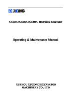
Rotary Air Motor Operation with Manual Valve The air supply must be minimum 1.4 M3/min. (49 CFM) and 5.5 bar (80 psi), with 7 bar (100 psi) the maximum. 1. Use of an air filter/lubricator is recommended but not supplied. Air motors could be shipped with the hand control valve installed. See Figure 4, for a typical air supply connection with air filter/ lubricator assembly. If the pump is operated on a continuous duty cycle, or at maximum speeds for extended periods, install an automatic air line oiler in the air inlet line as close to the pumping unit as possible. Set the oiler to feed 1–3 drops of SAE No. 10 oil per minute into the system (one drop for every 1.4-2.1 M3/ min. (49-75 CFM) of air), or refer to the air motor manufacturer’s instructions. 2. Place the valve in the neutral position. 3. See Figure 2. Couple the air motor to the air supply, and turn on the air supply valve (if provided). 4. Open (or turn on) the air supply control valve at the pump (hold-to-run hand control is provided). © 2014 SPX CORPORATION
7
Form No. 1000680 Rev. 1 June 17, 2014
Initial Setup continued 5. See Figure 2. Shift the pump as necessary.
8
6. Turn off the pump when not in use. 7. Start the pump and inspect for leaks or loose connections.
6
7
5
8. Operate the hydraulically driven device several times until it operates smoothly and consistently throughout the cycle.
4 2
9. Allow the pump to build pressure in the system. Stop pump and check each hose, fitting, and other system components for fluid leakage. If leakage is found, correct the problem and retest. 10. Turn off pump and check hydraulic fluid level. Add hydraulic fluid if needed.
3
1 i
Item
Description
1
Air Supply
2
Filter
3
Lubricator
4
Coupler
5
Hose
6
Hand or Foot Control (hand control shown)
7
Reducing Bushing
8
Air Motor
Figure 2. Typical Air Supply Connections Bleeding Air from the System After all connections are made, the hydraulic system must be bled of any trapped air. With no load on the system and the pump vented and positioned higher than the hydraulic device, cycle the system several times. Check the reservoir fluid level and fill to proper level with Power Team hydraulic fluid as necessary. If there is a problem contact the Power Team.
© 2014 SPX CORPORATION
8
Form No. 1000680 Rev. 1 June 17, 2014
OPERATING INSTRUCTIONS 1. Bleeding Air from the System 1. Cycle the hydraulic system until operation is smooth and consistent. 2. Check the pump reservoir level. Add Power Team hydraulic fluid as needed.
2. Air Motor Operation 1. Connect the air supply line. 2. The remote hand control has two momentary push buttons, advance and retract, with spring offset to hold. Press push buttons accordingly.
Figure 3. Air Pendant Control
3. Adjusting the Pressure Regulating Valve (if equipped). All others are factory preset. Note: For easy adjustment of the pressure regulating valve, always adjust the pressure by increasing to the desired pressure setting. 1. Loosen the locknut on the pressure regulating valve. Note: • The pressure range is from 69-690 bar (1,000-10,000 psi), depending on the pump model. 2. Use a screwdriver to back out the adjusting screw a few turns in a counterclockwise direction. This decreases the setting to a lower-than-desired pressure. 3. Air - The pump must be completely connected. Connect the pump to the appropriate air source and start the pump. 4. With the screwdriver, slowly turn the adjusting screw in a clockwise direction. This gradually increases the pressure setting. When the desired pressure is reached, lock the adjusting screw in position by tightening the locknut.
© 2014 SPX CORPORATION
9
Form No. 1000680 Rev. 1 June 17, 2014
PERFORMANCE SPECIFICATIONS The information in the following charts can be used as a basis to determine if the system is performing as expected during operation. Pump
RPM
RWP55-4-BS RWP55-BS
3,000
Amp Draw at Amp Draw at 690 bar (10,000 690 bar (10,000 psi) (115V) psi) (230V) N/A
dB A at Idle and 690 bar (10,000 psi)
Air Supply Req'd bar (psi)
85/90
2-9 bar (40-120 psi)
N/A
* Requires 1.4 M3/min. (49 CFM) at 5.5 bar (80 psi) shop air pressure at pump.
Table 2. Drive Unit Requirements
Pump
Max. Pressure Output bar (psi)
RWP55-4-BS RWP55-BS
690 bar (10,000 psi)
Fluid Delivery** (cu. in./min. @) 0 bar (0 psi)
7 bar (100 psi)
50 bar (700 psi)
70 bar (1,000 psi)
345 bar (5,000 psi)
690 bar (10,000 psi)
465
450
-
80
70
55
* Requires 1.4 M3/min. (49 CFM) at 5.5 bar (80 psi) shop air pressure at pump. ** Typical delivery. Actual flow varies with field conditions.
Table 3. Fluid Pressure Chart
© 2014 SPX CORPORATION
10
Form No. 1000680 Rev. 1 June 17, 2014
GENERAL MAINTENANCE WARNING: • Disconnect the unit from the power supply before performing maintenance or repair procedures. • Repairs and maintenance are to be performed in a dust-free area by a qualified technician.
1. System Evaluation The components of your hydraulic system — tools, pumps, hoses, and couplings — all must be: • Rated for the same maximum operating pressure. • Correctly connected. • Compatible with the hydraulic fluid used. A system that does not meet these requirements can fail, possibly resulting in serious injury. If you are in doubt about the components of your hydraulic system, contact Power Team Technical Support.
2. Inspection Keep a dated and signed inspection record of the equipment. Before each use, the operator or other designated personnel should visually inspect for the following conditions: • Excessive wear, bending, damage, or insufficient thread engagement. • Leaking hydraulic fluid. • Incorrectly functioning or damaged heads and caps. • Loose bolts or cap screws. • Damaged or incorrectly assembled accessory equipment. • Modified, welded, or altered equipment. • Bent or damaged couplers or port threads.
3. Periodic cleaning
WARNING: Contamination of the hydraulic fluid could cause the valve to malfunction. Loss of the load or personal injury could result.
Establish a routine to keep the hydraulic system as free from debris as possible. • Seal unused couplers with dust covers. • Keep hose connections free of debris. Equipment attached to a tool must be kept clean. • Keep the breather-hole in the filler cap clean and unobstructed. • Use only Power Team hydraulic fluid. Replace hydraulic fluid as recommended, or sooner if the fluid becomes contaminated. Never exceed 300 hours of use between fluid changes.
4. Hydraulic Fluid Level 1. Check the fluid level in the reservoir after each 10 hours of use. The fluid level should be 1.3 cm (0.5 in.) from the top of the fill hole when all cylinders are retracted. 2. Drain, flush, and refill the reservoir with an approved Power Team hydraulic fluid after every 300 hours of use. The frequency of fluid changes depends upon general working conditions, severity of use, the overall cleanliness and care given to the pump. Fluid should be changed more frequently when the system is not operated regularly indoors.
© 2014 SPX CORPORATION
11
Form No. 1000680 Rev. 1 June 17, 2014
General Maintenance continued 5. Draining And Flushing The Reservoir
2
1. Clean the pump exterior before the pump interior is removed from the reservoir. 2. Remove and discard the screws fastening the motor and pump assembly to the reservoir. Caution: Do not damage the pump filter or pressure regulating valves when lifting the pump and motor off the reservoir. See Figure 4. 3. Clean the inside of the reservoir, and fill with Power Team hydraulic fluid. Rinse the filter clean.
3 1
4. Place the pump and motor assembly back onto the reservoir, and secure with two machine screws assembled on opposite corners of the housing. 5. Refer to priming procedure. Place the hydraulic flow control valve in the neutral position. If the pump is equipped with a valve that has only an advance or retract position, place the valve in the advance position, and connect a hose to the advance port on the valve. Place the other end of the hose into the fluid filler plug hole. 6. Run the pump for several minutes.
4 Item
Description
1
Pressure Regulating Valve
2
Accumulator (not used on all models)
3
High Pressure Relief Valve
4
Filter
Figure 4. Pump Assembly
7. Disconnect the motor and pump assembly, and drain and clean the inside of the reservoir. 8. Fill the reservoir with Power Team hydraulic fluid. 9. Place the pump and motor assembly (with new gasket) on the reservoir, and install the new screws. 10. Tighten screws securely and evenly.
6. Adding Hydraulic Fluid To The Reservoir 1. Retract the cylinder(s) devices. 2. Disconnect the power supply. 3. Clean the entire area around the filler plug. 4. Remove the filler plug, and install a clean funnel with a filter. 5. Use only Power Team hydraulic fluid AW 46 47 cSt @ 38°C (215 SUS @ 100°F) . If low temperature requirements are needed, use hydraulic fluid 5.1 cSt @ 100°C (451 cSt @ -40°C).
7. Lubrication (Air Driven Motor Only) If the pump is operated on a continuous duty cycle, or at maximum speeds for extended periods, install an automatic air line oiler in the air inlet line as close to the pumping unit as possible. Set the oiler to feed 1–3 drops of SAE No. 10 oil per minute into the system (one drop for every 1.4-2.1 M3/min. (49-75 CFM) of air), or refer to the air motor manufacturer’s instructions.
© 2014 SPX CORPORATION
12
Form No. 1000680 Rev. 1 June 17, 2014
General Maintenance continued 8. Hose Connections CAUTION: To prevent personal injury from leaking hydraulic fluid, seal all hydraulic connections with a high-quality, non-hardening, pipe thread sealant. IMPORTANT: Sealant tape or non-hardening sealer tape can be used to seal hydraulic connections if only one layer of tape is used. Apply tape carefully, two threads back, to prevent it from being pinched by the coupler and broken off inside the system. Loose pieces of sealant could travel through the system and obstruct the flow of fluid or cause jamming of precision-fit parts.
9. Storage Store the unit in a dry, well-protected area where it will not be exposed to corrosive vapors, dust, or other harmful elements. If a unit has been stored for an extended period of time, it must be thoroughly inspected before it is used.
10. Hydraulic Schematic 6
5
4
L.P.
H.P.
7 8 3 2
2 1
A
1
3
B
9
12
15
10
14
Item
11
13
16 Description
Item
Description
1
Air Supply
9
Hydraulic 4-way 3-Position Directional Valve
2
Filter/Regulator/Lubricated (FRL)
10
Customer Tool
3
Cooler
11
4
Air motor
Retract Port Relief Valve and Shut-off 103 Bar (1,500 psi)
5
Unloading valve 69 Bar (1,000 psi)
12
Air Piloted 4-way 2-Position Directional Valve
6
Supercharge Valve 12 Bar (175 psi)
13
3-way Air Valve
7
Internal Relief Valve 717 Bar (10,400 psi)
14
Air Remote
8
External Relief Valve
15
Stop
16
Run
Figure 5. Hydraulic Schematic © 2014 SPX CORPORATION
13
Form No. 1000680 Rev. 1 June 17, 2014
TROUBLESHOOTING GUIDE WARNING:
• Repair work or troubleshooting must be performed by qualified personnel who are familiar with this equipment. • Check for system leaks by using a hand pump to apply pressure to the suspect area. Watch for leaking fluid and follow it back to its source. Never use your hand or other body parts to check for a possible leak. Notes: • For a detailed parts list or to locate a Power Team Authorized Hydraulic Service Center, contact your nearest Bolting Systems facility. • Plug the outlet ports of the pump when checking for leakage to determine if the leakage is in the pump or in the tool.
Problem
Cause
Solution
Pump delivers excess fluid 1. Faulty pressure gauge. pressure. 2. Relief valve set incorrectly. Pump is not delivering fluid, or delivers only enough fluid to advance connected components partially or erratically or operation to slow.
© 2014 SPX CORPORATION
1. Replace gauge. 2. Contact a Bolting Systems Service Center. 1. Fluid level too low. 1. Add fluid, refer to filling the pump reservoir in Initial Setup section. 2. Loose-fitting coupler to 2. Verify quick-disconnect couplings to component. tools are completely coupled. Couplers may need to be replaced because ball check does not stay open due to wear. 3. Air in system. 3. Refer to Initial Setup in this manual to bleed air from system. 4. Air leak in suction line. 4. Check and tighten suction line. 5. Debris in pump or filter plugged. 5. Clean pump filter. If problem persists, disconnect from power supply contact authorized Power Team service center. 6. Fluid bypasses through the tool. 6. Remove tool; cap hoses. Check pump and valve for leaks. 7. Cold fluid or fluid too heavy. 7. Drain, flush, and refill reservoir (Hydraulic fluid is of a higher using a lighter weight fluid. Refer to viscosity than necessary.) General Maintenance section. 8. External relief valve or low 8. Refer to Adjusting the Pressure pressure unloading valve out of Regulating Valve. adjustment. 9. Power unit/reservoir capacity is 9. Use smaller tool(s) or larger too small for the size of the tool(s) reservoir. used. 10. Vacuum in reservoir. 10. Clean plugged vent in filler plug.
14
Form No. 1000680 Rev. 1 June 17, 2014
Troubleshooting Guide continued Problem Pump builds pressure but cannot maintain pressure.
Cause 1. Fluid leakage.
Pump does not build to full 1. Faulty pressure gauge. pressure. 2. Check for external leakage.
Erratic action
3. Check external pressure regulator. Check relief valve setting. 4. Look for internal leakage in tools. 5. Inadequate air pressure for air motor operation. 1. Air in system. 2. Internal leakage in attached components. 3. Attached component sticking or binding. 4. Malfunctioning valve.
© 2014 SPX CORPORATION
15
Solution 1. Look for external leaks. If no fluid leakage is visible, the problem is internal. If using a double-acting tool, remove it from the system to ensure the leak is not in the tool. Seal leaking pipe fittings with pipe sealant. 1. Replace pressure gauge. 2. Seal faulty pipe fittings with pipe sealant. 3. Refer to Adjusting the Pressure Regulating Valve. 4. Remove tool from pump. If pump builds full pressure, tool is defective. 5. Refer to Initial Setup section. 1. Check for leaks. Refer to bleeding procedure. 2. Refer to manufacture's information for attached component. 3. Refer to manufacture's information for attached component. 4. Verify connections. Contact authorized Power Team Service Center.
Form No. 1000680 Rev. 1 June 17, 2014
PARTS LISTS
* 72
1
10
2X 49
52
48
2X 7 53 24
6
35
9X 3 43
15 51
22
44 71
67 13 50
69
21
55
5
57
4 25
63
27
38
26
70 30
39 58
19 8
40
32
14
46
62
2X 12
37
20
34
33
3X 45 65 17
29
31
60
18
47 11
23 16
64
2X 61
59
4X 66 54
56
2X
6X 36
2
3X 42
3X
68
9
41
3X 28
Figure 6. General Assembly Views (RWP55-4-BS-R Shown)
© 2014 SPX CORPORATION
16
Form No. 1000680 Rev. 1 June 17, 2014
Parts Lists continued
ITEM NO. 1 2 3 4 5 6 7 8 9 10 11 12 13 14 15 16 17 18 19 20 21 22 23 24 25 26 27 28 29 30 31 32 33 34 35 36 37 38
PART NUMBER 9072 10020 10177 10396 10442 10479 10575 10618 10623 10645 12328 12367 12825 13269 13966 14281-1 14281-2 14281-3 14281-4 14680 14725 15883 16494 16495 17147 17634 17636 18841 19463 40164 46626 65599BK2 203769 203770 205505 208218 212404 212896
© 2014 SPX CORPORATION
DESCRIPTION GAUGE, 10000 PSI, 4” DIA, CAL. (SPX) SCREW, SOCKET HD CAP SCREW. RND 1/4-20 X 0.75 NUT, JAM, 3/4-16 UNF WASHER, PLAIN 0.25X0.37X0.03 COPR FITTING, PLUG - 1/4 NPTF SCREW, DRIVE RD 2 X 0.19 STD B18.6.4 FITTING, TEE 1/4 NPTF M X (2) 1/4 NPTF F FITTING, TEE 3/8 NPTF M X (2) 3/8 NPTF F FITTING, 45D ELB 1/4 NPTF M X 1/4 NPTF F FITTING, STR 1/4 NPTF M X 3/8 NPT M CLAMP, HOSE 11/16-1 1/4 WORM DRIVE SCREW, HEX CAP 1/4-20 X 0.63 FITTING, REDUCING 1/4 TO 1/8 MUFFLER TUBING TUBING TUBING TUBING FITTING, 90D ELB 1/8 NPTF M x 1/8 NPTF F O-RING (-119) 0.924ID X 0.103 NITRILE 70 TUBING FITTING, STR 1/4 NPTF M X 1/4 NPTF M 1.3 FITTING, TEE 1/4 NPTF F x (2) 1/4 NPTF M FITTING, PLUG 7/16-20 ORB HEX FITTING, STR 1/4 NPTF M X 3/8 TUBE FITTING, 90D ELB 1/2 NPTF M X 3/8 TUBE FITTING, STR 1/8 NPTF F x 1/8 NPTF F FITTING, TEE 1/8 NPTF M X (2) 1/8 NPTF F GASKET, RESERVOIR RECT COIL, HEAT EXCHANGER TANK PT 02.00 GAL ALUM BLK VERT WELD 11 DECAL, LABEL STOP DECAL, LABEL RUN DEFLECTOR, MUFFLER FITTING, STR 1/8 NPTF M x 1/8 NPSM F VALVE, AIR OPERATED 3 WAY GROMMET, RUBBER 5/8 ID 17
QTY. 1 2 9 1 1 1 2 1 1 1 1 2 1 1 1 1 1 1 1 1 1 1 1 1 1 1 1 3 1 1 1 1 1 1 1 6 1 1
Form No. 1000680 Rev. 1 June 17, 2014
Parts Lists continued
39 40 41 42 43 44 45 46 47 48 49 50 51 52 53 54 55 56 57 58 59 60 61 62 63 64 65 66 67 68 69 70 71 72
212897 FITTING, 90D ELB 1/2 NPTF M x 5/8 HOSE 212898 HOSE, PRESSURE 213343 COUPLER, QUICK “PLUG HALF” (MALE) 213344 COUPLER, FEMALE QUICK, FOSTER 2202 250463 FITTING, 90D ELB 1/8 NPTF M x 1/4 TUBE 250643 FITTING, STR 1/2 NPT M x 1/2 NPT M 1.81” 250726 FITTING, STR 1/8 NPTF M X 1/8 TUBE 250804 FITTING, ELBOW 90 DEGREE 251206 COUPLING 251410 COUPLER, QUICK 251411 COUPLER, QUICK PLUG 251906 PLATE, PRODUCT NAME 252240 FITTING, STR 1/2 BSPP F X 1/2 BSPP F 252364 CAP, DUST 252365 CAP, DUST 253490 FITTING, 90D ELB 3/8 NPTF M x 1/2 TUBE 260108 FITTING, 90D ELB 1/2 NPTF M x 1/2 TUBE 350244 MANIFOLD 350431 GAUGE, FLUID LEVEL 351000 DRAIN 420096 HOSE, THREE STRAND 25’ 421265 CONTROL, AIR OPERATED HAND 1000543 DECAL, SPX BOLTING SYSTEMS 2000383 VALVE, AIR OPERATED 3-WAY 2000397 TUBE 2001448 TUBING, POLYURETHANE 1/2”O.D. X .086 WALL 2001792 FITTING, 90 DEGREE ELBOW 2001841 FITTING, 90 DEGREE ELBOW 2002032 WASHER, FLAT 1.12 IN X .85 X .12 SS 3000761 ROLL CAGE, AIR • (ONLY ON MODELS “RWP55-BS-R” AND “RWP55-4-BS-R”) 3000762 ASSY, AIR MTR W/FRL BRKT, NO HANDLE • 3000764 (ON “RWP55-BS” AND “RWP55-4-BS”) 3000769 COVERPLATE ASS’Y • 3000767 (ON “RWP55-BS” AND “RWP55-4-BS”) G4-1002-03 PACKING PLUG 1/2 NPT 2008281 FITTING, EXTENDER • (ONLY ON MODELS “RWP55-BS” AND “RWP55-4-BS”)
© 2014 SPX CORPORATION
18
1 1 3 3 1 1 3 1 1 1 2 1 1 1 1 1 1 1 1 1 1 1 2 1 1 1 1 4 1 1 1 1 1 1
Form No. 1000680 Rev. 1 June 17, 2014
Parts Lists continued 3X 24
31
120°
30
C
32
C
25
21
B
A
14
29
17 26 23
22 27
18
20
5
2X 2
12 3X 3
19 8
A
10
11 3X
16
1 28 3X 4
12
6
7
B 13 8 9
15
Figure 8. Cover Plate Assembly Side View #3000769 © 2014 SPX CORPORATION
19
Form No. 1000680 Rev. 1 June 17, 2014
Parts Lists continued
ITEM NO. 1 2 3 4 5 6 7 8 9 10 11 12 13 14 15 16 17 18 19 20 21 22 23 24 25 26 27 28 29 30 31 32
PART NUMBER 10008 10015 10016 10245 10266 10430 10431 10661 11173 11278 11421 14844 15456 16177 18841 21277-2 21278-15 21345 21943 41065-2 200415 200609 201570 251279 251689 252117 252118 351095 2000481BK2 3000239 3000768 3000770 • 3000273BK
© 2014 SPX CORPORATION
DESCRIPTION SCREW, SHC 1/4-20 X 0.75 SCREW, SHC 1/4-28 x 1.00 SCREW, SHC 1/4-20 x 1.00 WASHER, LOCK 0.490 x0.260 O-RING (-010) 0.239IDX0.070 NITRILE 70 TUBE,SLEEVE 3/8 DIA. FITTING, NUT 5/8-18 F (3/8 OD TUBE) FITTING, STR 1/4 NPTF M x 3/8 TUBE FITTING, STR 1/8 NPTF M x 3/16 TUBE FITTING, 90D ELB 1/8 NPTF M x 3/16 TUBE FITTING, STR 1/8 NPT M x 1/8 NPT M 1.0” FITTING, STR 1/8 NPTF M x 7/16-20 M FITTING, STR 1/8 NPT M x 1/8 NPT M 2.5” FITTING, 90D ELB 1/8 NPTF M x 3/16 TUBE FITTING, STR 1/8 NPTF F x 1/8 NPTF F VALVE, CHECK AND 10,000 PSI RELIEF VALVE, RELIEF 1500 PSI SCREEN, FILTER ACCUMULATOR PUMP BASIC PACKING, O’RING (SQUARE SECTION) TUBE, DRAIN .50 OD X 6.00 TUBE, PRESSURE REGULATOR FITTING, PLUG 1/8 PTF CAP, FILLER BREATHER LINE, OIL LINE, OIL GASKET, VALVE PLATE, COVER (MACHINED) VALVE, PNEUMATIC 2P4W REGULATOR ASS’Y VALVE, DIR. - 3P4W (ON 3000769) VALVE, DIR. - 3P3W (ON 3000767)
20
QTY. 3 2 3 3 1 2 1 1 1 1 1 1 1 1 1 1 1 1 1 1 1 1 1 2 1 1 1 1 1 1 1 1
Form No. 1000680 Rev. 1 June 17, 2014
Parts Lists continued
2
1
3
6
4
120°
5
12
10
11
9
8
7
Figure 10. Direction Valve #3000239
ITEM NO.
PART NO.
QTY
1
351232
1
SPOOL VALVE
2 3 4 5 6 7 8 9 10 11 12
421249 351231 16686 252105 15697 11195 10304 251279 10268 10301 3000167BK
1 1 1 1 1 1 2 2 1 1 1
VALVE BODY PISTON RETAINING RING PISTON PLASTIC CAP SPRING O-RING NITRILE PLUG 1/8 INCH O-RING NITRILE O-RING NITRILE SOLENOID VALVE 3-WAY
© 2014 SPX CORPORATION
DESCRIPTION
21
NOTES Pin supplied with spool valve. The pin holds the spool inside #12 to the air piston #3 (no part number)
Form No. 1000680 Rev. 1 June 17, 2014
Parts Lists continued
1 9
14
A
13
6 7
11 8
A 10
2
4
B
5
3 12
B A
Figure 11. Pressure Regulator #3000768
ITEM NO. 1 2 3 4 5 6 7 8 9 10 11 12 13 14
PART NUMBER 10266 10396 14874 215428 215429 215430 215431 215683 215693 309077 309079 350944 420891 2008429
© 2014 SPX CORPORATION
DESCRIPTION O-RING (-010) 0.239IDX0.070 NITRILE 70 NUT, JAM, 3/4-16 UNF WASHER, PLAIN RETAINER, SPRING SPRING, COMPRESSION WASHER, O’RING BACK-UP (SOLID) SPRING, SPACER Regulator Locking Nut T-HANDLE, PLASTIC Regulator Housing POPPET, REGULATOR FITTING SEAT BODY, REGULATOR ROD, ADJUST 10IN X .37 ST
22
QTY. 1 1 1 2 1 2 1 1 1 1 1 1 1 1
Form No. 1000680 Rev. 1 June 17, 2014
Parts Lists continued
1
25 19
26
20
2
27
21 22
3 4
23
5 6
28
13
7 8
24
14
9
30
10 15
11
31
16 8 7 8
29
32
13 33
17
12
20
27 26
18
12
Figure 12. Basic Pump Assembly #41065-2
© 2014 SPX CORPORATION
23
Form No. 1000680 Rev. 1 June 17, 2014
Parts Lists continued ITEM NO.
PART NO.
QTY
1
10020
9
SCREW, 1/4-20 X 1.25
2 3 4 5 6 7 8 9 10 11 12 13 14 15 16 17 18
33113 10361 10375 23547 23548 11228 11813 11814 23549 11955 11064 11261 23556 11821 23557 30533 10001
1 1 1 1 1 2 3 1 1 1 2 2 1 1 1 1 12
HIGH PRESSURE PUMP SPRING COMPRESSION STEEL BALL BEARING TOP PLATE TOP PLATE THRUST BEARING BEARING RACE BALL BEARING 10 DEGREE ANGLE PLATE SPRING SLOTTED PIN NEEDLE BEARING EXTERNAL RETAINING RING SHAFT WOODRUFF KEY DRIVE GEAR PUMP END PLATE SCREW, #10-32 X 1.75
19 20 21 22 23 24 25 26 27 28 29 30 31 32 33
21091 11199 10266 40120 10427 21272 10303 10425 20771 10271 12389 20849 23255 10426 23256
1 2 1 1 1 1 1 2 2 1 1 1 1 1 1
DRIVE COUPLING NEEDLE BEARING O-RING PUMP - MACHINE BODY PIPE PLUG DRIVE GEAR O-RING SPRING COMPRESSION POPPET O-RING BACKUP WASHER SPOOL SPRING GUIDE SPRING COMPRESSION SPRING GUIDE
200423 200645
1 2
SHIM - 0.065/0.070 THICK SHIM - 0.020 THICK
© 2014 SPX CORPORATION
DESCRIPTION
NOTES Torque to 19-20 Nm (170-180 in-lbs).
Torque to 6-7 Nm (50-60 in-lbs).
PARTS INCLUDED BUT NOT SHOWN
24
Form No. 1000680 Rev. 1 June 17, 2014
Parts Lists continued
6 1
7
2 5
8
2X SCALE 3 4
9
5
10
5
4 11
2X SCALE
3
Figure 13. High Pressure Pump Assembly #33113
© 2014 SPX CORPORATION
25
Form No. 1000680 Rev. 1 June 17, 2014
Parts Lists continued ITEM NO.
PART NO.
QTY
1 2
10442 10002
1 1
COPPER WASHER SOC. HD. CAP SCREW
3 4 5 6
*24549 *10445 *12223 *10023
6 6 7 7
VALVE GUIDE COMPRESSION SPRING STEEL BALL SOC. HD. CAP SCREW
7 8
*50411 10519
1 1
TOP PLATE SOC. SET SCREW
DESCRIPTION
NOTES Torque to 16-18 Nm (140-160 in-lbs.).
See Bolt Tightening Sequence Torque to 1920 Nm (170-180 in-lbs.). Torque to 7-8 Nm (65-70 in-lbs.).
9 *40630 1 VALVE HEAD 10 *41062 1 PUMP BARREL 11 *21628 3 PISTON *Consult factory when replacing items marked with an asterisk (*).
Bolt Tightening Sequence See Figure 14. Assemble in sequence shown. Lubricate under head and on threads. Torque to 20.5 Nm (180 in. lbs). 4 6
2
1
3 5
7
Figure 14. High Pressure Pump Assembly
© 2014 SPX CORPORATION
26
Form No. 1000680 Rev. 1 June 17, 2014
Parts Lists continued
17
1
1 2
2
3
1
4
3
5
4
6 6 7
8
16
9
15
14
13 12
11
10
Figure 15. Air Motor Assembly #3000764 (Shown) #3000762 (On "RWP55-BS" AND "RWP55-4-BS")
© 2014 SPX CORPORATION
27
Form No. 1000680 Rev. 1 June 17, 2014
Parts Lists continued ITEM NO.
PART NO.
QTY
1 2 3 4 5 6 7 8 9 10 11 12 13 14 15 16 17
10018 10174 33808 2001662 2007903 12719 F7-5022-38 250485 2008427 17816 37842 10556 30650 10008 51158WH2 14717 28158
5 2 2 2 1 13 4 4 1 4 1 1 1 4 1 1 1
© 2014 SPX CORPORATION
DESCRIPTION HEX SCREW ROUND SCREW HANDLE BRACKET HANDLE BRACKET SPACER FRL MOUNTING BRACKET PLAIN STEEL WASHER STEEL LOCK WASHER SCREW, #10-32 X 2.75 SHC F-R-L ASS'Y, RWP-BS SCREW, SHC 3/8-16 X 3.00 SHAFT EXTENSION SET SCREW MOTOR BASE GASKET SCREW, SHC 1/4-20 X 0.75 MOTOR BASE AIR MOTOR CROSS BAR HANDLE
28
NOTES NOT ON 3000762 NOT ON 3000762 NOT ON 3000762
Install from underside.
NOT ON 3000762
Form No. 1000680 Rev. 1 June 17, 2014
Parts Lists continued 1
3
2
4
5
6 8
9
7
10 11
3
2
12
Figure 16. Hand Control #421265 ITEM NO. 1 2 3 4 5 6 7 8 9 10 11 12
PART NO.
QTY
421265 203769 203770 208218
1 1 1 6
420096
1
206105 11033 206104 44024
2 2 2 1
© 2014 SPX CORPORATION
DESCRIPTION
NOTES
AIR OPERATED HAND CONTROL LABEL STOP DECAL LABEL RUN DECAL STRAIGHT FITTING RUN AIR LINE THREE STRAND 25' HOSE STOP AIR LINE MAIN AIR LINE PUSH W/WRENCH BUTTON INTERNAL RETAINING RING 3 WAY CLOSED CARTRIDGE VALVE VALVE BODY 29
Form No. 1000680 Rev. 1 June 17, 2014
Parts Lists continued 1 45
2
44
A
3 4
43 5
42
2 6 7 8
41 SECTION A-A
A
9
11
12
13
10 38 37
39
40
27 28
26
14
29 30
15
25
36
16
24
35
31 32
17
23 22
21
6 7
19
18
20
34 33
Figure 17. Valve #3000167BK
© 2014 SPX CORPORATION
30
Form No. 1000680 Rev. 1 June 17, 2014
Parts Lists continued ITEM NO.
PART NO.
QTY
1 2 3 4 5 6 7 8
22070 11284 10362 209541 12391 10266 12184 2002148
4 8 4 4 8 5 5 2
PISTON O-RING SPRING COMPRESSION PLAIN STEEL WASHER BACKUP WASHER O-RING BACKUP WASHER SPOOL POPPET
9 10 11 12 13
10269 10268 11863 21094 14426
1 4 4 2 4
O-RING O-RING BACKUP WASHER BUSHING SCREW, SHC 10-24 X 1.00
14 15 16 17 18
12042 10361 12955 10375 251279
1 1 1 1 1
PLAIN COPPER WASHER SPRING COMPRESSION DOWEL PIN STEEL BALL PLUG FITTING
19 20
351200 212735
1 1
REPLACEABLE SEAT SCREW, HOL LCK 5/8-18 X 0.31
21 22 23
252164 252099 252053
1 1 1
INSTRUCTIONS DECAL SPECIAL WASHER VALVE CAP
24 25 26
10383 351257 10854
1 1 2
HEX JAM NUT BUSHING SCREW, SHC 1/4-20 X 1.75
421856BK 251411 252365 251410 252364
8 1 4 4 4 4
COUPLERS, 1/4 NPTF MANIFOLD BODY QUICK PLUG COUPLER DUST CAP QUICK COUPLER DUST CAP
27 28 29 30 31 32
© 2014 SPX CORPORATION
DESCRIPTION
31
NOTES
Assemble in this end only.
Torque to 6-8 Nm (50-70 in-lbs.).
Torque to 14 Nm (120 in-lbs.). Torque to 34 Nm (300 in-lbs.).
Torque to 34 Nm (300 in-lbs.).
Torque to 19 Nm (165 in-lbs.).
Form No. 1000680 Rev. 1 June 17, 2014
Parts Lists continued ITEM NO.
PART NO.
QTY
33
10427
2
PLUG FITTING
34 35 36
10672 420902BK 11151
4 1 4
STRAIGHT FITTING LEFT END CAP SCREW, SHC 10-24 X 1.25
37
10479
1
PLUG FITTING
38 39 40 41 42 43 44 45
1400-AA 65095BK 64648BK 10265 10302 12392 2002146 2002147
1 1 1 6 4 4 4 2
1/4 PLASTIC PACKAGING PLUG VALVE BODY RIGHT END CAP O-RING O-RING BACKUP WASHER SEAT CARTRIDGE ACTUATOR SPOOL
© 2014 SPX CORPORATION
DESCRIPTION
NOTES Torque to 28 Nm (250 in-lbs.).
32
Torque to 6-8 Nm (50-70 in-lbs.). Torque to 6 Nm (50 inlbs.).
Assemble in this end only.
Form No. 1000680 Rev. 1 June 17, 2014
Parts Lists continued 1 44
2
43
3
A
4
42 5
41
2 6 7 8
40 SECTION A-A
A
9
11
12
13
10 37
38
39
36
14
27
28
15
26
35
16
25 29 30
34
17
24 23
22
6 21
33
19
18
20
31 32
22
Figure 18. Valve #3000273BK
© 2014 SPX CORPORATION
33
Form No. 1000680 Rev. 1 June 17, 2014
Parts Lists continued ITEM NO.
PART NO.
QTY
1 2 3 4 5 6 7 8
22070 11284 10362 209541 12391 10266 12184 2002148
4 8 4 4 8 5 4 2
PISTON O-RING SPRING COMPRESSION PLAIN STEEL WASHER BACKUP WASHER O-RING BACKUP WASHER SPOOL POPPET
9 10 11 12 13
10269 10268 11863 21094 14426
1 4 4 2 4
O-RING O-RING BACKUP WASHER BUSHING SCREW, SHC 10-24 X 1.00
14 15 16 17 18 19 20
12042 10361 12955 10375 251279 351200 212735
1 1 1 1 1 1 1
PLAIN COPPER WASHER SPRING COMPRESSION DOWEL PIN STEEL BALL PLUG FITTING REPLACEABLE SEAT SCREW, HOL LCK 5/8-18 X 0.31
21 22 23 24
12184 252164 252099 252053
1 1 1 1
BACKUP WASHER INSTRUCTIONS DECAL SPECIAL WASHER VALVE CAP
25 26 27 28 29 30 31 32 33
10383 351257 14972 351319BK 251411 252365 251410 252364 10854
1 1 1 1 4 4 4 4 2
HEX JAM NUT BUSHING PLUG FLUSH FITTING MANIFOLD BODY QUICK PLUG COUPLER DUST CAP QUICK COUPLER DUST CAP SCREW, SHC 1/4-20 X 1.75
34
420902BK
1
LEFT END CAP
© 2014 SPX CORPORATION
DESCRIPTION
34
NOTES
Assemble in this end only.
Torque to 6-8 Nm (50-70 in-lbs.).
Torque to 34 Nm (300 in-lbs.).
Torque to 34 Nm (300 in-lbs.).
Torque to 17-20 Nm (150-180 in-lbs.).
Form No. 1000680 Rev. 1 June 17, 2014
Parts Lists continued ITEM NO.
PART NO.
QTY
35
11151
4
SCREW, SHC 10-24 X 1.25
36 37 38 38 39 40 41 42 43 44
10479 1400-AA 10479 65095BK 64648BK 10265 10302 12392 2002146 2002147
3 1 1 1 1 6 4 4 4 2
PLUG FITTING 1/4 inch 1/4 PLASTIC PACKAGING PLUG PLUG FITTING VALVE BODY RIGHT END CAP O-RING O-RING BACKUP WASHER SEAT CARTRIDGE ACTUATOR SPOOL
DESCRIPTION
PARTS INCLUDED BUT NOT SHOWN 10970
© 2014 SPX CORPORATION
2
NOTES Torque to 6-8 Nm (50-70 in-lbs.).
Assemble in this end only.
PLUG FITTING
35
Form No. 1000680 Rev. 1 June 17, 2014
Parts Lists continued
8X
4
2X
1
2X 3
4X 5
1X
2
Figure 19. Roll Cage, Air #3000761
ITEM NO. 1 2 3 4 5
PART NUMBER 1000464 2001573GR15 2001597 2001612 2001650
© 2014 SPX CORPORATION
DESCRIPTION DECAL, SPX BOLTING SYSTEMS ROLL CAGE, ISP AIR (GREEN) PLATE, ROLL CAGE NAME SCREW, M8-1.25 X 10mm BHC SCREW, 1/2-20 X.75 UNF BHC STL BOX
36
QTY 2 1 2 8 4
Form No. 1000680 Rev. 1 June 17, 2014
Power Team Facilities
© 2014 SPX CORPORATION
37
Form No. 1000680 Rev. 1 June 17, 2014
Declaration of Conformity
© 2014 SPX CORPORATION
38
Form No. 1000680 Rev. 1 June 17, 2014