![EDC [PDF]](https://pdfs.asia/img/200x200/edc.jpg)
18 0 2 MB
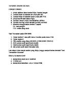
These PowerPoint color diagrams can only be used by instructors if the 3rd Edition has been adopted for his/her course. Permission is given to individuals who have purchased a copy of the third edition with CD-ROM Electronic Materials and Devices to use these slides in seminar, symposium and conference presentations provided that the book title, author and © McGraw-Hill are displayed under each diagram.
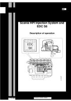
Silicon is the most important semiconductor in today’s electronics |SOURCE: Courtesy of IBM
200 mm and 300 mm Si wafers. |SOURCE: Courtesy of MEMC, Electronic Materials, Inc.
GaAs ingots and wafers. GaAs is used in high speed electronic devices, and optoelectronics. |SOURCE: Courtesy of Sumitomo Electric Industries, Ltd.
ψhyb orbitals
Si crystal in 2-D
Electron energy Ec +χ
Valence electron
CONDUCTION BAND (CB) Empty of electrons at 0 K.
Ec ψB
Bandgap = Eg Ev VALENCE BAND (VB) Full of electrons at 0 K.
Si ion core (+4e) 0
(a)
(b)
(c)
(a) A simplified two dimensional illustration of a Si atom with four hybrid orbitals, ψhyb. Each orbital has one electron. (b) A simplified two dimensional view of a region of the Si crystal showing covalent bonds. (c) The energy band diagram at absolute zero of temperature.
Fig 5.1 From Principles of Electronic Materials and Devices, Third Edition, S.O. Kasap (© McGraw-Hill, 2005)
A two dimensional pictorial view of the Si crystal showing covalent bonds as two lines where each line is a valence electron. Fig 5.2 From Principles of Electronic Materials and Devices, Third Edition, S.O. Kasap (© McGraw-Hill, 2005)
Electron energy Ec+χ CB Ec hυ > Eg Ev
Free e-
hυ
Eg Hole
hole
e-
VB 0
(a)
(b)
(a) A photon with an energy greater than Eg can excite an electron from the VB to the CB. (b) When a photon breaks a Si-Si bond, a free electron and a hole in the Si-Si bond is created. Fig 5.3
From Principles of Electronic Materials and Devices, Third Edition, S.O. Kasap (© McGraw-Hill, 2005)
eh+
Thermal vibrations of atoms can break bonds and thereby create electronhole pairs. Fig 5.4 From Principles of Electronic Materials and Devices, Third Edition, S.O. Kasap (© McGraw-Hill, 2005)
e
-
h
(a)
CB
+
h
+
h
+
Eg
h
+
(d)
VB
h
h
+
h
(b)
e
+
+
e
-
eÐ
h
+
(e)
-
(c)
h
+
h
+
A pictorial illustration of a hole in the valence band wandering around the crystal due to the tunneling of electrons from neighboring bonds. Fig 5.5 From Principles of Electronic Materials and Devices, Third Edition, S.O. Kasap (© McGraw-Hill, 2005)
(f)
Ex
Hole energy
(a)
Electron Energy
V(x)
Electrostatic PE(x)
Ex CB CB
(b) VB VB
x x=0
x=L
When an electric field is applied, electrons in the CB and holes in the VB can drift and contribute to the conductivity. (a) A simplified illustration of drift in Ex. (b) Applied field bends the energy bands since the electrostatic PE of the electron is -eV(x) and V(x) decreases in the direction of Ex whereas PE increases. Fig 5.6 From Principles of Electronic Materials and Devices, Third Edition, S.O. Kasap (© McGraw-Hill, 2005)
E g(E)
E c+ χ
(E-Ec)1/2
E
E
[1- f(E)]
CB
For electrons
Area = n
Ec
Ec
nE(E)
EF
EF
Ev
Ev For holes
VB 0 (a)
g(E) (b)
f(E) (c)
pE(E) Area = p
nE(E) or pE(E) (d)
(a) Energy band diagram. (b) Density of states (number of states per unit energy per unit volume). (c) Fermi-Dirac probability function (probability of occupancy of a state). (d) The product of g(E) and f(E) is the energy density of electrons in the CB (number of electrons per unit energy per unit volume). The area under nE(E) vs. E is the electron concentration in the conduction band. Fig 5.7 From Principles of Electronic Materials and Devices, Third Edition, S.O. Kasap (© McGraw-Hill, 2005)
CB Ec EFi Ev
Ec EFn
Ec
Ev
EFp Ev
VB
(a)
(b)
(c)
Energy band diagrams for (a) intrinsic (b) n-type and (c) p-type semiconductors. In all cases, np = ni2 Fig 5.8 From Principles of Electronic Materials and Devices, Third Edition, S.O. Kasap (© McGraw-Hill, 2005)
From Principles of Electronic Materials and Devices, Third Edition, S.O. Kasap (© McGraw-Hill, 2005)
As+ e-
Arsenic doped Si crystal. The four valence electrons of As allow it to bond just like Si but the fifth electron is left orbiting the As site. The energy required to release to free fifth-electron into the CB is very small. Fig 5.9 From Principles of Electronic Materials and Devices, Third Edition, S.O. Kasap (© McGraw-Hill, 2005)
Electron Energy
CB Ec ~0.03 eV Ed
As+
As+
As+
As+
Ev As atomsites every 106 Si atoms
x Distance into crystal
Energy band diagram for an n-type Si doped with 1 ppm As. There are donor energy levels just below Ec around As+ sites. Fig 5.10 From Principles of Electronic Materials and Devices, Third Edition, S.O. Kasap (© McGraw-Hill, 2005)
h+
B-
B-
Free
(a)
(b)
Boron doped Si crystal. B has only three valence electrons. When it substitutes for a Si atom one of its bonds has an electron missing and therefore a hole as shown in (a). The hole orbits around the B- site by the tunneling of electrons from neighboring bonds as shown in (b). Eventually, thermally vibrating Si atoms provides enough energy to free the hole from the B- site into the VB as shown. Fig 5.11 From Principles of Electronic Materials and Devices, Third Edition, S.O. Kasap (© McGraw-Hill, 2005)
Electron energy B atom sites every 106 Si atoms
x Distance
Ec
into crystal
B-
Ea
B-
B-
B~ 0.05eV
h+ Ev
VB
Energy band diagramfor a p-type Si doped with 1 ppmB. There are acceptor energy levels just above Ev around B- sites. These acceptor levels accept electrons fromthe VB and therefore create holes in the VB. Fig 5.12 From Principles of Electronic Materials and Devices, Third Edition, S.O. Kasap (© McGraw-Hill, 2005)
From Principles of Electronic Materials and Devices, Third Edition, S.O. Kasap (© McGraw-Hill, 2005)
V(x) x Electrostatic PE(x) = -eV
Electron Energy Ex
Ec Ed EF
EFi
Ev n-Type Semiconductor A
B V
Energy band diagram of an n-type semiconductor connected to a voltage supply of V volts. The whole energy diagram tilts because the electron now has an electrostatic potential energy as well
Fig 5.13 From Principles of Electronic Materials and Devices, Third Edition, S.O. Kasap (© McGraw-Hill, 2005)
T < Ts
Ts < T < Ti
T > Ti
CB EF As+ As
As
Eg
As
+ + EF As As+ As+ As
EF
As+ As+ As+ As+
VB
(a)T=T1
(b)T=T2
(c)T=T3
(a) Below Ts, the electron concentration is controlled by the ionization of the donors. (b) Between Ts and Ti, the electron concentration is equal to the concentration of donors since they would all have ionized. (c) At high temperatures, thermally generated electrons from the VB exceed the number of electrons from ionized donors and the semiconductor behaves as if intrinsic. Fig 5.14 From Principles of Electronic Materials and Devices, Third Edition, S.O. Kasap (© McGraw-Hill, 2005)
ln(n) INTRINSIC slope = -Eg/2k
ln(Nd)
EXTRINSIC
Ts
IONIZATION slope = −ΔE/2k
Ti ni(T)
1/T
The temperature dependence of the electron concentration in an n-type semiconductor. Fig 5.15 From Principles of Electronic Materials and Devices, Third Edition, S.O. Kasap (© McGraw-Hill, 2005)
600oC 400oC L
L
200oC
27oC 0oC
L
L
Intrinsic Concentration (cm-3)
1018
2.4×1013 cm-3 1015
Ge 1012
1.45×1010 cm-3
109
Si 106
2.1×106 cm-3
GaAs 103
1
1.5
2.5 3.5 3 4 1000/T (1/K) The temperature dependence of the intrinsic concentration. 2
Fig 5.16 From Principles of Electronic Materials and Devices, Third Edition, S.O. Kasap (© McGraw-Hill, 2005)
e-
KE = 1/2mev2
KE > |PE| KE ≈ |PE|
rc As+ KE < |PE|
Scattering of electrons by an ionized impurity Fig 5.17 From Principles of Electronic Materials and Devices, Third Edition, S.O. Kasap (© McGraw-Hill, 2005)
Electron Drift Mobility(cm2 V-1s-1)
50000
μL∝T -1.5
10000
Nd
=1014
Ge Nd =1013
Nd =1016 Nd =1017
1000
Nd =1018 100
Nd
Si
=1019
μΙ ∝T1.5
10 70
100
Temperature (K)
800
Log-log plot of drift mobility vs temperature for n-type Ge and n-type Si samples. Various donor concentrations for Si are shown. Nd are in cm-3. The upper right inset is the simple theory for lattice limited mobility whereas the lower left inset is the simple theory for impurity scattering limited mobility. Fig 5.18
From Principles of Electronic Materials and Devices, Third Edition, S.O. Kasap (© McGraw-Hill, 2005)
Drift Mobility(cm2 V-1s-1)
2000 1000
Holes
Electrons
100 50 1015
1016
1017
1018
1019
1020
Dopant Concentration, cm-3 The variation of the drift mobility with dopant concentration in Si for electrons and holes Fig 5.19 From Principles of Electronic Materials and Devices, Third Edition, S.O. Kasap (© McGraw-Hill, 2005)
INTRINSIC
Resistivity
LOGARITHMIC SCALE
log( )
Semiconductor
Metal
log(n)
T
EXTRINSIC Lattice scattering
IONIZATION μ∝T
log( )
-3/2
3/2
μ∝T Impurity scattering
1/T
High Temperature
Low Temperature
Temperature dependence of electrical conductivity for a doped (ntype) semiconductor. Fig 5.20 From Principles of Electronic Materials and Devices, Third Edition, S.O. Kasap (© McGraw-Hill, 2005)
E Impurities forming a band g(E)
CB
CB
EFn Ec
Ec Ev EFp
Ev
VB (a)
(b)
(a) Degenerate n-type semiconductor. Large number of donors form a band that overlaps the CB. (b) Degenerate p-type semiconductor. Fig 5.21 From Principles of Electronic Materials and Devices, Third Edition, S.O. Kasap (© McGraw-Hill, 2005)
Energy CB Ec
ψcb(kcb)
hυ = Eg
ψvb(kvb) Ev
VB
Distance
Direct recombination in GaAs. kcb = kvb so that momentum conservation is satisfied Fig 5.22 From Principles of Electronic Materials and Devices, Third Edition, S.O. Kasap (© McGraw-Hill, 2005)
CB Ec Er Ev
Er
Er
Phonons
Recombination center
VB
(a) Recombination CB Ec
Ev
Et
Et
Et
Trapping center
VB
(b) Trapping Recombination and trapping. (a) Recombination in Si via a recombination center which has a localized energy level at Er in the bandgap, usually near the middle. (b) Trapping and detrapping of electrons by trapping centers. A trapping center has a localized energy level in the band gap. Fig 5.23 From Principles of Electronic Materials and Devices, Third Edition, S.O. Kasap (© McGraw-Hill, 2005)
CB Ec Ed
Ev VB Low level photoinjection into an n-type semiconductor in which Δnn < nno Fig 5.24
From Principles of Electronic Materials and Devices, Third Edition, S.O. Kasap (© McGraw-Hill, 2005)
Low level injection in an n-type semiconductor does not affect nn but drastically affects the minority carrier concentration pn. Fig 5.25 From Principles of Electronic Materials and Devices, Third Edition, S.O. Kasap (© McGraw-Hill, 2005)
Illumination
B
A -
-
-
- + - -- - - - + - - - --
-
+ -
- + - + + +- + - - + -+ - + - + - - + - - + + - + - + - - - + -+ + -
≈ n-type semiconductor in Illumination with hυ >Eg the dark. creates excess holes: pn = pno