![Equipment Preservation Procedure [PDF]](https://pdfs.asia/img/200x200/equipment-preservation-procedure.jpg)
5 0 500 KB
NITROGEN BLANKETTING PROCEDURE 1) Ensure all the equipment nozzles were completely blinded and required nozzles with the provision of nitrogen blanketing setup / Pneumatic test 2) Pneumatic test to be done before preservation of equipment with Nitrogen blanketing. (Max pressure of 0.5 bar based on design pressure of equipment) 3) Before purging out the equipment ensure the both inlet and outlet valve under open condition 4) Connect the nitrogen hose with proper clamping in inlet port of the equipment and ensure the outlet port of the valve under open condition 5) Two pressure gauge to be provided in the system (Inlet and outlet port of the equipment side) and critical equipment should be provided with safety valve if required. 6) Slightly open the nitrogen cylinder regulator isolation valve and ensure the nitrogen flow comes out in outlet Port of the equipment 7) Ensure the pressure reads in both (inlet /outlet) pressure gauge. Kept the cylinder regulator isolation valve under some constant opening.(constant flow) 8) Adjust the inlet valve up to 0.1bar, purge out system for 15 minutes 9) By adjusting inlet/outlet valve slowly pressurized (up to 0.2bar based upon design pressure of the equipment )and depressurized the system for two or three times to excavate the oxygen content in the system 10) Check the oxygen content in outlet port .If oxygen content above 10% again 15- 20mins purging to be started until the oxygen content reads below 2%. 11) Once oxygen content reads below 2%, slowly closed the inlet and outlet valve with blanketing pressure of 0.2 bar. 12) Disconnect the hose from the system and provide the end cap for both inlet /outlet port 13) Noted down the pressure which reads in inlet/ outlet pressure gauge, After 4 hrs once
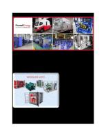
we cross check the pressure with blanketing pressure. 14) Schematic diagram for nitrogen blanketing setup shown below
SCEHMATIC DIAGRAM FOR NITROGEN BLANKETTING SETUP ,