![Highway Subdrainage Design FHWA [PDF]](https://pdfs.asia/img/200x200/highway-subdrainage-design-fhwa.jpg)
13 0 13 MB
Publication
U.S.Department of Transportation Federal Highway Administration
Highway Subdrainage
-.
No.
FHWA-TS-80-224
(Reprinted
Design
August july
1980 1990)
PREFACE
The author wishes to express his sincere appreciation to the Federal Highway Administration and the many individuals and agencies that provided assistance during the preparation of this Manual. In particular, the author wishes to thank Mr. Edwin Granley of the Implementation Division of the Office of Development of FHWA, who served as project manager throughout the project. His patience and understanding will long be remembered. The successful completion of this Manual would not have been possible without the wholehearted cooperation and technical assistance of Mr. George W. Ring of the Pavement Systems Group of the Structures and Applied Mechanics Division of the FHWA Office of Research. His continued support and encouragement are very much appreciated. The author is very grateful to the members of the Transportation Research Board Committee A2K06 on Subsurface Drainage for their support of this project, for their review of the manuscript and their valuable suggestions. The contribution of the many other reviewers of the manuscript is also gratefully acknowledged. Finally, the author Linda Sutherland for her manuscript of the Manual.
wishes untiring
to
express efforts
his appreciation in the preparation
to Mrs. of the
NOTICE This document is disseminated under the sponsorship of the Department of Transportation in the interest of information exchange. The United States Government assumes no liability for its contents or use thereof. The contents of this report reflect the views of the Office of Development of the Federal Highway Administration, which is responsible for the facts and the accuracy of the data presented herein. The contents do not necessarily reflect the official views or policy of the Department of Transportation. This report or regulation.
does
not
constitute
a standard,
specification,
The United States Government does not endorse products or manufacturers. Trade or manufacturers' names appear herein only because they are considered essential to the object of this document.
Report
No.
FHWA-TS-80-224
HIGHWAY SUBDRAINAGE DESIGN
Lyle K. Moulton, Ph.D., P.E. Professor of Civil Engineering West Virginia University and
TRIAD
Principal Engineering Morgantown,
Engineer Consultants, West Virginia
Sponsored
Inc.
by
Federal Highway Administration Offices of Research and Development Washington, D.C. 20590
Auoust
1980
SUMMARY
Chapter
I - General
Considerations
This Chapter is devoted of subsurface water, the movements, and the types be used either singly or (Pages l-40)
Chapter
II
- Data
to a general discussion of the adverse effects types and sources of subsurface water and its of subsurface drainage installations that can in combination, to control this water.
Required
for
Analysis
Lists the data requirements for mended procedures for assembling
Chapter
III
- Pavement
Presents methods and infiltration
Chapter
Chapter
more
V - Construction
and data.
Design design and presents (Pages 41-58)
recom-
Drainage
and recornnended criteria in pavement structural
IV - Control
Deals with the (Pages 114-140)
analysis these
and
of
for the sections.
control (Pages
of groundwater 60-113)
Groundwater
general
control
of
groundwater
away
from
the
pavement.
and Maintenance
Presents a discussion of the construction and maintenance aspects of subdrainage systems. Recornnendations are presented for construction techniques designed to insure that the subsurface drainage systems will actually function in the manner in which they were designed to function. Chapter V also presents recomnendations for maintenance procedures designed to insure that subsurface drainage systems continue to perform satisfactorily for the life of the facility. In addition, the utilization of subsurface drainage for remedial purposes or in connection with pavement rehabilitation is discussed. (Pages 141-153)
TABLE OF CONTENTS Page List
of Tables
List
of Figures
. . . . . . . . . . . . . . . . . . . . . . . .
vii
.......................
Chapter I - GENERALCONSIDERATIONS.............. 1.1 - Introduction
1.2.1 1.2.2 1.2.3
1
. . . . . . . . . . . . . . . . . . . . .
1.2 - Adverse Effects
of Subsurface Water
. . . . . . . . .
.............. Stability of Slopes Pavement Performance .............. ............ Economic Considerations
1.3 - Occurrence and Movement of Subsurface 1.3.1 1.3.2 1.3.3
Water
.....
. . . . . . . . .
Classifications of Highway Subdrainage .............. Longitudinal Drains ............... Transverse Drains ............... Drainage Blankets Well Systems .................. Miscellaneous Drainage .............
.....
Chapter II - DATA REQUIREDFOR ANALYSIS AND DESIGN ...... 2.1 - General
. . . . . . . . . . . . . . . . . . . . . . .
2.2 - Geometry of Flow Domain 2.2.1 2.2.2
2.3.1 2.3.2
. . . . . . . . . . . . . . .
Highway Geometry ................ Subsurface Geometry ..............
2.3 - Properties
of Materials
iii
2
‘13 13 13 18 21 21 26 26 30 35 40 41 41 41 41 44
...............
................ Index Properties Performance Characteristics
1
3 3 13
Types of Subsurface Water . . . . . . . . . . . Sources of Subsurface Moisture . . . . . . . . . . . . Seepage (Movement) of Subsurface Moisture
1.4 - Type and Uses of Highway Subdrainage 1.4.1 1.4.2 1.4.3 1.4.4 1.4.5 1.4.6
vi
45 ..........
45 45
Table
of
Contents
(continued) Page
2.4
- Climatological 2.4.1 2.4.2
2.5
3.2
Precipitation Depth of Frost
- Miscellaneous
Chapter .3.1
III --
General
- Quantity
.................. Penetration
55 55
........... . . . . . . . . . . . . .
58
. . . . . . . . . . . . . . . .
60
. . . . . . . . . . . . . . . . . . . . . . .
61
to be Removed
. . . . . . . . . . . .
Infiltration .................. Groundwater .... ; .............. Melt Water From Ice Lenses ........... Vertical Outflow ................ Net Inflow ................... and Design
of Drainage
Layers
and Design
of
Collection
General Considerations Longitudinal Collectors Transverse Collectors Outlets .....................
Systems
. . . . . . . .
- General......................;.
4.2
- Longitudinal
4.3
- Multiple
4.4
- Symmetrical
4.5
- Miscellaneous
4.6
- Filter
. . . . . . .
103 103 104 110 111
............. ............. ..............
II4 114
Interceptor Interceptor Drawdown
Protection
87 87 98 101
IV - CONTROL OF GROUNDWATER . , 1 . . . , . . . , s . ,
4.1
61 61 63 68 73 84
Thickness and Permeability ........... Filter Requirements ............... Special Considerations .............
- Analysis 3.4.1 3.4.2 3.4.3 3.4.4
Chapter
55
Considerations
of Water
- Analysis 3.3.1 3.3.2 3.3.3
3.4
. . . . . . . . . . . . . . . . . .
- PAVEMENT DRAINAGE
3.2.1 3.2.2 3.2.3 3.2.4 3.2.5 3.3
Data
Drains
114
Drains
. . . . . . . . . . . . . .
123
Drains
. . . . . . . . . . . . . .
124
Groundwater in
............
Control
Groundwater
iv
Measures Control
. . . . . .
134
. . . . . . .
137
Table of Contents
(continued) Page
Chapter V - CONSTRUCTIONAND MAINTENANCE . . . . . . . . . . . . 141 5.1 - General
. . . . . . . . . . . . . . . . . . . . . ...141
5.2 - Construction 5.2.1 5.2.2
Operations
General Precautions . . . . . . . . . . . . . . . 141 Sequence of Construction Operations and Inspection . . . . . . . . . . . . . . . . . . . 143
5.3 - General Maintenance 5.3.1 5.3.2 5.3.3
. . . . . . . . . . . . . . . . 141
. . . . . . . . . . . . . . . . . . 144
........... Cleaning of Collector Pipes Maintenance of Outlets .............. Miscellaneous Maintenance and Other Considerations .. .' ..............
5.4 - Subsurface
Drainage and Pavement Rehabilitation
REFERENCES...........................154
V
144 144 146 . . . . 146
LIST OF TABLES Page 1.
Typical
. . , . . . . . . . . .
47
7-.
Approximate correlation between permeability and Unified Soil Classification (59) . . . . . . . . . . . .
48
3.
Average values
49
I -I.
Guidelines for selection of heave rate or frost susceptibility classification for use in Figure
5.
values
of soil
of soil
permeability
permeabilities
(50)
. . . . . . . . 38
. . .
72
Guidelines forusing Equations (12) through (16) to compute net inflow, q , for design of pavement drainage . . . . . . .n. . . . . . . . . . . . . . . . .
86
6.
Summary of recommended inspection activities associated with subsurface drainage system installation . . . . . . . . . . . . . . . . . . . . . . 145
7.
Description of drainage problems in pavement rehabilitation and their possible solution (adapted from Ring (25)) . . . . . . . . . . . . . . . . . . . . . 151
vi
LIST OF FIGURES Page 1. 2.
3. 4.
5. 6. 7. 8. 9. 10. 11. 12. 13.
14.
Potentially controlled
Unstable Cut Slope Resulting From UnGroundwater Flow . . . . . . . . . . . . . .
4
Typical Cut Slope Failure - Secondary Route 6339, Moore County, Tennessee (Photo Courtesy of William D. Trolinger, Tennessee Department of Transportation) . .
5
Potentially Unstable Fill Slope Resulting From the Damming of Wet Weather Groundwater Flow . . . . . . . .
6
Typical Slope Failure in Sidehill Fill - State Route 30, Rhea County, Tennessee (Photo Courtesy of William D. Trolinger, Tennessee Department of Transportation)
.
7
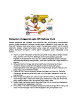
Action of Free Water in A. C. Pavement Structural Sections Under Dynamic Loading . . . . . . . . . . . .
8
Pumping Phenomena Under Portland Cement Concrete Pavements . . . . . . . . . . . . . . . . . . . . . . .
9
Capillary Moisture Migrating Toward Freezing Front To Feed The Growth of Ice Lenses . . . . . . . . . . .
11
Seepage of Meltwater Structural Section
From Ice Lenses Into Pavement . . . . . . . . . . . . . . . . . .
12
Capillary Moisture as a Function of The History of Watertable Position (28) . . . . . . . . . . . . . . .
14
Schematic Illustration in a Gravity-Flow
of the Occurrence of Groundwater System . . . . . . . . . . . . . . .
16
Schematic Illustration of the Occurrence of Groundwater in an Artesian System . . . . . . . . . . . . . . . . .
17
Points of Entrance of Water Into Highway Pavement Structural Sections . . . . . . . . . . . . . . . . .
19
Paths of Flow of Surface and Subsurface Water in Portland Cement Concrete Pavement Structural Sections . . . . . . . . . . . . . . . . . . . . . . .
22
Longitudinal Interceptor Drain Used to Cut Off Seepage and Lower the Groundwater Table . . . . . . . .
23
vii
List
of
Figures
(continued) Page
15. 16;
Symmetrical the Water
Longitudinal Drains Used to Lower Table . . . . . . . . . . . . . . . . . . e .
Longitudinal Seeping
Into
17.
Multiple,
Multipurpose,
18.
Multiple
19.
Transverse
Drains
20.
Transverse Cut With Contours
Zla.
to Remove Section
Longitudinal
Longitudinal
Drawdown
Water . . . . . . .
Drain
Drain
Installations
27
. . . .
28
. . . . . . . .
29
Interceptor Drain Installation in Roadway Alignment Perpendicular to Existing . . . . . . . . . . . . . . . . . . . . . . .
31
on Superelevated
Curve
32
Profile and Typical Section of Drainage Trench at Towle Slide (35) . . . . . . . . . . . . . . . . . .
33
22.
Applications
. . . . . .
35
23.
Drainage Blanket (Wedge) Longitudinal Collector
Slope Drained by . . . . . . . . . . . . .
36
Drainage Blanket Beneath Sidehill Fill Outletted by Collector Drain . . . . . . . . . . . . . . . . . . . .
37
25.
Well
. . . .
38
26.
Typical
. . . . . . . . .
40
27.
Path
28.
Chart For Granular
24.
29. 30. 31.
Showing Drainage Towle Slide (35)
Installation
25
Details and Boring Locations . . . . . . . . . . . . . . . . . .
21b.
Plan at
Collector Drain Used Pavement Structural
24
of
System
Horizontal
Used
for
Sand Drainage of
Typical Bases
Subsurface Estimating Drainage Gradations and Filter
Drainage on Cut Drain
Draining Well Water
Blankets
Unstable
Slope
Installation in
. . . . . . .
43
of Permeability of Materials . . . . . . . .
51
Drainage
Coefficient and Filter
(36)
of Open Graded . . . , . . . . . .
52
Determining Yield Capacity (Effective . . . . . . . . . . . . . . . . . . . . . . .
53
Summary of Results of All Standard Laboratory Freezing Tests Performed by the Corps of Engineers Between 1950 and 1970 (64) . . . . . . . e . . . . . a . . . .
64
Chart For Porosity)
and Permeabilities Materials (5,16)
Layer
viii
'.
List
of Figures
(continued) Page
The 1 Hour/l Year Frequency Precipitation Rates for the United States (66) . . . . . . . . . . . . . . .
56
33.
Maximum Depth of Frost Penetration in the United States (69) . . . . . . . . . . . . . . . . . . . . . .
57
34.
Rigid Pavement Section In Cut-Dimensions and Details for Examples 1, 3, 11, 13, 14 and 17 . . . . , . . . . .
64
Flexible Pavement Section In Fill - Dimensions and Details for Examples 2; 12 and 15. . . . . . . . . . . .
65
Chart for Determining Flow Rate in Horizontal Drainage Blanket . . . . . . . . . . . . . . . . . . . . . . . .
67
Artesian Flow of Groundwater Into a Pavement Drainage Layer - Dimensions and Details for Example 4 . . . . . .
69
38.
Chart for Estimating Design Inflow Rate of Melt Water From Ice Lenses . . . . . . . . . . . . . . . . . . . .
71
39.
Vertical
. . . . .
74
40.
Vertical Outflow Toward an Underlying Layer of Very High Permeability . . . . . . . . . . . . . . . . . . .
75
Vertical and Lateral and its Foundation
Outflow Through Embankment . . . . . . . . . . . . . . . . . . .
76
Transient Flow Net for the Case of Vertical Outflow Toward an Existing Horizontal Watertable - Dimensions and Details for Example 6 0 . . . . . . . . . . . . . .
78
Chart for Estimating Structural Section Sloping Underlying
Vertical Outflow From Pavement Through Subgrade Soil to a Watertable . . . . . . . . . . . . .
80
Chart for Estimating Vertical Outflow From a Pavement Structural Section Through the Subgrade to an Underlying High Permeability Layer . . . . .'. . . . . . . .
82
Chart for Estimating Structural Section Soil..........................
83
32.
35. 36. 37.
41. 42.
43.
44.
45.
Outflow
Toward An Underlying
Watertable
Vertical Outflow From a Pavement Through Embankment and Foundation
ix
List
of Figures
(continued) Page
Chart for Estimating Maximum Depth of Flow Caused by Steady Inflow (12) . . . . . . . . . . . . . . . . .
88
47.
Time Dependent Drainage of Saturated
Layer (27, 79) . . .
89
48.
Plan and Profile of Proposed Roadway - Dimensions and Details for Example 16 . . . . . . . . . . . . . . . .
93
Proposed Subsurface Drainage System for Flexible Pavement on Fill-Dimensions and Details for Example16 . . . . . . . . . . . . . . . . . . . . . .
94
Gradation Bands for Subbase, Drainage Layer, and Embankment Material - Examples 16 and 18 . . e . . . .
95
Layout of Proposed Drainage System Showing Direction of Flow in Drainage Layer - Details and Dimensions for Example16 . . . . . . . . . . . . . . . . . . . . . .
97
Gradation Bands for Subbase, Filter Layer and Subgrade - Example 17 . . . . . . . . . . . . . . . . . Material
100
Gradation Bands For Filter Layer and Embankment Material - Example 18 . . . . . . . . . . . . . . . . .
102
54.
Typical
Location
of Shallow Longitudinal
105
55.
Typical
Location
of Deep Longitudinal
. .
106
56.
Nomogram Relating Collector Pipe Size with Flow Rate, Outlet Spacing and Pipe Gradient - Adapted From Cedergren (5,16) . . . . . . . . . . . . . . . . . . .
108
57.
Recommended Detail
. . .
113
58.
Multiple
. . . . . . . . .
115
59.
Flow Toward a Single
. . . . . . . . .
116
60.
Flow Toward a Single Interceptor Drain When the Drawdown Can be Considered to be Insignificant at a Finite Distance, Li, from the Drain . . . . . . . . . .
118
46.
49.
50. 51.
52. 53.
Interceptor
for Outlet Drain
Collector
Pipes Pipes
Pipe and Marker (16)
Installation
Interceptor
Collector
Drain
/
I
List
of Figures
(continued) Page
61.
Chart for Determining
. .
120
62.
Chart for Determining Drawdown Curves for Interceptor Drains . . . . . . . . . . . . . . . . . . . . . . . .
121
63.
Example No. 21 - Flow Net, Dimensions
. . . .
122
64.
Example No. 22 - Dimensions and Details Required for the use of Figures 61 and 62. . . . . . . . . . . . . . . .
125
65.
Example No. 22 - Flow Net, Dimensions
. . . .
126
66.
Division of a Symmetrical Drawdown Drain Problem Into Two Equivalent Fragments . . . . . . . . . . . . .
128
Free Water Surfaces Based on Gilboy Modification of Dupuit Theory . . . . . . . . . . . . . . . . . . . . .
129
68.
Chart for Determining
Underdrains
131
69.
Chart for Determining the Maximum Height of Free Water Surface Between Symmetrical Underdrains . . . . . . . .
132
70.
Example No. 23 - Flow Net, Dimensions,
. . .
133
71.
(a) Cross-Section of Fill. Localized Surface Drains. (c) Draining a Group (b) Draining a Single Spring. of Springs. After Cedergren (11) . . . . . . . . . . .
136
Typical Filter Only Filter
138
67.
72. 73.
Typical Filter Coarse Filter
Flow Rate in Interceptor
and Details
and Details
Flow Rate in Symmetrical
System for Aggregates
Typical
75.
Installation
76.
Drains
77.
Combined Edge and Joint
and Details
Interceptor Drain Using . . . . . . . . . . . . . . . .
System for Interceptor Aggregate and Filter
74.
Drains
Components of Prefabricated of Prefabricated
at Cracks and Joints
,Drain Using Fabric . . . . . . . Fin Drains
Fin Drain
in Trench (96).
140
.
140
. . . . . . . . . . . .
149
(25) . . . . . . . . . . .
149
(25)
Drains
(96) . . .
138
xi
----^-
.--.--..- ......-__.
_
List
of Figures
(continued) Page
78. 79.
Utilizing New Edge and Lateral Drains With Existing Drain Pipe (25) . . . . . . . . . . . . . . .
150
Providing New Drainage Capabilities Through the Shoulder (25) . . . . . . . . . . . . . . . . . . . .
150
xii
METRIC CONVERSIONFACTORS Approximxto
symbbl
wbw
Convrcsions
VW Kww
:o Metric
Yllllipl~
Marsurrs
Approximrtr
#d,~~,E=~S
squua cm1ilm1rs 6.6 0.03 0.6 2.6 0.4
MASS
x-1. 4. -I.
01
MASS
(wright)
(mifiht)
lwmr
0.036 2.2 1.1
knl
02 lb
VOLUME
S 1s 30 0.24 0.47 0.96 3.6 0.03 0.76
TEMPERATURE
in’ rr’ nli*
hiMgums mules Iloo
VOLUME umpoms table-l livid -I cuw pinw Qurrs gallau cubic twt cubic yards
in in r vd mi
0.16 1.2 0.4 2.6
squu. mm,* square kilmatews kecu*s l10,ooo m?
28 0.46 0.9
lb
MIDSW~S
AREA
AREA upwmlndm 4--M vd* SquN. mitw MS
Yatric
0.06 0.4 3.3 1.1 0.6
cantimlus RlU@f‘ mu,* kilatrs
‘2.6 30 0.9 1.4
indw fnl v=d. mile4
fton
b1
LENGTH in II vd ni
Convrrsiors
milhlilws liters heiS liters cubic meters cubic meterr
milliliDrS milliliter* millilitatr IitsrS li:efs ,lU,l ,,,*,s cubtc meters cubic meters
0.03 2.1 1.04 0.26 36 1.3
II 01 P Q 011 fl’
vd’
TEMPERATURE
(oxrct)
(rxxct)
OF
32
96.6
*F a2
Chapter I - GENERALCONSIDERATIONS 1.1 - Introduction It would be difficult, if not impossible, to select the date when the early road builders first became aware of the need for adequate subsurface drainage. However, there is some evidence that this need was recognized almost as soon as formal road building began (1,2)l. Certainly, by the middle of the 18th Century, it was understood that appropriate subsurface drainage was absolutely necessary for the satisfactory The subsequent introduction of long term performance of roadways. "french drains" and the pavement systems of Tresaguet and MacAdam shows not only an understanding of the problem, but an attempt to incorporate into the roadway design formal measures for the satisfactory removal of water from the pavement structure and subgrade (2,3). In the years that have followed these early beginnings, the number of published accounts of research dealing with highway subsurface drainage has undergone a substantial growth (4,5). In addition, there has been a steady growth in the knowledge and availability of solutions to problems of fluid flow through porous media (6,7,8,9,10,11,12). Consequently, we now recognize and understand many of the problems that can be created by excessive subsurface moisture, and we have the means available to provide for the satisfactory control of this moisture. It is the purpose of this manual to provide the designer with the tools to analyze subdrainage problems and to design subsurface drainage facilities to adequately solve these problems. It is difficult to separate the design of subsurface drainage from In fact, it cannot, in the the design of other elements of a highway. final analysis, be eliminated from consideration with respect to the However, as far as. stability of slopes, design of pavements, etc. the assembly of data on highway geometry and material properties is Thus, it is recommended that concerned, we do need a starting point. the normal highway and pavement design practice be followed to develop general cross-sections, whether this involves individual detailed This will analysis and design or the utilization of design standards. yield a highway geometry and material properties that can then be subThis procedure jected to analysis and design for subsurface drainage. may result in some changes in the design in order to provide adequate drainage as recommended in this manual, but it is felt that this approach tends to be less confusing than attempting to incorporate detailed consideration of subsurface drainage into the design from It will also permit.the use of specialized personnel for the outset. the analysis and design of subsurface drainage, if this is considered /' to be desirable. 1Numbers in parenthesis on page 154.
refer
to the reference 1
list,
which begins
The remainder of Chapter I is devoted to a general discussion of the adverse effects of subsurface water, the types and sources of subsurface water and its movements, and the types of subsurface drainage installations that can be used either singly or in combination, to control this water. Chapter II lists the data requirements for analysis and design and presents recommended procedures for assembling these data. Chapter III presents methods and recommended criteria for the control of groundwater and infiltration in pavement structural Chapter IV deals with the more general control of groundsections. water away from the pavement, and Chapter V presents a discussion of the construction and maintenance aspects of subdrainage systems. Recommendations are presented for construction techniques designed to insure that the subsurface drainage system will actually function in the manner in which it was designed to function. Chapter V also presents recommendations for maintenance procedures designed to insure that subsurface drainage systems continue to perform satisfactorily for the life of the facility. In addition, the utilization of subsurface drainage for remedial purposes or in connection with pavement rehabilitation is discussed. Many of the techniques for the analysis and design of subdrainage systems have been simplified for inclusion in this manual, and considerable use is made of solutions in chart form. Examples are presented to illustrate the recommended analysis and design procedures and the use of the various charts. Although it is felt that the treatment of highway subsurface drainage in this publication is a comprehensive one, the infinite variety of seepage and drainage problems that can occur in nature is such that absolute coverage is impossible. The methods of analysis and design presented here are considered to be tools to aid in solving subsurface drainage problems - there are no standard solutions. The subdrainage problems encountered on each highway, or section of highway, will commonly be different and will require individual consideration and treatment. This manual can help in this regard, but it cannot substitute for the efforts of a well trained and experienced designer working with reliable field and laboratory data and exercising good engineering judgment. 1.2 - Adverse Effects
of Subsurface Water
Excessive and uncontrolled subsurface water is known or suspected to have been responsible for a very large amount of unsatisfactory highway performance and many outright failures (5). In general, these adverse effects of subsurface water can be placed in two general categories: (a) slope instability, including the sloughing and sliding of cut slopes and sidehill fills; and (b) unsatisfactory pavement perfor-
2
mance as manifested in premature asing roughness, and a relatively serviceability.
rutting, cracking, faulting, rapid decrease in the level
increof
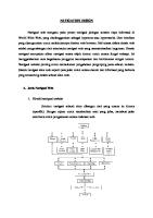
1.2.1 Stability of Slopes. Slope instability results when the applied shear stresses exceed the strength of the soil or rock mass along a potential sliding surface. Subsurface water can contribute to this instability by increasing the stress level and decreasing the shear strength. Seepage forces, resulting from the viscous drag that is created by the flow of water through a porous medium, can add substantially to the level of the stresses that must be resisted. At the porewater pressures within the slope reduce the the same time, thus reducing the effective level of effective normal stresses, The result could be minor slope sloughing or shear strength (11,13). a complete slope failure; Figure 1 shows schematically the development of one type of subsurface flow that can lead to cut slope instability. Figure 2 shows a typical cut slope failure for which the uncontrolled flow of groundwater was, at least partially, responsible. The manner in which a sidehill fill can function to dam the natural flow of groundwater is illustrated in Figure 3. This trapping of the groundwater can result in a loss of strength of the natural soil and/or the fill and lead to its ultimate collapse, as shown in Figure 4. 1.2.2 Pavement Performance. Excessive moisture in the pavement structure (surface, base and subbase) and the underlying subgrade can cause a wide variety of problems, leading to early pavement distress and ultimately to complete destruction of the pavement, if remedial measures are not undertaken. If the pavement structural section and subgrade can become satuits ability to transmit rated, by groundwater, and/or infiltration, the dynamic loading imposed by traffic can be greatly impaired (5,14, 15,16). In asphaltic concrete pavement systems, this impairment is primarily the result of the temporary development of very high pore water pressures and the consequent loss of strength in unbound base, subbase and subgrade under dynamic loading (5,16). This action is the preillustrated schematically in Figure 5. In some instances, ssures induced in the free water may be sufficient to cause it to be ejected through cracks in the pavement surface along with suspended ejection of water and fines, or pumping, can fines (5). A similar occur at the joints or edges of Portland cement concrete pavements, although the mechanism is different. Shortly after a Portland cement concrete pavement has been cornthat small spaces can exist under the joints pleted, it is possible because of the thermally induced upward curl of the pavement slabs (see Figure 6a). These spaces can become enlarged under the action 3
Original
Ground
Q
,-Proposed
f
Cut Slope
f
Drawdown Curve Potential Sliding
Figure
Surface
1.
Proposed Roadway
Original Watertable
of Seepage
Potentially Unstable Cut Slope Resulting From Uncontrolled Groundwater Flow
n
5
a
6
. U al
7
Direction
of Travel
Cracks Partially or Completely Filled with Water 1 \ I Asphalt Pavement (Flexible)
-. -L..:
. . L
., __ ,..o.;: -
., ;
\ -L--
\
Subgrade Soil (Saturated)
=Deflection
Unloaded A.C. Pavement
Loaded A.C. Pavement
1
Note:
Figure
5.
of Subgrade
Vertical dimensions of deformations are exaggerated for clarity.
Action of Free Water in A.C. Pavement Structural Sections Under Dynamic Loading (16)
Direction
.
Subgrade Soil (Saturated) Unloaded P.C.C. (a>
Note:
of Travel
(b) Direction
Pavement
Vertical dimensions of deformations are exaggerated for clarity.
:Ybe;q.
.d:.
Displaced -.&y+) ,:'::.: Water is Violently ,j-..~'TA,,-. -....xr.CJ'O-' Carrying Suspended Fines L:t ..
Loaded P.C.C.
Figure
6.
Pumping Phenomena Under Portland Cememt Concrete Pavements (16)
Pavement
of
Travel
;B.-.+,: :"d ,~~;~-Y: o-. ,;.a: f.- . 0 ..; .:0 .*':'
of traffic because of the localized compaction or permanent deformation of the underlying materials caused by slab deflection. When the base and subgrade are saturated and free water exists beneath the joint, an approaching wheel load causes the trailing edge of the slab to deflect downward (see Figure 6b), sending a fluid pressure wave or water jet in a forward direction. As the wheel passes over the joint, the trailing slab rebounds upward as the leading edge of the next slab is deflected downward (see Figure 6~). This results in erosion of material from under the leading edges, ejection of water and fines from the and the deposition of some material under the trailing edges joints, Should this pumping continue for any extended period of time, (17). faulting may occur and the pavement slabs may crack because of the lack of adequate support (5,16,18). Distress in pavement slabs can also be caused by pumping along the edges of the pavement. These phenomena have been studied extensively and, although a number of remedial measures have been suggested, it appears that the most effective approach to the problem is to prevent the accumulation of water beneath the pavement slabs by means of a combination of effective joint seals and subsurface drainage (5,16). Another adverse effect that uncontrolled moisture can have on pavement systems results from the several phenomena which are collectively referred to as frost action (19,20). Frost action requires the presence of a readily available supply of subsurface moisture, frost susceptible soils, and a sustained period of subfreezing temperatures. If all these requisites are satisfied, then moisture will migrate through the capillary fringe (Sec. 1.3) toward the freezing front to feed the growth of ice lenses, as illustrated in Figure 7. During the the growth of ice lenses can result in subactive freezing period, stantial heave of the overlying pavement structure. This can cause significant damage to a pavement, particularly if differential frost heaving is experienced. However, the most potentially destructive effect of frost action is associated with the loss of support during spring thaw. The thawing of the ice lenses leaves the subgrade soil resulting in a substantial resaturated, or possibly supersaturated, since the thawing generally takes duction in its strength. Moreover, can drain place from the top down, the only way the excess moisture from the subgrade soil is by flowing into any available voids that may exist in the pavement structural section, as shown in Figure 8. subbase) is not adequately drained, If the pavement structure (base, it may become saturated with the water being squeezed from the subgrade and the destructive mechanisms previously discussed (Figure 5 and 6) The resulting pavement deterioration is genmay become operative. erally referred to asspring breakup (19,20). The frequent or sustained presence of excess moisture in pavement components and intermittent exposure to cycles of freezing and thawing can result in the loss of structural integrity. In Portland cement concrete pavements containing certain aggregates, this may appear as D-cracking (21,22), and as stripping or accelerated weathering in bituminous mixtures (23). In either case there is evidence that excluding 10
---
Frost
.z--~ -
Susceptible Soil
Freezing -
~
-
t
t
t V - -
Figure
7.
t
i
Moisture Migration
t
Free Watertable
7
Capillary Moisture Migrating Toward Freezing To Feed The Growth of Ice Lenses
Front
Front
Seepage From Thawing Subgrade Soil Pavement Surface
Very Wet (Saturated)
Thawed Soil
Unfrozen
Figure
8.
Soil
Seepage of Meltwater From Ice Lenses Into Pavement Structural Section
Thawing From Bottom-Up
excess moisture or providing drainage can be beneficial
in
for its rapid removal with appropriate minimizing damage from these causes
(5).
1.2.3 Economic Considerations. In the preceding paragraphs, many of the adverse effects of excessive and uncontrolled subsurface water on highway performance have been discussed. However, in many the economic considerations can overshadow the physical instances, aspects of unsatisfactory highway performance. For example, in several areas of the United States, very large annual expenditures are required for remedial construction and maintenance connected with landslides In many cases, it has been found that uncontrolled subsur(13,24). face waters have played an important role in causing the failures. In most instances, the corrective measures have included the installation of some type of subsurface drainage (13,24). Although definitive records are rarely available, it is very likely that the lack of adequate subsurface drainage also leads to large annual expenditures for in the form of shortened life and increased maintenance pavements, and rehabilitation costs (5,16,25). The economic comparisons and cost-benefit analyses that are available have demonstrated that there can be a very substantial long term economic advantage in providing for adequate subsurface drainage where needed as part of the original design and construction (5,16). 1.3
- Occurrence
1.3.1 a variety capillary
and Movement
of
Subsurface
Types of Subsurface Water. of forms, including (a) water moisture, and (d) gravitational
Water vapor is saturation. Although studied extensively, mitted in the vapor not be given further
Water
Subsurface water can exist in vapor, (b) bound moisture (c) or free water (6,7,10,12).
generally present in the pores above the zone of water movement in the vapor phase has been for our purposes the total amount of water transphase can be considered negligible, and it will consideration.
Bound moisture is generally considered to be of two types: (a) hygroscopic (absorbed) moisture and (b) oriented (pellicular) water. Hygroscopic moisture is so tightly bound to the surface of the soil particles that it is considered to be immobile, and it can only be removed after being transformed into the vapor phase by some means, such as drying at elevated temperatures. The oriented moisture is not considered to be as tightly bound as hygroscopic moisture. Although it can be moved under the action of an attraction gradient, it will not flow under the force of gravity and, therefore, will not be given further consideration. Capillary moisture is water held in the pores of a soil above the level of saturation (water table, free water surface, or phreatic line) under the action of surface tension forces, as shown in Figure 9a. The height of the capillary fringe and the shape of the moisture-tension 13
n 0) r-4
14
curve is a function of the pore size distribution in the soil, which is related to its grain size distribution and density (26,27). Figure 9b shows that the degree of saturation resulting from capillarity is also a function of the history of the position of the water table (28). Direct consideration of this phenomenon in seepage analysis is difficult, but it can be considered indirectly by modifying the concept of porosity It is important to recognize that since capillary (see Sec. 2.3). moisture is held in the pores of the soil above the free water surface, it cannot be removed by gravity. Thus, against the force of gravity, the only means available for the control of capillary moisture are through lowering the water table with appropriate subdrainage or providing for a positive barrier (27) against capillary rise. Gravitational or free moisture is water to move under the free, as its name implies, hydraulically induced pressure gradients. It laws of fluid mechanics and hydraulics. The and it will be our primary concern hereafter, the subsurface drainage will be designed.
in liquid form that is force of gravity and/or will, therefore, obey the control of free water will be for this purpose that
1.3.2 Sources of Subsurface Water. The analysis and design of highway subsurface drainage systems involves the consideration of subsurface water from a wide variety of sources. However, it is convenient to consider these sources of drainable subsurface water in two broad general categories: (a) groundwater, which is defined as the water existing in the natural ground in the zone of saturation below the water table and (b) infiltration, which is defined (for the purposes of this publication) as surface water that gets into the pavement structural section by seeping down through joints or cracks in the pavement surface, through voids in the pavement itself, or from ditches along the side of the road. The main source of groundwater is precipitation, which may penetrate the soil directly or may enter streams, lakes or ponds and percolate from these temporary storage areas to become groundwater. This source may be supplemented by artificial recharge in the form of The occurrence of groundwater from these sources is irrigation. illustrated schematically in Figure 10. The groundwater shown in Figure 10 is part of a "gravity-flow system" in that one of the boundaries defining the flow domain is a free water surface. Another common occurrence of groundwater is in the "artesian system" as illustrated in Figure 11. Under these circumstances, a "perched" water table may exist and the water in the confined or partially confined aquifer may be under substantial fluid pressure. Although the free water from melting ice lenses Commonly exists above the water table, as shown in Figure 8, it is generally considered that this is groundwater. The water that feeds the growth of ice lenses originates at the base of the capillary fringe (i.e. at the water table), and no frost action could take place without water from this source. 15
Transpdratron /-Irrigation
Capillary
Fringe t
/-Influent
soi.1 moisture Moving DOWII After a Rain
Stream
Zone of Saturation
Figure
10.
Schematic Illustration of the Occurrence of Groundwater in a Gravity-Flow System
Wmdwater)
TNonflowing
Artesian /-
atertable
Well Recharge Area F.lowing Artesian
----
Well
Ground Surface
---Piezometric
WatercaDA=
Figure
11.
Schematic Illustration of the Occurrence of Groundwater in an Artesian System
The main source of water that infiltrates into the pavement Water that falls on the structural section is also precipitation. surface of the pavement shoulders or median can get into the pavement surface, base and subbase through a variety of entrance points as illustrated in Figure 12. In the case of concrete pavements, the greatest amount of infiltration would be expected to occur.along longitudinal and transverse construction joints and at the joints between the concrete slabs and the shoulders. However, as time goes additional infiltration may take place through cracks in the conon, crete slabs and shoulders (5,16,29). For bituminous pavements, the primary initial sources of infiltrationmay be along the longitudinal joints at the shoulders and the construction joints between strips of paving. Additional longitudinal and transverse cracking may occur after a time, even in well designed and constructed bituminous pavements, providing additional sources of infiltration (5,16,29). Moresome water may seep downward through voids in the pavement surover, face itself, although this is not commonly thought of as being one of the major sources of infiltration (29). The infiltration of water into the pavement structural section However, would appear, on the face of it, to be a simple phenomenon. the interaction between the type and frequency of openings permitting infiltration, the rate of water supply, and the permeability and ambient moisture conditions of the underlying materials is most complex. Thus, the estimation of the amount of infiltration that must be controlled by subsurface drainage requires careful consideration. This is discussed in greater detail in Section 3.2.1. 1.3.3 Seepage (Movement) of Subsurface Water. Generally, seepage is defined as the movement, or flow, of a fluid through a permeable porous medium. In particular, the fluid with which we are concerned is water, and the permeable porous media are soils, rock and the structural elements of pavements. The porosity is defined as the ratio of the volume of the pore spaces to the total volume of the material. The extent to which porous media will permit fluid flow, . its permeability, is dependent upon the extent to which the I.e., pore spaces are interconnected and the size and shape of the interconnections (10,30). Based on his classic experiments on the flow of water through sand filter beds, Darcy (31) concluded in 1856 that the flow of water through porous media is governed by a simple linear law (Darcy's Law), which is generally stated in the form V
where called . I.e.,
=
ki,
k is a constant v is the discharge velocity; the coefficient of permeability; and i is the ratio of change of total head, h, with 18
(1) of proportionality, the hydraulic gradient, respect to distance, s,
Direction
of Fl
Figure
12.
Points of Entrance Pavement Structural
of Water Into Highway Sections (16)
in the direction of flow. In its gradient can be expressed as
most general
form,
the hydraulic
although, quite commonly, the total derivative dh/ds, or the difference form Ah/As, is employed. Equation (1) can be put more useful form by multiplying by the cross-sectional area, flow domain. This yields an expression for the flow rate, q, form q
=
finite in a A, of the in the
kiA
(3)
The validity of Darcy's Law is known to be contingent upon the existence of laminar flow (10,27,30,32,33). For most natural soils and low permeability granular materials, this condition will be satisfied over a wide range of hydraulic gradients. However, for more open graded granular materials the flow may becomenonlaminar, even at relatively low hydraulic gradients (27,32,34). Under these circumstances, it is still possible to use Darcy's Law for practical seepage analysis if appropriate consideration has been given to this phenomenon in evaluating the coefficient of permeability. This is explained in greater detail in Section 2.3.2. It should be noted, at this stage, that the coefficient of permeability, upon which equations (1) and (3) depend, varies over a very wide range, depending on the nature of the porous media (see Sec. 2.3.2) through which flow is taking place. In natural deposits, and even in some compacted soils, it may be much greater in one direction than in another (6,7,8,10,12). This phenomenon should be considered, whenever possible, in arriving at practical solutions to highway subdrainage problems. The movement of groundwater in the vicinity of a highway may be governed entirely by natural phenomena and hydraulic gradients that are the direct outgrowth of the controlling topographic, hydrologic and geological features as shown in Figures 10 and 11. More often than not, however, the highway construction causes some kind of disruption in the natural pattern of flow. For example, a highway cut may intersect the existing water table as shown in Figure 1, or a fill may serve to dam the natural flow of groundwater as shown in Figure 3‘. The installation of subsurface drainage to control this groundwater results in a further alteration of the flow pattern. The final configuration of the flow domain is dependent upon both the
20
initial groundwater subsurface drainage
flow conditions and the characteristics system that is installed.
of the
On the other hand, the movement of infiltration in the pavement structural section is governed largely by the permeability of the comgrade of the roadway ponents of the pavement system, the longitudinal The general patterns of and the pavement cross (transverse) slope. surface and subsurface flow associated with infiltration are shown for a Portland cement concrete pavement in Figure 13. Although, the joint and crack patterns (points of inflow) are different for a bituminous concrete pavement, the geometry of the surface and subsurface flow is essentially the same as that shown in Figure 13. 1.4 - Types and Uses of Highway Subdrainage 1.4.1 Classifications of Highway Subdrainage. Systems of highways subsurface drainage can be classified in a variety of ways according to; (a) th e source of the subsurface water they are designed to and control, (b) the function they perform, and (c) their location It is important, at this point, that these classifications geometry. be put in perspective and that the associated terminology be understood in order to avoid confusion in later sections of this manual. A groundwater control system, as the name implies, refers to subsurface drainage specifically designed to remove and/or control the flow an infiltration control system is designed of groundwater. Similarly, Often, to remove water that seeps into the pavement structural section. however, subdrainage may be required to control water from both sources. Although some of the physical features of the two subdrainage systems may be different, quite commonly they are very much alike (see Chapters III and IV). A subsurface drainage system may perform one or more of the fol(a) interception or cutoff of the seepage above an lowing functions: imprevious boundary; (b) draw-down or lowering of the water table; and These func(c) collection of the flow from other drainage systems. tions are illustrated in Figures 14, 15 and 16 respectively. Although a subdrainage system may be designed to serve one particular function, For excommonly it will be expected to serve more than one function. ample, the interceptor drain shown in Figure 14 not only cuts off the flow from the left, but it draws down the water table so that it does not break out through the cut slope. The most common way of identifying subdrainage systems is in terms Familiar classifications of this type of their location and geometry. (b) transverse and horizontal drains, include; (a) longitudinal drains, These will be discussed (c) drainage blankets, and (d) well systems. in detail in Sections 1.4.2, 1.4.3, 1.4.4 and 1.4.5, respectively. It should be noted that these types of subdrainage may be designed to 21
22
7
Original
Ground
N w
lxnterceptor
Drain
Off Figure
14.
Longitudinal Interceptor Drain Useia;;eCut Seepage and Lower the Groundwater
-
24
Roadway t Pervious Base or Subbase Course (Drainage Blanket)
Figure
16.
Longitudinal Collector Drain Used to Remove Water Seeping Into Pavement Structural Section.
control functions
both groundwater outlined above.
and
infiltration
and/or
to perform
any of
the
1.4.2 Longitudinal Drains. As the name implies, a longitudinal drain is located essentially parallel to the roadway centerline both in horizontal and vertical alignment. It may involve a trench of suba collector pipe and a protective filter of some kind, stantial depth, as shown in Figure 14 and 15; or it may be less elaborate, as shown The degree of sophistication employed in the design in Figure 16. of longitudinal drains will depend upon the source of the water that is to be drained and the manner in which the drain is expected to function (see Chapters III and IV). Sometimes, systems of longitudinal drains of different types can be employed effectively. An example of such an application is presented in Figure 17, which shows a multiple drain installation in a superelevated section of an expressway cut in a wet hillside. In order to intercept the flow and draw down the water table below the left cut slope, it was necessary to use two lines of relatively deep longitudinal drains. As shown in Figure 17, the collector drain (beneath the left shoulder) serves to drain any water that may get into the base or subbase of the left lanes as a result of infiltration or frost A similar function is performed by the shallow collector action. drain along the left edge of the right lanes. The combination of groundwater conditions and highway crosssections shown in Figures 14, 15, and 17 were such that the groundwater could be intercepted and/or drawn down well below the pavement sections with no more than two lines of longitudinal underdrains. However, this is not always possible, particularly when the water table is very high and the roadway section is very wide, as shown in Figure 18. In this case, the flow of groundwater might have saturated the subgrade and the pavement structural section over at least a part of its width if the third longitudinal drain had not been installed beneath the median. Even more complicated roadway geometries are possible, and more elaborate subdrainage configurations may be required for modern highways , particularly in the vicinity of interchanges. 1.4.3 Transverse and Horizontal Drains. Subsurface drains that run laterally beneath the roadway are classified as transverse drains. These are commonly located at right angles to the roadway centerline, although in some instances, they may be skewed in the so-called "herringbone" pattern. Transverse drains may be used at pavement joints to tration and groundwater in bases and subbases. This is desirable where the relationship between the transverse dinal grades is such that flow tends to take place more tudinal direction than in the transverse direction. An this type of installation is shown in Figure 19. In this
26
drain infilparticularly and longituin the longiexample of illustration,
I* I 1111
I / 1 / l-i a!
cn
::
I
27
Original
Ground roposed Cut Slope
Original
Watertable
\
Drawdown Curve With Only Two Outside Drains (Dashed Portion Shows Theoretical Location of Phreatic Line If Only Soil Were Present)
Drawdwn Curve Wit Three Drains
Figure
18.
Multiple
Longitudinal
Drawdown Drain
Installation
Interceptor Detail
Drain
Legend Water Flow Paths Transverse
Cross Slope Longitudinal Figure
19.
Grade
~-- -Transverse Drams on Superelevated Curve (16)
the transverse drains have been used in conjunction drainage blanket and longitudinal collector drain provide a very effective means for rapid removal pavement section. Transverse tective filter, "french drains" although gate), dinal drains, source of the
with system. of water
a horizontal This can from the
drains may involve a trench, collector pipe and proas shown in Figure 19, or they can consist of simple (i.e. shallow trenches filled with open graded aggrethis is not generally recommended. As with longituthe degree of sophistication employed depends on the subsurface water and the function of the drain.
When the general direction of the groundwater flow tends to be parallel to the roadway (this occurs commonly when the roadway is cut more or less perpendicular to the existing contours), transverse drains can be more effective than longitudinal drains in intercepting and/or drawing down the water table. This application is illustrated in Figure 20. Some caution should be exercised in the use of transverse drains in areas of seasonal frost, since there has been some experience with pavements undergoing a general frost heaving except where transverse drains were installed, thus leading to poor riding quality during winter months. Horizontal drains consist of nearly horizontal pipes drilled into cut slopes or sidehill fills to tap springs and relieve porewater pressures (See Sec. 4.5, p. 135). In ordinary installations, the ends of the perforated small diameter drain pipes are simply left projecting from the slope and the flow is picked up in drainage ditches. However, in more elaborate installations, drainage galleries or tunnels may be required to carry large flows, and some type of pipe collector system may be used to dispose of the water outside of the roadway limits (11). An example of a drainage installation of this type, used in connection with a landslide stabilization project (11,35), is shown in Figures 21a and Zlb. 1.4.4 Drainage blanket is applied to (in the direction of perly designed drainage both groundwater and
Blankets. Generally speaking, the term drainage a very permeable layer whose width and length Proflow) is large relative to its thickness. blankets can be used for effective control of infiltration.
The horizontal drainage blanket can be used beneath or as an integral part of the pavement structure to remove water from infiltration or to remove groundwater from both gravity and artesian sources. Although relatively pervious granular materials are often utilized for these layers will not function as drainage base and subbase courses, blankets unless they are specifically designed and constructed to do so. This requires an adequate thickness of material with a very high 30
31
Horizontoi
‘\ Limit
I-
of Slide), /
12” Collector ; B #Perforated
/’
Drains
Pipes Pipes
I I
-----
---
II
I 0
Figure
21a.
SCALE IN FEET SO
100
I 200
Plan Showing Drainage Details and Boring Locations At Towle Slide (35)
i
EMBANKMENT
RELQCATCD
HAILWJAU
MAfER’AL t
-em_ \
t
\
I2 IN 8 IN -4
IEALC IN ?LLY
‘. \ ORIGINAL
/-
L 0
RAlLROAO
6
COLLECTOR PIPE PERFORATED PIPE
1 20
IO
HORIZ. DRAINORIGINAL
GROUNO
I FREEWAY
62-l
GROUND LINE AFTER SLIM
WET SILTY CLAY
-
,
1 HORIZ.
DRAIN
I
ORIGINAL
WET SHALL B
SANDY SILTY CLAY : ?L, INTERBEDDED VOLCANIC AS” AND
PERMEABLE
MATERIAL
COLLECTOR
PIPE /j
-
I’
I-
5OOt
FT
ICALf, 1 ICCT 0-0
Figure
21b.
Profile And Typical Section Trench At Towle Slide (35)
of Drainage
coefficient of permeability, and, in some instances, the ers (5,16).
a positive outlet use of one or more
for the water collected, protective filter lay-
Two types of horizontal drainage blanket systems are shown in Figure 22. In Figure 22a, a horizontal blanket drain is used in connection with shallow longitudinal collector drains to control both infiltration and the flow of groundwater from an artesian source. Note that a protective filter layer has been used to prevent the subgrade soil from being washed into and, thus clogging the drainage layer. In Figure 22b, a horizontal blanket drain is used to remove water that has seeped into the pavement by infiltration alone. In this case, the outlet has been provided by "daylighting" the drainage blanket (open graded base course). liowever, it is not uncommon for this type of outlet to become clogged and cease to function effectively. A more positive means of outletting the drainage blanket would have been through the use of the longitudinal drain shown dashed in Figure 22b. In any event, the subbase has also been designed as a filter in this instance to prevent intrusion of the subgrade soil into the base course under the action of traffic (27). When the longitudinal grade is large enough to control the direction of flow, transverse drains may be required to outlet the drainage blanket as shown in Figure 19. Drainage blankets can be used effectively to control the flow of groundwater from cut slopes and beneath sidehill fills. Examples of these uses are illustrated in Figures 23 and 24, respectively. As shown in Figure 23, the drainage blanket used in connection with a can help to improve the surface stability (relieve longitudinal drain, sloughing) of cut slopes by preventing the development of a surface of seepage (see Figure 1) and by its buttress action. The blanket drain shown in Figure 24 prevents the trapping of wet weather flow beneath the fill and minimizes the buildup of high porewater pressures that can lead to slope instability (see Figures 3 and 4). 1.4.5 Well Systems. Systems of vertical wells can be used to control the flow of groundwater and relieve porewater pressures in potentially troublesome highway slopes. In this application, they may be pumped for temporary lowering of the water table during construction or simply left to overflow for the relief of artesian pressures. More often, however, they are provided with some sort of collection system so that they are freely drained at their bottoms. This may be accomdrilled-in pipe outlets (ll), or horiplished by the use of tunnels, zontal drains. Typical well drainage systems that were used to help in the stabilization of wet slopes are shown in Figures 21a and 21b (35) and Figure 25 (36). Sand filled vertical wells (sand drains) can be used to promote accelerated drainage of soft and compressible foundation materials which are undergoing consolidation (the squeezing out of water) as a result of the application of a surface loading such as that produced by a highway embankment (11,37,38,39,40). An installation of this type 34
Original
iezometric In Artesian
Ground-
Level Layer
--Drainage
Blanket Piezometer
Seepage
From
Artesian
Source
II
(a>
Roadway 4
Daylighted Granular Drainage Blanket (Base Course)
l! i I
Ground Subbase Designed As a Filter
Figure
22.
Applications Blankets.
of
Horizontal 35
Drainage PJanket (Longitudinal Collector Drain) \
Drainage
Proposed Cut Slope Roadway
/-
---4
\
--;
-4
Watertable
--
L Drawdown Curve
Cut Slope Blanket
LLLongitudinal Collector
Figure
23.
Drain
LcHorizontal
Drainage Blanket (Wedge) On Cut Slope Drained By Longitudinal.Collector Drain
Drainage Blanket
I
I
37
(a)
(b)
Plan
Layout
of
of
Effected
Drainage
Area
System
24’
2ft min
.(c)
Figure
Details
25.
of
Wells
Used
For
Drainage
Well System Used For Unstable Slope (35)
Draining
38
is illustrated schematically in Figure 26. The design and construction of sand drains for foundation stabilization is a rather specialized undertaking requiring detailed consideration and understanding of the three dimensional consolidation process (38,401. Thus, this aspect of highway subdrainage is considered to be outside the scope of this publication and it will not be given further consideration. 1.4.6 Miscellaneous Drainage. Frequently, during the course of highway construction and maintenance operations, local seepage conditions are encountered which require subsurface drainage to remove These conditions the excess moisture or relieve porewater pressures. may require small drainage blankets with pipe outlets, longitudinal or transverse drains, or some combination of these drainage systems Although subdrainage of this type is highly individualized, its importance should not be minimized and its design should be approached with the same care as the design of more elaborate subdrainage systems. (11)
l
39
,
._‘. :.: ‘. ..‘.‘i.I ’, .:,
/ ‘. - : ,:;. , , :_ : ., fl.1.
.,
: ‘I
. .-. _... .
;/::.I ‘-’ .‘. - -.:..:..: . .- .*‘.,. ., . ,,,. . . . ;:..
r’. ’ ‘-;=l
.-.- . .*I. .‘;..
.-.
..(.‘I _-
,:
: :
\
; . :‘.-:
,. ., , \
1.
,.
.’-:
.. .
: :*,
40
.
“_.
tn
*.:.. ‘:f,-‘*. .;,7;,-,, a * -----I.:.. 3 :,:: 1.;:;
1..I...._ ,
. .
.‘
drainage layer, S, is given by -.-
= 7/F
g2
as shown in the expression
Figure (12)
27.
(5)
The values of the various combinations of longitudinal and transverse grades to be encountered on the project should be tabulated in a form convenient for the calculation of L and S for possible use in analysis and design (see Section 3.3). However, there are two anomalies associated with this work that may be encountered. First, it is clear that whenever the transverse grade approaches zero, the length of the flow path given by Equation (4) approaches infinity. In practice, this particular relationship between longitudinal and transverse grades will be a local one, and the length of the flow path will be governed by the grades of adjacent sections of roadway and/or the distance to the nearest transverse drain. Second, it is obvious that, if either the cross slope or the longitudinal grade is varying with the stationing along the roadway, the flow path 42
j-Cross
Slope (SC) /
Longitudinal Grade (g)
Horizontal3
Subbase
W
Collector
Figure
27.
Drain
Path of Subsurface Water in Drainage Layer
cannot be linear as shown in Figure 27, but will be curved, as shown in Figure 19. Under these circumstances, some approximation will have to be introduced (see Example 16 in Section 3.3). In any event, this type of data constitutes an important input to analysis and design of subdrainage to control some types of groundwater and water from infiltration. Therefore, particular care should be taken in assembling this information. 2.2.2 Subsurface Geometry. The nature and limits of the flow domain, i.e., its subsurface boundaries, should be accurately established. In general, this will require a thorough program of subsurface exploration and geologic evaluation. This work should be sufficiently detailed to permit the development of soil and rock profiles and to define the prevailing groundwater conditions. In many parts of the agricultural and/or geological maps are available that can be nation, very useful in planning the subsurface exploration program. It should be noted, at this point, that good subsurface explorations are a vital part of the basic design procedure for highways (41), and very little additional work of a special nature is required for the analysis and design of subsurface drainage systems. The various methods of subsurface exploration and sampling have been described in detail in numerous publications (41,42,43), and no attempt will be made to repeat this information here. However, some helpful suggestions and recommendations will be presented. Often, a great deal of valuable information pertaining to existing subsurface drainage conditions can be obtained by careful examination of the site in the field. This can be especially true if the visitation can be made during, or just following, a wet period. It may be possible to observe wet-weather springs or other evidence of intermittent seepage that might not show up during some dryer period. In addition, the type and condition of the vegetation in the area may give some clue to the soil and groundwater conditions. Lush green foliage and the presence of species of plants and trees that are known to require a high water table can be significant indicators of potential groundwater problems. During the subsurface explorations, special attention should be directed at obtaining all possible data that might relate in any way to subsurface drainage. Any evidence of artesian pressures or loss of wash water during drilling should be noted, and any unusual stratification (e.g. granular layers or lenses within a more cohesive stratum) should be recorded. The sampling should be coordinated so that representative samples are obtained for laboratory testing from all strata that may be involved in the seepage phenomenon. This includes cut materials that will later be placed in fills. When it is known or suspected that there may be-significant seasonal fluctuations in the water table, it is considered to be good practice to install plastic tubing in the bore holes so that the water table level can be monitored Such installations are not expensive and over some period of time. can provide much valuable information. 44
Under some circumstances, it may become desirable to conduct special tests to evaluate the in-situ permeability of materials during the subsurface explorations (see Section 2.3.2). This need should be anticipated in advance, if possible, so that the subsurface explorations can be properly programmed to provide the most information for the lowest possible cost. 2.3 - Properties
of Materials
2.3.1 Index Properties. The index properties of materials are considered to be those which help to identify and classify the material. They may also be an important indicator of material performance. In assembling pertinent data for the analysis and design of concerned with those properties subsurface drainage, we are primarily which exert an influence on seepage phenomena. Included in this category are: (a) grain size characteristics, (b) plasticity characteristics (Atterberg limits), and (c) soil classification (see Section 2.3.2). For natural soils which may exist within the flow domain, either in cuts or fills, representative samples should be subjected to grain size analysis using standard test methods (44). This is particularly important where it is anticipated that protective filters may be required to prevent finer soil particles from being washed or "pumped" into drainage layers. For granular materials to be used in base, subbase, drainage blankets, filters, etc., it is considered highly desirable that representative samples of the actual construction materials be subjected to grain size analysis. However, it is recognized that this may not always be practical, and it may be necessary to work from the specified gradation limits for these materials. In some instances, the subdrainage analysis and design procedures may lead to the modification of existing gradation specifications or the development of new criteria for establishing gradation limits. The Atterberg limits (45,46) of natural soils along with their grain size distributions permit the soils to be classified in a meaningful way with respect to their behavioral characteristics. Although a variety of soil classifications are in use (47,48,49), there appears to have been more work done in relating the permeability, capillarity and frost susceptibility of soils with their Unified Soil Classification (20,48,50) than with any other system. Thus, it is recommended that sufficient laboratory data be developed for representative soil samples to permit their classification by this system. 2.3.2 Performance Characteristics. While there are a wide range of engineering properties of materials with which we must be concerned in highway design, for the purposes of this publication, we will consider only those properties that control the flow of subsurface water. Thus, included in the data required for analysis and design are (a) the 45
coefficient of permeability, k, (b) the effective porosity (yield capacity), n', and (c) the frost susceptibility of the material. addition, it may be necessary to assemble data on other performance characteristics which govern these parameters.
In
Among the material properties which may influence the coefficient of permeability are (a) the grain size distribution, (b) the packing (dry density, void ratio, porosity), (c) the mineralogical composition, (d) the nature of the permeant, and (e) the degree of saturation (28). Moreover, it would appear that most of the properties influencing the coefficient of permeability also influence capillarity and the yield capacity. This will be given further consideration later in this section. The coefficient of permeability measurement, (b) laboratory testing, (d) empirical methods.
can be determined (c) theoretical
by (a) analysis,
in-situ and
Ideally, the coefficient of permeability should be determined by in-situ measurements, and it is recommended that this practice be followed whenever possible. There are a variety of reliable techniques that have been developed for making determinations of this type in natural soils and rock (51,52). In addition, procedures have been developed for evaluating the in-situ coefficient of permeability in bases, subbases, and drainage layers (52,53). However, obtaining the coefficient of permeability of compacted drainage layers after they are in place cannot be considered a design function. It is rather, an inspection or control function designed to assure that the coefficient of permeability falls within limits established by some other means as being desirable for the particular subsurface drainage system under consideration. When field evaluation of the coefficient of permeability is not then the use of laboratory determinations is highly recomfeasible, mended, particularly for fill materials, bases, subbases and other The laboratory methods are well known and are condrainage layers. sidered to be reliable (27,28,34,54,55). Commonly, the materials are compacted to the anticipated field moisture and density conditions for testing. There is, however, a problem associated with determining the As noted coefficient of permeability for coarse granular materials. the flow in these materials may become nonlaminar, in Section 1.3.3, even at low hydraulic gradients, invalidating Darcy's Law. Under there are two procedures that can be used to these circumstances, One procedure allow for the reduced efficiency caused by turbulence. is to estimate the range of hydraulic gradients to be experienced in the field and to perform the laboratory tests at these hydraulic graerrors from turbulence are largely elidients. When this is done, minated because the measured coefficient, although not a true Darcy should have the correct magnitude for estimating the coefficient, seepage quantities and velocity at the test gradient. An alterna46
tive procedure is to establish the true Darcy permeability by performing the laboratory tests under small hydraulic gradients that ensure laminar flow and then to apply a correction factor to account for the reduced efficiency caused by turbulence at greater hydraulic gradients than used in the tests. The details of this procedure and typical correction factors have been presented by Cedergren (See Reference 11, pp. 139-145 and pp. 195-196). and empirical equations Throughout the years, many theoretical have been devised for estimating the coefficient of permeability of porous media (28,56,57). The most reliable of these, however, seem to have been developed by empirical modification of purely theoretical equations (57). For the most part, these equations are not suitable for use in the practical analysis and design of highway subdrainage and, therefore, they will not be given further consideration. Although field or laboratory evaluation of the coefficient of permeability is considered desirable, in practice it is often necessary for the designer to estimate the coefficient of permeability empirically without the benefit of these refinements. Several appraoches are available for doing this, but they all depend upon some kind of correlation between the coefficient of permeability and such properties as grain size characteristics, dry density, and porosity or void ratio. One method that reportedly has been used with some success utilizes a relationship between permeability, specific surface and porosity (58). One typical set of values of the coefficient a general indication of the degree of permeability Table 1. Soil
Description
Medium and Coarse Crave1 Fine gravel; coarse, medium and fine sand; dune sand. Very fine sand; silty sand; loose silt; loess; rock flour. Dense silt; dense loess; clayey silt; silty clay. Homogeneous clays
'Note
that
1 ft./day
Typical
values
of soil
of permeability and is given in Table 1
permeability
Coefficient of Permeability k(ft./day)l
Degree of Permeability
>30.0
High
30.0 to 3.0
3.0 to 0.03
0.03 to 0.0003
ld r/3
I
. s
it was noted in Example 3 that the quantity of groundwater flow, would have to be carried across the roadway from 41 = 0.224 cfd/f, the right side to the collector pipe along the left edge of the pavement section. Using Equation (3) (Darcy's Law) with i = S = 0.02, the thickness of the subbase to be allocated to the ql flow becomes 0.224/300(0.02) = 0.0373' or say 0.5 inches. Thus, the depth of subbase available to carry qn = 6.0" - 0.5" = 5.5". Letting Hm = 5.5" = 5.5/12 = 0.458', and entering Figure 46 with S = 0.02 and L/H, = 44/0.458 = 96, it is found that the requ-bred inflow-permeability ratio, p = 3.8 x 10e4. Now, recalling from the re uired coefficient of perExample 11 that qn = 0.78 cfd/sf, meability is kd = qn/p = 0.78/(3.8 x 10' z ) ='2053 fpd. Since the required coefficient of permeability is more s the estimated actual permeability, it appears that the proposed subbase will not provide adequate drainage and will become saturated. Let us now determine the time required to obtain 50 percent drainage of the subbase once it has become saturated and the inflow ceases. Entering Figure 47 with U = 0.5 and S1 = LS/Hd = 44(0.02)/ 0.5 = 1.76, the time factor is found to be t/m = 0.17. From Figure 30, with k = kd = 300 fpd, it is found that n' = 0.102. Thus, m = n'L2/kdH = 0.102(44)2/300(0.5) = 1.316, and t = 0.17 m = 0.17 (1.316) = 0.224 days or 5.4 hours. This might be considered as an adequate drainage timaor a lightly traveled rural roadway. However, for a heavily loaded urban highway, it would probably be considered inadequate and some redesign would be indicated. In Example 13, it was found that a locally available subbase material did not have a high enough coefficient of permeability to prevent the subbase from becoming saturated by infiltration and melt water from ice lenses and that it would require over five hours to obtain 50 percent drainage once the inflow had ceased. When situations such as this develop in practice , and it is decided that some modification in the design is necessary, then four possible courses of action are available. One approach would be to adjust the specified gradation band for the base or subbase to provide for the required coefficient of permeability, while holding the base or subbase thickness constant. A second approach might be to increase the thickness of the available base or subbase material to provide the required coefficient of transmissibility. A third approach might be to replace a portion of the base or subbase with an open graded drainage layer of very high permeability. A fourth approach might embody some practical and economical combination of the first three methods. ExampZe No. 14 - Modification of the Design of Drainage Layer Beneath a Rigid Pavement in Cut. Consider the case shown in Figure 34 and analyzed in Example 13. Let us assume that the 90
drainage of the subbase, as designed, is interpreted as being inadequate and some redesign is considered to be desirable. The simplest approach, from the design standpoint, would simply be to adjust the specified gradation band to achieve the required coefficient of permeability. Based on the analysis of Example 13, let us assume that a value tif kd E 2000 fpd will be adequate. Entering Figure 28 with kd = 2000 fpd, yd = 120 pcf and ~200 = 3.0%, it is found that the required minimum DlO size must be changed to 8.5 mm. Although this would represent a substantial shift in the specified gradation band, it could probably be achieved with a simple and economical screening operation. Figure 28 shows that the desired result (i.e. kd N 2000 fpd) could also be achieved, without a major shift in the subbase gradation band, simply by specifying that the subbase material be substantially free of particles passing the No. 200 sieve (i.e. p2 = 0). This could be achieved by washing the fines from the avalOPable subbase material, although, under some circumstances, this might not be economically feasible, and it could have an adverse effect on the stability of the material. The apparent alternative to providing a high permeability subbase, in this case, would be to increase the thickness of the available subbase material to provide for adequate drainage. Remembering that qn was determined in Example 11 to be 0.78 cfd/sf, and entering Figure 46 with p = qn/kd = 0.78/300 = 3.6 x 10⁻³ and S = 0.02, it is found that L/Hm = 26. Thus, Hm = L/26 = 44/26 = 1.69' or 20.3". If the additional thickness required to transmit the 91 flow across the roadway (Example 13) is added, then Hd = say 21" should be used. The cost of this rather excessive thickness of subbase should be compared with the cost of processing that might be required to provide a subbase material with a substantially higher coefficient of permeability than presently available. Possibly some compromise can be achieved that will result in the most economical adjustment in subbase gradation and thickness that will satisfy the drainage requirements at this site. Exaqde No. 1.5 - Analysis of Drainage Layers Beneath a Flexible Pavement Section in Fill. Consider the situation shown in Figure 35 and analyzed in Examples 2 and 12. In addition, as designed, the aggregate subbase must meet the specified gradation requirements shown in Figure 50. Since the water must drain out through the daylighted subbase course, the minimum1 length of the flow path is found, from Figure 35, to be L = 44 feet. Taking the maximum depth of flow in the 1In accordance with Equation (4) the actual length of the flow path, L, would be governed by the cross-slope S, and the longitudinal grade, g. The minimum length of the flow path would thus correspond to the case where g = 0. 91
subbase equal to its thickness (i.e. Hm = 1.0") and entering Figure 46 with L/H, = 44/1.0 = 44 and S = 0.04 (superelevated since it it is found that p = qn/kd = 1.7 x 10⁻³. section), was found in Example 12 that qn = 0.32 cfd/sf, the required Now, from kd = q,/(1.7 x 10-3) = 0.32/(1.7 x 10-3) = 188 fpd. Figure 50, it is determined that DlO for the subbase is 0.11 mm and P200 = 7. Assuming Yd = 125 pcf, it is estimated from Figure 28 that kd for the specified subbase material is 8.8 fpd. Since the actual coefficient of permeability is much less than that required (i.e. kd = 0.8 fpd
92 2.0 4.0 6.0 8.0 15.0 23.0
0.108 0.216 0.324 0.432 0.811 1.243
0.47 0.64 0.73 0.78 0.85 0.87
1.57 2.15 2.45 2.62 2.85 2.92
Now, referring to Figure 70, the left branch of the drawdown curve can be determined from Figure 67 by noting that (Li-b)/H-Ho = (27-0.75)/7 = 3.75. Thus, for various assumed values of y, the values of x can be determined with the help of Figure 67 as follows:
y/ (H-Ho > 0.13 0.20 0.40 0.60 0.80 1.00
(Li-~)/(~-~o)
($-xl
3.75 3.70 3.30 2.55 1.40 0.00
26.25 25.90 23.10 17.85 9.80 0.00
y 0.91 1.40 2.80 4.20 5.60 7.00
x 0.75 1.10 3.90 9.15 17.20 27.00
These approximate drawdown curves are shown dashed in Figure 70. It can be seen that, although this method produces a free water surface that is slightly high, the comparison between it and the more exact free water surface produced by flow net analysis is not bad. For the special case where the underdrain cannot be placed sufficiently deep to drawdown the groundwater table below the granular drainage the flow rate to this layer can be blanket of the pavement system, estimated by the use of Figure 36, which was presented in Section 3.2.2.
4.5
- Miscellaneous
Groundwater
Control
Measures
In addition to the common interceptor and drawdown drains, discussed in Sections 4.2, 4.3 and 4.4, there are a number of other groundwater control measures that have been used in connection with highway construction (See Section 1.4). The most common of these are (a)
134
blanket drains used on cut slopes or in stabilization trenches, as shown in Figures 23 and 24, respectively; (b) horizontal or parallel drains, used in connection with cut or fill stabilization (See, for example, Figures 21a and 21b); and (c) local surface drains, used primarily to tap and remove the water from localized springs and other sources of seepage beneath highway fills. Although little appears in the literature with respect to the analysis and design of the types of blanket drains shown in Figure 23 and 24, this can be handled very simply with the use of flow nets and The most important considerations in designing these Darcy's Law (11). systems are to be sure that they possess adequate drainage capacity to rapidly remove all of the water that seeps into them and to be sure that adequate filter protection is provided to prevent clogging of the drainage blanket material. The former requirement can be met by using a sufficient thickness of high permeability drainage aggregate so that the drain will never flow full. The latter requirement can be met by the use of one or more filter layers satisfying the requirements of Equations 17 through 21, in Section 3.3.2. Although aggregate filters are shown in Figure 23 and 24, suitable drainage fabrics may be used in their place, where the history of performance of these fabrics has proven them to be satisfactory. Although the use of horizontal drains has become almost routine in some states (11,35,93,94,95,96,97,98,99), as noted in Section 4.1, very little of a specific nature has been written on the analysis and design of However, a procedure for the analysis of parallel these systems. horizontal drains has recently been developed and presented by Prellwitz (94). This procedure permits the designer to evaluate the effectiveness of various drain spacings in lowering the watertable above and between the drains. Used with appropriate stability analysis, this procedure then allows the designer to consider various drainage alternatives. It is not uncommon during the course of a subsurface investigation or during construction, to discover springs or other for a highway, in the foundation areas ‘of embankments. These localized areas of seepage, sources of seepage must be tapped and adequately drained if the integrity of the foundation and stability of the embankment are to be maintained. Several typical schemes for accomplishing this objective have been preThe key to sented by Cedergren (11) and are illustrated in Figure 71. successful use of the drainage control measures illustrated in Figure 71 lies in providing the proper combination of high drainage capacity with Often this can be satisfactorily accomappropriate filter protection. plished by constructing the local drains with a core of very high permeability aggregate within an envelope of filter aggregate or drainage fabric. The same care should be exercised in the design, construction and maintenance of the outlets of these drains as was recommended for the outlets of longitudinal and transverse collector drains (See Section 3.4.4). 135
(a->
Toe of fill ,.
Road
I
r _ _
Spring
area
’ d +Bfy$t L-
Plan of fill
Outlet
Toe of fill
drain
b)
Toe of fill
drain
drains
\
pattern
*