![Injector SLV [PDF]](https://pdfs.asia/img/200x200/injector-slv.jpg)
22 0 94 KB
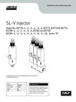
Model No. 85770-1, -2, -3, -4, -5, -6 85771, 85772 85780-1, -2, -3, -4, -5, -6 85781 and 85782 SL-V INJECTOR Series “A”
SINGLE AND MANIFOLD TYPE INJECTORS for dispensing fluid lubricants and greases not exceeding Lincoln ventmeter viscosity of 600 psi. SPECIFICATIONS Minimum operating pressure – 1850 psi [128 bar] Maximum operating pressure – 6000 psi [413 bar] Recommended operating pressure – 2500 psi [172 bar] Maximum vent (recharge) pressure – 1000 psi [69 bar] Temperature Range - -40°F to 180°F [-40°C - 80°C] Lubricant output (adjustable): SL-V - 0.015 to 0.080 cu. in. [0.25 to 1.31 ccm] SL-V HO - 0.015 to 0.305 cu. in. [0.25 to 5.00 ccm] Injectors can be mounted in any position and can be used in circuits with SL-1, SL-11, SL-32 and/or SL33 injectors.
U.S Patent Number 6,705,432 Foreign Patents Pending
One Lincoln Way St. Louis, MO 63120-1578 Phone +1.314.679.4200 Fax +1.800.424.5359
MARCH - 2004
© Copyright 2003 Printed in USA Web site: www.lincolnindustrial.com
- C8 - 301
Section Page
Form 403353
Model No. 85770-1, -2, -3, -4, -5, -6 85771, 85772 85780-1, -2, -3, -4, -5, -6 85781, 85782 SL-V INJECTOR
MANIFOLD TYPE INJECTORS Injector
SL-V
Model
in.
[mm.]
in.
[mm.]
85770-1 Single injector manifold
*
*
2-1/2
[63.5]
85770-2 Tw o injector manifold
*
*
3
[76.2]
85770-3 Three injector manifold
1-1/4
[31.8]
4-1/4
[108]
85770-4 Four injector manifold
2-1/2
[63.5]
5-1/2
[140]
85770-5 Five injector manifold
3-3/4
[95.3]
6-3/4
[171]
85770-6 Six injector manifold
5
[127]
8
85771
SL-V HO
Dimension "A" Dimension "B" Dimension "C"
Type
N/A
Replacement injector
[mm.]
8-3/4
[222]
11-3/16
[284]
[203] N/A
85780-1 Single injector manifold
*
*
2-1/2
[63.5]
85780-2 Tw o injector manifold
*
*
3
[76.2]
85780-3 Three injector manifold
1-1/4
[31.8]
4-1/4
[108]
85780-4 Four injector manifold
2-1/2
[63.5]
5-1/2
[140]
85780-5 Five injector manifold
3-3/4
[95.3]
6-3/4
[171]
85780-6 Six injector manifold
5
[127]
8
85781
in.
N/A
Replacement injector * Single mounting hole
[203] N/A
SINGLE UNIT INJECTORS
Page Number - 2
Injector
Model
SL-V SL-V HO
85772 85782
Type Single unit injector Single unit injector
Dim ension "D" in. [mm.] 7-3/4 [191] 10-3/16 [248]
Form 403353
Model No. 85770-1, -2, -3, -4, -5, -6 85771, 85772 85780-1, -2, -3, -4, -5, -6 85781, 85782 SL-V INJECTOR
12
1
13
2 14
3
15
4
14
5
16
6 7
17
8 9
18
10 19 11
20 Torque to 30-40 In. Lbs.
SERVICE PARTS Item No. 1 2 3 4 5 6 7 8 9 10 11 12 13 14 15 16 17 18 19 20 21
Description
Qty.
23 24
Protective Cap (polycarbonate) O-ring (nitrile) Adjusting Screw Lock Nut Piston Stop Plug O-ring Backup Washer U-cup (polyurethane) O-ring (polyurethane) Piston Assembly O-ring (polyurethane) Fitting Assembly Injector Body O-ring (fluorocarbon) O-ring (fluorocarbon) Spring Spring Spring Seat Body and Plunger Assy. Socket Head Screw (8-32 x 1-1/2) Gasket Single Injector Manifold Tw o Injector Manifold Three Injector Manifold Four Injector Manifold Five Injector Manifold Six Injector Manifold Gasket Adapter Bolt
1 1 1 1 1 1 1 1 1 1 1 1 1 2 1 1 1 1 1 2 1 1 1 1 1 1 1 1 1
25
Adapter
1
22
Part No. SL-V SL-V HO 21 273088 273089 * 272803 272819 11624 273090 273091 25 * Torque to * 40 - 45 Ft. Lbs. 22 * * 23 273092 273093 * 24 90471 Torque to 273094 273095 * 40-45 Ft. Lbs. * MANIFOLD SINGLE UNIT * INJECTORS INJECTOR * 272798 SPECTRUM ADJUSTMENT SLEEVES 273096 272796 Part # Output Ratio from Ratio from Sleeve * in3 (cc) Minim um Output Maxim um Output Color 12658 N/A 0.015 (0.25) 1 0.2 N/A 11962 85785-1 0.03 (0.50) 2 0.4 red 11963 85785-2 0.045 (0.75) 3 0.6 silver 11964 85785-3 0.06 (1.00) 4 0.8 gold 11965 85785-4 0.075 (1.25) 5 1.0 green 246965 NOTE: Remove and discard Lock Nut (Item 4) before installing Spectrum Adjustment * Sleeve onto Adjusting Screw (Item 3). 273097 273098
* Included in 272970 Repair Kit
Form 403353
Page Number - 3
Model No. 85770-1, -2, -3, -4, -5, -6 85771, 85772 85780-1, -2, -3, -4, -5, -6 85781, 85782 SL-V INJECTOR
SL-V Injector Operation Indicator Stem
Stage 1 The injector starts in its normal or rest position. Incoming lubricant is directed through the slide valve to both sides of the piston. The pressure of the incoming lubricant acting on both sides of the piston causes the piston to move downward against the shoulder and fills the measuring chamber. The indicator stem is fully retracted away from the stop of the adjusting screw.
Piston
Springs
Stage 2 Further increase in pressure causes the slide valve to move against the force of the springs. As the slide valve moves, it closes passage 1 and opens passage 2 to the outlet port. The pressure of the incoming lubricant is now acting only upon the bottom of the piston. The incoming lubricant displaces the piston which forces the lubricant in the measuring chamber to be dispensed through passage 2, through the slide valve and through the outlet port to the lube point.
Slide Valve Lubricant Supply
Passage 1 Outlet Port Passage 2 Slide Valve STAGE 2
STAGE 1
Stage 3 The piston will dispense lubricant until the indicator stem hits the stop of the adjusting screw. The volume of lubricant dispensed can be adjusted by limiting the travel of the piston. The piston and slide valve remain in this position until the lubricant pressure in the supply line is vented.
Adjusting Screw Indicator Stem
Stage 4 As the pressure in the supply line vents to 1000 psig [69 bar], the slide valve moves downward and closes passage 2 and opens passage 1. The lubricant pressure in the supply line is now acting upon both sides of the piston causing it to move downward. As the piston moves downward, a volume of lubricant flows from the underside of the piston, past the slide valve, through passage 1 and to the upper side of the piston. Since the volume on top of the piston is greater than the volume under the piston, an additional volume of lubricant flows from the supply line to the upper side of the piston. This volume of lubricant leaving the supply line causes the pressure to drop very quickly. The piston may or may not fully return to the shoulder, depending upon the volume of lubricant in the supply line. The injector is now ready for the next cycle.
Piston
Slide Valve
STAGE 3
Page Number - 4
Passage 1
Passage 2 Lubricant Supply
STAGE 4
Form 403353
Model No. 85770-1, -2, -3, -4, -5, -6 85771, 85772 85780-1, -2, -3, -4, -5, -6 85781, 85782 SL-V INJECTOR
Lincoln Industrial Standard Warranty LIMITED WARRANTY Lincoln warrants the equipment manufactured and supplied by Lincoln to be free from defects in material and workmanship for a period of one (1) year following the date of purchase, excluding therefrom any special, extended, or limited warranty published by Lincoln. If equipment is determined to be defective during this warranty period, it will be repaired or replaced, within Lincoln’s sole discretion, without charge. This warranty is conditioned upon the determination of a Lincoln authorized representative that the equipment is defective. To obtain repair or replacement, you must ship the equipment, transportation charges prepaid, with proof of purchase to a Lincoln Authorized Warranty and Service Center within the warranty period. This warranty is extended to the original retail purchaser only. This warranty does not apply to equipment damaged from accident, overload, abuse, misuse, negligence, faulty installation or abrasive or corrosive material, equipment that has been altered, or equipment repaired by anyone not authorized by Lincoln. This warranty applies only to equipment installed, operated and maintained in strict accordance with the written specifications and recommendations provided by Lincoln or its authorized field personnel. THIS WARRANTY IS EXCLUSIVE AND IS IN LIEU OF ANY OTHER WARRANTIES, EXPRESS OR IMPLIED, INCLUDING, BUT NOT LIMITED TO, THE WARRANTY OF MERCHANTIBILITY OR WARRANTY OF FITNESS FOR A PARTICULAR PURPOSE. In no event shall Lincoln be liable for incidental or consequential damages. Lincoln’s liability for any claim for loss or damages arising out of the sale, resale or use of any Lincoln equipment shall in no event exceed the purchase price. Some jurisdictions do not allow the exclusion or limitation of incidental or consequential damages, therefore the above limitation or exclusion may not apply to you. This warranty gives you specific legal rights. You may also have other rights that vary by jurisdiction. Customers not located in the Western Hemisphere or East Asia: Please contact Lincoln GmbH & Co. KG, Walldorf, Germany, for your warranty rights.
Lincoln Industrial Special Limited Warranty SPECIAL LIMITED 2 YEAR WARRANTY SL-V Series, Single Injectors-85772, 85782, and Replacement Injectors-85771, 85781 Lincoln warrants the SL-V Injector series to be free from defects in material and workmanship for two (2) years following the date of purchase. If an injector model (single or replacement) is determined to be defective by Lincoln, in its sole discretion, during this warranty period, it will be repaired or replaced, at Lincoln’s discretion, without charge.
Lincoln Industrial Contact Information To find Lincoln Industrial’s Nearest Service Center Call one of the following numbers, you may also use our wbsite Customer Service - 314-679-4200 Website - www.lincolnindustrial.com
Form 403353
Page Number - 5
Model No. 85770-1, -2, -3, -4, -5, -6 85771, 85772 85780-1, -2, -3, -4, -5, -6 85781, 85782 SL-V INJECTOR
Declaration by the manufacturer as defined by machinery directive 89/392/EEC Annex IIB Herewith we declare that the supplied model of SL-V is intended to be incorporated into machinery covered by this directive and must not be put into service until the machinery into which it is to be incorporated has been declared in conformity with the provisions of the directive. Applied harmonized standards in particular: EN292 T1/T2 prEN 809
Paul Conley, Chief Engineer
Page Number - 6
Form 403353