![Komatsu Performance Handbook Edition25 [PDF]](https://pdfs.asia/img/200x200/komatsu-performance-handbook-edition25.jpg)
9 0 34 MB
AH_25.book Page 1 Tuesday, March 23, 2004 9:41 AM
SPECIFICATIONS & APPLICATION HANDBOOK Edition 25
March 2004
CONTENTS INDEX
Please note that the performance information included in this book is for estimation purposes only. It is based on information that Komatsu Ltd. has but actual figures will vary with the operating conditions, including material characteristics, site conditions, operator efficiency, etc. Neither Komatsu Ltd. nor its dealers will guarantee that the machines will perform as estimated. Materials and specifications are subject to change without notice.
c 2004 Komatsu All Rights Reserved Printed in Japan
G-1
AH_25.book Page 2 Tuesday, March 23, 2004 9:41 AM
G-2
AH_25.book Page 3 Tuesday, March 23, 2004 9:41 AM
CONTENTS
GENERAL
INDEX
INFORMATION BY INDEX TABLE PREFACE KOMATSU PRODUCT LINE
1 CRAWLER TYPE TRACTORS 1A CRAWLER TYPE TRACTORS 1B BULLDOZERS 1C RIPPERS
1D TOWING WINCHES 1E PIPELAYERS 1F TRIMMING DOZERS
2 EXCAVATORS
2A 2B 2C 2D 2E
2F WHEEL-TYPE EXCAVATORS 2G DEMOLITION 2H RAILWAY MAINTENANCE MACHINES 2J OTHERS
3 WHEEL LOADERS
3A WHEEL LOADERS 3B REACH LOADERS 3C WHEEL DOZERS
3D TRASH COMPACTORS & TRASH LOADERS 3E TOWING TRACTORS
4 OFF-HIGHWAY DUMP TRUCKS
4A OFF-HIGHWAY DUMP TRUCKS 4B ARTICULATED DUMP TRUCKS
4C CRAWLER CARRIERS 4D SLAG DUMP TRUCKS
5 ROAD MAINTENANCE EQUIPMENT
5A MOTOR GRADERS 5B VIBRATORY ROLLERS 5C TIRE ROLLERS
5D OTHER ROAD MAINTENANCE EQUIPMENT
6 BACKHOE LOADERS
6
BACKHOE LOADERS
7 SKID STEER LOADERS
7
SKID STEER LOADERS
8 MOBILE CRUSHERS & RECYCLERS
8A MOBILE CRUSHERS & RECYCLERS
9 MOBILE CRANES
9A ROUGH TERRAIN CRANES 9B REACH TOWER CRANES
EXCAVATORS (BACKHOE) MINIMAL SWING RADIUS EXC. (UU) LIFTING CAPACITY BACKHOE ATTACHMENTS LOADING SHOVELS
10 GENERATOR SETS
10
GENERATOR SETS
11 ENGINES
11
ENGINES
12 TIRES
12
TIRES
13 SPECIAL APPLICATION RECOMMENDATION
13
SPECIAL APPLICATION RECOMMENDATION
14 PRODUCTIVITY
14A PRODUCTIVITY 14B EARTHMOVING DATA
15 OWNING & OPERATING COSTS
15
OWNING & OPERATING COSTS
16 UNIT CONVERSION TABLES 16 UNIT CONVERSION TABLES INDEX
INDEX
More precise index is shown under each section.
G-3
8B MOBILE WOOD TUB GRINDERS 8C MOBILE SOIL RECYCLERS
AH_25.book Page 4 Tuesday, March 23, 2004 9:41 AM
Information Index Table
GENERAL
From here go to appropriate sub-section index page Major products Wheel Dump Loader Truck 3A-2 4A-2 — — 3A-8 4A-5 3A-17 4A-8 3A-17 — 3A-94 4A-11 — — 3A-111 — 3A-144 4A-39
Product Sections Crawler Area of Information Tractor Features (description) 1A-2 Series Selection — Specifications 1A-7 Dimensions (shipping etc.) 1A-7, 1B-5 Working Range — Travel Performance 1A-13 Component Dimensions — Bucket (and Arm) Selection — Undercarriage-Shoes/Tires 1A-16 Ground Pressure 1A-16 Spec. Definitions — 1B (Bulldozer) Attachments 1C (Ripper) 1D (Winch) Loader-truck Combination — 1B-16 (Bulldozer) Production 1C-11 (Ripper) Lifting Capacity —
Related Products (by model designation)
Hydraulic Excavator 2A-2 2A-11 2A-12 2A-27 2A-37 — 2A-45 2A-74 2A-60 2A-64 2A-71
3A-101
2D
Backhoe Loader 6-2
Skid Steer Loader 7-2
6-3 6-4
7-3 7-4
Generator
Engine
— 10-2 — — 10-3 — — — — — —
— 11-2 — — 11-3 — — — — — —
— — — — 9A-10
— — — — —
— — — — —
9B (LT: Reach Tower Crane)
—
—
— — —
— — —
— — —
— 4A-35
3A-131 (Log att.)
— 2A-100 (Backhoe) 2E-19 (L/Shovel) 2C, 2F
3A-147
1E (Pipelayer)
2E (L/Shovel)
3B (WR)
1F (Triming)
2F (PW)
3C (WD)
2B (UU)
3D (WF)
—
3A-151
—
— 4B (HM) (HM: Articulated Dump Truck) 4C (CD) (CD: Crawler Carrier) 4D (HS) (HS: Slag Dump Truck)
3E (WT) Product Sections Area of Information Benefits Features (description) Series Selection Model and Application Specifications Dimensions (shipping etc.) Working Range Travel Performance Component Dimensions Bucket (and Arm) Selection Undercarriage-Shoes/Tires Ground Pressure Spec. Definitions Attachments Loader-truck Combination Production Lifting Capacity
Motor Grader 5A-2 — 5A-4 5A-6 — — — — 5A-15 — 5A-8, 5A-16 — —
Roller — 5B-2 — — 5B-3 5B-5 — — — — — — — — — —
—
5C (JW: Tire Roller)
— — —
— — —
Related Products (by model designation)
Major products Mobile Rough Terrain Crusher Crane 8A-2 — 8A-3 9A-2 — — 8A-5 — 8A-6 9A-6 8A-7 9A-9 — 9A-21 — — — — — — — — — — — — — 8B (BR: Mobile Wood Tub Grinder) 8C (BM: Mobile Soil Recycler) — — —
Only the first page of each section is shown in above table.
G-4
AH_25.book Page 5 Tuesday, March 23, 2004 9:41 AM
Information Index Table
GENERAL
From here go to appropriate sub-section index page Product Sections Area of Information Benefits Features Model Selection Model and Application Specifications Dimensions Working Range Undercarriage-Shoes/Tires Ground Pressure Standard Equipment Attachment Production
Demolition
Road Maintenance
— — 2G-2 — — — —
— — — — — — —
—
—
— 2G-4
— —
—
—
— — Related Products (by model designation) — — Construction Methods Earthmoving Data Cost Calculations Conversion Charts Recomendation
2G-3 — — — —
5D-5 (GS: Wheel Stabilizer) 5D-6 (CS: Crawler Stabilizer) 5D-8 (GC: Road Cutter) 5D-9 (CS: Stone Crusher) 5D-2 — — — —
Application Information Special Railway Application Productivity O & O Costs Maintenance Recomendation — — — — — 1F-3 2H-2 — — — 1F-3 — — — — — — — — — 1F-7 2H-3 — — — — 2H-4 — — — — 2H-5 — — — 15-15 1F-6 — — — Tire Life — 1F-5 — — — — — — — — — 14A — — — Calc. — Method
Trimming Dozer
—
—
—
—
—
—
—
—
—
—
—
—
—
—
—
—
—
—
—
—
1F-2 — — — —
— — — — —
— — — — 13-2
— 14B — — —
— 15 — —
Only the first page of each section is shown in above table.
G-5
AH_25.book Page 6 Tuesday, March 23, 2004 9:41 AM
Preface
GENERAL
PREFACE This handbook referes to machine specifications, productivity and owning & operation cost for construction equipment sold by Komatsu. It serves as a guide for the following cases: * Estimation of productivity for each machine * Estimation of owning & operating costs for each machine * Selection of machines for purchasing construction equipment * Selection of machines for performing construction job The performance of a machine is determined by its production and operating costs. Important machine factors that influence production includes the horsepower, operating weight, capacity of work equipment, traveling speed and types of mechanical, hydraulic and electrical systems. They are referred to in the related section in the handbook. Some of the significant elements that comprise the operating cost factors are the consumption of fuel and lubricants, the service life of tires and undercarriage and the repair cost of components. These expenditures are discussed in the section entitled Owning & Operating Costs. The data and tables in the handbook are based on Komatsu's bench and field tests, computer analysis and many years of experience. We continuously conduct tests to improve the reliability of the data. However, because of the complexity of factors influencing production costs and the deviations that may occur during the preparation of data, Komatsu does not guarantee that the data is exact and that the performance shown in the handbook is always obtainable with the given job conditions. The basic performance data in the handbook are the values when machines are used at ideal efficiency. As performance varies with operator's skill, ground and weather conditions, etc., in reality, the basic data needs to be modified by using the various factors included in the handbook, resulting in different figures depending on the selection of these factors. Owning and operating cost also varies depending upon the machine usage, and the calculation result differs by what job condition and factors are applied for the calculation. Therefore, it should be understood that the calculated figures do not always completely match the actual measured data. Nevertheless, handbook users will be able to make proper approximate calculations based on the data given in the handbook, their work experience and knowledge of local conditions. This handbook is revised yearly. The data in the handbook is accurate at the time of printing; however, Komatsu may make changes in the specifications and materials without notice. Changes are made because of Komatsu's fundamental program of conducting continuous improvements on its products. Therefore, when you need the most updated information or specifications, obtain the latest catalogs through your distributor. This handbook contains machine models produced in the various areas in the world. Specifications may vary depending upon production location; all models are not always available everywhere in the world. The final objective for an owner of construction equipment is to perform the necessary construction job with the best efficiency and safety. It is desirable for an owner to understand the job efficiency factors and the machine use factors before utilizing this handbook. They are as follows: 1. Job efficiency factors 1) Skill of operator In order to obtain high productivity, the skill of the operator needs to match the performance of the machine. It is essential that the operator has the knowledge and skill to obtain high productivity from the machine. Therefore, operators should be given education and training about machine operation, construction job operations and safety. The operator must read and understand the operator's manual. The operator must also read and understand the safety manual of the applicable manufacturers association in each area (AEM in USA, CECE in Europe, etc). The employer should assess the skill of each operator and assign the operator to an appropriate job. The operator should be given clear job instruction.
G-6
AH_25.book Page 7 Tuesday, March 23, 2004 9:41 AM
Preface
GENERAL
2) Selection of type of machine and specification The contractor should select the kind, size and specification of machine that can obtain the optimum job efficiency. The contractor can use his past results and experience to select the most appropriate machine. If the contractor is uncertain about the proper machine selection, it is recommended that the contractor consult with the Komatsu distributor or the Komatsu application engineer. They have abundant information and experience and can provide valuable assistance in machine selection. 3) Selection of construction method To attain the job objective, the contractor must select the proper method of construction or process. The contractor can choose the optimal method of construction and the optimal process by past actual result or experience. If the contractor is uncertain about the selection, it is recommended that the contractor consult a Komatsu application engineer. Komatsu has a program called OFR (Optimum Fleet Recommendation), whitch provides suitable recommendations for optimal method of construction and process. 4) Choice and use of attachments and optional parts Care should be taken in the selection of attachments or optional parts since they affect work efficiency and safety. Typical attachments and optional parts are shown in this handbook. Komatsu has additional attachments and optional parts. You can consult with the distributor, salesman, or Komatsu application engineer for additional details. 5) Use of special application machine This handbook includes relatively popular special application machines (modified machine for special application), but does not include every special application machine because of the limited number of pages. Komatsu will evaluate individual special application work which is not shown in this handbook and may create a special application machine to meet job requirements. You can consult with the distributor, salesman, or application engineer of Komatsu. 2. Machine use factors 1) Operator's protection from hazard The employer has a duty to secure the safety of operators. They must not start work until they understand the machines to be used, method of construction and job site, and until they check and confirm that the operator is protected from all potential hazards. • If an additional protection device is needed on the machine for operator protection, the Komatsu distributor should be consulted. • The owner of a machine for the purpose of raising productivity and durability may want to modify a machine. In such a case, any modifications and attachment installations that may endanger the operator must not be carried out. For example, modifications that hinder an operator's field of view, hinder operation of a machine, hinder access to a machine or worsen the function of brake, steering and ROPS, stability of a machine, etc., must not be performed. 2) Protection from breakdown or lessening of machine life In order to lower O&O cost, it is important to lengthen the economical life of a machine while reducing machine failure. Therefore, the owner of a machine needs to address the following items: • Understand the method of construction and the condition of job site, and choose the type, size, and specification of machine that has ample strength for the job. Komatsu machines are equipped with the adequate strength and structure for typical work. However, when the machine is used in special applications, special strengthening and/or the addition of protection structures may be needed. In such a case, it is recommended that Komatsu should be consulted through the distributor. If the owner of the machine makes modification himself without consulting Komatsu, there are risks of generating problems in the performance, durability and safety of the machine. • To increase production or durability, the owner of a machine may want to convert a main part of the machine or attachments himself, or may want to put attachments other than a Komatsu design which is procured locally, even if it is not a special application. In such a case, it is recommended that Komatsu be consulted through the distributor. Komatsu will propose through the distributor the proper means to respond to the request of a customer. If the owner of the machine makes modification himself without consulting Komatsu, there are risks of generating problems in the performance, durability and safety of the machine.
G-7
AH_25.book Page 8 Tuesday, March 23, 2004 9:41 AM
Preface
GENERAL
3) Prevention of fire The owner and operator of a construction machine must follow the machine's maintenance guidelines and manage the job so that danger of fire will be minimized. A fire breaks out mainly by leakage of fuel, oil and grease; by electrical shorts caused from fatigue, loosening, or rubbing of electric parts and by ignition from engine high temperature parts contacting combustibles, such as plants and papers. • The owner of a machine needs to maintain a machine by daily checks so that the causes described above do not exist. • The operator must confirm by walk-around check before starting the machine that the abovementioned hazards do not exist. If any problems are found, the machine must not be started until the problems are fixed. • Equip a machine with a fire extinguisher in preparation for emergency. 4) Consideration of safety around the machine and environment. Exercise care regarding safety, vibration, noise and flying debris (soil and stone) for the people who work around machines and for the surrounding area before putting a machine into a job site. • Due to carelessness, the people working around the machine may suffer injury when the machine reverses, turns, and the attachment moves, etc. In order to prevent injuries, Komatsu can offer hazard alarm equipment and hazard detection equipment on its machines and the clothing of people working around the machine. The owner of the machine should evaluate whether the equipment on the machine are enough to cover the job site condition and should equip the machine and the people with additional equipment if needed. • Komatsu sells machines that conform to the surrounding noise level regulation in the area sold. However, when it is necessary to have lower noise than a regulation level of the area, it is possible to reduce noise levels by modifying the machine. You are requested to consult Komatsu through its distributor. • It is quite difficult to prevent the vibration of the land and flying debris by modification of the machine. Such problems should be solved by changing the work condition. 5) Compliance with regulations Regulations pertaining to safety, noise, engine exhaust gas, etc. vary in different areas of the world. The owner of a machine has to recognize the regulations about the safety and environment legislated by each country and local government against construction machines, and has to use machines that conform to the applicable regulations. Although Komatsu supplies machines that conform to each regulation in the world, it is necessary to confirm through the Komatsu distributor if the machine conforms to all regulations in that area, before putting the machine to work. Occasionally, a machine manufactured for another area in the world may be moved and relocated without Komatsu's knowledge. In this case, the machine may not have the specifications or structure to satisfy regulations of the area where the machine is located. In such a case, check in advance to determine if it conforms to the regulation of the area. If it does not conform, the owner must either make the necessary modifications to the machine to make it conform, or not operate the machine there. 6) Appropriate maintenance and management of a machine The most important factor to maximize machine operation is performing maintenance and management of the machine correctly. It is essential to perform daily check & maintenance and periodic inspection & maintenance procedures shown in the operation manual of each machine.
G-8
AH_25.book Page 9 Tuesday, March 23, 2004 9:41 AM
The Komatsu Product Line
GENERAL
BULLDOZERS Flywheel horsepower 40 to 1150 HP (29.5 to 858 kW)
D575A-3 SD
D275A-5 D275AX-5
D70LE-8
D575A-3
D155A-2A
D68ESS-12
D65E-12 D65EX-15
D475A-5 SD
D155A-5 D155AX-5
D475A-5
D85EX-15
D61EX-12
D41E-6
D85ESS-2
D375A-5
D85ESS-2A
D39EX-21 D37EX-21 D31EX-21 D21A-8
SWAMP BULLDOZERS Flywheel horsepower 40 to 225 HP (29.5 to 168 kW)
D85PX-15
D65P-12 D65PX-15
D61PX-12
D41P-6
D39PX-21 D37PX-21 D31PX-21 D21P-8
PIPELAYERS Flywheel horsepower 225 to 360 HP (168 to 259 kW)
D355C-3
D155C-1
D85C-21
G-9
AH_25.book Page 10 Tuesday, March 23, 2004 9:41 AM
The Komatsu Product Line
GENERAL
HYDRAULIC EXCAVATORS (Back hoe) Operating weight 380 to approx. 710,000 kg (840 to approx. 1,565,270 lb)
PC8000-6
PC5500-6
PC1800-6
PC1250-7 PC1250LC-7 PC1250SP-7
PC450-7 PC450LC-7
PC290LC-7 PC290NLC-7
PC180LC-7
PC40MR-2 PC50MR-2
PC308USLC-3
PC4000-6
PC800-7 PC800SE-7
PC400-7 PC400LC-7 PC400SE-7
PC160LC-7
PC240LC-7 PC240NLC-7
PC130-6
PC45R-8
PC35R-8
PC228US-3 PC228USLC-3
PC350-7 PC350LC-7 PC360-7
PC230NHD-7
PC120-6 PC120LC-6
PC35MR-2 PC30MR-2 PC27MRX
PC138US-2 PC138USLC-2
PC1400
PC750-7 PC750LC-7 PC750SE-7
PC380-7
PC270LC-7
PC3000
PC20R-8 PC27R-8
PC300-7 PC300SE-7 PC300LC-7 PC300HD-7
PC340LC-7 PC340NLC-7
PC220-7 PC220LC-7
PC110R-1
PC600-7 PC600LC-7
PC210-7 PC210LC-7 PC210NLC-7
PC100F-6
PC15MRX PC20MRX
PC200-7 PC200LC-7
PC75R-2 PC95R-2
PC12R-8 PC15R-8
PC09-1
PC01-1
PC78US-6 PC78MR-6
MSRX (Minimal swing radius excavator) Operating weight 5,290 to 13,580 kg (11,670 to 29,940 lb)
PC128UU-2
PC78UU-6
PC58UU-3
HYDRAULIC EXCAVATORS (Loading shovel) Operating weight 43,100 to approx. 700,000 kg (95,020 to approx. 1,543,200 lb)
PC8000-6
PC1800-6
PC5500-6
PC1250-7
PC750-7
PC4000-6
PC3000
PC600-7 PC600LC-7
PC1400
PC400-7 PC400LC-7
HYDRAULIC EXCAVATORS (Wheel type) Operating weight 7,500 to 21,650 kg (16,530 to 47,730 lb)
PW220-7
PW210-1
PW200-7
PW170ES-6
G-10
PW150ES-6
PW130ES-6
PW110R-1
PW100-3
PW75R-2 PW95R-2
AH_25.book Page 11 Tuesday, March 23, 2004 9:41 AM
The Komatsu Product Line
GENERAL
WHEEL LOADERS Bucket capacity 0.3 to 20 m3 (0.4 to 26.2 yd3) (C) indicates custom series.
WA1200-3
WA900-3
WA500-3
WA200-5
WA480-5
WA200PT-5
WA800-3
WA450-5 WA470-5 WA470-3
WA150-5
WA115-3
WA400-5 WA430-5
WA95-3 WA90-3
WA700-3
WA380-3 WA380-5
WA420-3
WA80-3
WA85-3 WA75-3
WA65-3
WA600-3
WA320-3 (C) WA320-5
WA50-3
WA250-5 WA270-5
WA250PT-5
WA30-5
WHEEL DOZERS
REACH LOADERS
Flywheel horsepower 454 to 853 HP (338 to 853 kW)
Bucket capacity 0.8 to 1.0 m3 (1.05 to 1.3 yd3)
WD900-3
WD600-3
WD500-3
WR11-3
WD420-3
WR8-1
TRASH LOADERS
TRASH COMPACTORS
Bucket capacity 3.0 to 4.7 m3 (3.9 to 6.1 yd3)
Operating weight 24,600 to 45,500 kg (54,230 to 100,310 lb)
WF550-3
WF450-3
TOWING TRACTORS
Operating weight 25,000 to 50,000 kg (55,120 to 110,230 lb)
WT500E
WF650T-3
WF350-3
WT250E
WF550T-3
WF450T-3
SKID STEER LOADERS Bucket capacity 0.16 to 0.45 m3 (0.21 to 0.59 yd3)
SK1026-5
SK1020-5
SK820-5
SK818-5
SK815-5
SK714-5
SK510-5
BACKHOE LOADERS Bucket capacity 0.7 to 1.03 m3 (0.92 to 1.35 yd3)
WB150-2 WB150PS-2
WB140-2 WB140PS-2
WB98A-2
WB97S-2 WB97R-2
WB93R-2
WB91R-2
WB70A-1
OFF-HIGHWAY DUMP TRUCKS Hauling capacity 25 to 290 ton (28 to 320 US ton)
930E-3
HD1500-5
HD405-6
830E
HD1200-1
HD325-6 HD325-6 4WD
730E
HD985-5
HD785-5
HD255-5
G-11
630E
HD605-7
HD465-7
SK04J-2
AH_25.book Page 12 Tuesday, March 23, 2004 9:41 AM
The Komatsu Product Line
GENERAL
SLAG DUMP TRUCKS
ARTICULATED DUMP TRUCKS
Pot capacity 4 to 15 m3 (5.2 to 19.6 yd3)
Hauling capacity 50 to 67 ton (55 to 68.5 US ton)
HS600S-3
HS150S-11
HM400-1
HS100S-11
HM350-1
HM300-1
CRAWLER CARRIERS Hauling capacity 6 to 11 ton (6.6 to 12.1 US ton)
CD110R-2
CD60R-1
MOTOR GRADERS Flywheel horsepower 125 to 280 HP (93 to 209 kW)
GD825A-2
GD555-3A GD555-3C
GD705A-4
GD511A-1
GD675-3A GD675-3C
GD661A-1
GD655-3A GD655-3C
GD611A-1
GD510R-1
ROAD STABILIZERS Flywheel horsepower 203 to 355 HP (152 to 265 kW)
GS360-2
CS360-2
CS210-2
ROAD CUTTER
STONE CRUSHER
Flywheel horsepower 375 HP (280 kW)
Flywheel horsepower 230 HP (152 kW)
GC380F-2
CS210-2
VIBRATORY ROLLERS Operating weight 600 to 11,250 kg (1,320 to 24,800 lb)
JV100A-2 JV100WA-2 JV100WP-2
JV40CW-5
JV40DW-5
JV25CW-3
TIRE ROLLER Operating weight 3,000 kg (6,610 lb)
JW30-2
G-12
JV25DW-3
JV08H-3
JV06H-3
AH_25.book Page 13 Tuesday, March 23, 2004 9:41 AM
The Komatsu Products Line
GENERAL
ROUGH TERRAIN CRANES
REACH TOWER CRANES
Maximum rated load 10 to 50 ton (11 to 55 US ton)
Maximum rated load 4.9 to 6.9 ton (5.4 to 6.6 US ton)
LW500-1
LW250-5
LW100-1
LT500-1
MOBILE CRUSHER & RECYCLERS
LT300-2
Flywheel horsepower 54.2 to 612 HP (40 to 456 kW)
BR550JG-1
BR380JG-1
BR210JG-1
BR250RG-1
BR480RG-1
BZ210-1
BR100JG-2
BR100RG-1
BR200T-1
BR200S-1
BR300S-1
BR120T-1
RAILWAY MAINTENANCE MACHINES Operating weight 6,800 to 10,635 kg (14,990 to 23,450 lb)
PC78UUT-6
PC58UUT-3
DIESEL GENERATOR SETS Rated output 41 to 1,000 kVA (33 to 800 kW)
EGS1200BS-6 EGS1200B-6 EGS1200-6
EGS1050BS-6 EGS1050B-6 EGS1050-6
EGS1000BS-6 EGS1000B-6 EGS1000-6
EGS850BS-6 EGS850B-6 EGS850-6
EGS760BS-6 EGS760B-6 EGS760-6
EGS650BS-6 EGS650B-6 EGS650-6
EGS630BS-6 EGS630B-6 EGS630-6
EGS570BS-6 EGS570B-6 EGS570-6
EGS500BS-6 EGS500B-6 EGS500-6
EGS380BS-6 EGS380B-6 EGS380-6
EGS360BS-6 EGS360B-6 EGS360-6
EGS300BS-6 EGS300B-6 EGS300-6
EGS240BS-6 EGS240B-6 EGS240-6
EGS190BS-6 EGS190B-6 EGS190-6
EGS160BS-6 EGS160B-6 EGS160-6
EGS120BS-6 EGS120B-6 EGS120-6
EGS90BS-5 EGS90B-5 EGS90-5
EGS65BS-5 EGS65B-5 EGS65-5
EGS45BS-5 EGS45B-5 EGS45-5
G-13
AH_25.book Page 14 Tuesday, March 23, 2004 9:41 AM
The Komatsu Products Line
GENERAL
ENGINES Piston displacement 3.92 to 61.8 Itr (239 to 3771 cu in)
SA12V170E
S6D108E SA6D108E SAA6D108E
SA12V140 SDA12V140
6D102E S6D102E SA6D102E SAA6D102E
SA6D170E SAA6D170E
4D102E S4D102E SA4D102E SAA4D102E
S6D140E SA6D140E SAA6D140E
SAA6D95LE
G-14
6D125E S6D125E SA6D125E SAA6D125E
4D95LE S4D95LE
S6D114E SA6D114E SAA6D114E
CONTENTS
SECTION
1
INDEX
CRAWLER-TYPE TRACTORS Sec 1A BULLDOZERS Sec 1B RIPPERS Sec 1C TOWING WINCHES Sec 1D PIPELAYERS Sec 1E TRIMMING DOZERS Sec 1F
AH_25.book Page 1 Tuesday, March 23, 2004 9:41 AM
SECTION
1A
CRAWLER-TYPE TRACTORS CONTENTS Features .................................................................... 1A-2 Specifications ........................................................... 1A-7 Specifications (Low ground pressure) ................. 1A-11 Drawbar pull vs. travel speed ............................... 1A-13 Ground pressure .................................................... 1A-16 Shoe application .................................................... 1A-18 Shoe selection ........................................................ 1A-19 Roller guard installation ........................................ 1A-21 Upper attachment ................................................... 1A-23
1A-1
AH_25.book Page 2 Tuesday, March 23, 2004 9:41 AM
Features
CRAWLER-TYPE TRACTORS
High productivity The high-power engine, highly efficient power train, large drawbar pull provided by the conventional undercarriage, and the high performance work equipment provide high productivity.
• Large capacity blade Large capacity blade, powerful digging force, large up-and-down movement of the blade, and high strength provided by high tensile steel.
• Uniquely designed ripper
FVBH0305
The unique linkage design enables the ripper point to draw an ideal locus during cylinder tilting for effective excavation of embedded rocks.
• Automatic lock-up torque converter When the lock-up clutch is engaged, the pump and the turbine are virtually connected and the internal power loss of the torque converter is minimized. (D275AX, D375A and D475A)
Torque converter
Engine
• Resilient Equalized Undercarriage (REU) This highly advanced undercarriage system utilizes an X-shape bogie structure with an independent see-saw movement for the track rollers. This allows the shoes to always follow the contour of the ground for excellent traction. The bogies contact the track frame through rubber shock absorber reduces vibration and shock. (D155A-5, D155AX and D575A)
Dependable and high-performance
•
•
•
• •
Idler
Sprocket
FZD00685
• Komatsu's diesel engine delivers a strong
•
FKD00444
X-bogie system
components
•
Transmission
horsepower and has a direct-injection system for fuel savings and cleaner exhaust. The TORQFLOW transmission not only ensures smooth and responsive power shifting, but also makes instant speed and directional changes by a single lever. The HYDROSHIFT transmission ensures not only efficient power transmitting ability for reduced fuel costs, but also a single-lever speed control and F/ R directional changes for easy operation. (D21, D31-20, D37-5 and D41) Wet, multiple-disc type steering clutches and brakes ensure long service life and eliminate troublesome brake-lining adjustments. (D41, D65, D155A-5, D275A, D375A, D475A and D575A) Double reduction final drives feature a large reduction ratio and minimize shocks to the power train components and extend the life of components. [Except D21, D31-20, D37-5 and D41] Lubricated track links: Since the clearance between the link pin and bushing is lubricated, wear and pitch extensions are minimized for extended service life. Unique dust seals prevent dust from entering into pin-to-bushing clearance for extended service. Floating seals in the idlers and rollers keep dirt out and lubricant in for durable operation.
1A-2
AH_25.book Page 3 Tuesday, March 23, 2004 9:41 AM
Features • Reduction of man-hours for turning over the
bushings by employment of wedge ring. (Large Class) • Strengthening of undercarriage by increase of press fitting width of pin. (Small-middle Class) The most important matters for the undercarriage of a bulldozer are holding of the oil filled in the links and easiness of turning over the bushings. KOMATSU increased the rigidity and abrasion life of the links and lowered the press fitting force of the pins to reduce scuffing when the links are disassembled. As a result, the bushings are turned over extremely easily. It's the link, the repair cost of the undercarriage of a bulldozer is the highest of all. You can reduce the repair cost with the turning over the bushings drastically.
CRAWLER-TYPE TRACTORS NEW
CURRENT
Track roller Track link
Roller guard Wedge ring
WEDGE RING
CURRENT
NEW
Track link Dust seal Link pin Bushing WIDE
NARROW
PRESS FITTING WIDTH Repair cost of the undercarriage Others
Use Others Turning over the bushings
Track 2
Track 2
Track 1
Track 1
With turning over the bushings
Without turning over the bushings
Before turning over the bushings
Tu
rn
in
g
ov
er
New bushings
Track 3
Use After turning over the bushings
Used bushings
• Modular design
Power train unit
The sealed, modular design allows the powertrain components to be mounted / dismounted without any oil spillage, making servicing work clean, smooth and easy. (D41, D61, D65, D155A-5, D155AX, D275, D375A, D475A and D575A)
Engine
Final drive FVDM0692
1A-3
AH_25.book Page 4 Tuesday, March 23, 2004 9:41 AM
Features
CRAWLER-TYPE TRACTORS
Easy operation / Operator comfort • Operator-oriented arrangement of control levers, pedals, instruments and operator seat.
• Walk-through operator compartment provides • • •
•
easy boarding and exiting. Operator seat can be adjusted to provide the most suitable operating posture. Steering clutches and brakes are interconnected for easy operation. Low profile design assures excellent machine balance and a low center of gravity, making machine dynamically stable and controllable, accounting for operator confidence and comfort. Oscillating type equalizer bar suspension absorbs vibrations and shocks for high mobility and comfortable ride even on rugged terrain. [Except D21, D31/D37/D39 and D41]
FLD00456
• Wrist-control-type single lever for steering/directional and speed change
FZDM0699
All speed and directional changes, 1st to 3rd forward and reverse, and right-and left-hand steering are controlled with just a joystick singlelever on the left. (D21, D41, D61, D65, D155A-5/ D155AX and D475A )
Steering/speed/direction control lever
Blade control le
Forward/reverse
Raise
• Blade control joystick Blade lift, angle and tilt operations are instantly accomplished with a joystick right single-lever. The introduction of this left and right "joystick" system permits simultaneous traveling and working, offering both ease and a shorter cycle time. (D21, D31-20, D37-5, D41 and D61)
Tilt
Steering
Angl
Speed Right sprocket
• Hydrostatic steering system (HSS) Engine power is ideally distributed to the left and right tracks in portion to lever movement each time the machine makes a turn; the outside track moves faster and the inside slower, providing a smooth and powerful turn. (D61, D65EX/PX, D155AX and D275AX)
Left sprocket
• Palm Command Control System Palm Command Control System (PCCS) joystick controls for all directional movements. Pushing the joystick forward results in forward machine travel, while pulling it rearward reverses the machine. Simply tilt the joystick to the left to make a left turn. Tilt it to the right for a right turn. The travel speed is selected by pressing the shift button on the palm lever. (D31/D37/D39-21, D275, D375A and D575A SD)
1A-4
PCCS travel control lever
PCCS blade control lever
Forward and reverse
Lifting and lowering
Right and left steering
Tilting
First, to second, to third shifting
Left and right angling FVBH0229
AH_25.book Page 5 Tuesday, March 23, 2004 9:41 AM
Features
CRAWLER-TYPE TRACTORS
• Centralized oil pressure inspection ports
D375A-5
Oil pressure check ports are centralized on the left side of the chassis to make it easier to carry out inspection and maintenance.
Single tilt Dual tilt
• Palm Command PPC Controlled Blade Control Joystick
TI LT
SIN
GL
DUA
L
E
Blade control joystick uses the PPC (Proportional Pressure Control) valve and palm command joystick the same as travel control joystick. PPC control uses the highly reliable Komatsu hydraulic system enabling superb fine control. (Dual tilt and pitch operation are enabled by depressing switch with a thumb. This is available when optional dual tilt dozer is installed.) (D275-5, D375A and D575A-3 SD)
PITCH
3
4
FVDM0808A
Easy maintenance • Bolt-on type sprocket or segmented sprocket
teeth for easy in- field replacement. [Except D21] • Simple maintenance is promoted through adoption of spin-on type fuel and full-flow filters, an air cleaner with an automatic dust evacuator, and others.
FLD00421
• Maintenance-free, wet, multiple-disc brakes To ensure long life and dependability maintenance-free, wet, multiple-disc brakes are utilized. (D41, D61, D65, D155A-5/D155AX, D275A, D375A, D475A and D575A)
KomStat Hydrostatic Transmission
Track Eng
• 3-speed HST The D31/D37/D39-21 are equipped with Komatsu’s exclusive KomStat Hydrostatic Transmission (HST) consists of dual-path and closed-circuit with two variable displacement piston pumps and two 3-speed variable displacement travel motors. The 3-speed variable capacity travel motors allow the operator to select the optimum speed to match specific jobs.
COUPLING
Front HST pump
PPC
Rear HST pump
Charge pump
Right side HST motor
Left side HST motor Final drive
Final drive Sprocket
• Automatic shift between 1st and 2nd speeds
Parking brake FZDM0847
KomStat shifts automatically between 1st and 2nd speed depending on load or ground conditions to facilitate efficient operation.
• Intermediate speed selection Enables the setting of intermediate speed in each speed range as operator desires or optimum travel speed to match job conditions. This means, for example, intermediate speeds of 1st speed (4.3 km/h 2.7mph), such as 3.0 km/h 1.9 mph etc., are obtained by using the newly developed PPC valve with friction disc clutch. This contributes to increased job efficiency on fine or rough grading operation with optimum travel speed to match job conditions.
1A-5
AH_25.book Page 6 Tuesday, March 23, 2004 9:41 AM
Features • HST dynamic brakes
CRAWLER-TYPE TRACTORS Fulcrum of major bogie
KomStat uses HST dynamic brakes to ensure safe operation. Parking brake is wet, multiple-disc type with a unique drag-prevention control to keep hydraulic oil clean. (D31, D37 and D39)
• K-Bogie undercarriage system New K-Bogie undercarriage system retains prior advantages, with new additional features. New features on K-Bogie Undercarriage System: • K-bogies oscillate with two fulcrums, and track roller vertical travel is greatly increased. Impact loading on all undercarriage components has been reduced and durability of components is improved since track rollers are always in contact with tack link. • Undercarriage life is improved due to better control of track chain alignment with track rollers. • Riding comfort is improved by reducing vibration and shock when traveling over rough terrain. (D275A, D275AX, D375A and D475A)
• Auto-shift down function Controller monitors engine speed, travel gear and travel speed. When load is applied and machine travel speed is reduced, the controller automatically downshifts to optimize gear speed to provide high fuel efficiency. This function provides comfortable operation and high productivity without manual downshifting. (This function can be deactivated with cancel switch). (D275, D375A and D575A SD)
• Preset travel speed selection function Preset travel speed selection function is standard equipment, enabling the operator to select fore and aft travel speed among three preset patterns, F1-R2, F2-R2 and manual shift. When F1-R2 or F2-R2 preset pattern is selected, and travel control joystick moves from forward to reverse direction, the machine travels forward/reverse with F1/R2 or F2/R2 speed automatically. This function reduces gear shifting time during repeated round trip operations. (D275, D375A and D575A SD)
1A-6
Fulcrum of minor bogie
AH_25.book Page 7 Tuesday, March 23, 2004 9:41 AM
Specifications
Item OPERATING WEIGHT* TRACTOR WEIGHT FLYWHEEL HORSEPOWER PERFORMANCE: Travel speed Forward 1st 2nd 3rd Reverse 1st 2nd 3rd Max. drawbar pull DIMENSIONS: Overall length (tractor) Overall length* Overall width (w/o trunnion) Overall width (with blade)* Overall height (tractor)** Overall height* Track gauge Length of track on ground ENGINE: Model No.of cylindersbore × stroke Piston displacement UNDERCARRIAGE: No.of rollers (carrier/track) Width of standard shoe FUEL TANK CAPACITY (Refilled): *) Spec conditions: Bulldozer Rear attachment Upper attachment Item OPERATING WEIGHT* TRACTOR WEIGHT FLYWHEEL HORSEPOWER PERFORMANCE: Travel speed Forward 1st 2nd 3rd Reverse 1st 2nd 3rd Max. drawbar pull DIMENSIONS: Overall length (tractor) Overall length* Overall width (w/o trunnion) Overall width (with blade)* Overall height (tractor)** Overall height* Track gauge Length of track on ground ENGINE: Model No.of cylindersbore × stroke Piston displacement UNDERCARRIAGE: No.of rollers (carrier/track) Width of standard shoe FUEL TANK CAPACITY (Refilled): *) Spec conditions: Bulldozer Rear attachment Upper attachment
Model
CRAWLER-TYPE TRACTORS
D21A-8
D31EX-21
D31EX-21***
D37EX-21
kg (lb) kg (lb) HP (kW)/RPM
3710 (8,180) 3160 (6,970) 40 (29.5)/2450
7130 (15,720) 5775 (12,730) 75 (56)/2000
7130 (15,720) 5775 (12,730) 75 (56)/2000
7410 (16,340) 6010 (13,250) 85 (63)/2000
km/h (MPH)
2.6 (1.6) 4.4 (2.7) — 3.3 (2.1) 5.6 (3.5) — 4520 (9,970/44.3)
3.4 (2.1) 5.6 (3.5) 8.5 (5.3) 4.1 (2.5) 6.5 (4.0) 8.5 (5.3) 12500 (27,560/123)
0.8 (0.5) to 8.5 (5.3) — 0.8 (0.5) to 8.5 (5.3) — 12500 (27,560/123)
3.4 (2.1) 5.6 (3.5) 8.5 (5.3) 4.1 (2.5) 6.5 (4.0) 8.5 (5.3) 12500 (27,560/123)
ltr. (cu.in)
2405 (7'11") 3250 (10'8") 1610 (5'3") 2170 (7'1") 1785 (5'10") 2450 (8') 1310 (4'4") 1685 (5'6") KOMATSU 4D94LE 4-94 × 110 (3.70 × 4.33) 3.053 (186)
3055 (10'0") 4015 (13'2") 1850 (6'1") 2435 (8'0") 1890 (6'2") 2700 (8'10") 1450 (4'9") 2010 (6'7") KOMATSU SAA4D102E 4-102 × 120 (4.02 × 4.72) 3.92 (239)
3055 (10'0") 4015 (13'2") 1850 (6'1") 2435 (8'0") 1890 (6'2") 2700 (8'10") 1450 (4'9") 2010 (6'7") KOMATSU SAA4D102E 4-102 × 120 (4.02 × 4.72) 3.92 (239)
3055 (10'0") 4015 (13'2") 1850 (6'1") 2720 (8'11") 1890 (6'2") 2700 (8'10") 1450 (4'9") 2240 (7'4") KOMATSU SAA4D102E 4-102 × 120 (4.02 × 4.72) 3.92 (239)
mm (in) ltr. (U.S.Gal)
1/5 300 (11.8) 60 (15.9)
1/5 400 (15.7) 165 (43.6)
1/5 400 (15.7) 165 (43.6)
1/6 400 (15.7) 165 (43.6)
PAT — —
PAT — ROPS canopy
PAT — ROPS canopy
PAT — ROPS canopy
kg (lb/kN) mm (ft.in) mm (ft.in) mm (ft.in) mm (ft.in) mm (ft.in) mm (ft.in) mm (ft.in) mm (ft.in) mm (in)
Model
D37EX-21***
D39EX-21
D39EX-21***
D41E-6
kg (lb) kg (lb) HP (kW)/RPM
7410 (16,340) 6010 (13,250) 85 (63)/2000
8520 (18,780) 6950 (15,320) 95 (71)/2200
8520 (18,780) 6950 (15,320) 95 (71)/2200
10950 (24,140) 8790 (19,380) 110 (82)/2300
km/h (MPH)
0.8 (0.5) to 8.5 (5.3) — 0.8 (0.5) to 8.5 (5.3) — 12500 (27,560/123)
3.4 (2.1) 5.6 (3.5) 8.5 (5.3) 4.1 (2.5) 6.5 (4.1) 8.5 (5.3) 13800 (30,420/135)
0.8 (0.5) to 8.5 (5.3) — 0.8 (0.5) to 8.5 (5.3) — 13800 (30,420/135)
2.4 (1.5) 4.4 (2.7) 7.6 (4.7) 3.0 (1.9) 5.5 (3.4) 9.4 (5.8) 14740 (32,500/144.6)
ltr. (cu.in)
3055 (10'0") 4015 (13'2") 1850 (6'1") 2720 (8'11") 1890 (6'2") 2700 (8'10") 1450 (4'9") 2240 (7'4") KOMATSU SAA4D102E 4-102 × 120 (4.02 × 4.72) 3.92 (239)
3195(10'6") 4200 (13'9") 2110 (6'11") 2740 (9'0") 1965 (6'5") 2770 (9'1") 1650 (5'5") 2360 (7'9") KOMATSU SAA4D102E 4-102 × 120 (4.02 × 4.72) 3.92 (239)
3195(10'6") 4200 (13'9") 2110 (6'11") 2740 (9'0") 1965 (6'5") 2770 (9'1") 1650 (5'5") 2360 (7'9") KOMATSU SAA4D102E 4-102 × 120 (4.02 × 4.72) 3.92 (239)
3610 (11'11") 4880 (16'0") 2300 (7'7") 3045 (10'0") 2020 (6'8") 2900 (9'6") 1790 (5'10") 2485 (8'2") KOMATSU SA6D102E 6-102 × 120 (4.02 × 4.72) 5.88 (359)
mm (in) ltr. (U.S.Gal)
1/6 400 (15.7) 165 (43.6)
1/6 460 (18.1) 165 (43.6)
1/6 460 (18.1) 165 (43.6)
1/6 510 (20.1) 250 (66.0)
PAT — ROPS canopy
PAT — ROPS canopy
PAT — ROPS canopy
PAT — ROPS canopy
PAT — ROPS canopy
kg (lb/kN) mm (ft.in) mm (ft.in) mm (ft.in) mm (ft.in) mm (ft.in) mm (ft.in) mm (ft.in) mm (ft.in) mm (in)
** : Without canopy, exhaust pipe, pre-cleaner cap or other easily removed encumbrances. *** : With variable travel speed mode *4 : Long track spec.
1A-7
AH_25.book Page 8 Tuesday, March 23, 2004 9:41 AM
Specifications
Item OPERATING WEIGHT* TRACTOR WEIGHT FLYWHEEL HORSEPOWER PERFORMANCE: Travel speed Forward 1st 2nd 3rd Reverse 1st 2nd 3rd Max. drawbar pull DIMENSIONS: Overall length (tractor) Overall length* Overall width (w/o trunnion) Overall width (with blade)* Overall height (tractor)** Overall height* Track gauge Length of track on ground ENGINE: Model No.of cylindersbore × stroke Piston displacement UNDERCARRIAGE: No.of rollers (carrier/track) Width of standard shoe FUEL TANK CAPACITY (Refilled): *) Spec conditions: Bulldozer Rear attachment Upper attachment Item OPERATING WEIGHT* TRACTOR WEIGHT FLYWHEEL HORSEPOWER PERFORMANCE: Travel speed Forward 1st 2nd 3rd Reverse 1st 2nd 3rd Max. drawbar pull DIMENSIONS: Overall length (tractor) Overall length* Overall width (w/o trunnion) Overall width (with blade)* Overall height (tractor)** Overall height* Track gauge Length of track on ground ENGINE: Model No.of cylindersbore × stroke Piston displacement UNDERCARRIAGE: No.of rollers (carrier/track) Width of standard shoe FUEL TANK CAPACITY (Refilled): *) Spec conditions: Bulldozer Rear attachment Upper attachment
Model
CRAWLER-TYPE TRACTORS
D61EX-12
D61EX-12*4
D65E-12
D65EX-15
kg (lb) kg (lb) HP (kW)/RPM
15800 (34,830) 13130 (28,950) 150 (112)/1800
16500 (36,380) 13830 (30,490) 150 (112)/1800
19125 (42,160) 15620 (34,440) 180 (135)/1950
20080 (44,270) 16350 (36,050) 190 (142)/1950
km/h (MPH)
3.5 (2.2) 6.0 (3.7) 10.3 (6.4) 4.6 (1.9) 7.9 (4.9) 12.8 (8.0) — —
3.5 (2.2) 6.0 (3.7) 10.3 (6.4) 4.6 (1.9) 7.9 (4.9) 12.8 (8.0) — —
3.9 (2.4) 6.8 (4.2) 10.6 (6.6) 5.0 (3.1) 8.6 (5.3) 13.4 (8.3) —
3.9 (2.4) 6.8 (4.2) 10.6 (6.6) 5.0 (3.1) 8.6 (5.3) 13.4 (8.3) —
ltr. (cu.in)
3935 (12'11") 5030 (16'6") 2500 (8'2") 3275 (10'9") 2195 (7'2") 3115 (10'3") 1900 (6'3") 2600 (8'6") KOMATSU SA6D114E 6-114 × 135 (4.49 × 5.31) 8.27 (505)
4160 (13'8") 5440 (17'10") 2500 (8'2") 3275 (10'9") 2195 (7'2") 3115 (10'3") 1900 (6'3") 3170 (10'5") KOMATSU SA6D114E 6-114 × 135 (4.49 × 5.31) 8.27 (505)
4365 (14'4") 5440 (17'10") 2390 (7'10") 3460 (11'4") 2330 (7'8") 3165 (10'5") 1880 (6'2") 2675 (8'9") KOMATSU 6D125E 6 -125 × 150 (4.92 × 5.91) 11.04 (674)
4365 (14'4") 5440 (17'10") 2390 (7'10") 3460 (11'4") 2330 (7'8") 3220 (10'7") 1880 (6'2") 2675 (8'9") KOMATSU SA6D125E 6 -125 × 150 (4.92 × 5.91) 11.04 (674)
mm (in) ltr. (U.S.Gal)
2/6 600 (23.6) 337 (89.0)
2/8 600 (23.6) 337 (89.0)
2/7 510 (20.1) 406 (107)
2/7 510 (20.1) 415 (109.6)
PAT — ROPS canopy
PAT — ROPS canopy
Semi-U tilt — ROPS canopy
Semi-U tilt — Steel cab, ROPS
kg (lb/kN) mm (ft.in) mm (ft.in) mm (ft.in) mm (ft.in) mm (ft.in) mm (ft.in) mm (ft.in) mm (ft.in) mm (in)
Model
D65EX-15*4
D68ESS-12
D70LE-8***
D85ESS-2
kg (lb) kg (lb) HP (kW)/RPM
20820 (45,900) 17090 (37,680) 190 (142)/1950
18800 (41,500) 14280 (31,490) 155 (116)/1850
19970 (44,030) 13850 (30,530) 185 (138)/1850
21490 (47,380) 15620 (34,440) 215 (161)/1950
km/h (MPH)
3.9 (2.4) 6.8 (4.2) 10.6 (6.6) 5.0 (3.1) 8.6 (5.3) 13.4 (8.3) —
3.4 (2.1) 5.8 (3.6) 9.0 (6.0) 4.4 (2.7) 7.6 (4.7) 11.3 (7.0)
2.6 (1.6) 3.2 (2.0) 4.7 (2.9) 3.3 (2.1) 4.2 (2.6) 6.1 (3.8) 19190 (42,310/188)
3.9 (2.4) 6.8 (4.2) 10.6 (6.6) 5.0 (3.1) 8.6 (5.3) 13.4 (8.3) —
ltr. (cu.in)
4365 (14'4") 5845 (19'2") 2390 (7'10") 3460 (11'6") 2330 (7'8") 3220 (10'9") 1880 (6'2") 3285 (10'9") KOMATSU SA6D125E 6 -125 × 150 (4.92 × 5.91) 11.04 (674)
4100 (13'5") 6120 (20'1") 2535 (8'4") 3275 (10'9") 2305 (7'7") 3135 (10'3") 1925 (6'4") 2930 (9'7") KOMATSU S6D114E 4 -114 x 135 (4.49 x 5.31) 8.27 (505)
4075 (13'4") 5230 (17'2") 2490 (8'2") 4100 (13'5") 2385 (7'10") 3020 (9'11") 1880 (6'2") 2635 (8'8") KOMATSU 6D125 6-125 × 150 (4.92 × 5.91) 11.04 (674)
4135 (13'7'') 5930 (19'5") 2660 (8'9'') 4370 (14'4") 2375 (7'10'') 2560 (8'5") 2050 (6'9'') 2980 (9'9'') KOMATSU S6D125 6-125 × 150 (4.92 × 5.91) 11.04 (674)
mm (in) ltr. (U.S.Gal)
2/8 510 (20.1) 415 (109.6)
2/7 610 (24") 315 (93.3)
2/7 610 (24.0) 320 (84.5)
2/8 610 (24.0) 407 (107.5)
Semi-U tilt — Steel cab, ROPS
PAT Winch Sweep canopy
Angledozer Winch Sweep canopy
Angledozer Winch Sweep canopy
kg (lb/kN) mm (ft.in) mm (ft.in) mm (ft.in) mm (ft.in) mm (ft.in) mm (ft.in) mm (ft.in) mm (ft.in) mm (in)
** : Without canopy, exhaust pipe, pre-cleaner cap or other easily removed encumbrances. *** : Travel speed km/h (ft.in) of D70LE-8: Forward 4th: 7.0 (4.3), 5th: 10.3 (6.4), Reverse 4th: 9.1 (5.7) *4 : Long track spec.
1A-8
AH_25.book Page 9 Tuesday, March 23, 2004 9:41 AM
Specifications
Item OPERATING WEIGHT* TRACTOR WEIGHT FLYWHEEL HORSEPOWER PERFORMANCE: Travel speed Forward 1st 2nd 3rd Reverse 1st 2nd 3rd Max. drawbar pull DIMENSIONS: Overall length (tractor) Overall length* Overall width (w/o trunnion) Overall width (with blade)* Overall height (tractor)** Overall height* Track gauge Length of track on ground ENGINE: Model No.of cylindersbore × stroke Piston displacement UNDERCARRIAGE: No.of rollers (carrier/track) Width of standard shoe FUEL TANK CAPACITY (Refilled): *) Spec conditions: Bulldozer Rear attachment Upper attachment Item OPERATING WEIGHT* TRACTOR WEIGHT FLYWHEEL HORSEPOWER PERFORMANCE: Travel speed Forward 1st 2nd 3rd Reverse 1st 2nd 3rd Max. drawbar pull DIMENSIONS: Overall length (tractor) Overall length* Overall width (w/o trunnion) Overall width (with blade)* Overall height (tractor)** Overall height* Track gauge Length of track on ground ENGINE: Model No.of cylindersbore × stroke Piston displacement UNDERCARRIAGE: No.of rollers (carrier/track) Width of standard shoe FUEL TANK CAPACITY (Refilled): *) Spec conditions: Bulldozer Rear attachment Upper attachment
Model
CRAWLER-TYPE TRACTORS
D85ESS-2A
D85EX-15
D155A-5
D155AX-5
kg (lb) kg (lb) HP (kW)/RPM
20670 (45,580) 15420 (34,000) 200 (149)/1950
28000 (61,735) 21040 (46,380) 240 (179)/1900
38700 (85,320) 27900 (61,510) 302 (225)/1900
38800 (85,540) 29400 (64,820) 310 (231)/1900
km/h (MPH)
3.9 (2.4) 6.8 (4.2) 10.6 (6.6) 5.0 (3.1) 8.6 (5.3) 13.4 (8.3) —
3.6 (2.2) 6.1 (3.8) 10.1 (6.3) 4.7 (2.9) 8.0 (5.0) 13.0 (8.1) —
3.7 (2.3) 6.7 (4.2) 11.0 (6.8) 5.0 (3.1) 8.2 (5.1) 13.9 (8.6) —
3.5 (2.2) 6.2 (3.9) 10.8 (6.7) 4.8 (3.0) 8.4 (5.2) 13.9 (8.6) —
ltr. (cu.in)
4150 (13'7") 7150 (23'6") 2560 (8'5") 4370 (14'4") 2375 (7'10") 2995 (9'10") 2050 (6'9") 2980 (9'9") KOMATSU S6D125 6-125 × 150 (4.92 × 5.91) 11.04 (674)
5035 (16'6") 7255 (23'10") 2560 (8'5") 3635 (11'11") 3163 (10'5") 3330 (10'11") 2000 (6'7") 3050 (10') KOMATSU SA6D125E 6-125 x 150 (4.9 x 5.9) 11.04 (674)
4975 (16'4") 8155 (26'9") 2695 (8'10") 3955 (13'0") 2590 (8'6") 3500 (11'6") 2100 (6'11") 3210 (10'6") KOMATSU SA6D140E 6-140 × 165 (5.51 × 6.50) 15.24 (930)
4865 (16'0") 8155 (26'9") 2695 (8'10") 3955 (13'0") 2555 (8'5") 3500 (11'6") 2100 (6'11") 3210 (10'6") KOMATSU SA6D140E 6-140 × 165 (5.51 × 6.50) 15.24 (930)
mm (in) ltr. (U.S.Gal)
2/8 510 (20.1) 406 (107)
2/7 560 (22") 490 (129)
2/6 560 (22.0) 500 (132)
2/6 560 (22.0) 625 (165)
kg (lb/kN) mm (ft.in) mm (ft.in) mm (ft.in) mm (ft.in) mm (ft.in) mm (ft.in) mm (ft.in) mm (ft.in) mm (in)
Angledozer Semi-U tilt Semi-U tilt Semi-U tilt Multi-shank ripper Multi-shank ripper Multi-shank ripper Giant ripper Canopy Steel cab, ROPS Steel cab, ROPS Steel cab, ROPS Model
D155A-2A
D275A-5
D275AX-5
D375A-5
kg (lb) kg (lb) HP (kW)/RPM
34560 (76,190) 27870 (61,440) 320 (239)/2000
49850 (109,900) 37680 (83,070) 410 (306)/2000
49850 (109,900) 37680 (83,070) 410 (306)/2000
66990 (147,690) 49800 (109,790) 525 (391)/1800
km/h (MPH)
3.7 (2.3) 6.8 (4.2) 11.8 (7.3) 4.5 (2.8) 8.2 (5.1) 13.7 (8.5) —
3.8 (2.4) 6.7 (4.2) 11.2 (7.0) 4.9 (3.0) 8.7 (5.4) 14.9 (9.3) —
3.8 (2.4) 6.7 (4.2) 11.2 (7.0) 4.9 (3.0) 8.7 (5.4) 14.9 (9.3) —
3.8 (2.4) 6.8 (4.2) 11.8 (7.3) 5.1 (3.2) 9.2 (5.7) 15.8 (9.8) —
ltr. (cu.in)
5080 (16'8") 6560 (21'6") 2810 (9'3") 4130 (13'7") 2755 (9') 3690 (12'1") 2140 (7') 3150 (10'4") KOMATSU SA6D140E 6-140 × 165 (5.51 × 6.50) 15.24 (930)
5255 (17'3") 9290 (30'6") 2925 (9'7") 4300 (14'1") 3160 (10'4") 3985 (13'1") 2260 (7'5") 3480 (11'5") KOMATSU SDA6D140E 6-140 × 165 (5.51 × 6.50) 11.04 (674)
5255 (17'3") 9260 (30'5") 2925 (9'7") 4300 (14'1") 3160 (10'4") 3985 (13'1") 2260 (7'5") 3480 (11'5") KOMATSU SDA6D140E 6-140 × 165 (5.51 × 6.50) 11.04 (674)
5770 (18'11") 10330 (33'11") 3220 (10'7") 4695 (15'5") 3280 (10'9") 4230 (13'11") 2500 (8'2") 3840 (12'7") KOMATSU SA6D170E 6-170 × 170 (6.69 × 6.69) 23.15 (1413)
mm (in) ltr. (U.S.Gal)
2/7 560 (22.0) 600 (159)
2/7 610 (24.0) 840 (222)
2/7 610 (24.0) 840 (222)
2/7 610 (24.0) 1050 (277)
kg (lb/kN) mm (ft.in) mm (ft.in) mm (ft.in) mm (ft.in) mm (ft.in) mm (ft.in) mm (ft.in) mm (ft.in) mm (in)
Semi-U tilt — —
Semi-U tilt Semi-U tilt Semi-U tilt Giant ripper Giant ripper Giant ripper Steel cab, ROPS Steel cab, ROPS Steel cab, ROPS
** : Without canopy, exhaust pipe, pre-cleaner cap or other easily removed encumbrances.
1A-9
AH_25.book Page 10 Tuesday, March 23, 2004 9:41 AM
Specifications
Item OPERATING WEIGHT* TRACTOR WEIGHT FLYWHEEL HORSEPOWER PERFORMANCE: Travel speed Forward 1st 2nd 3rd Reverse 1st 2nd 3rd Max. drawbar pull DIMENSIONS: Overall length (tractor) Overall length* Overall width (w/o trunnion) Overall width (with blade)* Overall height (tractor)** Overall height* Track gauge Length of track on ground ENGINE: Model No.of cylindersbore × stroke Piston displacement UNDERCARRIAGE: No.of rollers (carrier/track) Width of standard shoe FUEL TANK CAPACITY (Refilled): *) Spec conditions: Bulldozer Rear attachment Upper attachment Other
Model kg (lb) kg (lb) HP (kW)/RPM km/h (MPH)
D475A-5
CRAWLER-TYPE TRACTORS D475A-3 SD
D575A-3
D575A-3 SD
102500 (226,010) 108080 (238,270) 131350 (289,570) 152600 (336,420) 77390 (170,610) 78590 (173,260) 98450 (217,040) 114580 (252,600) 860 (641)/2000 860 (641)/2000 1050 (783)/1800 1150 (858)/1800 3.5 (2.2) 6.3 (3.9) 10.9 (6.8) 4.7 (2.9) 8.4 (5.2) 14.3 (8.9) —
3.5 (2.2) 6.3 (3.9) 10.9 (6.8) 4.7 (2.9) 8.4 (5.2) 14.3 (8.9) —
3.7 (2.3) 6.6 (4.1) 11.6 (7.2) 4.3 (2.7) 7.7 (4.8) 13.3 (8.3) —
3.7 (2.3) 6.6 (4.1) 11.6 (7.2) 4.3 (2.7) 7.7 (4.8) 13.3 (8.3) —
ltr. (cu.in)
6680 (21'11") 11565 (37'11") 3610 (11'10") 5265 (17'3") 3660 (12') 4590 (15'1") 2770 (9'1") 4365 (14'4") KOMATSU SDA12V140 12-140 × 140 (5.51 × 6.50) 30.48 (1860)
6680 (21'11") 10525 (34'6") 3610 (11'10") 6465 (21'3") 3660 (12') 4590 (15'1") 2770 (9'1") 4365 (14'4") KOMATSU SDA12V140 12-140 × 165 (5.51 × 6.50) 30.48 (1860)
7270 (23'10") 12095 (39'8") 4180 (13'9") 5880 (19'3") 3780 (12'5") 4880 (16'0") 3220 (10'7") 4530 (14'10") KOMATSU SA12V170 12-170 × 170 (6.69 × 6.69) 46.3 (2825)
7695 (25'3") 11720 (38'5") 4180 (13'9") 7400 (24'3") 3780 (12'5") 4880 (16'0") 3220 (10'7") 5485 (18') KOMATSU SA12V170 12-170 × 170 (6.69 × 6.69) 46.3 (2825)
mm (in) ltr. (U.S.Gal)
2/7 710 (28.0) 1670 (441)
2/7 810 (32.0) 1670 (441)
2/6 860 (34.0) 2100 (555)
2/8 860 (33.9) 2100 (555)
kg (lb/kN) mm (ft.in) mm (ft.in) mm (ft.in) mm (ft.in) mm (ft.in) mm (ft.in) mm (ft.in) mm (ft.in) mm (in)
Semi-U tilt Super dozer Semi-U dozer Super dozer Giant ripper Counterweight Giant ripper Counterweight Steel cab, ROPS Steel cab, ROPS Steel cab, ROPS Steel cab, ROPS Air conditioner
** : Without canopy, exhaust pipe, pre-cleaner cap or other easily removed encumbrances.
1A-10
AH_25.book Page 11 Tuesday, March 23, 2004 9:41 AM
Specifications (Low Ground Pressure Tractors) Item OPERATING WEIGHT* TRACTOR WEIGHT FLYWHEEL HORSEPOWER PERFORMANCE: Travel speed Forward 1st 2nd 3rd Reverse 1st 2nd 3rd Max. drawbar pull DIMENSIONS: Overall length (tractor) Overall length* Overall width (w/o trunnion) Overall width (with blade)* Overall height (tractor)** Overall height* Track gauge Length of track on ground ENGINE: Model No.of cylindersbore × stroke Piston displacement UNDERCARRIAGE: No.of rollers (carrier/track) Width of standard shoe FUEL TANK CAPACITY (Refilled): *) Spec conditions: Bulldozer Rear attachment Upper attachment Item OPERATING WEIGHT* TRACTOR WEIGHT FLYWHEEL HORSEPOWER PERFORMANCE: Travel speed Forward 1st 2nd 3rd Reverse 1st 2nd 3rd Max. drawbar pull DIMENSIONS: Overall length (tractor) Overall length* Overall width (w/o trunnion) Overall width (with blade)* Overall height (tractor)** Overall height* Track gauge Length of track on ground ENGINE: Model No.of cylindersbore × stroke Piston displacement UNDERCARRIAGE: No.of rollers (carrier/track) Width of standard shoe FUEL TANK CAPACITY (Refilled): *) Spec conditions: Bulldozer Rear attachment Upper attachment
Model
CRAWLER-TYPE TRACTORS
D21P-7
D31PX-21
D31PX-7***
D37PX-21
kg (lb) kg (lb) HP (kW)/RPM
4100 (9,040) 3520 (7,760) 40 (29.5)/2450
7650 (16,870) 6220 (13,710) 75 (56)/2000
7650 (16,870) 6220 (13,710) 75 (56)/2000
7770 (17,130) 6310 (13,910) 85 (63)/2000
km/h (MPH)
2.6 (1.6) 4.4 (2.7) — 3.3 (2.1) 5.6 (3.5) — 4480 (9,880/43.9)
3.4 (2.1) 5.6 (3.5) 8.5 (5.3) 4.1 (2.5) 6.5 (4.0) 8.5 (5.3) 12500 (27,560/123)
0.8 (0.5) to 8.5 (5.3) — 0.8 (0.5) to 8.5 (5.3) — 4480 (9,880/43.9)
3.4 (2.1) 5.6 (3.5) 8.5 (5.3) 4.1 (2.5) 6.5 (4.0) 8.5 (5.3) 12500 (27,560/123)
ltr. (cu.in)
2430 (8'0") 3260 (10'8") 2000 (6'7") 2560 (8'5") 1810 (5'11") 2335 (7'8") 1490 (4'11") 1685 (5'6") KOMATSU 4D94LE 4-94 × 110 (3.70 × 4.33) 3.053 (186)
3090 (10'2") 3995 (13'1") 2250 (7'5") 3200 (10'6") 1890 (6'2") 2700 (8'10") 1650 (5'5") 2185 (7'2") KOMATSU SAA4D102E 4-102 × 120 (4.02 × 4.72) 3.92 (239)
3090 (10'2") 3995 (13'1") 2250 (7'5") 3200 (10'6") 1890 (6'2") 2700 (8'10") 1650 (5'5") 2185 (7'2") KOMATSU SAA4D102E 4-102 × 120 (4.02 × 4.72) 3.92 (239)
3055 (10'0") 3995 (13'1") 2250 (7'5") 3250 (10'8") 1890 (6'2") 2700 (8'10") 1650 (5'5") 2240 (7'4") KOMATSU SAA4D102E 4-102 × 120 (4.02 × 4.72) 3.92 (239)
mm (in) ltr. (U.S.Gal)
1/5 510 (20.1) 60 (15.9)
1/6 600 (23.6) 165 (43.6)
1/6 600 (23.6) 165 (43.6)
1/6 600 (23.6) 165 (43.6)
PAT — —
PAT — ROPS canopy
PAT — ROPS canopy
PAT — ROPS canopy
kg (lb/kN) mm (ft.in) mm (ft.in) mm (ft.in) mm (ft.in) mm (ft.in) mm (ft.in) mm (ft.in) mm (ft.in) mm (in)
Model
D37PX-21***
D39PX-21
D39PX-21***
D41P-6
kg (lb) kg (lb) HP (kW)/RPM
7770 (17,130) 6310 (13,910) 85 (63)/2000
8900 (19,620) 7230 (15,940) 95 (71)/2200
8900 (19,620) 7230 (15,940) 95 (71)/2200
11340 (25,000) 9370 (20,660) 110 (82)/2300
km/h (MPH)
0.8 (0.5) to 8.5 (5.3) — 0.8 (0.5) to 8.5 (5.3) — 12500 (27,560/123)
3.4 (2.1) 5.6 (3.5) 8.5 (5.3) 4.1 (2.5) 6.5 (4.1) 8.5 (5.3) 13800 (30,420/135)
0.8 (0.5) to 8.5 (5.3) — 0.8 (0.5) to 8.5 (5.3) — 13800 (30,420/135)
2.4 (1.5) 4.4 (2.7) 7.6 (4.7) 3.0 (1.9) 5.5 (3.4) 9.4 (5.8) 14700 (32,410/144.2)
ltr. (cu.in)
3055 (10'0") 3995 (13'1") 2250 (7'5") 3250 (10'8") 1890 (6'2") 2700 (8'10") 1650 (5'5") 2240 (7'4") KOMATSU SAA4D102E 4-102 × 120 (4.02 × 4.72) 3.92 (239)
3195(10'6") 3995 (13'1") 2425 (7'11") 3330 (10'11") 1965 (6'5") 2770 (9'1") 1790 (5'10") 2360 (7'9") KOMATSU SAA4D102E 4-102 × 120 (4.02 × 4.72) 3.92 (239)
3195(10'6") 3995 (13'1") 2425 (7'11") 3330 (10'11") 1965 (6'5") 2770 (9'1") 1790 (5'10") 2360 (7'9") KOMATSU SAA4D102E 4-102 × 120 (4.02 × 4.72) 3.92 (239)
3610 (11'10") 4880 (16'0") 2490 (8'2") 3045 (11'0") 2020 (6'8") 2885 (9'6") 1790 (5'10") 2745 (9') KOMATSU SA6D102E 6-102 × 120 (4.02 × 4.72) 5.88 (359)
mm (in) ltr. (U.S.Gal)
1/6 600 (23.6) 165 (43.6)
1/6 635 (25.0) 165 (43.6)
1/6 635 (25.0) 165 (43.6)
1/7 700 (27.6) 250 (66.0)
PAT — ROPS canopy
PAT — ROPS canopy
PAT — ROPS canopy
PAT — ROPS canopy
kg (lb/kN) mm (ft.in) mm (ft.in) mm (ft.in) mm (ft.in) mm (ft.in) mm (ft.in) mm (ft.in) mm (ft.in) mm (in)
** : Without canopy, exhaust pipe, pre-cleaner cap or other easily removed encumbrances. *** : Variable travel speed mode
1A-11
AH_25.book Page 12 Tuesday, March 23, 2004 9:41 AM
Specifications (Low Ground Pressure Tractors) Item OPERATING WEIGHT* TRACTOR WEIGHT FLYWHEEL HORSEPOWER PERFORMANCE: Travel speed Forward 1st 2nd 3rd Reverse 1st 2nd 3rd Max. drawbar pull
Model
CRAWLER-TYPE TRACTORS
D61PX-12
D65P-12
D65PX-15
D85PX-15
kg (lb) kg (lb) HP (kW)/RPM
17500 (38,580) 14550 (32,080) 150 (112)/1800
20185 (44,500) 16940 (37,350) 190 (142)/1950
20800 (45,860) 17330 (38,210) 190 (142)/1950
27550 (60,740) 23320 (51,410) 240 (179)/1900
km/h (MPH)
3.5 (2.2) 6.0 (3.7) 10.3 (6.4) 4.6 (2.9) 7.9 (4.9) 12.8 (8.0) —
3.9 (2.4) 6.8 (4.2) 10.6 (6.6) 5.0 (3.1) 8.6 (5.3) 13.4 (8.3) —
3.9 (2.4) 6.8 (4.2) 10.6 (6.6) 5.0 (3.1) 8.6 (5.3) 13.4 (8.3) —
3.6 (2.2) 6.0 (3.7) 10.0 (6.2) 4.7 (2.9) 7.9 (4.9) 12.7 (7.9) —
kg (lb/kN)
DIMENSIONS: Overall length (tractor) mm (ft.in) 4160 (13'8") 4425 (14'6") 4425 (14'6") 4720 (15'6") Overall length* mm (ft.in) 5440 (17'10") 5520 (18'1") 5520 (18'1") 6065 (19'11") Overall width (w/o trunnion) mm (ft.in) 3000 (9'10") 2965 (9'9") 2965 (9'9") 3160 (10'4") Overall width (with blade)* mm (ft.in) 3860 (12'8") 3970 (13'0") 3970 (13'0") 4365 (14'4") Overall height (tractor)** mm (ft.in) 2195 (7'2") 2300 (7'7") 2300 (7'7") 3200 (10'6") Overall height* mm (ft.in) 3115 (10'3") 3165 (10'5") 3220 (10'7") 3330 (10'11") Track gauge mm (ft.in) 2140 (7') 2050 (6'9") 2050 (6'9") 2250 (7'5") Length of track on ground mm (ft.in) 3170 (10'5") 3285 (10'9") 3285 (10'9") 3480 (11'5") ENGINE: KOMATSU KOMATSU KOMATSU KOMATSU Model SA6D114E S6D125E SA6D125E SA6D125E No.of cylindersmm (in) 6-114 × 135 6-125 × 150 6-125 × 150 6-125 x 150 bore × stroke (4.49 × 5.31) (4.92 × 5.91) (4.92 × 5.91) (4.9 x 5.9) Piston displacement ltr. (cu.in) 8.27 (505) 11.04 (674) 11.04 (674) 11.04 (674) UNDERCARRIAGE: No.of rollers (carrier/track) 2/8 2/8 2/8 2/8 Width of standard shoe mm (in) 860 (33.9) 915 (36.0) 915 (36.0) 910 (36") FUEL TANK CAPACITY (Refilled): ltr. (U.S.Gal) 337 (89.0) 406 (107.3) 415 (109.6) 490 (129) *) Spec conditions: Bulldozer PAT Straight tilt Straight tilt Straight tilt Rear attachment — — — — Upper attachment ROPS canopy Steel cab, ROPS Steel cab, ROPS Steel cab, ROPS ** : Without canopy, exhaust pipe, pre-cleaner cap or other easily removed encumbrances.
1A-12
AH_25.book Page 13 Tuesday, March 23, 2004 9:41 AM
Drawbar Pull vs. Travel Speed
kN 240
D65E-12
D65EX-15
lb x 103 kg x 103
D61EX-12
CRAWLER-TYPE TRACTORS
52
US ton
200 44 20
28
Drawbar Pull
Drawbar pull
F1
160 36 16
120
14 12
24 100
10
300
30
200
20
F1
F2
20
F3
8 16
60
40
30
F2
20 80
400 40
180 40 18
32
ton 50
50
220 48 22
140
kN
24
12
40
10
6
8
4
20
4
2
0
0
0 0 0
100
10
0
0
F3 0
2
4
6
2
8
10 6
4
12
0
2
0
14 km/h 8 mph
1
4 2
8 4
5
10 6
Travel Speed
Travel speed
D85ESS-12, D85ESS-12A 3
6 3
12 km/h 7
mph
FVDM1370
D68ESS-12
3
x kN x 10 lbkg x 10 kg 30 3
3
x kN x 10 lbkg x 10 kg 60
40
200
DRAWBAR PULL
DRAWBAR PULL
400
F1
20 40
F2 100
30
300
60
200
40
F1
F2 20 F3
10 20
0
80
0
F3
0
0
2
0
4
1
6
2
3
8 4
10
5
12
6
7
100
20
10
0
0
0
0
2
4
6
8
8
0
MPH
1
2
3
4
5
x kN x 10 lbkg x 10 kg
44 480 48
70 140
40 440 44 60
36 400 40
120 50 100
DRAWBAR PULL
DRAWBAR PULL
500
F1 40
400
80
300
60
200
40
20
100
20
10
F2
0
0
kN
3
ton
D155A-5 USton
D85EX-15
600
MPH
FVBH0265
FVBH0316
700
6
TRAVEL SPEED
TRABEL SPEED
3
10 km/h
14 km/h
30
0
F3
0 0
2 1
4 2
6 3
8 4
5
10 6
14 km/h
12 7
8
32 360 320 28 280 24 240 20 200 16 160 12 120 8 80 4
40
0
0
36 32
F1
28 24 20 F2
16 12 8
F3
4 0 0
2
4
6
8 10 12 14 16 18 20km/h
MPH
TRABEL SPEED FVBH0264
0
0
2
4
6
8
10
12 MPH
Travel speed
NOTE: THE DRAWBAR PULL AND TRAVEL SPEED MAY BE SUBJECT TO CHANGE DEPENDING ON THE GROUND CONDITIONS AND MACHINE WEIGHT.
1A-13
AH_25.book Page 14 Tuesday, March 23, 2004 9:41 AM
Drawbar Pull vs. Travel Speed
CRAWLER-TYPE TRACTORS
40
360
36
400
320
32
350
28
280
28
24
240
24
20
200
20
16
160
16
32
12
120
12
8
80
8
4
40
4
0
0
0
500 120 50 450 100 45
F1
90 40 80 70
300
2
0
4
6
2
8
4
F1
30 25
50 200
40
150 F3
35
60 250
F2
0 0
Drawbar pull
36
lb x 103
44
400
40
Ton
48
440
kN
ton
480 44
Rimpull
D155A-2A
kN
USton
D155AX-5
30
20
F2
15
100
20 10
50
10
5
0
0
0
F3
10 12 14 16 18 20 km/h
0
12 MPH
0
6
8
10
2
4
6
2
D275A-5 US ton kN
40
Drawbar Pull
Drawbar Pull
F2 400
40
F3
300
30
30
200
50
50
F2 400
MPH
F1 500
50
50
14km/h 8
ton 60
60
F1 500
12
D275AX-5
ton 60
60
10 6
Travel speed
Travel speed
US ton kN
8
4
40
F1 Lockup
F3
300
30
30
20
20
40
200
20
100
10
0
0
F2 Lockup
20
F3 Lockup 10
0
100
10
0
0
10
2
0 0
4 2
1
6
8 4
3
10 6
5
0
12 km/h 7
mph
2
0 0
4
Travel Speed
90
1000110100
70
800 90 80
60
700 80 70
F2 (T/C )
50 100 40
F3 (T 30 /C )
50
12 km/h 7
mph
900100 90
DRAWBAR PULL
150
6
Ton
kN
1100120 110
)
DRAWBAR PULL
1200130 120
100 F1 (T/C
110
80
10
5
D475A-5, D475A-5 SD US Ton
D375A-5
200
8 4
3
Travel Speed
x 103 lb x 103 kg 250
6
2
1
F1 (LOCK UP)
70 60
F1(LOCK UP)
60 50
F2
50 400
F2(LOCK UP)
40 40 30
30
F3 F3(LOCK UP)
200 20 20
F3 (LOCK UP)
10
500
300
F2 (LOCK UP)
20
600
F1
100 10 10
0
0 0 0
2 1
4 2
6 3
4
8
10
5
6
12 7
TRAVEL SPEED
km 8
0
mph
0
0 0 0
2
4 2
6
8 4
10 6
12 8
14 km/h mph
TRAVEL SPEED
FZD00358
NOTE: THE DRAWBAR PULL AND TRAVEL SPEED MAY BE SUBJECT TO CHANGE DEPENDING ON THE GROUND CONDITIONS AND MACHINE WEIGHT. 1A-14
AH_25.book Page 15 Tuesday, March 23, 2004 9:41 AM
Drawbar Pull vs. Travel Speed
CRAWLER-TYPE TRACTORS
kN
200
1800
180
180
1600
160
160
1400
140
1200
120
1000
100
800
80
600
60
400
40
20
200
20
0
0
0
D575A-3 SD
ton
US ton
D575A-3
F1
DRAWBAR PULL
140 120
F1(Lockup)
F2
100
F2(Lockup)
80 60 40
F3
0
2
4
0
6
2
8
10
4
12 km/h
6
MPH
TRAVEL SPEED
FVBH0252
240
52
D65PX-15
kg x 103
kN
lb x 103
D61PX-12 US ton
24
kN
ton 50
400
40
300
30
200
20
100
10
0
0
50
220 48 22 200 44 20
40
F1
F1
160 36 16 140 120
32 28
Drawbar Pull
Drawbar pull
180 40 18
14 12
24 100
F2
20
10
F3
F2
20 80
30
8 16
60
10
6
12
40
8
4
20
4
2
0
0
0 0 0
F3
0 2
4
6
2
8 4
10 6
12
2
0 0
14 km/h 8 mph
1
4 2
6 3
8 4
Travel Speed
Travel speed
5
10 6
12 km/h 7
mph
FVDM1370
D85PX-15 3
3
x kN x 10 lbkg x 10 kg 70 700
DRAWBAR PULL
600
140 60 120 50
500
100
400
80
300
60
200
40
20
100
20
10
0
0
0
F1 40 F2 30
F3
0 0
2 1
4 2
6 3
8 4
5
10 6
12 7
14 km/h 8
MPH
TRABEL SPEED FVBH0264A
NOTE: THE DRAWBAR PULL AND TRAVEL SPEED MAY BE SUBJECT TO CHANGE DEPENDING ON THE GROUND CONDITIONS AND MACHINE WEIGHT.
1A-15
AH_25.book Page 16 Tuesday, March 23, 2004 9:41 AM
Ground Pressure
CRAWLER-TYPE TRACTORS
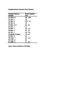
Definition: Ground pressure = tractor machine operating weight / total ground contact area where; total ground contact area = length of track on ground × shoe width × 2. Single grouser shoe Model D21A-7 D21P-7 D31EX-21 D31PX-21 D37EX-21 D37PX-21 D39EX-21 D39PX-21 D41E-6 D41P-6 D61EX-12 D61EX-12***
Shoe width mm (in.) 300 (11.8)* 340 (13.4) 510 (20.1) 400 (15.7) 600 (23.6) 400 (15.7) 600 (23.6) 460 (18.0)* 635 (25.0)* 700 (27.6) 510 (20.1)* 560 (22.0) 700 (27.6)* 600 (23.6) 600 (23.6)
Ground contact area m2 (in2) 1.01 (1570) 1.15 (1780) 1.72 (2660) 1.61 (2496) 2.62 (4061) 1.79 (2775) 2.69 (4170) 2.17 (3364) 3.00 (4646) 3.31 (5130) 2.54 (3930) 2.78 (4310) 3.84 (5960) 3.12 (4836) 3.80 (5890)
Ground pressure kg/cm2 (PSI/kPa) 0.31 (4.41/30.4) 0.28 (3.98/27.5) 0.20 (2.84/19.6) 0.36 (5.12/35.3) 0.24 (3.41/23.5) 0.34 (4.83/33.3) 0.23 (3.27/22.6) 0.32 (4.55/31.4) 0.24 (3.41/23.5) 0.22 (3.13/21.6) 0.35 (4.98/34.3) 0.31 (4.41/30.4) 0.24 (3.41/23.5) 0.42 (5.97/41.2) 0.36 (5.12/35.3)
Model D61PX-12 D65E-12
D65EX-15
D65EX-15*** D65P-12 D65PX-15 D68ESS-12
* : Standard shoe *** : With inside power angle-tilt dozer *** : Long track spec.
Single grouser shoe Model D70LE-8 D85ESS-2 D85ESS-2A
D85EX-15 D85PX-15 D155A-5
D155AX-5
D155A-2A
Shoe width mm (in.) 610 (24.0) * 610 (24.0) * 510 (20.1) * 560 (22.0) 610 (24.0) 560 (22.0) * 610 (24.0) 660 (26.0) 910 (36.0)* 560 (22.0) * 610 (24.0) 660 (26.0) 710 (28.0) 560 (22.0) * 610 (24.0) 660 (26.0) 710 (28.0) 560 (22.0) * 610 (24.0) 660 (26.0) 710 (28.0)
Ground contact area m2 (in2) 3.21 (4980) 3.64 (5640) 3.04 (4710) 3.34 (5180) 3.64 (5640) 3.42 (5295) 3.72 (5760) 3.75 (5810) 6.33 (9820) 3.60 (5580) 3.92 (6080) 4.24 (6570) 4.56 (7070) 3.60 (5580) 3.92 (6080) 4.24 (6570) 4.56 (7070) 3.53 (5470) 3.84 (5960) 4.16 (6440) 4.47 (6930)
Ground pressure kg/cm2 (PSI/kPa)
Application**
0.43 (6.11/42.2) 0.43 (6.11/42.2) 0.51 (7.25/50.0) 0.47 (6.68/46.1) 0.43 (6.11/42.2) 0.62 (8.82/60.8) 0.57 (8.11/55.9) 0.51 (7.25/50.0) 0.37 (5.26/36.3) 0.78 (11.09/76.5) 0.72 (10.23/70.6) 0.67 (9.53/65.7) 0.63 (8.96/61.8) 0.82 (11.66/80.4) 0.76 (10.81/74.5) 0.70 (9.95/68.6) 0.68 (9.67/66.7) 0.79 (11.23/77.5) 0.73 (10.38/71.6) 0.68 (9.67/66.7) 0.64 (9.10/62.7)
B B A A B A B B C A B B C A B B C A B B C
* : Standard shoe ** : See the classification of shoe application
1A-16
Shoe width mm (in.) 860 (33.9)* 510 (20.1)* 560 (22.0) 610 (24.0) 660 (26.0) 510 (20.1)* 560 (22.0) 610 (24.0) 660 (26.0) 510 (20.1)* 560 (22.0) 610 (24.0) 915 (36.0)* 915 (36.0)* 610 (24.0)*
Ground contact area m2 (in2) 5.45 (8447) 2.73 (4230) 3.00 (4650) 3.26 (5050) 3.53 (5473) 2.73 (4230) 3.00 (4650) 3.26 (5050) 3.53 (5470) 3.35 (5195) 3.68 (5702) 4.01 (6210) 6.01 (9320) 6.01 (9320) 3.57 (5635)
Ground pressure kg/cm2 (PSI/kPa) 0.27 (3.84/26.5) 0.57 (8.11/55.9) 0.53 (7.54/52.0) 0.49 (6.97/48.1) 0.45 (6.40/44.1) 0.60 (8.53/58.8) 0.55 (7.82/53.9) 0.51 (7.22/49.8) 0.47 (6.68/46.1) 0.51 (7.25/50.0) 0.47 (6.65/45.9) 0.43 (6.16/42.5) 0.28 (3.98/25.4) 0.29 (4.12/28.4) 0.53 (7.54/52.0)
AH_25.book Page 17 Tuesday, March 23, 2004 9:41 AM
Ground Pressure
CRAWLER-TYPE TRACTORS
Definition: Ground pressure = tractor machine operating weight / total ground contact area where; total ground contact area = length of track on ground × shoe width × 2. Extreme service shoe Model
D155A-5
D155AX-5
D155A-2A
D275A-5
D275AX-5
D375A-5
D475A-5 D475A-5 SD D575A-3
D575A-3 SD
Shoe width mm (in.) 560 (22.0) 610 (24.0) 660 (26.0) 560 (22.0) 610 (24.0) 660 (26.0) 560 (22.0) 610 (24.0) 660 (26.0) *610 (24.0) 710 (28.0) 810 (31.9) *610 (24.0) 710 (28.0) 810 (31.9) *610 (24.0) 710 (28.0) 760 (29.9) *710 (28.0) 810 (31.9) 910 (35.8) *810 (31.9) 910 (35.8) 760 (29.9) 810 (31.9) *860 (33.9) 910 (35.8) *860 (33.9) 910 (35.8)
Ground contact area m2 (in2) 3.60 (5580) 3.92 (6080) 4.24 (6570) 3.60 (5580) 3.92 (6080) 4.24 (6570) 3.53 (5470) 3.84 (5960) 4.16 (6440) 4.25 (6590) 4.94 (7660) 5.29 (8200) 4.25 (6590) 4.94 (7660) 5.29 (8200) 4.69 (7260) 5.45 (8450) 6.22 (9640) 6.20 (9610) 7.07 (10960) 7.94 (12340) 7.07 (10960) 7.94 (12340) 6.89 (10670) 7.34 (11380) 7.79 (12080) 8.25 (12780) 9.43 (14620) 9.98 (15470)
Ground pressure kg/cm2 (PSI/kPa)
**Application
0.79 (11.23/77.5) 0.73 (10.38/71.6) 0.68 (9.67/66.7) 0.83 (11.80/81.4) 0.77 (10.95/75.5) 0.72 (10.24/70.6) 0.80 (11.38/78.5) 0.74 (10.52/72.6) 0.69 (9.81/67.6) 0.89 (12.66/87.3) 0.77 (10.95/75.5) 0.73 (10.38/71.6) 0.89 (12.66/87.3) 0.77 (10.95/75.5) 0.73 (10.38/71.6) 1.06 (15.07/104.0) 0.93 (13.22/91.2) 0.82 (11.66/80.4) 1.27 (18.1/124.5) 1.13 (16.1/110.8) 1.01 (14.4/99.0) 1.13 (16.1/110.8) 1.02 (14.5/100.0) 1.41 (19.1/137.3) 1.33 (18.8/129.4) 1.26 (17.8/122.6) 1.19 (16.9/116.7) 1.22 (17.3/119.6) 1.15 (16.4/112.8)
A B B A B B A B B A B B A B B A B C A B C A,B D A B B C A,B B
* : Standard shoe ** : See the classification of shoe application
Swamp shoe (Circular arc shape) Model
Shoe width mm (in.)
D31PX-21 D37PX-21 D39PX-21 D41P-6 D65P-12 D65PX-15 D85PX-15
600 (23.6) 600 (23.6) 700 (27.6) 700 (27.6)* 950 (37.4) 950 (37.4) 910 (36.0)*
Ground contact area m2 (in2) 2.62 (4061) 2.69 (4170) 3.30 (3800) 3.84 (6000) 6.24 (9670) 6.24 (9670) 6.33 (9820)
Ground pressure kg/cm2 (PSI/kPa) 0.24 (3.41/23.5) 0.24 (3.41/23.5) 0.22 (3.13/21.6) 0.23 (3.27/22.6) 0.27 (3.98/25.4) 0.28 (3.95/27.3) 0.37 (5.26/36.3)
* : Standard shoe ** : With inside power angle-tilt dozer
1A-17
AH_25.book Page 18 Tuesday, March 23, 2004 9:41 AM
Shoe Application
CRAWLER-TYPE TRACTORS
Classification of the applications: Classification
Applicable terrain
A
Rocky terrain, general terrain
B
General or soft terrain
C
Extremely soft terrain (swamps)
Limitations These can be used over a wide range of general civil engineering work from crushed rock to preparation of residential land. There is no particular limitation on their use. These are used for general earthmoving work where the main work is scraping operations and pushing operations when constructing golf courses, and overburden stripping operations in coal mines. They cannot be used on rocky ground. Be careful to avoid traveling over rocks when carrying out operations on job sites where there are scattered rocks. These are used on soft ground where B classification shoes would sink. These cannot be used on ground where there are scattered rocks.
NOTE: Select the proper shoe width for your customers, by taking the limitations described above into consideration, (especially on wide shoes "B" and "C"). Select the narrowest possible shoes, depending on the flotation and ground pressure of the machines. If the shoe is too wide, the load on the track shoe increases and results in bends in the shoes, cracks in the links, breakage and slipping out of the pins and loosening of the bolts.
1A-18
AH_25.book Page 19 Tuesday, March 23, 2004 9:41 AM
Shoe Selection
CRAWLER-TYPE TRACTORS
Applications of different shoes in accordance with soil characteristics and working conditions. Type of shoe
Applicable soil and work
1 Single grouser shoe
General soil excluding rocky ground (for bulldozer)
2 Heavy duty shoe
For rocky ground (for bulldozer)
3 • Tripple grouser shoe • Double grouser shoe
Advantages • Because the shape of the grouser is sharp, it easily bites into the ground and provides a large traction force.
Disadvantages • Strength is somewhat reduced on rocky ground, and bending and other damage may occur. • The riding conform is a little inferior to the triple and double grouser shoes. • The road surface is liable to be roughed. • The turning resistance is large.
Remarks Is available in various widths to suit the softness of the soil.
• Compared to a single grouser shoe, the grouser and plate portions of this shoe are thicker and stronger, providing high bending resistance and wear resistance.
• The three grousers have • This shoe does not readily the same height, hence bite into the ground, so the turning ability is good. traction force is low. Hard ground • Good riding comfort is Suitable for both soft obtained as compared with and hard ground a single grouser shoe. (for hydraulic excavator and dozer • Rotating resistance is low. • Because three beams are shovel) used, resistance to bending is high.
Swamp areas (for swamp dozer)
• Because the cross-section • Unsuitable for ground other of this shoe is an arc, the than swampy ground. ground contact area is When used off swampy large, and buoyancy is ground, it is liable to bend easily obtained. due to its low strength. • This shoe is particularly suitable for use in swamp areas and areas with low ground pressure. The ground surface is not damaged when the machine travels over it, so it is suitable for soil compaction and leveling work. • Wear and damage occur rapidly when this shoe is used on general soil and rocky ground.
On snow
• For use on snow • To prevent transverse slip 1) Is provided with rib. 2) Grousers are stepped. • For discharging ice and snow 1) Holes are provided in plate portion. 2) Tail of plate has been eliminated.
• Because there are no grousers, this shoe does not bite into the ground.
Paved roads Indoor work
• Projections have been eliminated (heads of shoe bolts are recessed), permitting work on paved roads without damaging road surface. • Turning resistance is very low, and tracks are highly wear resistant.
4 Swamp shoe
5 Snow shoe
6 Flat shoe
1A-19
Various widths are available to suit the degree of softness of the swampy ground.
AH_25.book Page 20 Tuesday, March 23, 2004 9:41 AM
Shoe Selection
Type of shoe
Applicable soil and work
7 Road liner (rubber)
Paved road Indoor work
8 Center hole shoe
Soil which clogs
Advantages
CRAWLER-TYPE TRACTORS Disadvantages
• The surface of the shoe in • Use in the following places contact with the ground is will shorten the cutting life made of rubber, so the of the rubber. machine can travel on (1) Rocky ground paved roads without (2) Cold areas damaging the road (below -25ºC) surface. (3) Hot areas • Prevents noise when (above 65ºC) machine is traveling. • Because there are no grouser, this shoe does not bite into the ground. • There is a hole in the plate • Strength is somewhat to remove any mud or soil. reduced on rocky ground, • The sprocket removes any and crack and other mud or soil collected damage may occur. between the track rails, so clogging of the track is reduced.
1A-20
Remarks
AH_25.book Page 21 Tuesday, March 23, 2004 9:41 AM
Roller Guard Installation
CRAWLER-TYPE TRACTORS
Roller guard installation (Bulldozer) Small-middle Class When using bulldozers, it is necessary to make most appropriate choices of the track roller guards fitting to respective working environments. Given below are the criterion for the choices. This chart provides clearer criterion for the choices in consideration of respective functions of different types of track roller guards. Types
Full roller guard 3-part split type full roller guard
Integral structure full roller guard
Determination criterion for different working environments Rocks and soil containing boulders and gravel (A and E) Sand and sandy soil (A, E and P) Clayey soil (P and PL) Swamp (PL and PLL) Slopes
Local add-on type The part is effective for prevention of catching pebbles. The part is effective for prevention of pitch squeaking. Be careful when using this part since the soil sets when dried. (Note 1) The part is effective for prevention of snaking of the track. (Prevents side sliding of the track shoes.) (Note 1) The part is effective for prevention of disengagement of the track shoes. The part is effective for prevention of disengagement of the track shoes. (Prevents side-sliding of the track shoes.)
(Note 1) Although soil and sand tend to enter less, once they enter, they may not be easily discharged depending on the type of soil, so make the choice in consideration of past experience with machines having been used in the subject area and of the working environments of the machine.
Types Center and end section track guard
Determination criterion for different working environments Rocks and soil containing boulders and gravel (A and E) Sand and sandy soil (A, E and P) Clayey soil (P and PL) Swamp (PL and PLL) Slopes
Not full roller guard End section track guard
Short length guard for installation at the center section The part is not suitable
The part is not suitable
No noticeable difference from use of the endsection only track guard The part is effective for prevention of disengagement or side-sliding of the track shoes The part is not suitable
Although sand and soil tend to enter more, they can be easily discharged and this part is being employed.
The part is not suitable
NOTE: Please consult your local distributor for availability of track rollers guard for the model that you require.
1A-21
AH_25.book Page 22 Tuesday, March 23, 2004 9:41 AM
Roller guard installation
CRAWLER-TYPE TRACTORS
Large Class When using bulldozers, it is necessary to make most appropriate choices of the track roller guards fitting to respective working environments. Given below are the criterion for the choices. This chart provides clearer criterion for the choices in consideration of respective functions of different types of track roller guards. Types
Full roller guard Split type full roller guard
Bogie full roller guard
Determination criterion for different working environments Rocks and soil containing boulders and gravel (A and E) Sand and sandy soil (A, E and P) Clayey soil (A, E and P) Slopes
The part is effective for prevention of catching pebbles. The part is effective for prevention of pitch squeaking. Be careful when using this part since the soil sets when dried. (Note 1) The part is effective for prevention of disengagement of the track shoes. (Prevents side-sliding of the track shoes.)
(Note 1) Although soil and sand tend to enter less, once they enter, they may not be easily discharged depending on the type of soil, so make the choice in consideration of past experience with machines having been used in the subject area and of the working environments of the machine.
Types
Not full roller guard Add-on full roller guard
Bogie roller guard
Determination criterion for different working environments Rocks and soil containing boulders and gravel (A and E) Sand and sandy soil (A, E and P)
Although sand and soil tend to The part prevents stones from enter more, they can be easily entering between rollers on discharged and this part is the rocky soil being employed. The part is effective for prevention of disengagement or side-sliding of the track shoes.
Clayey soil (A, E and P)
Slopes
The part is not suitable
Center end section track guard
The part is not suitable
Although sand and soil tend to enter more, they can be easily discharged and this part is being employed. The part is effective for prevention of disengagement or side-sliding of the track shoes. The part is not suitable
NOTE: Please consult your local distributor for availability of track rollers guard for the model that you require.
1A-22
AH_25.book Page 23 Tuesday, March 23, 2004 9:41 AM
CRAWLER-TYPE TRACTORS
OVERALL HEIGHT
Upper Attachment
G.L
Item Mode D21A-8 D21P-8 D31EX-21 D31PX-21 D37EX-21 D37PX-21 D39EX-21 D39PX-21 D41E-6 D41P-6 D61EX-12 D61PX-12 D65E, P-12 D65EX, PX-15 D85ESS-2A D85EX-15 D85PX-15 D155A-5 D155AX-5B D155A-2A D275A-5 D275AX-5 D375A-5 D475A-5 D575A-3 D575A-3 SD * ** *** *4
Canvas or plastic canopy
Weight kg (lb) *ROPS canopy
*ROPS cab
70 (150)
310 (680)
566 (1,250)
—
310 (680)
650 (1,430)
—
2700 (8'10")
2700 (8'10")
—
310 (680)
650 (1,430)
—
2700 (8'10")
2700 (8'10")
—
330 (730)
670 (1,480)
—
2770 (9'1")
2770 (9'1")
110 (240)
340 (750)***
590 (1,300)*4
2715 (8'11")
2885 (9'6")
2885 (9'6")
—
330 (730)***
580 (1,280)*4
—
3115 (10'3")
3115 (10'3")
140 (310) — 140 (310)
420 (930)*** 390 (860)*** 420 (930)***
*4
760 (1,675) 730 (1,610)*4 760 (1675)*4
2995 (9'10") — 2995 (9'10")
—
437 (970)***
781 (1730)*4
—
3165 (10'5") 3220 (10'7") 3165 (10'5") 3340 (10'11") 3377 (11'1")
3165 (10'5") 3220 (10'7") 3165 (10'5") 3324 (10'11") 3361 (11')
—
505 (1,110)***
790 (1,740)
—
3500 (11'6")
3500 (11'6")
*4
Overall height mm (ft.in) ROPS Canvas or ROPS plastic canopy cab canopy 2475 (8'1") 2450 (8') 2450 (8') 2500 (8'2") 2475 (8'1") 2475 (8'1")
—
970 (2,140)
3725 (12'3")
3750 (12'4")
3750 (12'4")
—
650 (1,430)***
1065 (2,350)*4
—
3985 (13'1")
3985 (13'1")
— — — —
760 (1,680)*** 940 (2070)*** 1970 (4,340)*** 1970 (4,340)***
1175 (2,590) 1395 (3,075)*4 2450 (5,400)*4 2450 (5,400)*4
— — — —
4230 (13'11") 4590 (15'1") 4880 (16') 4880 (16')
4230 (13'11") 4590 (15'1") 4880 (16') 4880 (16')
1430 (3,150)
*4
: With ROPS brackets, except D65-12 and D85ESS-2A : With inside power angle-tilt dozer : Two-pole type : ROPS canopy & steel cab
1A-23
AH_25.book Page 24 Tuesday, March 23, 2004 9:41 AM
MEMO
AH_25.book Page 1 Tuesday, March 23, 2004 9:41 AM
SECTION
1B
BULLDOZERS CONTENTS Blade selection ......................................................... 1B-2 Blade availability ...................................................... 1B-3 Blade specifications: Straight-tiltdozer .................................................. 1B-5 Angledozer ........................................................... 1B-6 Power angle-tiltdozer .......................................... 1B-8 Semi-U-tildozer .................................................. 1B-11 U-tildozer ............................................................ 1B-13 Super dozer ........................................................ 1B-14 Coal dozer .......................................................... 1B-15 Production .............................................................. 1B-16
1B-1
AH_25.book Page 2 Tuesday, March 23, 2004 9:41 AM
Blade Selection
BULLDOZERS
Straight-tilltdozer Having a high HP/ cutting edge length, this blade has an aggressive penetration. This blade also has a high HP/loose cubic yards for easy handling of heavy materials. The tilting function of this blade increases production and versatility. With a sturdy construction, this blade is suitable for powerful cutting and dozing, especially heavy cutting on rocky ground.
Straight dozer This blade has the same structure and functions but is not equipped with a tilt-cylinder.
Angle dozer The blade can be set straight or angled to both sides. Plowing earth or snow to one side is possible by angling the blade. Useful for road construction, back filling etc.
Power angle-tiltdozer Power angling and tilting of the blade are possible from the operator seat. This blade is applicable for versatile works such as grading, back filling, spreading and light land clearing
Dual tiltdozer The blade has two tilt cylinders on both sides. An optimum blade cutting angle for all types of materials and ground inclinations can be selected for increased loads and consequently increased production. A fast tilt speed and a large tilt angle also concentrate blade force where maximum penetration is needed.
Semi U-tiltdozer The blade combines penetration ability of straight blade with increased load capacity provided by short wings which include only the end bits.
U-tiltdozer The wings on this blade minimize material spillage. Since this blade has a lower HP/loose cubic yards than a straight-tiltdozer, this blade is suitable for moving lighter or loose materials over long distances. Suitable works are land reclamation, stockpiling and other similar jobs.
Coal dozer Specialized blade for pushing coal, with larger width and deep angled wings.
FVBH0199
Rake-dozer Having teeth, this blade provides good penetration into the soil for removal of stumps, roots and rocks. 1B-2
AH_25.book Page 3 Tuesday, March 23, 2004 9:41 AM
Blade Availability
Model Attachment Straight-tiltdozer Strengthened straight-tiltdozer Straightdozer Strengthened straightdozer Angle dozer Strengthened angle dozer Power angle-tiltdozer Wide power angle-tiltdozer Mechanical angle power tiltdozer Semi-U-tiltdozer Strengthened semi-U-tiltdozer U-tiltdozer Mechanical tilt coaldozer Power tilt coaldozer Cushiondozer Welded type pusher plate Bolt-on type pusher plate Angle-rakedozer Straight-rakedozer Shear blade Trimming dozer Straight-rock rakedozer Power tilt and pitch dozer Model Attachment
D21-7 A P
D31-21 EX PX
D65-12 E
P
D37-21 EX PX
D65-15 EX
PX
Straight-tiltdozer Strengthened straight-tiltdozer Straight dozer Strengthened straight dozer Angle dozer Strengthened angle dozer Power angle-tiltdozer Mechanical angle power tiltdozer Semi-U-tiltdozer Strengthened semi-U-tiltdozer U-tiltdozer Strengthened U-tiltdozer Mechanical tilt coal dozer Power tilt coal dozer Cushion dozer Welded type pusher plate Bolt-on type pusher plate Angle-rake dozer Straight-rake dozer Shear blade Trimming dozer Straight rock rake dozer Semi-U-dual tiltdozer Strengthened semi-U-dual tiltdozer U-dual tiltdozer Strengthened U-dual tiltdozer Power tilt and pitch dozer *
: With inside Power Angle-tilt Dozer
1B-3
BULLDOZERS
D39-21 EX PX
D68-12
D70
ESS
LE
D41-6 E P
D85-2 D85-2A ESS
ESS
D61-12 EX PX
D85-15 EX
PX
AH_25.book Page 4 Tuesday, March 23, 2004 9:41 AM
Blade Availability
Model Attachment Straight-tiltdozer Strengthened straight-tiltdozer Straight dozer Strengthened straight dozer Angle dozer Strengthened angle dozer Power angle-tiltdozer Mechanical angle power tiltdozer Semi-U-tiltdozer Strengthened semi-U-tiltdozer U-tiltdozer Strengthened U-tiltdozer Mechanical tilt coal dozer Power tilt coal dozer Cushion dozer Welded type pusher plate Bolt-on type pusher plate Angle-rake dozer Straight-rake dozer Shear Blade Trimming dozer Straight rock rake dozer Semi-U-dual tiltdozer Strengthened semi-U-dual tiltdozer U-dual tiltdozer Strengthened U-dual tiltdozer Super dozer
D155-5 A AX
D155-2A
A
D275-5 A AX
1B-4
BULLDOZERS
D375-5
A
D475-5 A A-5SD
D575-3 A A-3SD
AH_25.book Page 5 Tuesday, March 23, 2004 9:41 AM
Blade Specifications Straight-tiltdozer
BULLDOZERS
C
D
F
G.L E
B
Item OPERATING WEIGHT* BLADE CAPACITY
LH2** SAE
DIMENSION* A Overall length B Overall width C Overall height Ground pressure DOZER EQUIPMENT Weight (Includes hydraulic control unit) Length Height D Max. lift above ground E Max. drop below ground F Max. tilting adjustment Digging angle
Item OPERATING WEIGHT* BLADE CAPACITY
LH2** SAE
DIMENSION* A Overall length B Overall width C Overall height Ground pressure DOZER EQUIPMENT Weight (Includes hydraulic control unit) Length Height D Max. lift above ground E Max. drop below ground F Max. tilting adjustment Digging angle
A
Model
D65E-12
D65P-12
D65EX-15
D65PX-15
kg (lb)
17470 (38,510)
18860 (41,580)
19070 (42,040)
20700 (45,635)
m3 (yd3)
5.12 (6.70) 3.89 (5.09)
4.80 (6.28) 3.69 (4.83)
5.12 (6.70) 3.89 (5.09)
4.80 (6.28) 3.69 (4.83)
mm (ft.in) mm (ft.in) mm (ft.in) kg/cm2 (PSI)
5260 (17'3") 3415 (11'2") 2980 (9'9") 0.64 (9.10)
5550 (18'3") 3970 (13') 3025 (9'11") 0.30 (4.27)
5260 (17'3") 3415 (11'2") 2990 (9'10") 0.70 (9.95)
5220 (18'1") 3970 (13') 2990 (9'10") 0.33 (4.69)
kg (lb)
2600 (5,730) 2720 (6,000) 3415 (11'2") 1225 (4'1") 1100 (3'7") 450 (1'6") 870 (2'10") 55
2620 (5,780)
2720 (5,995)
2740 (6,040)
3970 (13') 1100 (3'7") 1200 (3'11") 445 (1'6") 890 (2'11") 57
3415 (11'2") 1225 (4'0") 1105 (3'8") 440 (1'5") 870 (2'10") 55
3970 (13'0") 1100 (3'7") 1105 (3'8") 540 (1'9") 450 (1'6") 57
mm (ft.in) mm (ft.in) mm (ft.in) mm (ft.in) mm (ft.in) degree Model
D85E-SS-2A
D85EX-15
D85PX-15
kg (lb)
18230 (40,190)
24370 (53,730)
26690 (58,840)
m3 (yd3)
6.1 (7.98) 4.4 (5.76)
7.7 (10.07) 5.2 (6.8)
8.2 (10.73) 5.9 (7.7)
mm (ft.in) mm (ft.in) mm (ft.in) kg/cm2 (PSI)
5615 (18'5") 3620 (11'11") 2980 (9'9") 0.60 (8.53)
5640 (18'6") 3715 (12'2") 3330 (10'11") 0.74 (10.5)
6065 (19'11") 4365 (14'4") 3330 (10'11") 0.43 (6.1)
kg (lb)
2810 (6,190)
3305 (7,290)
3345 (7,375)
mm (ft.in) mm (ft.in) mm (ft.in) mm (ft.in) mm (ft.in) degree
3620 (11'11") 1295 (4'3") 1070 (3'6") 590 (1'11") 920 (3') 55
3715 (12'2") 1436 (4'9") 1207 (4') 540 (1'9") 750 (2'6") 55
4365 (14'4") 1370 (4'6") 1222 (4') 568 (1'10") 500 (1'8") 55
* : Including dozer equipment in addition to bare tractor, excluding ROPS and cab. ** : L: Blade length H: Blade height
1B-5
AH_25.book Page 6 Tuesday, March 23, 2004 9:41 AM
Blade Specifications Angledozer
BULLDOZERS
C
D F G.L E
B
Item OPERATING WEIGHT* BLADE CAPACITY
LH2** SAE
DIMENSION* A Overall length B Overall width C Overall height Ground pressure DOZER EQUIPMENT Weight (Includes hydraulic control unit) Length Height D Max. lift above ground E Max. drop below ground F Max. tilting adjustment Digging angle
Item OPERATING WEIGHT* BLADE CAPACITY
LH2** SAE
DIMENSION* A Overall length B Overall width C Overall height Ground pressure DOZER EQUIPMENT Weight (Includes hydraulic control unit) Length Height D Max. lift above ground E Max. drop below ground F Max. tilting adjustment Digging angle
A
Model
D68ESS-12***
D65E-12
D65EX-15
D70LE-6***
kg (lb)
19100 (42,110)
17690 (39,000)
19280 (42,110)
19970 (44,030)
m3 (yd3)
3.6 (4.71) 2.6 (3.40)
4.80 (6.28) 3.55 (4.64)
4.80 (6.28) 3.55 (4.64)
4.5 (5.89) 3.1 (4.05)
mm (ft.in) mm (ft.in) mm (ft.in) kg/cm2 (PSI)
5930 (19'5") 3970 (13') 3140 (10'4") 0.54 (7.68)
5470 (17'11") 3970 (13') 2980 (9'9") 0.65 (9.2)
5470 (17'11") 3970 (13') 2990 (9'10") 0.71 (10.1)
5230 (17'2") 4100 (13'5") 3020 (9'11") 0.53 (7.54)
kg(lb)
2660 (5,860)
2930 (5,860)
3090(6,810)
mm (ft.in) mm (ft.in) mm (ft.in) mm (ft.in) mm (ft.in) degree
3970 (13') 950 (3'1") 1205 (3'11") 535 (1'9") 400 (1'4") 50
2820 (6,220) 2930 (6,460) 3970 (13') 1100 (3'7") 1180 (3'10") 460 (1'6") 400 (1'4") 56.5
3970 (13') 1100 (3'7") 1185 (3'11") 450 (1'6") 400 (1'4") 56.5
4100 (13'5") 1050 (3'5") 1130 (3'8") 585 (1'11") 400 (1'4") 55
Model
D85ESS-2***
D85ESS-2A
D85A-21
kg (lb)
21490 (47,390)
18850 (41,560)
23320 (51,410)
m3 (yd3)
5.0 (6.54) 3.4 (4.45)
5.0 (6.54) 3.4 (4.45)
5.6 (7.32) 3.9 (5.10)
mm (ft.in) mm (ft.in) mm (ft.in) kg/cm2 (PSI)
5930 (19'5") 4370 (14'4") 2560 (8'5") 0.52 (7.39)
5930 (19'5") 4370 (14'4") 2980 (9'9") 0.62 (8.82)
5810 (19'1") 4365 (14'4") 3365 (11') 0.73 (10.38)
kg (lb)
2890 (6,370)
3430 (7,560)
4610 (10,160)
mm (ft.in) mm (ft.in) mm (ft.in) mm (ft.in) mm (ft.in) degree
4370 (14'4") 1070 (3'6") 1255 (4'1") 485 (1'7") 400 (1'4") 56
4370 (14'4") 1070 (3'6") 1255 (4'1") 485 (1'7") 400 (1'4") 56
4365 (14'4") 1130 (3'8") 1310 (4'4") 560 (1'10") 500 (1'8") 55.6
* : Including dozer equipment in addition to bare tractor, excluding ROPS and cab. ** : L: Blade length H: Blade height *** : With winch and sweep canopy
1B-6
AH_25.book Page 7 Tuesday, March 23, 2004 9:41 AM
Blade Specifications Angledozer
BULLDOZERS
C
D F G.L E
B
Item OPERATING WEIGHT* BLADE CAPACITY
LH2** SAE
DIMENSION* A Overall length B Overall width C Overall height Ground pressure DOZER EQUIPMENT Weight (Includes hydraulic control unit) Length Height D Max. lift above ground E Max. drop below ground F Max. tilting adjustment Digging angle
Item OPERATING WEIGHT* BLADE CAPACITY
LH2** SAE
DIMENSION* A Overall length B Overall width C Overall height Ground pressure DOZER EQUIPMENT Weight (Includes hydraulic control unit) Length Height D Max. lift above ground E Max. drop below ground F Max. tilting adjustment Digging angle
A
Model
D85A-21B
D85E-21
D155A-2A
D155A-5
kg (lb)
22860 (50,400)
23680 (52,200)
34390 (75,820)
33040 (72,840)
m3 (yd3)
5.6 (7.32) 3.9 (5.10)
5.6 (7.32) 3.9 (5.10)
6.30 (8.64) 4.58 (5.99)
7.00 (9.16) 4.9 (6.4)
mm (ft.in) mm (ft.in) mm (ft.in) kg/cm2 (PSI)
6100 (20') 4365 (14'4") 3365 (11') 0.75 (10.67)
6020 (19'9") 4365 (14'4") 3365 (11') 0.69 (9.81)
6620 (21'9") 4850 (15'11") 3725 (12'3") 0.975 (13.86)
6502 (21'4") 4850 (15'11") 3395 (11'2") 0.92 (13.1)
kg (lb)
4610 (10,160)
4610 (10,160)
6520 (14,370)
5140 (11,330)
mm (ft.in) mm (ft.in) mm (ft.in) mm (ft.in) mm (ft.in) degree
4635 (14'4") 1130 (3'8") 1310 (4'4") 560 (1'10") 500 (1'8") 55.6
4365 (14'4") 1130 (3'8") 1425 (4'8") 580 (1'11") 500 (1'8") 55.6
4850 (15'11") 1140 (3'9") 1520 (5') 630 (2'1") 400 (1'4") 55
4850 (15'11") 1205 (3'11") 1295 (4'3") 745 (2'5") 520 (1'8") 55
Model
D155AX-5
kg (lb)
34540 (76,150)
m3 (yd3)
7.00 (9.16) 4.9 (6.4)
mm (ft.in) mm (ft.in) mm (ft.in) kg/cm2 (PSI)
6510 (21'4") 4850 (15'11") 3395 (11'2") 0.96 (13.65)
kg (lb)
5140 (11,330)
mm (ft.in) mm (ft.in) mm (ft.in) mm (ft.in) mm (ft.in) degree
4850 (15'11") 1205 (3'11") 1295 (4'3") 745 (2'5") 520 (1'8") 55
* : Including dozer equipment in addition to bare tractor, excluding ROPS and cab. ** : L: Blade length H: Blade height
1B-7
AH_25.book Page 8 Tuesday, March 23, 2004 9:41 AM
Blade Specifications Power Angle-tiltdozer
BULLDOZERS
C
D G.L
F E A
B
Model
Item OPERATING WEIGHT* BLADE CAPACITY
D21P-8
D31EX-21
D31PX-21
3710 (8,180)
4100 (9,040)
6820 (15,040)
7340 (16,180)
m (yd )
0.76 (0.99) 0.57 (0.75)
0.89 (1.16) 0.68 (0.89)
1.74 (2.28) 1.49 (1.95)
1.80 (2.35) 1.55 (2.03)
mm (ft.in) mm (ft.in) mm (ft.in) kg/cm2 (PSI)
3250 (10'8") 2170 (7'11") 2315 (7'7") 0.37 (5.26)
3260 (10'8") 2560 (8'5") 2335 (7'8") 0.24 (3.41)
4015 (13'2") 2435 (8'0") 2645 (8'8") 0.42 (5.97)
3995 (13'1") 3200 (10'6") 2645 (8'8") 0.28 (3.98)
kg (lb)
Inside mount 550 (1,210)
Inside mount 580 (1280)
Inside mount 1045 (2,300)
Inside mount 1120 (2,470)
mm (ft.in) mm (ft.in) mm (ft.in) mm (ft.in) mm (ft.in)
2170 (7'11") 590 (1'11") 790 (2'7") 385 (1'3") 250 (9'8")
2560 (8'5") 590 (1'11") 850 (2'9") 325 (1'1") 280 (11")
2435 (8'0") 845 (2'9") 860 (2'10") 385 (1'3") 330 (1'1")
3200 (10'6") 750 (2'6") 855 (2'10") 380 (1'3") 435 (1'5")
degree
25/25
25/25
25/25
25/25
D37EX-21
D37PX-21
D39EX-21
D39PX-21
kg (lb)
7100 (15,650)
7460 (16,450)
8210 (18,100)
8590 (18,940)
m3 (yd3)
2.04 (3.24) 1.75 (2.29)
2.24 (3.52) 1.91 (2.50)
2.63 (3.14) 2.22 (2.90)
2.78 (3.40) 2.32 (3.03)
mm (ft.in) mm (ft.in) mm (ft.in) kg/cm2 (PSI)
4015 (13'2") 2720 (8'11") 2645 (8'8") 0.40 (5.69)
3995 (13'1") 3250 (10'8") 2645 (8'8") 0.28 (3.98)
4200 (13'9") 2740 (9'0") 2720 (8'11") 0.38 (5.40)
4200 (13'9") 3330 (10'11'') 2720 (8'11") 0.29 (4.12)
kg (lb)
Inside mount 1090 (2,400)
Inside mount 1150 (2,540)
Inside mount 1260 (2,780)
Inside mount 1360 (3,000)
mm (ft.in) mm (ft.in) mm (ft.in) mm (ft.in) mm (ft.in)
2720 (8'11") 865 (2'10") 860 (2'10") 385 (1'3") 375 (1'3")
3250 (10'8") 830 (2'9") 855 (2'10") 380 (1'3") 445 (1'6")
2740 (9'0") 980 (3'3") 890 (2'11") 440 (1'5") 395 (1'4")
3330 (10'11") 910 (3'0") 890 (2'11") 440 (1'5") 480 (1'7")
degree
25/25
25/25
25/25
25/25
kg (lb) 2
LH ** SAE
DIMENSION* A Overall length B Overall width C Overall height Ground pressure DOZER EQUIPMENT Type Weight (Includes hydraulic control unit) Length Height D Max. lift above ground E Max. drop below ground F Max. tilting adjustment Angling angle (L/R)
Item OPERATING WEIGHT* BLADE CAPACITY
D21A-8
LH2** SAE
DIMENSION* A Overall length B Overall width C Overall height Ground pressure DOZER EQUIPMENT Type Weight (Includes hydraulic control unit) Length Height D Max. lift above ground E Max. drop below ground F Max. tilting adjustment Angling angle (L/R)
3
3
Model
* : Including dozer equipment in addition to bare tractor, excluding ROPS and cab. ** : L: Blade length H: Blade height
1B-8
AH_25.book Page 9 Tuesday, March 23, 2004 9:41 AM
Blade Specifications Power Angle-tiltdozer
BULLDOZERS
C
D G.L
F E A
B
Model
Item OPERATING WEIGHT* BLADE CAPACITY
LH2** SAE
DIMENSION* A Overall length B Overall width C Overall height Ground pressure DOZER EQUIPMENT Type Weight (Includes hydraulic control unit) Length Height D Max. lift above ground E Max. drop below ground F Max. tilting adjustment Angling angle (L/R)
D41P-6
D41P-6***
10670 (25,145)
11170 (24,625)
11250 (24,805)
m3 (yd3)
3.4 (4.45) 2.6 (3.40)
3.8 (4.92) 2.9 (3.79)
3.4 (4.45) 2.6 (4.12)
3.8 (4.92) 2.9 (3.79)
mm (ft.in) mm (ft.in) mm (ft.in) kg/cm2 (PSI)
4880 (16') 3045 (10') 2675 (8'9") 0.42 (5.97)
4880 (16') 3350 (11') 2675 (8'9") 0.42 (5.97)
4880 (16') 3045 (10') 2675 (8'9") 0.29 (4.12)
4880 (16') 3350 (11') 2675 (8'9") 0.29 (4.12)
kg (lb)
Inside mount 1800 (3,965)
Inside mount 1880 (4,145)
Inside mount 1800 (3,965)
Inside mount 1880 (4,145)
3045 (10') 1060 (3'6") 1010 (3'4") 490 (1'7") L:485 (1'7") R:645 (2'1") 55/25
3350 (11') 1060 (3'6") 1010 (3'4") 490 (1'7") L:530 (1'9") R:710 (2'4") 55/25
3045 (10') 1060 (3'6") 1010 (3'4") 490 (1'7") L:485 (1'7") R:645 (2'1") 55/25
3350 (11') 1060 (3'6") 1010 (3'4") 490 (1'7") L:530 (1'9") R:710 (2'4") 30/25
D61EX-12
D61EX-12***
D61EX-12*4
D61PX-12
15470 (34,110)
15630 (34,460)
16250 (35,820)
17180 (32,880)
3.4 (4.4)
3.8 (5.0)
3.4 (4.4)
3.8 (5.0)
mm (ft.in) mm (ft.in) mm (ft.in) kg/cm2 (PSI)
5030 (16'6") 3275 (10'9") 2945 (9'8") 0.50 (7.11)
5030 (16'6") 3860 (12'8") 2945 (9'8") 0.50 (7.11)
5440 (17'10") 3275 (10'9") 2945 (9'8") 0.43 (6.11)
5440 (17'10") 3860 (12'8") 2945 (9'8") 0.32 (4.55)
kg (lb)
Inside mount 2340 (5,160)
Inside mount 2500 (5,510)
Inside mount 2480 (5,470)
Inside mount 2630 (5,800)
mm (ft.in) mm (ft.in) mm (ft.in) mm (ft.in) mm (ft.in)
3275 (10'9") 1200 (3'11") 915 (3') 515 (1'8") 510 (1'8")
3860 (12'8") 1160 (3'10") 915 (3') 515 (1'8") 600 (2')
3275 (10'9") 1200 (3'11") 1045 (3'5") 550 (1'10") 515 (1'8")
3860 (12'8") 1160 (3'10") 1020 (3'4") 575 (1'11") 600 (2')
degree
25/25
25/25
25/25
25/25
mm (ft.in) mm (ft.in) mm (ft.in) mm (ft.in) mm (ft.in) degree
kg (lb) 2
LH ** SAE
DIMENSION* A Overall length B Overall width C Overall height Ground pressure DOZER EQUIPMENT Type Weight (Includes hydraulic control unit) Length Height D Max. lift above ground E Max. drop below ground F Max. tilting adjustment Angling angle (L/R) * ** *** *4
D41E-6***
10590 (23,345)
Model
Item OPERATING WEIGHT* BLADE CAPACITY
D41E-6
kg (lb)
3
3
m (yd )
: Including dozer equipment in addition to bare tractor, excluding ROPS and cab. : L: Blade length H: Blade height : With wide power angle-tiltdozer : Long track spec.
1B-9
AH_25.book Page 10 Tuesday, March 23, 2004 9:41 AM
Blade Specifications Power Angle-tiltdozer
BULLDOZERS
C
D G.L
F E A
B
Item OPERATING WEIGHT* BLADE CAPACITY
LH2** SAE
DIMENSION* A Overall length B Overall width C Overall height Ground pressure DOZER EQUIPMENT Type Weight (Includes hydraulic control unit) Length Height D Max. lift above ground E Max. drop below ground F Max. tilting adjustment Angling angle (L/R) * ** *** *4
Model kg (lb) m3 (yd3)
D68ESS-12*4 18,800 (41,500) 3.4 (4.45)
mm (ft.in) mm (ft.in) mm (ft.in) kg/cm2 (PSI)
6,120 (20'1") 3,275 (10'9") 3,135 (10'3") 0.53 (7.53)
kg (lb)
Inside mount 2,360 (5,205)
mm (ft.in) mm (ft.in) mm (ft.in) mm (ft.in) mm (ft.in)
3276 (10'9") 1200 (3'11") 1045 (3'5") 560 (1'10") 510 (1'9")
degree
25/25
: Including dozer equipment in addition to bare tractor, excluding ROPS and cab. : L: Blade length H: Blade height : With wide power angle-tiltdozer : With winch and sweep canopy
1B-10
AH_25.book Page 11 Tuesday, March 23, 2004 9:41 AM
Blade Specifications Semi-U-tiltdozer
Item OPERATING WEIGHT* BLADE CAPACITY
LH2** SAE
DIMENSION* A Overall length B Overall width C Overall height Ground pressure DOZER EQUIPMENT Weight (Includes hydraulic control unit) Length Height D Max. lift above ground E Max. drop below ground F Max. tilting adjustment
Item OPERATING WEIGHT* BLADE CAPACITY
LH2** SAE
DIMENSION* A Overall length B Overall width C Overall height Ground pressure DOZER EQUIPMENT Weight (Includes hydraulic control unit) Length Height D Max. lift above ground E Max. drop below ground F Max. tilting adjustment
Model
BULLDOZERS
D61EX-12
D65E-12
D65EX-15
D65EX-15 LT
kg (lb)
15510 (34,190)
18500 (40,780)
19350 (42,600)
20090 (44,290)
m3 (yd3)
5.4 (7.1) 4.3 (5.6)
6.8 (8.9) 5.6 (7.3)
7.03 (9.19) 5.61 (7.34)
7.03 (9.19) 5.61 (7.34)
mm (ft.in) mm (ft.in) mm (ft.in) kg/cm2 (PSI)
5050 (16'7") 3175 (10'5") 2945 (8'2") 0.50 (7.11)
5440 (17'10") 3460 (11'4") 2990 (9'10") 0.68(9.67)
5440 (17'10") 3460 (11'4") 2990 (9'10") 0.71 (10.1)
5440 (17'10") 3460 (11'4") 2990 (9'10") 0.60 (8.53)
kg (lb)
2380 (5,270)
2880 (6,350)
3000 (7,890)
3000 (7,890)
mm (ft.in) mm (ft.in) mm (ft.in) mm (ft.in) mm (ft.in)
3175 (10'5") 1300 (4'3") 965 (3'2") 535 (1'9") 690 (2'3")
3460 (11'4") 1425 (4'8") 1105 (3'8") 440 (1'5") 465 (1'6")
3460 (11'4") 1425 (4'8") 1105 (3'8") 440 (1'5") 855 (2'10")
3460 (11'4") 1425 (4'8") 1105 (3'8") 440 (1'5") 855 (2'10")
Model
D85EX-15
D155A-5 D155AX-5 32800 (72,310) 34300 (75,620) 11.7 (15.3) 8.8 (11.5)
D275A-5 D275AX-5 34560 (76,190) 45370 (100,020) 45370 (100,020) 13.2 (17.3) 16.5 (21.6) 9.4 (12.3) 13.7 (17.9) D155A-2A
kg (lb)
24640 (54,330)
m3 (yd3)
9.1 (11.90) 7.0 (9.2)
mm (ft.in) mm (ft.in) mm (ft.in) kg/cm2 (PSI)
5795 (19') 3635 (11'11") 3330 (10'11") 0.75 (10.7)
6300 (20'8") 3955 (13') 3395 (11'2") 0.91 (12.94) 0.95 (13.51)
6560 (21'6") 4130 (13'7") 3420 (11'3") 0.98 (13.94)
6930 (22'9") 4300 (14'1") 3965 (13'0") 1.06 (15.07) 1.06 (15.07)
kg (lb)
3575 (7,890)
4900 (10,800)
6690 (14,750)
7507 (16,550)
mm (ft.in) mm (ft.in) mm (ft.in) mm (ft.in) mm (ft.in)
3635 (11'11") 1580 (5'2") 1207 (4') 540 (1'9") 735 (2'5")
3955 (13') 1720 (5'8") 1250 (4'1") 590 (1'11") 1000 (3'3")
4130 (13'7") 1790 (5'10") 1560 (5'1") 560 (1'10") 1020 (3'4")
4300 (14'1") 1960 (6'5") 1450 (4'9") 640 (2'1") 1000 (3'3")
* : Including dozer equipment in addition to bare tractor, excluding ROPS and cab. ** : L: Blade length H: Blade height *** : Dual tiltdozer
1B-11
AH_25.book Page 12 Tuesday, March 23, 2004 9:41 AM
Blade Specifications Semi-U-tiltdozer
Item OPERATING WEIGHT* BLADE CAPACITY
LH2** SAE
DIMENSION* A Overall length B Overall width C Overall height Ground pressure DOZER EQUIPMENT Weight (Includes hydraulic control unit) Length Height D Max. lift above ground E Max. drop below ground F Max. tilting adjustment
Item OPERATING WEIGHT* BLADE CAPACITY
LH2** SAE
DIMENSION* A Overall length B Overall width C Overall height Ground pressure DOZER EQUIPMENT Weight (Includes hydraulic control unit) Length Height D Max. lift above ground E Max. drop below ground F Max. tilting adjustment
Model kg (lb) m3 (yd3)
BULLDOZERS
D275A-5*** D375A-5 D375A-5*** D475A-5 D275AX-5*** 45270 (99,800) 60340 (133,030) 61590 (135,780) 95280 (210,050) 45270 (99,800) 16.5 (21.6) 24.0 (31.4) 24.0 (31.4) 38.1 (49.8) 13.7 (17.9) 18.5 (24.2) 18.5 (24.2) 27.2 (35.6)
mm (ft.in) mm (ft.in) mm (ft.in) kg/cm2 (PSI)
6930 (22'9") 4300 (14'1") 3965 (13'0") 1.09 (15.50) 1.09 (15.50)
7635 (25'1") 4695 (15'5") 4035 (13'3") 1.29 (18.34)
7635 (25'1") 4695 (15'5") 4035 (13'3") 1.31 (18.63)
8700 (28'7") 5265 (17'5") 4240 (13'11") 1.54 (21.90)
kg (lb)
7590 (16,730)
10540 (23,240)
11790 (25,990)
16500 (36,380)
mm (ft.in) mm (ft.in) mm (ft.in) mm (ft.in) mm (ft.in)
4300 (14'1") 1960 (6'5") 1450 (4'9") 640 (2'1") 1140 (3'9")
4695 (15'5") 2265 (7'5") 1660 (5'5") 715 (2'4") 1065 (3'6")
4695 (15'5") 2265 (7'5") 1660 (5'5") 715 (2'4") 1165 (3'10")
5265 (17'5") 2690 (8'10") 1620 (5'4") 1010 (3'4") 770 (2'6")
Model
D475A-5***
kg (lb)
95580 (210,720)
m3 (yd3)
38.1 (49.8) 27.2 (35.6)
mm (ft.in) mm (ft.in) mm (ft.in) kg/cm2 (PSI)
8700 (28'7") 5265 (17'5") 4240 (13'11") 1.54 (21.90)
kg (lb)
16800 (37,040)
mm (ft.in) mm (ft.in) mm (ft.in) mm (ft.in) mm (ft.in)
5265 (17'5") 2690 (8'10") 1620 (5'4") 1010 (3'4") 1145 (3'9")
* : Including dozer equipment in addition to bare tractor, excluding ROPS and cab. ** : L: Blade length H: Blade height *** : Dual tiltdozer
1B-12
AH_25.book Page 13 Tuesday, March 23, 2004 9:41 AM
Blade Specifications U-tiltdozer
BULLDOZERS
C
D F
G.L E
B
Item OPERATING WEIGHT* BLADE CAPACITY
LH2** SAE
DIMENSION* A Overall length B Overall width C Overall height Ground pressure DOZER EQUIPMENT Weight (Includes hydraulic control unit) Length Height D Max. lift above ground E Max. drop below ground F Max. tilting adjustment
Item OPERATING WEIGHT* BLADE CAPACITY
LH2** SAE
DIMENSION* A Overall length B Overall width C Overall height Ground pressure DOZER EQUIPMENT Weight (Includes hydraulic control unit) Length Height D Max. lift above ground E Max. drop below ground F Max. tilting adjustment
A
Model kg (lb) m3 (yd3)
D155A-5 D155AX-5 33500 (73,850) 35000 (77,160) 13.2 (17.3) 11.8 (15.4)
D275A-5 D275A-5*** D275AX-5 D275AX-5*** 44180 (97,400) 46110 (101,650) 46200 (101,850) 46110 (101,650) 46200 (101,850) 13.5 (17.7) 18.0 (23.5) 18.0 (23.5) 11.9 (15.6) 16.6 (21.7) 16.6 (21.7) D155A-2A
mm (ft.in) mm (ft.in) mm (ft.in) kg/cm2 (PSI)
6695 (22') 4265 (14') 3395 (11'2'') 0.93 (13.22) 0.97 (13.79)
6975 (22'11") 4225 (13'10") 3725 (12'3") 1.00 (14.22)
7265 (23'10") 4615 (15'2") 3965 (13'0") 1.10 (15.64) 1.09 (15.50)
7265 (23'10") 4615 (15'2") 3965 (13'0") 1.11 (15.78) 1.09 (15.50)
kg (lb)
5600 (12,350)
7400 (16,310)
8433 (18,590)
8516 (18,770)
mm (ft.in) mm (ft.in) mm (ft.in) mm (ft.in) mm (ft.in)
4265 (14') 1760 (5'9'') 1250 (4'1'') 590 (1'11'') 1080 (3'7'')
4225 (13'10") 1790 (5'10") 1560 (5'1") 560 (1'10") 1020 (3'4")
4615 (15'2") 1973 (6'6") 1450 (4'9") 640 (2'1") 1070 (3'6")
4615 (15'2") 1973 (6'6") 1450 (4'9") 640 (2'1") 1220 (4'0")
D375A-5
D375A-5***
D475A-5
D475A-5***
Model kg (lb)
61590 (135,780) 61970 (136,620) 97280 (214,460) 97580 (215,120)
m3 (yd3)
26.3 (34.4) 22.0 (28.8)
26.3 (34.4) 22.0 (28.8)
42.3 (55.3) 34.4 (45.0)
42.3 (55.3) 34.4 (45.0)
mm (ft.in) mm (ft.in) mm (ft.in) kg/cm2 (PSI)
8000 (26'5") 5140 (16'10") 4035 (13'3") 1.31 (18.63)
8000 (26'5") 5140 (16'10") 4035 (13'3") 1.32 (18.77)
9200 (30'2") 6205 (20'4") 4240 (13'11") 1.57 (22.33)
9200 (30'2") 6205 (20'4") 4240 (13'11") 1.57 (22.33)
kg (lb)
11790 (25,990)
12170 (26,830)
18500 (40,790)
18800 (41,450)
mm (ft.in) mm (ft.in) mm (ft.in) mm (ft.in) mm (ft.in)
5140 (16'10") 2265 (7'5") 1660 (5'5") 715 (2'4") 1165 (3'10")
5140 (16'10") 2265 (7'5") 1660 (5'5") 715 (2'4") 1260 (4'2")
6205 (20'4") 2610 (8'7") 1620 (5'4") 1010 (3'4") 905 (3'0")
6205 (20'4") 2610 (8'7") 1620 (5'4") 1010 (3'4") 1350 (4'5")
* : Including dozer equipment in addition to bare tractor, excluding ROPS and cab. ** : L: Blade length H: Blade height *** : Dual tiltdozer
1B-13
AH_25.book Page 14 Tuesday, March 23, 2004 9:41 AM
Blade Specifications U-tiltdozer, Super dozer
BULLDOZERS
U-tiltdozer Model
Item OPERATING WEIGHT* BLADE CAPACITY
kg (lb)
LH2** SAE
DIMENSION* A Overall length B Overall width C Overall height Ground pressure DOZER EQUIPMENT Weight (Includes hydraulic control unit) Length Height D Max. lift above ground E Max. drop below ground F Max. tilting adjustment
m3 (yd3)
D575A-3 121835 (268,600) 46.7 (61.1) 45 (58.9)
mm (ft.in) mm (ft.in) mm (ft.in) kg/cm2 (PSI)
9815 (21'8") 6800 (22'4") 4495 (14'9") 1.56 (22.18)
kg (lb)
23385 (51,550)
mm (ft.in) mm (ft.in) mm (ft.in) mm (ft.in) mm (ft.in)
6800 (22'4") 2600 (8'6") 1850 (6'1") 900 (2'11") 1600 (5'3")
C
* : Including dozer equipment in addition to bare tractor, excluding ROPS and cab. ** : L: Blade length H: Blade height
D F
G.L E A
B
FVBH0333
Super Dozer Item OPERATING WEIGHT* BLADE CAPACITY
LH2** SAE
DIMENSION* A Overall length B Overall width C Overall height Ground pressure DOZER EQUIPMENT Weight (Includes hydraulic control unit) Length Height D Max. lift above ground E Max. drop below ground F Max. tilting adjustment COUNTERWEIGHT
Model
D475A-5 SD
D575A-3 SD
106190 (234,110) 45.0 (58.9)
152410 (336,000) 69.0 (90.3) 60.0 (78.5)
mm (ft.in) mm (ft.in) mm (ft.in) kg/cm2 (PSI)
10525 (34'6") 6465 (21'3") 4240 (13'11") 1.53 (21.8)
11720 (38'5") 7400 (24'3") 4495 (14'9") 1.50 (21.33)
kg (lb)
21200 (46,740)
32430 (71,500)
mm (ft.in) mm (ft.in) mm (ft.in) mm (ft.in) mm (ft.in) kg (lb)
6465 (21'3") 3220 (10'7") 1960 (6'5") 860 (2'10") 900 (2'11") 6400 (14,110)
7400 (24'3") 3250 (10'8") 1750 (5'9") 805 (2'8") 1000 (3'3") 5400 (11,900)
kg (lb) m3 (yd3)
* : Including dozer equipment and counterweight in addition to bare tractor, excluding ROPS and cab. ** : L: Blade length H: Blade height *** : Dual tiltdozer
1B-14
AH_25.book Page 15 Tuesday, March 23, 2004 9:41 AM
Blade Specifications Coaldozer
BULLDOZERS
D F
E A
B
FVBH0200
Item OPERATING WEIGHT* BLADE CAPACITY
LH2** SAE
DIMENSION* A Overall length B Overall width C Overall height Ground pressure
Model
D155AX-5
D155A-5
D155A-2A
kg (lb)
34830 (76,790)
33330 (73,480)
34250 (75,510)
m3 (yd3)
21.5 (28.1)
21.5 (28.1)
17.2 (22.5)
mm (ft.in) mm (ft.in) mm (ft.in) kg/cm2 (PSI)
6900 (22'8") 5300 (17'5") 3395 (11'2") 0.76 (10.8)***
6900 (22'8") 5300 (17'5") 3395 (11'2") 0.73 (10.5)***
7020 (23') 5300 (17'5") 3725 (12'3") 0.97 (13.79)
DOZER EQUIPMENT Type
D E F
Weight (Includes hydraulic control unit) Length Height Max. lift above ground Max. drop below ground Max. tilting adjustment
kg (lb) mm (ft.in) mm (ft.in) mm (ft.in) mm (ft.in) mm (ft.in)
Coal dozer with Coal dozer with Coal dozer with power tilt power tilt power tilt 4930 (10,870) 4930 (10,870) 6380 (14,070) 5300 (17'5") 2125 (7'0") 1495 (4'11") 565 (1'0") 1270 (4'2")
* : Including dozer equipment in addition to bare tractor ** : L: Blade length H: Blade height *** : With 710 mm (28") shoe
1B-15
5300 (17'5") 2125 (7'0") 1495 (4'11") 565 (1'10") 1270 (4'2")
5300 (17'5") 1800 (5'11") 1620 (5'4") 545 (1'9") 1270 (4'2")
AH_25.book Page 16 Tuesday, March 23, 2004 9:41 AM
Production
BULLDOZERS
The estimated production curves give maximum production before correction and are based on the following conditions. 1. 100% efficiency 2. 0.05 min time fixed (for gear shifting) 3. Machine cuts for 15 m (50 ft), then drifts blade load. 4. Gear Machines with F3/R3 Cut : F1 Carry : F2 Return : R2
Machines with F4/R4 Cut : F1 Carry : F2, F3 Return : R3
Actual Production = (Estimated Production) × (Blade Factor) × (Job Efficiency) × (Grade Factor)
GRADE FACTOR
BLADE FACTOR • Easy • Average • Rather difficult • Difficult
1.1~0.9 0.9~0.7 0.7~0.6 0.6~0.4
JOB EFFICIENCY • Good • Average • Rather poor • Poor
0.83 (50 min out of 0.75 (45 min out of 0.67 (40 min out of 0.58 (35 min out of
GRADE FACTOR
See right table
an hour machine use) an hour machine use) an hour machine use) an hour machine use)
Factor
Correction Factor
Grade (%)
HOURLY PRODUCTION
Estimated Dozing Production (Straight-tiltdozer, Power angle-tiltdozer*)
AVERAGE DOZING DISTANCE
1B-16
AH_25.book Page 17 Tuesday, March 23, 2004 9:41 AM
Production
BULLDOZERS
Estimated Dozing Production (Semi-U-tiltdozer) Lyd3/h Lm3/h 3600 2800 3400 3200
D475A D575A
2600 D375A
2400
HOURLY PRODUCTION
3000 2800
2200
2600
2000
2400
D275A/AX
1800
2200 2000
1600
1800
1400
1600
1200
1400 1200
D155AX-5
1000 D155A-5
1000
800
800
600
600
D155A-2
400
400 200 0
200 0 0
15
0
30
45
100
60
75
90 105 120 135 150 165 180 195 m
200 300 400 500 AVERAGE DOZING DISTANCE
600
ft
FVBH0181
Estimated Dozing Production (U-tiltdozer) Lyd3/h Lm3/h 3600 2800 3400 3200
D475A D575A
2600 2400
D375A
HOURLY PRODUCTION
3000 2800
2200
2600
2000
2400
D275A/AX
1800
2200 2000
1600
1800
1400
1600
1200 D155A-2A
1400 1200
D155AX-5
1000 D155A-5
1000
800
800
600
600
400
400 200 0
200 0 0 0
15
30 100
45
60
75
90 105 120 135 150 165 180 195 m
200 300 400 500 AVERAGE DOZING DISTANCE
600
ft
FVBH0182
1B-17
AH_25.book Page 18 Tuesday, March 23, 2004 9:41 AM
Production
BULLDOZERS
Estimated Dozing Production (Super Dozer) Lyd3/h Lm3/h 3600 4600 4400
3400
4200
3200
D475A D575A
4000 3800 3600
2800
3400
2600
3200 HOURLY PRODUCTION
3000
2400
3000 2800
2200
2600
2000
2400
1800
2200 2000
1600
1800
1400
1600
1200
1400 1200
1000
1000
800
800
600
600
400
400 200 0
200 0 0 0
15
30 100
45
60
75
90 105 120 135 150 165 180 195 m
200 300 400 500 AVERAGE DOZING DISTANCE
600
ft
FVBH0183
HOURLY PRODUCTION
Estimated Dozing Production for Low Ground Pressure Bulldozers (Straight-tiltdozer, Power Angle-tiltdozer*)
AVERAGE DOZING DISTANCE
1B-18
AH_25.book Page 1 Tuesday, March 23, 2004 9:41 AM
SECTION
1C
RIPPERS CONTENTS Features .................................................................... 1C-2 Ripper specification: Multi-shank ripper (rigid type) ............................ 1C-3 Multi-shank ripper (variable type) ...................... 1C-5 Giant ripper (variable type) ................................. 1C-6 Ripper selection ....................................................... 1C-7 Ripper point selection ............................................. 1C-8 Production .............................................................. 1C-11
1C-1
AH_25.book Page 2 Tuesday, March 23, 2004 9:41 AM
Features
RIPPERS
Outstanding productivity 1. Superior ripping performance is achieved through a large operating weight, high engine output and a conventional drive undercarriage. 2. Large maximum penetration depth provides high ripper production. 3. The unique linkage design enables the ripper point to draw an ideal locus during cylinder tilting for effective excavation of embedded rocks. In the KOMATSU linkage, the lift cylinder is mounted on the beam, causing the point to make an ideal movement when the tilt cylinder is actuated. Thus, the range of digging angles practically available is wider than the conventional type range, giving excellent digging force. Komatsu variable type
Conventional variable type
Tilt cylinder Lift cylinder
Beam
Arm
FVBH0305
FVBH0302
• This patented mechanism lets the point make an ideal • After penetrating the ground, the point makes longer movement when the tilt cylinder is in action, which in turn downward movements, resulting in a narrow digging gives rise to a large digging force over the entire digging angle range in which materials can be lifted or rolled out. angle range.
Lifting Distance
Lifting Distance
Range capable of lifting out material Rolling range
Range capable of lifting out material Rolling range
FVBH0303
FVBH0306
Lifting-out force(f)
Lifting-out force(f)
(Relationship between the digging angle and the digging force when the tilt cylinder is in action)
O
20 10 0 37.5
50
66
Penetration angle(degree)
20 10 0 35
45
63
Penetration angle(degree) FVBH0307
FVBH0304
Minimum downtime 1. Large sectional area of the beam extends service life. 2. The forged ripper points are sharpened for excellent penetration and long service life.
Easy operation 1. Optional pin puller facilitates change in digging depth. The optional pin puller mechanism functions to insert or remove the pin from its hole. This is accomplished with a hydraulic cylinder and can be accomplished by an experienced operator, from within the cab. This feature thus provides a time savings benefit. Shank Aligning marks Holder
Pin puller hydraulic cylinder FVBH0308
1C-2
AH_25.book Page 3 Tuesday, March 23, 2004 9:41 AM
Specifications Multi-shank Ripper (Rigid type)
RIPPERS
B A B D G.L
E F
Model
D31EX-21
D37EX-21
D39EX-21
D41E-6
Tool bar 575 (1,270) 1530 (5'0")
Tool bar 575 (1,270) 1530 (5'0")
Tool bar 575 (1,270) 1530 (5'0")
Parallelogram 810 (1,790) 1555 (5'1")
5 Replaceable 700 (2'4")
5 Replaceable 700 (2'4")
5 Replaceable 700 (2'4")
Fixed
Fixed
3 Replaceable 700 (2'4") 1400 (4'7") 55°
Fixed
Fixed
Fixed
315 (1'0") 435 (1'5") 1313 (4'7") 1484 (4'10") 20 (40)
315 (1'9") 435 (1'5") 1178 (3'10") 1349 (4'5") 20 (40)
245 (9.7") 505 (1'8") 1079 (3'6") 1276 (4'2") 20 (40)
2-stage adjustable 495 (1'7") 365 (1'2") 1145 (3'9") 1510 (4'11") 20 (40)
D61EX-12
D65E-12 D65EX-15
D85ESS-2A
D85EX-15
Parallelogram 1645 (3,630) 2170 (7'1")
Parallelogram 1680 (3,700) 2170 (7'1")
Parallelogram 1680 (3,700) 2170 (7'1")
Parallelogram 2500 (5,520) 2227 (7'4")
3 Replaceable 950 (3'1") 1900 (6'3") 55°, 45° 2-stage adjustable 3-stage adjustable 595 (1'11") 640 (2'1") 1300 (4'3") 1795 (5'11")
3 Replaceable 950 (3'1") 1900 (6'3") 2-stage adjustable
3 Replaceable 1000 (3'3") 2000 (6'7") 54.5°
mm (ft.in) mm (ft.in) mm (ft.in) mm (ft.in)
3 Replaceable 950 (3'1") 1900 (6'3") 55°, 45° 2-stage adjustable 3-stage adjustable 665 (2'2") 565 (1'10") 1289 (4'3") 1788 (5'10")
3-stage adjustable 595 (1'11") 640 (2'1") 1295 (4'3") 1790 (5'10")
2-stage adjustable 655 (2'2") 565 (1'10")
kg (lb)
35 (80)
70 (150)
70 (150)
Item
A
B
RIPPER EQUIPMENT: Type Weight** Beam length Shanks: No. of shanks Tooth point Pitch (3 shank) Pitch (2 shank) Digging angle
kg (lb) mm (ft.in)
mm (ft.in) mm (ft.in) degree
Digging depth C D E F
Max. digging depth Max. lift above ground Ripper point reach Tail length HYDRAULIC CONTROL UNIT*
mm (ft.in) mm (ft.in) mm (ft.in) mm (ft.in) kg (lb) Model
Item
A
B
RIPPER EQUIPMENT: Type Weight** Beam length Shanks: No. of shanks Tooth point Pitch (3 shank) Pitch (2 shank) Digging angle
kg (lb) mm (ft.in)
mm (ft.in) mm (ft.in) degree
Digging depth C D E F
Max. digging depth Max. lift above ground Ripper point reach Tail length HYDRAULIC CONTROL UNIT*
C
* : Including additional oil weight, except D85A ** : Including the hydraulic control unit
1C-3
Fixed
2075 (6'10")
AH_25.book Page 4 Tuesday, March 23, 2004 9:41 AM
Specifications Multi-shank Ripper (Rigid type)
RIPPERS
B A B D G.L
E F
Model
Item
A
B
RIPPER EQUIPMENT: Type Weight** Beam length Shanks: No. of shanks Tooth point Pitch (3 shank) Pitch (2 shank) Digging angle
kg (lb) mm (ft.in)
Parallelogram 4870 (10,740) 2420 (7'11")
mm (ft.in) mm (ft.in) degree
3 Reversible 1120 (3'8") 2240 (7'4") 45°
mm (ft.in) mm (ft.in) mm (ft.in) mm (ft.in)
2-stage adjustable 835 (2'9") 890 (2'11") 1845 (6'1") 2655 (8'9")
kg (lb)
45 (100)
Digging depth C D E F
Max. digging depth Max. lift above ground Ripper point reach Tail length HYDRAULIC CONTROL UNIT*
D155A-2A
* : Including additional oil weight, except D85A ** : Including the hydraulic control unit
1C-4
C
AH_25.book Page 5 Tuesday, March 23, 2004 9:41 AM
Specifications Multi-shank Ripper (Variable type)
RIPPERS
B A B D G.L
E F
Model
Item RIPPER EQUIPMENT: Type
A
B
Weight** Beam length Shanks: No. of shanks Tooth point Pitch (3 shank) Pitch (2 shank) Digging angle
kg (lb) mm (ft.in)
mm (ft.in) mm (ft.in) degree
Digging depth C D E F
Max. digging depth Max. lift above ground Ripper point reach Tail length HYDRAULIC CONTROL UNIT*
mm (ft.in) mm (ft.in) mm (ft.in) mm (ft.in) kg (lb) Model
Item RIPPER EQUIPMENT: Type
A
B
Weight** Beam length Shanks: No. of shanks Tooth point Pitch (3 shank) Pitch (2 shank) Digging angle
kg (lb) mm (ft.in)
mm (ft.in) mm (ft.in) degree
Digging depth C D E F
Max. digging depth Max. lift above ground Ripper point reach Tail length HYDRAULIC CONTROL UNIT*
mm (ft.in) mm (ft.in) mm (ft.in) mm (ft.in) kg (lb)
C
D155A-5 D155AX-5
D155A-2A
D275A-5 D275AX-5
D375A-5
Variable digging angle type 3710 (8,180) 2260 (7'5")
Variable digging angle type 5390 (11,880) 2420 (7'11")
Variable digging angle type 4462 (9,840) 2495 (8'2")
Variable digging angle type 6720 (14,810) 2854 (9'4")
3 Replaceable 1040 (3'5") 2080 (6'10") Std:49° Stepless adjustable
3 Replaceable 1120 (3'8") 2240 (7'4") Std:45° Stepless adjustable
3 Replaceable 1130 (3'8") 2260 (7'5") Std:51.7° Stepless adjustable
3 Replaceable 1320 (4'4") 2640 (8'8") Std:45° Stepless adjustable
2-stage adjustable 870 (2'10") 925 (3') 1700 (5'7") 2510 (8'3") 90 (200)
2-stage adjustable 835 (2'9") 890 (2'11") 1845 (6'1") 2655 (8'7") 90 (200)
2-stage adjustable 900 (2'11") 955 (3'2") 1905 (6'3") 2675 (8'9") 120 (260)
2-stage adjustable 1075 (3'6") 1050 (3'5") 2365 (7'9") 3160 (10'4") 220 (490)
D475A-5 Variable digging angle type 9720 (21,430) 3085 (10'1") 3 Replaceable 1385 (4'7") 2770 (9'1") Std:45° Stepless adjustable 2-stage adjustable 1180 (3'10") 1140 (3'9") 2575 (8'5") 3940 (11'5") 120 (260)
* : Including additional oil weight ** : Including the hydraulic control unit
1C-5
AH_25.book Page 6 Tuesday, March 23, 2004 9:41 AM
Specifications Giant Ripper (Variable type)
RIPPERS
B G.L
C
A
Model
Item RIPPER EQUIPMENT: Type Weight** Shanks: No. of shanks Tooth point Digging angle
kg (lb)
degree
Digging depth A B C
Max. digging depth Max. lift above ground Tail length HYDRAULIC CONTROL UNIT*
mm (ft.in) mm (ft.in) mm (ft.in) kg (lb) Model
Item RIPPER EQUIPMENT: Type Weight** Shanks: No. of shanks Tooth point Digging angle
kg (lb)
degree
Digging depth A B C
Max. digging depth Max. lift above ground Tail length HYDRAULIC CONTROL UNIT*
mm (ft.in) mm (ft.in) mm (ft.in) kg (lb)
D155A-5 D155AX-5
D155A-2A
D275A-5
D275AX-5
Variable digging angle type 2760 (6,080)
Variable digging angle type 4830 (10,650)
Variable digging angle type 4600 (10,140)
Variable digging angle type 3600 (7,940)
1 Reversible Std:49° Stepless adjustable
1 Replaceable Std:45° Stepless adjustable
1 Replaceable Stepless adjustable
1 Replaceable Std:42.7° Stepless adjustable
3-stage adjustable 1220 (4') 925 (3') 2510 (8'3") 90 (200)
4-stage adjustable 1240 (4'1") 965 (3'2") 3040 (10'0") 90 (200)
1420 (4'8") 1195 (3'11") 3060 (10'0") 120 (260)
3-stage adjustable 1300 (4'3") 870 (2'10") 3030 (9'11") 120 (260)
D375A-5
D475A-5
D575A-3
Variable digging angle type 5470 (12,060)
Variable digging angle type 7300 (16,090)
Variable digging angle type 10530 (23,210)
1 Replaceable Std:45° Stepless adjustable
1 Replaceable Std:45° Stepless adjustable
1 Replaceable Std:45° Stepless adjustable
3-stage adjustable 1435 (4'8") 1060 (3'6") 3450 (11'4") 60 (130)
4-stage adjustable 1800 (5'11") 1140 (3'9") 3720 (12'2") 120 (260)
5-stage adjustable 2050 (6'9") 1290 (4'3") 3755 (12'4") 150 (330)
* : Including additional oil weight ** : Including the hydraulic control unit
1C-6
AH_25.book Page 7 Tuesday, March 23, 2004 9:41 AM
Ripper Selection
RIPPERS
Multi-shank rippers (Rigid type) Highly efficient ripping of soft rock is possible with three shanks. The parallelogram ripper linkage maintains the shanks at the optimum digging angle during operation, regardless of the shank's penetrating depth.
Multi-shank rippers (Variable type) The ripper point angle can be varied hydraulically to suit the specific ground conditions. The ideal movement of ripper points ensures powerful digging force throughout the entire digging angle range.
Giant rippers (Variable type) Specially made to handle hard rock with reinforced beam and a shank. The tilt angle of the ripper point is adjustable for better penetration and fragmentation.
1. COMPARISON BETWEEN THE MULTI-SHANK AND GIANT (SINGLE SHANK) RIPPERS M-1 M-2
Multi-shank Ripper Three tips provide high efficiency ripping of soft G-1 rock. Foot of cliffs or slopes can be ripped by using the left G-2 or right tip.
Giant Ripper Sturdy construction. Suitable for harder rocks. Push plate allows tandem ripping.
L: Giant : Multi-Shank
L M-3
Push plate
FVBH0310
Adaptable to hard or soft rock by increasing or decreasing the number of shanks.
FVBH0311
G-3 G-4
Deep penetration and large distance from shank to rear of bulldozer make it possible to handle large rocks. Pin puller simplifies changing shank length.
2. COMPARISON BETWEEN THE RIGID AND VARIABLE TYPE RIPPERS F-1
Rigid type Ripper Simple construction and low price.
V-1
F-2 F-3
Constant digging angle. Simple hydraulic circuit means fewer oil leaks.
V-2 V-3
1C-7
Variable type Ripper Digging angle can be adjusted to obtain optimum conditions for type of rock and slope of ground. Digs out boulders easily. Tilting function makes it possible to cut roots.
AH_25.book Page 8 Tuesday, March 23, 2004 9:41 AM
Ripper Point Selection
RIPPERS
Various types of ripper points are available, and the general standards for selection according to the type of use are given below. 1. Types of ripper points Ripper points are categorized according to the following three items. Material Point length Shape
There are two main types: Heat-resistant type and high-toughness type. These are distinguished with a red mark and yellow mark, respectively. There are two types: Long and short There are two types: A symmetric type that can be turned and the non-symmetric type that cannot be turned.
When combining of these categories, 4~7 types of points are available for each model. 2. Features of each type of point Red Yellow
Has high resistance to wear from generation of heat at the point tip, but compared with the yellow point, it lacks toughness. Compared with the red point, this has excellent toughness, but it has inferior wear life when heat is generated at the point.
Wear life
Hardness
If the point does not dig into the rock, but slips on the rock surface, the friction heat between the point and rock causes an extreme rise in temperature of the point, thus reducing point hardness. There is a close relationship between hardness and wear: The higher the hardness, the less the wear. Also there is a close relationship between increased temperature of the point and excellent Red Hardness and wear life wear of the point (abnormal wear). The red point has superior heat resistance, it Yellow retains its hardness better than the yellow point as the temperature increases. Thus , the red point is advantageous for hard rock applications, which is where extreme point temperatures are typically seen. The trade off is that due to the higher 300 400 500 600 700oC hardness of the point, it is more brittle, and thus Hardness Temperature at point more susceptible.
Short
Has a wear life 1.5 ~ 2.0 times greater than the short point, but its strength is inferior to the short point because of its extra length. Compared with the long point, it has superior strength, but has inferior wear life compare to the long point. This has a self-sharpening shape, so it always retains its cutting edge, and provides a long life on jobsites where there is soft rock and penetration ability is not required. The rib provided only on the top surface wears gradually under the flow of the soil, and there is no change in the penetration surface pressure. Penetration surface pressure
Long
10
Non-symmetric type
L B A
P= R1 AxB P= Penetration surface pressure R1= Input
Symmentric type Non symmentric type
5
0
Increase in wear life Necessary surface pressure (hard rock) Distance from tip (L) mm
Penetration surface pressure
On hard rock where penetration ability is needed, it is possible to restore the penetration ability by turning the point. Symmentric type Non symmentric type
10
Symmetric type (can be turned)
Turn Necessary surface pressure (hard rock)
5 Increase in wear life
0 Distance from tip (L) mm
1C-8
AH_25.book Page 9 Tuesday, March 23, 2004 9:41 AM
Ripper Point Selection
RIPPERS
The table below gives a summary of the features of each type of point.
Length
Color
Seismic velocity
Shape
Wear tolerance
Strength, resistance to impact
Abnormal wear
Penetration
Cost
Symmetric type Yellow Short
Non symmetric type Symmetric type
Red
Yellow Long Red
Non symmetric type Non symmetric type Non symmetric type
4 No particular limit 2
3
(As a guideline) Max. 1500m/sec
1
Key : Good, : Average, : Poor Cost: 1 (Most expensive), 4 (Least expensive)
1C-9
AH_25.book Page 10 Tuesday, March 23, 2004 9:41 AM
Ripper Point Selection
RIPPERS
Procedure for selection Step 1
Selection
Install standard point B
Step 3 (Check for crack or breakge)
Step 2 (Check wear) No
Is wear rapid?
Yes A
Are thermal cracks produced?
No B B
Yes Yes Yes (Over 70%) Does rock have high quartz contents?
No
Does impact force causes breakage?
Install standard point B
C
*1[Whole point is worn evenly] Excessive generation of heat at point
No (Less than 70%) [Only tip of point is worn] Does impact force causes breakage?
Install point D
No
D
Yes
Typical rock
Sandstone
Basalt andesite, granite, chert
— • Proportion of quartz is extremely high (70%95%), point wears rapidly • Proportion of quartz is not so high (40%70%) • Rock is not composed of layers or seams, so heat is generated at point, point wears rapidly, ripping is difficult
D475A-5
All types of general rock
D375A-5
• Little quartz, little Shale, lime wear stone • Deposited in layers, so ripping is easy
Shape
D275A-5 D275AX-5
Features
D155A-2
Type of rock
Availability D155A-5 D155AX-5B
Hardness
Suitable point D85EX-15
Selection
E
Point for limestone • Symmetric shape • Yellow • Short Standard point • Symmetric shape • Yellow • Short Non-symmetric Shape • Yellow • Long Non-Symmetric Shape • Red • Long Symmetric Shape • Red • Short
* 1:When the point is worn uniformly, not only the tip of the point is worn, but also the thickness of the housing metal (place where shank enters) is also worn. On job sites where wear is rapid, it does not necessarily mean that the red point is suitable. There are many reasons why the point wears. Of these, rock hardness and the silica content are major causes. Therefore, even on soft rock, if there is a high silica content, there will be rapid wear of the point even though the temperature of the point does not rise greatly. As explained under the features of the red point, in such job sites, the advantages of the red point cannot be made use of. (On these job sites, there is no great difference in the wear life between the red and yellow points.)
1C-10
AH_25.book Page 11 Tuesday, March 23, 2004 9:41 AM
Production Not all material can be ripped. Whether or not a rock can be ripped can be determined by any of the following methods: 1) By the type of rock 2) By an indoor rock test 3) By a field rock test 4) By a digging test with the ripper in the field. Method 4) is most effective. If the user has no experience in ripping, an actual ripping operation should be demonstrated for the user by an operator experienced in ripping. Methods 1) and 3) are described below :
Characteristics which determine the ease of rippability are summarized below. • Favorable rock for ripping
Stratified Weathered Brittle, crystalline nature High degree of laminations or thin layers. Fractured Faults or planes of weakness.
• Unfavorable rock for ripping
Determination of rippability by type of rock Rocks are classified into sedimentary (aqueous), igneous, and metamorphic. The following general rules apply: 1) Sedimentary rocks such as sandstone, limestone, and shale can be ripped easily. Sedimentary rocks are usually found stratified in layers which vary in thickness. The thinner the layers, the easier it is to rip them. 2) Igneous rocks such as granite, basalt, and andesite are not found in distinct layers or cleavage planes, and this makes them difficult to rip. 3) Metamorphic rocks such as gneiss, schist, and quartzite vary in rippability according to the degree of stratification or cleavage. Rippability depends not only on the type of rock, but also on the degree of weathering or fracturing.
RIPPERS
Fine-grained with a solid cementing agent. Moisture, which tends to solidify the rock surface layer. Lacking planes of weakness Massive and homogeneous Non-crystalline and not brittle
Determination of rippability by inthe-field rock test. Seismic wave velocity tests are used to estimate the rippability of rock. In this test, an artificial earthquake is introduced and the travel speeds of seismic waves through different kinds of sub-surface materials are measured. Thus the degree of consolidation, thickness of sub-surface layers, hardness, degree of fracturing, stratification, and weathering can be determined . The chart below compares ripper performance to seismic velocities. It should be used ONLY A ROUGH GUIDE, because ripper performance is subject to many other conditions.
D155A/D155AX Giant Ripper TOPSOIL CLAY RIPPABLE
IGNEOUS ROCKS
MARGINAL
NON-RIPPABLE
GRANITE BASALT SEDIMENTARY ROCKS SHALE SANDSTONE SILTSTONE CLAYSTONE CONGLOMERATE BRECCIA CALICHE LIMESTONE METAMORPHIC ROCKS SCHIST SLATE MINERALS & ORES COAL IRON ORE Seismic velocity 0 0
500
1000 2
1500 4
2000 6
2500 8
3000 10
3500
(m/s) 12
(X 1000ft/s) FVBH0259
1C-11
AH_25.book Page 12 Tuesday, March 23, 2004 9:41 AM
Production
RIPPERS
The chart below compares ripper performance to seismic velocities. It should be used ONLY A ROUGH GUIDE, because ripper performance is subject to many other conditions. D275A / D275AX Giant Ripper TOPSOIL CLAY RIPPABLE
IGNEOUS ROCKS
MARGINAL
NON-RIPPABLE
GRANITE BASALT SEDIMENTARY ROCKS SHALE SANDSTONE SILTSTONE CLAYSTONE CONGLOMERATE BRECCIA CALICHE LIMESTONE METAMORPHIC ROCKS SCHIST SLATE MINERALS & ORES COAL IRON ORE Seismic velocity 0
500
0
1000 2
1500 4
2000 6
2500 8
3000
3500
10
(m/s) 12
(X 1000ft/s) FVBH0260
D375A Giant Ripper TOPSOIL CLAY RIPPABLE
IGNEOUS ROCKS
MARGINAL
NON-RIPPABLE
GRANITE BASALT SEDIMENTARY ROCKS SHALE SANDSTONE SILTSTONE CLAYSTONE CONGLOMERATE BRECCIA CALICHE LIMESTONE METAMORPHIC ROCKS SCHIST SLATE MINERALS & ORES COAL IRON ORE Seismic velocity 0 0
500
1000 2
1500 4
2000 6
2500 8
3000 10
3500
(m/s) 12
(X 1000ft/s) FVBH0261
1C-12
AH_25.book Page 13 Tuesday, March 23, 2004 9:41 AM
Production
RIPPERS
D475A Giant Ripper TOPSOIL CLAY RIPPABLE
IGNEOUS ROCKS
MARGINAL
NON-RIPPABLE
GRANITE BASALT SEDIMENTARY ROCKS SHALE SANDSTONE SILTSTONE CLAYSTONE CONGLOMERATE BRECCIA CALICHE LIMESTONE METAMORPHIC ROCKS SCHIST SLATE MINERALS & ORES COAL IRON ORE Seismic velocity 0
500
0
1000 2
1500 4
2000 6
2500
3000
8
3500
10
(m/s) (X 1000ft/s)
12
FVBH0262
D575A Giant Ripper TOPSOIL CLAY RIPPABLE
IGNEOUS ROCKS
MARGINAL
NON-RIPPABLE
GRANITE BASALT SEDIMENTARY ROCKS SHALE SANDSTONE SILTSTONE CLAYSTONE CONGLOMERATE BRECCIA CALICHE LIMESTONE METAMORPHIC ROCKS SCHIST SLATE MINERALS & ORES COAL IRON ORE Seismic velocity 0 0
500
1000 2
1500 4
2000 6
2500 8
3000 10
3500
(m/s) 12
(X 1000ft/s) FVBH0263
1C-13
AH_25.book Page 14 Tuesday, March 23, 2004 9:41 AM
Production Since ripper performance varies considerably with the characteristics of the rocks, the work methods, and operator's skill, it is impossible to estimate performance accurately. However, based on accumulated data, the relationship between seismic wave velocity and production can be ESTIMATED ROUGHLY as shown in the graph. This graph applies only to ripping operations. Production is given in bank. This graph is based on numerous field studies.
RIPPERS
cu.yd/hr m³/hr 2600 3200
2800
Operation conditions Good Average Rather poor Poor
E 0.75 (45 min out of an hour use) 0.58 (35 min out of an hour use) 0.50 (30 min out of an hour use) 0.40 (25 min out of an hour use)
2400
2200
1800 D375A
HOURLY PRODUCTION
Job Efficiency (E)
D575A
2000 2400
Actual production should be estimated as follows. Actual production = (Standard production) × (Job efficiency)
D475A
1600
2000 D275A 1400 1600 1200 1000 D155AX 1200 800 D155A 800
600
400 400 200
0
1000
500 2000
4000
1500
2000 6000
2500 8000
3000
4000 (m/s)
10000 (ft/s)
SEISMIC WAVE VELOCITY FVBH0184
Conditions 1) Ripping production only 2) Bulldozers with single shank rippers 3) 100% job efficiency
1C-14
AH_25.book Page 1 Tuesday, March 23, 2004 9:41 AM
SECTION
1D
TOWING WINCHES CONTENTS Specifications ........................................................... 1D-2
1D-1
AH_25.book Page 2 Tuesday, March 23, 2004 9:41 AM
Specifications
TOWING WINCHES
A B C Item Type Weight DIMENSION A: Ground to drum center B: Ground to hitch center C: Sprocket center to drum center Drum dimension: Length Width Height Drum diameter Flange diameter Drum width Cable: Cable dia. × length Performance: Line speed: Bare drum Full drum Line pull: Bare drum Full drum *
Model
FVBH0201
D65EX/PX-15
D68ESS-12
D70LE-8
D85ESS-2
kg (lb)
Wet type 1290 (2,840)
Wet type 1570 (3,455)
Dry type 1390 (3,060)
Wet type 1290 (2,840)
mm (ft.in) mm (ft.in) mm (ft.in)
1201 (3'11") 650 (2'2") 907 (3'0")
1145 (3'9") 610 (2') 945 (3'1")
1188 (3'11") 612 (2'0") 934 (3'1")
1201 (3'11") 650 (2'2") 1066 (3'6")
mm (ft.in) mm (ft.in) mm (ft.in) mm (ft.in) mm (ft.in) mm (ft.in)
1005 (3'4") 1070 (3'6") 980 (3'3") 254 (10") 510 (1'8") 320 (1'1")
975 (3'2") 996 (3'3") 980 (3'3") 254 (10") 510 (1'8") 320 (1'1")
1035 (3'5") 1135 (3'9") 910 (3') 290 (11.4") 560 (1'10") 335 (1'1")
1005 (3'4") 1070 (3'6") 980 (3'3") 254 (10") 510 (1'8") 320(1'1")
mm × m (in × ft)
26 × 73 (1.02 × 240)
28.6 x 50 (1.12 x 165)
26 × 65 (1.02 × 213)
26 × 73 (1.02 × 240)
m/min. (FPM) m/min. (FPM)
F28 (92) R59 (194) F48 (157) R102 (335)
F28 (92) R63 (207) F48 (157) R110 (361)
F30 (98) R50 (164) F30 (98) R50 (164)
F28 (92) R63 (207) F48 (157) R110 (361)
kg (lb)
31400 (69,220)
26910 (59,322)
26400 (58,200)
31400 (69,220)
kg (lb)
18200 (40,120)
15570 (34,323)
15600 (34,390)
18200 (40,120)
: With inside Power Angle-tilt Dozer
1D-2
AH_25.book Page 1 Tuesday, March 23, 2004 9:41 AM
SECTION
1E
PIPELAYERS CONTENTS Features .................................................................... 1E-2 Specifications ........................................................... 1E-3 Lifting capacity ......................................................... 1E-4
1E-1
AH_25.book Page 2 Tuesday, March 23, 2004 9:41 AM
Features Faster, effortless winch control • Komatsu pipelayers require only three levers for winch control, one each for the transmission, hook and boom. • Choice of hook speeds for raising and lowering facilitates stringing, cradling and lowering in.
Big lifting capacity • Komatsu pipelayers have the largest lifting
PIPELAYERS
Proven, stable undercarriage • Main components of these three machines are
basically the same as those of the Komatsu D355A, D155A and D85A bulldozers. They have a proven record for reliable and durable performance, plus easy maintenance. • A wide track gauge, large length of track on ground and counterweights give these pipelayers more stability to operate on steep slopes .
capacity in their respective classes.
• Adjustment of the counterweights is made
hydraulically and conveniently by a lever beside the operator's seat for machine balance.
Safe operation • Komatsu pipelayers offer safety features to keep operators working confidently.
• All machines are standardly equipped with an
automatic boom maximum stopper device. • There is a free-fall setting on the hook control lever for use during an emergency. • Komatsu pipelayers have a closed-type winch brake that prevents slips during operation in wet weather. • Because the hook wires are located away from the operator, danger in the event of a wire cut is minimized.
1E-2
AH_25.book Page 3 Tuesday, March 23, 2004 9:41 AM
Specifications
Item OPERATING WEIGHT MAX. LlIFTING CAPACITY
Model kg (lb) kg (lb/kN)
PIPELAYERS
D85C-21
D155C-1
D355C-3
30050 (66,250) 41000 (90,390/402) 225 (168)/2000
45800 (100,970) 70000 (154,320/686) 320 (239) /2000
57850 (127,540) 92000 (202,820/902) 360 (269)/2000
FLYWHEEL HORSEPOWER HP (kW)/RPM DIMENSIONS: 4805 (15'9") 5840 (19'2") Overall length mm (ft.in) 3490 (11'5") 3760 (12'4") Overall width* mm (ft.in) 3640 (11'11") 3845 (12'7") Overall height mm (ft.in) 2250 (7'5") 2380 (7'10") Track gauge mm (ft.in) 2730 (8'11") 3620 (11'11") Length of track on ground mm (ft.in) 2 33300 (5,160) 51400 (7,967) Ground contact area cm (sq.in) kg/cm2(PSI/kPa) 0.90 (12.8/88.3) 0.89 (12.66/87.3) Ground pressure PIPELAYING EQUIPMENT: Hook speeds:(bare drum) m/min (FPM) Raise 1st 9.6 (31.5) 6.0 (19.7) 2nd 21.7 (71.2) 13.8 (45.3) Lower 1st 9.3 (30.5) 4.8 (15.7) 2nd 21.1 (69.2) 11.1 (36.4) Boom: Length mm (ft.in) 5500 (18'1") 6200 (20'4") Winch: Type H.C** H.C** ENGINE: KOMATSU KOMATSU Model S6D125 SA6D140 No.of cylindersmm 6-125 × 150 6-140 × 165 bore × stroke (in) (4.92 × 5.91) (5.51 × 6.50) Piston displacement Itr (cu.in) 11.04 (674) 15.24 (930) PERFORMANCE: Travel speeds km/h (MPH) Forward/Reverse 1st 3.5 (2.2)/4.7 (2.9) 3.6 (2.2)/4.4 (2.7) 2nd 6.5 (4.0)/8.3 (5.2) 6.6 (4.1)/7.8 (4.8) 3rd 10.7(6.6)/13.3(8.3) 11.2(7.0)/12.4(7.7) UNDERCARRIAGE: No. of rollers (Carrier/track) 2/6 2/8 Shoe width Standard mm (in) 610 (24.0) 710 (28.0") Optional mm (in) 660 (26.0) 760 (30.0") 710 (28.0)
6030 (19'9") 4405 (14'5") 3925 (12'11") 2550 (8'4") 3750 (12'4") 64500 (10,000) 0.90 (12.8/88.3) 5.5 (18.0) 12.7 (41.7) 4.5 (14.8) 10.2 (33.5) 7300 (23'11") H.C** KOMATSU SA6D140 6-140 × 165 (5.51 × 6.50) 15.24 (930) 3.3 (2.1)/3.9 (2.4) 5.9 (3.7)/7.0 (4.3) 9.8(6.1)/11.0(6.8) 2/8 860 (34.0) 960 (38.0) 1010 (40.0)
* : Counterweight retracted, excluding boom ** : Hydraulically-controlled double-drum, reversible
D155C-1
3765 (12'4")
3770 (12'4")
3845 (12'7")
6780 (22'3")
2070 (6'9")
2845 (9'4")
G.L 710 (28.0")
460 (1'6")
3020 (9'11")
1800 (5'11")
1315(4'4")
MIN. 1200 (3.9') MAX. 6100 (20.0')
3620 (11'11") 5840 (19'2")
2380 (7'10") 3090 (10'2") 3760 (12'4")
FVDM00988
1E-3
AH_25.book Page 4 Tuesday, March 23, 2004 9:41 AM
Lifting Capacity
PIPELAYERS
Working radius
MAX LIFT CAPACITY PER SAE J743b MAX LOAD CAPACITY PER ANSI B30.14 7.3 m boom hook hight 6.2 m boom hook hight 5.5 m boom hook hight
HOOK HEIGHT
5.5 m Boom 6.2 m Boom 7.3 m Boom
LIFTING CAPACITY
Hook height
D85C-21
5.5 m Boom warking radius
warking radius (ANSI B30.14)
FVBH0026
BOOM OVERHANG
D155C-1
Boom overhang
Max. load capacity per ANSI 830.14 Lifting height (6.2 m boom)
HOOK HEIGHT
Hook height
LIFTING CAPACITY
Max. lifting capacity per SAE J743b
10 85 0% %
6.2 m boom warking radius
BOOM OVERHANG
FVBH0046
D355C-3 3
Max. lifting capacity per SAE J743b
Boom overhang
Lifting height (6.2 m boom)
85 1 % 00%
7.3 m boom warking radius
BOOM OVERHANG
FVBH0047
1E-4
HOOK HEIGHT
Hook height
LIFTING CAPACITY
Max. load capacity per ANSI 830.14
AH_25.book Page 1 Tuesday, March 23, 2004 9:41 AM
SECTION
1F
TRIMMING DOZERS CONTENTS Trimming operation in vessel ..................................1F-2 Design features .........................................................1F-3 Standard equipment .................................................1F-5 Track shoe selection .................................................1F-6 Specifications ............................................................1F-7
1F-1
AH_25.book Page 2 Tuesday, March 23, 2004 9:41 AM
Trimming Operation in Vessel
TRIMMING DOZERS
Unloading clamshell buckets and pneumatic unloader have been conventionally used to unload bulk cargoes (grain, salt, sugar, coal, ore fertilizer, chips, etc.) from vessels. However, the bucket scooping amount of unloading materials or suction decreases when the unloading work progresses, resulting in a corresponding deterioration of unloading efficiency. This reduced efficiency means that vessels must remain longer in port, leading to a direct lowering of vessel operating efficiency and a substantial increase in port charges. Consequently, it has become necessary to find an effective method to facilitate bulk unloading. The conventional method is bulk cargoes were raked manually has been replaced by the bulldozer, and a trimming dozer has now been developed specifically for the handling of bulk cargoes in vessels. Wheel loaders have often been employed at the final stages of unloading to protect the bottom of the vessel hold, however these have been replaced quite recently by trimming dozers equipped with rubber crawler.
1F-2
AH_25.book Page 3 Tuesday, March 23, 2004 9:41 AM
Design Features
3
d
TRIMMING DOZERS
4
2
c
a 2 5 b e
(1) Trimming blade Since the maximum lift (a), maximum drop (b), forward pitch angle (c) and backward pitch angle (d) of the blade are larger than usual and the breast dimension (e) is longer, substantially greater amounts of the bulk cargo can be raked and pushed at a time. (2) Rear protector Even if the trimming dozer inadvertently touches the hold frame, shoring, etc., the protector effectively prevents damage to the fuel and hydraulic oil tanks. (3) Short exhaust pipe A short exhaust pipe has been fitted to the trimming dozer to reduce overall height. (4) Slinging hooks The trimming dozer is provided with slinging hooks to enable it to be lowered into the hold. (5) Track coming off prevention Bulk cargo material caught between the tracks and sprocket is released through holes provided in the shoes, and this prevents the tracks from coming off. (6) Dust preventive measures Exhaust gas remains inside the hold, and dust resulting from the operation of the blade and the tracks accumulates both inside and outside the trimming dozer. To counter this problem, various measures have been taken. 1) Washable air cleaner inner element Since the interior of the hold is extremely dusty, the air cleaner element becomes quickly clogged. However, as the inner elements are made of no-woven cloth or urethane and can therefore be washed, maintenance cost is greatly reduced. 2) Facilitation of washing The trimming dozer requires washing on completion of one operation in readiness for the next to prevent deposits from the first operation being mixed in with the subsequent one. Hinges have therefore been adopted for the radiator grille and undercover to facilitate washing. (7) Corrosion preventive measures Bulk cargoes such as salt and potassium chloride corrode the terminals of electrical equipment, leading to short-circuiting. Thus, corrosion-proof alternators and starting motors have been adopted for the trimming dozers, and terminals are coated with silicone compound. (8) Safety measures Trimming dozers are equipped with backup buzzers and red color lights to provide ample warning when moving in reverse.
1F-3
AH_25.book Page 4 Tuesday, March 23, 2004 9:41 AM
Design Features
TRIMMING DOZERS
The trimming dozers destined for in-vessel cargo work are selected so as that other cargo handling unloaders and derricks may function with good efficiency. When selection is made on the models of trimming dozer, the structure of holds (hatch size, existence of twin deck, frame conditions, etc.), capacity of unloader (lifting capacity and cargo volume),and cargo material to be handled must be taken into consideration. (1) Lifting capacity of derricks, unloaders, etc.(weight and height) The most important factors to be taken into consideration for selecting the trimming dozer model are that the weight of the trimming dozer should be less than the capacity of derricks and unloaders that take them down to vessel hold. (2) Hourly production When trimming dozers are thrown into vessel cargo work theater, they have to work in cooperation with other unloading machines and other hold dozers, etc. It is necessary to grasp previously the treating capacity of each dozer, in order not only to elaborate the entire work schedule but also to study the economical of the work. (3) Hatch opening area Generally, the opening of vessels, hatch has sufficient dimensions for letting trimming dozers in and out of the hold, but it is advisable to check its dimensions prior to proceeding to actual work. (4) Selection of track shoe It is difficult to change the ground-pressure of the trimming dozer according to cargo to be handled. However, there exists a certain degree of adaptability to ground-pressure depending on the cargo. Therefore, it is recommended to take into consideration of the following table as a reference when selecting the shoe.
1F-4
AH_25.book Page 5 Tuesday, March 23, 2004 9:41 AM
Standard Equipment
TRIMMING DOZERS
Standard Equipment D31E•P-20 Air cleaner inner element, no-woven cloth made Air cleaner inner element, urethane made Alternator, corrosion proof type Backup buzzer Backup lamp, red color Electric terminals, silicon compound coated Engine side covers, perforated Engine under guard, hinged type Exhaust pipe, short Fan, high speed Front lights, additional Fuel tank, large capacity Hydraulic cylinder rod, thick chrome plated Intake manifold, cast iron made Oil pan, dual-bottom Oil pan, stainless steel made Radiator core protective grid Radiator mask, hinged type Radiator, corrosion proof type Rear protector Recoil spring, sealed type Shoe, holed single grouser Shoe, holed triple grouser Starting motor, corrosion proof type Tachometer with mechanical drive service meter Track adjusting cylinders, thick chrome plated Transmission oil cooler, tiltable Wear resistant pulley D85A-21 Air cleaner inner element, no-woven cloth made Air cleaner inner element, urethane made Alternator, corrosion proof type Backup buzzer Backup lamp, red color Electric terminals, silicon compound coated Engine side covers, perforated Engine under guard, hinged type Exhaust pipe, short Fan, high speed Front lights, additional Fuel tank, large capacity Hydraulic cylinder rod, thick chrome plated Intake manifold, cast iron made Oil pan, dual-bottom Oil pan, stainless steel made Radiator core protective grid Radiator mask, hinged type Radiator, corrosion proof type Rear protector Recoil spring, sealed type Shoe, holed single grouser Shoe, holed triple grouser Starting motor, corrosion proof type Tachometer with mechanical drive service meter Track adjusting cylinders, thick chrome plated Transmission oil cooler, tiltable Wear resistant pulley
1F-5
D41A-3
D53A-17
D65E•EX-12
AH_25.book Page 6 Tuesday, March 23, 2004 9:41 AM
Track Shoe Selection
TRIMMING DOZERS
Track Shoe Selection
FVBH0241
SINGLE GROUSER SHOE
A
HOLED SINGLE GROUSER SHOE
B
D31E-20 B C
A
A
D31P-20 B C
Material
Shoe width 300 mm (11.8") 340 mm (13.4") 400 mm (15.7") 460 mm (18.1") 510 mm (20.0") 560 mm (22.0") 600 mm (23.6") 0.8 kg/cm2 Ore (11.4 PSI) 0.8 kg/cm2 Coal (11.4 PSI) Wooden 0.5 kg/cm2 (7.1 PSI) chips 0.5 kg/cm2 Salt (7.1 PSI) 0.5 kg/cm2 Sugar (7.1 PSI) 0.3 kg/cm2 Grain (4.3 PSI) 0.3 kg/cm2 Fertilizer (4.3 PSI)
HOLED TRIPLE GROUSER SHOE
Material
Shoe width 300 mm (11.8") 340 mm (13.4") 400 mm (15.7") 460 mm (18.1") 510 mm (20.0") 560 mm (22.0") 600 mm (23.6") 0.8 kg/cm2 Ore (11.4 PSI) 0.8 kg/cm2 Coal (11.4 PSI) Wooden 0.5 kg/cm2 chips (7.1 PSI) 0.5 kg/cm2 Salt (7.1 PSI) 0.5 kg/cm2 Sugar (7.1 PSI) 0.3 kg/cm2 Grain (4.3 PSI) 0.3 kg/cm2 Fertilizer (4.3 PSI)
Note 1 : Note 2 : (
D65E•EX-12 A B C
(
)
(
A
C
D
A
D
D41A-3 B C
A
(
)
(
)
(
)
(
)
D85A-21 B C
)
: Currently available shoes which can be used. ( means standard shoes.) ) : Ground pressures are greater than the target values but have been used so far.
1F-6
SWAMP SHOE
D53A-17 B C
(
)
(
)
AH_25.book Page 7 Tuesday, March 23, 2004 9:41 AM
Specifications
I
TRIMMING DOZERS
H
C
E
G.L
B
D
G
F
A
Model D31E-20 Item OPERATING WEIGHT* kg (lb) 7000 (15,430) FLYWHEEL HORSEPOWER HP (kW)/RPM 70 (52)/2350 PERFORMANCE: Travel speed Forward 1st 2.2 (1.4) 2nd 3.9 (2.4) km/h (MPH) 3rd 6.5 (4.0) Reverse 1st 2.4 (1.5) 2nd 4.3 (2.7) 3rd 7.1 (4.4) DIMENSION* 4510 (14'10") A Overall length mm (ft.in) 2480 (8'2") B Overall width mm (ft.in) 1955 (6'5") C Overall height mm (ft.in) 1880 (6'2") D Length of track on ground mm (ft.in) 0.47 (6.68) Ground pressure kg/cm2 (P.S.I) DOZER EQUIPMENT Weight (includes hydraulic control unit) kg (lb) 1380 (3,040) Length mm (ft.in) 2480 (8'2") Height mm (ft.in) 750 (2'6") Max. lift above ground mm (ft.in) 1480 (4'10") E Max. drop below ground mm (ft.in) 710 (2'4") F Breast dimension mm (ft.in) 1200 (3'11") G Max. pitch adjustment H Forward degree 38 I Reverse degree 24 Item OPERATING WEIGHT* FLYWHEEL HORSEPOWER PERFORMANCE: Travel speed Forward 1st 2nd 3rd Reverse 1st 2nd 3rd DIMENSION* A Overall length B Overall width C Overall height D Length of track on ground Ground pressure DOZER EQUIPMENT
E F G H I
Weight (includes hydraulic control unit) Length Height Max. lift above ground Max. drop below ground Breast dimension Max. pitch adjustment Forward Reverse
Model
D65E-12
D31P-20 7660 (16,890) 70 (52)/2350
D41A-3
10540 (23,240) 13460 (29,670) 92 (68)/2350 124 (93)/1900
2.2 (1.4) 3.9 (2.4) 6.5 (4.0) 2.4 (1.5) 4.3 (2.7) 7.1 (4.4)
2.4 (1.5) 4.4 (2.7) 7.6 (4.7) 3.0 (1.9) 5.5 (3.4) 9.4 (5.8)
3.2 (2.0) 5.9 (3.7) 9.8 (6.1) 3.9 (2.4) 7.1 (4.4) 11.9 (7.4)
4690 (15'5") 2780 (9'1") 2045 (6'9") 2185 (7'2") 0.29 (4.12)
5120 (16'10") 2620 (8'7") 2005 (6'7") 2060 (6'9") 0.64 (9.10)
5510 (18'1") 2890 (9'6") 2365 (7'9") 2365 (7'9") 0.62 (8.82)
1280 (2820) 2780 (9'1") 750 (2'6") 1630 (5'4") 650 (2'2") 1375 (4'6")
1430 (3,150) 2620 (8'7") 850 (2'9") 1435 (4'8") 670 (9'6") 1540 (5'1")
1800 (3,970) 2890 (9'6") 930 (3'1") 1690 (5'7") 730 (2'5") 1785 (5'10")
37 26
38 25
50 25
D65EX-12
D85A-21
19950 (43,980)** 20120 (44,360) 24500 (54,010) kg (lb) HP (kW)/RPM 180 (135)/1950 180 (135)/1950 225 (168)/2000
3.9 (2.4) 6.8 (4.2) 10.6 (6.6) 5.0 (3.1) 8.6 (5.3) 13.4 (8.3)
3.9 (2.4) 6.8 (4.2) 10.6 (6.6) 5.0 (3.1) 8.6 (5.3) 13.4 (8.3)
3.5 (2.2) 6.5 (4.0) 10.7 (6.6) 4.7 (2.9) 8.3 (5.2) 13.3 (8.3)
mm (ft.in) mm (ft.in) mm (ft.in) mm (ft.in) kg/cm2 (P.S.I)
6475 (21'3") 3210 (10'6") 2990 (9'10")*** 2675 (8'9") 0.73 (10.38)
6475 (21'3") 3210 (10'6") 2990 (9'10")*** 2675 (8'9") 0.74 (10.52)
6420 (21'1") 3410 (11'2") 3090 (10'2") 2730 (8'11") 0.80 (11.38)
kg (lb) mm (ft.in) mm (ft.in) mm (ft.in) mm (ft.in) mm (ft.in)
4330 (9,550) 3210 (10'6") 1000 (3'3") 1610 (5'3") 685 (2'3") 1610 (5'3")
4330 (9,550) 3210 (10'6") 1000 (3'3") 1610 (5'3") 685 (2'3") 1610 (5'3")
4440 (9,790) 3410 (11'2") 1185 (3'11") 1730 (5'8") 740 (2'5") 1580 (5'2")
degree degree
29 22
29 22
27 24
km/h (MPH)
* : Including dozer equipment in addition to bare tractor ** : Including cab and air conditioner *** : To top of cab
1F-7
D53A-17
AH_25.book Page 8 Tuesday, March 23, 2004 9:41 AM
MEMO
CONTENTS
SECTION
2
INDEX
EXCAVATORS (BACKHOE) Sec 2A MINIMAL SWING RADIUS Sec 2B EXCAVATORS (UU) LIFTING CAPACITY Sec 2C BACKHOE ATTACHMENTS Sec 2D HYDRAULIC LOADING SHOVELS Sec 2E WHEEL-TYPE EXCAVATORS Sec 2F DEMOLITION Sec 2G RAILWAY MAINTENANCE Sec 2H MACHINES OTHERS Sec 2J
AH_25.book Page 1 Tuesday, March 23, 2004 9:41 AM
SECTION
2A
EXCAVATORS (BACKHOE)
CONTENTS Features .................................................................... 2A-2 Series selection ...................................................... 2A-11 Specifications ......................................................... 2A-12 Dimensions ............................................................. 2A-27 Working ranges and Digging forces .................... 2A-37 Component dimensions and weights .................. 2A-45 Shoe selection ........................................................ 2A-60 Shoe application .................................................... 2A-61 Ground pressure .................................................... 2A-64 Bucket capacity definition ..................................... 2A-71 Bucket selection .................................................... 2A-72 Bucket and arm combinations .............................. 2A-74 Teeth features and Teeth selection ...................... 2A-84 Teeth selection ....................................................... 2A-85 Model selection ...................................................... 2A-91 Production ............................................................ 2A-100
2A-1
AH_25.book Page 2 Tuesday, March 23, 2004 9:41 AM
Features
EXCAVATORS (BACKHOE)
Dash-7 Series
Harmony with environment
High production and low fuel
• Low emission engine
consumption
Komatsu Dash-7 Series engine meets EPA, EU and Japan Tier ll emissions regulations.
• Working mode selection
• Environment oriented mode (Economy mode)
Dash-7 excavators are equipped with three working modes (A, E and B mode). Production is increased with larger output during Active mode while efficiency is further improved. Working Mode A E B
Economy mode offers the user fuel savings, quiet operation and less CO2 emission.
Application
Advantage • Maximum production/ Active mode power • Fast cycle times Economy mode • Excellent fuel economy Breaker • Optimum engine rpm, operation hydraulic flow
Large comfortable cab • Large-sized cab New cab volume is increased by 14%.
• Pressurized cab
• Larger digging power provides increased production
With optional air conditioner, air filter and higher internal air pressure prevent external dust from entering the cab.
Bucket digging force and bucket digging speed are increased, so resulting total bucket digging force increased. (PC200-7, PC220-7) Example: PC200-7 Bucket Digging Force
10% increased
Bucket Digging Speed
×
17% increased
• Low noise Noise is reduced not only from the engine but also during swing and hydraulic relief.
• Low vibration with cab damper mounting
Bucket Digging Power
=
The new cab damper mounting combined with strengthened left and right side decks aids vibration reduction at operator seat.
29% increased
• Automatic air conditioner (Optional) • Larger arm crowd force and digging force provide increased production (PC300-7, PC600-7) • Large lifting capacity Lateral stability is improved resulting in increased lifting capacity.
• Larger maximum drawbar pull Maximum drawbar pull is increased, provides superb steering and slope climbing performance.
• Power max function This function temporarily increases digging force by 7% for added power in tough situations.
• Two boom settings Smooth mode provides easy operation for gathering blasted rock or scraping down operation. When maximum digging force is needed, switch to Power mode for more effective excavating. (PC300-7, PC800-7)
2A-2
A 6,900 kcal (SAE) air conditioner is utilized.
AH_25.book Page 3 Tuesday, March 23, 2004 9:41 AM
Features
EXCAVATORS (BACKHOE)
Easy maintenance • Hydraulic oil and filter/engine oil and filter replacement interval extended Model
Dash-7
Avance series
500 500 5000 1000
250 250 5000 500
h h h h
200 (7.9")
Item Engine oil Engine oil filter Hydraulic oil Hydraulic oil filter
450 (17.7")
Oil and filter change interval
• Easy radiator cleaning
• • • •
Clearance between radiator and oil cooler is increased to facilitate radiator core cleaning with an air nozzle. Remote mounted engine oil filter and fuel drain valve for easy access Water separator is standard equipment Fuel tank capacity is increased SCSH bushings on work equipment extend lubricating interval from 100 hours to 500 hours (optional)
Conventional hydraulic oil filter
New hydraulic oil filter FZPM2775
SCSH Bushing
Multi-function color monitor
(optional) • Hydraulic pump oil flow adjustment system When installing attachments (breaker, crusher, etc.) and B, A, or E mode is selected, it is possible to adjust engine and hydraulic pump discharge flow to match attachment characteristics.
• Lifting mode When the Lifting mode is selected, lifting capacity is increased by 7% by raising hydraulic pressure.
• EMMS (Equipment Management Monitoring System) • Monitor function Controller monitors engine oil level, coolant level, engine oil pressure, coolant temperature, battery charge and air cleaner clogging, etc. If controller finds any abnormality, it is displayed on the LCD.
• Maintenance function Monitor informs replacement time of oil and filters on LCD when the replacement interval is reached.
• Trouble data memory function Monitor stores abnormalities for effective troubleshooting.
2A-3
AH_25.book Page 4 Tuesday, March 23, 2004 9:41 AM
Features
EXCAVATORS (BACKHOE)
VHMS (Vehicle Health Monitoring System) (Option for PC1250-7, PC1800-6) VHMS controller monitors the health conditions of major components, enables remote analysis of the machine and its operation. This process is supported by the Komatsu distributors, factory and design team. This contributes to reduced repair costs and to maintaining maximum availability.
Satellite communication Customer job site KOMATSU
Internet
WebCARE Server
Personal computer terminal (for downloading data)
Komatsu distributors
Merits of Using VHMS Diagnosis • Machine health information that used to take approximately 1 hour to be measured can now be downloaded by personal computer in approximately 10 minutes, shortening the vehicle's down time. • Furthermore, if the satellite communications function is equipped, the machine information can be gathered without stopping the vehicle at all. (Not available in some regions.) Recommendation • An appropriate recommendation can be made by viewing these data over the Internet. • Proper driving methods • Formulation of maintenance plans in advance that suit the customer's production schedule. Customer's Benefit • Sudden break down can be prevented through utilization of data trend (change over time). • Ascertaining the facts and searching for the cause of the breakdown are simplified, thus enabling problems to be resolved quickly. • Down time can be shortened by the systematic use of Reman components. • Machine life can be extended significantly by proper operation and proper maintenance.
2A-4
AH_25.book Page 5 Tuesday, March 23, 2004 9:41 AM
Features
AVANCE Series
EXCAVATORS (BACKHOE) (1)
(3)
(4)
(5)
High productivity and versatility • HydrauMind (PC120-PC130) With HydrauMind system; Work equipment speed is determined only by lever stroke → Good fine control operation. Compound operation not affected by load → Good compound operation. 1) Working through soft rock or pulling up boulders is easy. 2) Switching attachments is easy. 3) Fully loading bucket is easy. 4) Fine control lifting is easy. 5) Digging along ditch walls is easy. 6) Chassis shaking is reduced even during simultaneous operations.
• Power maximizing function Temporarily increases implement force for added power in tough situations. Effective in operations such as digging up boulders and/or lifting operation.
• Swift slow-down button The speed continues to go down while the switch is being pressed. Example of effective jobs 1) Shaping load after completion of dump truck loading. 2) Difficult work with power, such as when digging up rocks. 3) Reverse scraping work.
• Active Power Max. (PC120-PC450) The exclusive Active Power Max. mode increases the engine speed and the hydraulic relief pressure, making possible more powerful, speedy operation than with the ordinary Active mode.
• Active mode (PC120-PC450) Operating speed is boosted for light loads in all kinds of operations to greatly shorten cycle time.
• Breaker mode Engine speed, oil flow and pressure are preset at a level that provides proper fuel consumption at all times.
• Two-mode setting for boom Relief pressure setting at the boom cylinder head can be switched "SMOOTH" or to high "POWER" mode according to type of operations. (PC1800)
• Shockless boom control (PC1800) When boom operation is stopped, less shock is transmitted to the machines.
2A-5
02A.fm Page 6 Tuesday, March 23, 2004 10:00 AM
Features
EXCAVATORS (BACKHOE)
• Heavy lift mode (PC1800) Lifting capacity is increased by approximately 10%.
• Swing/boom priority selection mode (PC800) Automatically determines optimum speed for boom and swing in response to swing angle in backhoe loading operations.
Comfortable operator’s environment
(2)
• Comfortable operating space and superb visibility
(1)
1) Large cab 2) Large ceiling hatch for wide upper view 3) Cab-frame mounted wiper for wide front visibility
(3)
FVBH0038
• Pleasant operation with good atmosphere inside cab 1) Adjustable wrist control lever 2) Steplessly-adjustable monitor (PC120-PC400)
(2)
(1)
FVBH0039
PC120-PC1250
• Multi-layer viscous damping mount (PC200-PC400) Operator fatigue has been reduced.
Easy servicing and safety • Hinged oil cooler (PC120) This facilitates radiator cleaning.
• Complete pump/engine room partition • Turbocharger exhaust manifold cover (PC120 and over)
Oil cooler
Radiator FVBH0023
• Hybrid hydraulic oil filter
Filter glass (1/4 of whole periphery) Retaining materials
(PC120-PC400) Hydraulic oil filter element life is lengthened.
Paper filter of density grandient type FVBH0024
2A-6
AH_25.book Page 7 Tuesday, March 23, 2004 9:41 AM
Features
EXCAVATORS (BACKHOE)
Rubber Crawler Excavators Komatsu rubber crawler excavators for low noise, low vibration and less damage Compared to steel, rubber crawlers emit much less traveling noise and transmit far less vibration to the ground. Rubber crawlers enable you to move your equipment smoothly and easily over short distances, without a carrier. There's no need to lay any extra sheet over the road because rubber causes less damage to roads and other paved areas. In other words, rubber crawlers and pad shoes are safer for the environment, more comfortable for the operator and less disturbing to the neighborhood. Smooth, quiet, damage-free machines are just what you need for reconstruction and redevelopment projects in busy streets and other urban areas.
• Rubber crawlers for mini hydraulic excavator
Strong, durable rubber crawler construction
When mini hydraulic excavators ride on durable rubber crawlers, they can accomplish an even wider variety of jobs smoothly, quietly and over all types of pavement, without damage to the urban environment. In addition, large metallic base embedded in rubber assures extended crawler life. The rubber crawler is securely held in position by two flanges of track rollers, minimizing the chance of crawler removal from the undercarriage and enabling stable traveling.
Track roller Metallic base
Track roller Metallic base
• Rubber pad shoes for medium-class hydraulic excavators Rubber pad shoes provide the same strength as conventional tracks but with a smooth, quiet and gentle grip. A blend of natural and synthetic rubbers assures maximum strength. This durable, hard material is baked onto the metallic triple-grouser shoe. As a result, the total shoe assembly is as strong as conventional shoes. To assure lower maintenance costs, each rubber pad shoe is bolted on the track link in the same manner as standard steel shoes. So, shoe plates are completely interchangeable and only damaged shoes need to be replaced. What's more, rubber pad shoes offer extended service life because even after the rubber pad wears out, these shoes are still usable as the flat or triplegrouser shoes.
2A-7
Bolt-on pad rubber shoe
AH_25.book Page 8 Tuesday, March 23, 2004 9:41 AM
Features
HD-Series Komatsu HD-series features heavy
duty undercarriage for tough logging operations The HD-series-6 enjoys greater mobility and dependability in wooded areas, scrap yards, and other locations where rough terrain demands high performance.
• Undercarriage designed for greater durability One Class Larger Undercarriage (PC300HD) All the components of the PC300HD-6 undercarriage are made for the one-class larger PC400-6.
• 10 Track Rollers (Per Side) (PC400HD) The number of track rollers has been increased from 8 to 10, and the track roller mounting pitch has been reduced compared to the PC400LC-6.
• Full Length Track Roller Guard The full-length track roller guard covers the entire length of the track frame. This prevents stones from getting caught in the track rollers and causing derailment.
• Recoil Spring Installed at a Higher Load (PC400HD) The pre-stressed load on the recoil springs is 16% greater than in the PC400LC-6, thus increasing dependability on rough ground and steep slopes, where tracks often slip, derail, and suffer extensive damage.
• Long track and wide track gauge offer excellent stability The HD-series track frame accommodates a long track and a wide track gauge so as to offer excellent stability. The PC300HD/400HD has more lifting capacity than the PC300LC/400LC.
• Variable track gauge facilitates transport The HD-series has a variable track gauge, so the overall width in transit is narrower. This means that the excavator can pass through small tunnels and over narrow bridges in mountain areas. (PC400HD)
US-Series (Short tail. US stands for ultra tail and standard boom) High productivity and safety • Short implement swing radius US series can work in areas where conventional profile excavators would pose a safety risk.
• Short tail swing radius US series reduces the operator’s need to check behind him for movement.
• Wide working ranges Maximum digging height of the US series are larger than conventional machine. 2A-8
EXCAVATORS (BACKHOE)
AH_25.book Page 9 Tuesday, March 23, 2004 9:41 AM
Features
EXCAVATORS (BACKHOE)
Komatsu Mining Shovel Features High production with low running costs High digging forces provide fast cycle times and low cost per tonnage Environmental harmony • Komatsu engines which meet EPA, EU and Japan emission regulations • Extended oil change intervals and filter replacement intervals to reduce environmental impacts • Long term experience in use of biological hydraulic oils and lubricants, as an option available Large, comfortable and safe mining operator’s cab • Integrated FOPS structure according ISO 3449 • Internal floor area 4.2 m2 (6510 sq.in) • Large windows for good all around visibility • Side sliding windows • Pressurized to keep dust out • Noise level at about 70 dB (A) according DIN ISO 6994 • High intensive XENON working lights serviced from inside of the cab • Cab heating and air conditioner of 10 kW • Comfortable multi-functional operator seat with internal heating • Second swing out fold away seat for trainer • Wash-hand basin • Refrigerator ECS or VHMS monitoring system for greater machine efficiency and low maintenance time • Comprehensive overview of shovel functions with operator friendly display • Optional data transfer possibility via Modular Mining System controller • All important machine running datas are monitored and electronically stored, with down load facility • Acoustic and visually alarms warn of machine malfunctions Komatsu Engine • Latest engine technology compliant with emission regulations • Engine life time self cleaning stainless steel engine oil filter (ELIMINATOR) to avoid filter change; only filter cleaning at every 1000 hour is required • Engine oil management system (Reserve and Centinel system) to extend oil change intervals up to 4000 hours • Fuel tank capacity for continuous work up to 24 hours Electric drive as option • Electric motor 6600/7200 V and 50 or 60 Hz available • Squirrel cage motor with soft start • Optimized electrical design for all international standards • Compact design with low vibration and noise • Cable drum with automatic tensioning, as option Komatsu hydraulic system HYDRO-PILOT • Multi-circuit hydraulic system with electronic load governor, pump flow summation capability, and oil flow priority based on demand, for fast working cycles and high productivity • All main hydraulic circuits are run at one pressure level only, simplifing pressure adjustment and service • Each circuit with connection facility for pressure check gauges • Changing from front shovel to backhoe is simple • Un-pressurized hydraulic tank with large pump suction lines and low pump speed prevents risk of cavitation • Each hydraulic circuit protected with high pressure filters • Full flow 10 ym return line filters for system safety and for supplementary circuits 3 ym by-pass filter to improve oil quality for long component lifetime • Swing out hydraulic cooler for simple cleaning to keep the cooling efficiency
2A-9
AH_25.book Page 10 Tuesday, March 23, 2004 9:41 AM
Features
EXCAVATORS (BACKHOE)
Heavy-duty shovel undercarriage design • Komatsu Mining Germany track system with oscillating shoes for optimum response to rugged mining ground conditions • Lifetime lubricated rollers • Automatic track tensioning system • Track shoes in high quality casting steel and engineered by finite element method • Precision hard facing of contact surfaces for long term performance • Different width of shoes available for best performance in softer mining ground conditions Attachments • Backhoe attachment available for all mining applications • Closed box design combining steel plates and castings, engineered by finite element method for full lifetime • Wide selection of buckets and customized options • Bucket wear package ranges to meet all mining conditions • Attachment pin sealing arrangement for reduced bearing wear-parts costs Service • Hydraulically assisted ladder for ease and convenience access • Upper structure walkway allows safe access to all service points • Walk in machinery house provides all weather protection for service attention • Automatic central lubrication system for attachment and main swing bearing • Swing down service arm for fast, ground level refilling and evacuation and the minimizing of leakages during service • Complete machine delivered in pre-tested modules for fast erection on job side
2A-10
AH_25.book Page 11 Tuesday, March 23, 2004 9:41 AM
Features
EXCAVATORS (BACKHOE)
Series Selection The AVANCE line-up is expanded, with different excavator series for different jobs. You can choose the right machines for your work, factory-equipped for your operation.
• "Dash-7" Series, AVANCE "Standard" Series Flexible, efficient excavators for a wider range of work
• AVANCE "HD" Series "Heavy-duty" excavators with reinforced undercarriages for logging and scrap handling
• AVANCE "EXCEL and Custom" Series Simple, basic excavators for easy operation and maintenance
• AVANCE "US" Series Excavators with short tail swing profile for work on road ways,urban areas and logging road way
Series selection by industry segment and application Series Industry
Application
Site condition
DASH-7 STD
General construction
Digging & loading leveling Hammering Pile driving Tree clearing
Quarry & mining Digging & loading Aggregates
AVANCE MIGHTY HD
STD
**
** ***
***
***
***
** PC200& up PC120
Building demolition Wooden & brick
PC120
Road
*
EXCEL and CUSTOM models are recommendable to customers who require the following benefits. Customers benefit 1. Simple operation 2. Simple maintenance & repair by customer 3. Dusty or marsh land - concern about mechatronics 4. Initial cost low - modification to install attachment ** When using hydraulic breaker, reinforcement of arm is required. *** Modification of machine body by attachment maker, is required for PC200 / 220.
2A-11
US
**
Soft overburden Soft/blasted rock Quarry maintenance River gravel Stone quarry
Hammering Road construction Operating in forest Felling Logging Skidding Delimbing Loading Yard Stable work Scrap handing Operating on scrap Handling steel plant etc. pile Lifting heavy material Concrete Demolition
HD
Remarks:
- Optimum - Possible
AH_25.book Page 12 Tuesday, March 23, 2004 9:41 AM
Specifications
Model Item Source OPERATING WEIGHT* FLYWHEEL HORSEPOWER (SAE) BUCKET CAPACITY RANGE (SAE) PERFORMANCE: Swing speed Max travel speed DIMENSIONS: See the page of dimensions. ENGINE: Model No. of cylindersbore × stroke Piston displacement HYDRAULIC SYSTEM: Hydraulic pump Max. oil flow Max. oil pressure Track shoe width/ ground pressure CAPACITY (Refilled): Fuel tank Hydraulic oil tank MACHINE SPEC: Boom Arm Bucket (SAE) Upper attachment
PC01-1
PC09-1
PC12R-8
PC15MRX-1
m 3 (cu.yd)
Japan 380 (840) 3.5 (2.6)/3000 0.008 (0.01)
Japan 890 (1,960) 8.4 (6.2)/2800 0.017 ~ 0.025 (0.022) (0.033)
Italy 1475 (3,250) 14.3 (10.6)/2450 0.03 ~ 0.06 (0.04) (0.078)
Japan 1805 (3,980) 15.0 (11.2)/2600 0.022 ~ 0.044 (0.029) (0.058)
RPM km/h (MPH)
7.0 1.4 (0.9)
8.3 Hi 3.0 (1.9) Lo 1.5 (0.9)
9 2 (1.2)
8.3 Hi 4.3 (2.7) Lo 2.3 (1.4)
mm (in) ltr. (cu.in)
HONDA GX160KI 1-68 × 45 (2.67 × 1.77) 0.163 (9.9)
KOMATSU 2D68E 2-68 x 72 (2.68 × 2.83) 0.522 (31.9)
KOMATSU 3D68E 3-68 × 72 (2.68 × 2.83) 0.784 (47.8)
Gear pumps 10 (2.6) 150 (2130) 130 (5)/ 0.17 (2.4)
Gear pumps 22 (5.8) 160 (2275) 180 (7)/ 0.28 (4.0)
Gear pumps
ltr. (U.S.Gal)/min. kg/cm2 (PSI) mm (in)/ kg/cm2 (PSI)
KOMATSU 3D68E 3-68 × 72 (2.68 × 2.83) 0.784 (47.8) 1 × Variable Piston+Gear pump 47.5 (12.6) 220 (3130) 230 (9)/ 0.29 (4.1)
ltr. (U.S.Gal)
4.5 (1.2) 4.8 (1.3)
11 (2.9) 12 (3.2)
20 (5.3) 23 (6.1)
19 (5.0) 14 (3.7)
mm (ft.in) mm (ft.in) m 3 (cu.yd)
920 (3') 480 (1'7") 0.008 (0.01)
684 (2'3") 0.022 (0.029)
880 (2'11") 0.04 (0.05) Canopy
1760 (5'9") 965 (3'2") 0.044 (0.058) Canopy
PC15R-8
PC20MRX-1
PC20R-8
PC27MRX**
Italy 1575 (3,470) 15.3 (11.4)/2600 0.03 ~ 0.06 (0.04) (0.078)
Japan 2190 (4,830) 18.7 (14)/2600 0.033 ~ 0.08 (0.043) (0.10)
Italy 2535 (5,580) 23.3 (17.4)/2600 0.035 ~ 0.085 (0.046) (0.11)
Japan 2995 (6,605) 25.6 (19.1)/2600 0.042 ~ 0.09 (0.055) (0.12)
10.4 Hi 4.2 (2.6) Lo 2.2 (1.4)
9.3 Hi 4.8 (3.0) Lo 2.3 (1.4)
9 Hi 4.3 (2.67) Lo 2.2 (1.36)
9.2 Hi 4.8 (3.0) Lo 2.4 (1.5)
kg (lb) HP (kW)/RPM
Model Item Source OPERATING WEIGHT* FLYWHEEL HORSEPOWER (SAE) BUCKET CAPACITY RANGE (SAE) PERFORMANCE: Swing speed Max travel speed DIMENSIONS: See the page of dimensions. ENGINE: Model No. of cylindersbore × stroke Piston displacement HYDRAULIC SYSTEM: Hydraulic pump Max. oil flow Max. oil pressure Track shoe width/ ground pressure CAPACITY (Refilled): Fuel tank Hydraulic oil tank MACHINE SPEC: Boom Arm Bucket (SAE) Upper attachment
*
EXCAVATORS (BACKHOE)
kg (lb) HP (kW)/RPM m 3 (cu.yd) RPM km/h (MPH)
mm (in) ltr. (cu.in)
KOMATSU 3D68E 3-68 × 72 (2.68 × 2.83) 0.784 (47.8) Gear pumps
ltr. (U.S. Gal)/min. kg/cm2 (PSI) mm (in)/ kg/cm2 (PSI)
ltr. (U.S. Gal) mm (ft.in) mm (ft.in) m 3 (cu.yd)
230 (9)/
230 (9)/
KOMATSU KOMATSU KOMATSU 3D74E 3D78AE 3D82AE 3-74 × 78 3-78 × 84 3-82 x 84 (2.91 × 3.07) (3.07 × 3.31) (3.23 x 3.31) 1.006(61.4) 1.204 (73.4) 1.33 (81.2) 1 × Variable 1 × Variable 1 x Variable Piston+Gear pump Piston+Gear pump Piston+Gear pump 59.8 (15.8) 71.3 (18.8) 210 (2990) 220 (3130) 250 (10)/ 250 (10)/ 300 (12)/ 0.27 (3.8) 0.34 (4.8)
20 (5.3) 23 (6.1)
25 (6.6) 21 (5.5)
35 (9.2) 29 (7.7)
37 (9.8) 28.5 (7.5)
965 (3'2") 0.04 (0.05) Canopy
1809 (5'11'') 930 (3'1'') 0.066 (0.86) Canopy
1070 (3'6") 0.07 (0.09) Cab
2120 (6'11") 1110 (3'8") 0.08 (0.105) TOPS Canopy
Operating weight includes coolant, lubricants, full fuel tank, operator 80kg(180lb) and, indicated implement, shoes and upper attachment.
2A-12
AH_25.book Page 13 Tuesday, March 23, 2004 9:41 AM
Specifications
Model Item Source OPERATING WEIGHT* FLYWHEEL HORSEPOWER (SAE) BUCKET CAPACITY RANGE (SAE) PERFORMANCE: Swing speed Max travel speed DIMENSIONS: See the page of dimensions. ENGINE: Model No. of cylindersbore × stroke Piston displacement HYDRAULIC SYSTEM: Hydraulic pump Max. oil flow Max. oil pressure Track shoe width/ ground pressure CAPACITY (Refilled): Fuel tank Hydraulic oil tank MACHINE SPEC: Boom Arm Bucket (SAE) Upper attachment
kg (lb) HP (kW)/RPM m 3 (cu.yd) RPM km/h (MPH)
DIMENSIONS: See the page of dimensions. ENGINE: Model No. of cylindersbore × stroke Piston displacement HYDRAULIC SYSTEM: Hydraulic pump Max. oil flow Max. oil pressure Track shoe width/ ground pressure CAPACITY (Refilled): Fuel tank Hydraulic oil tank MACHINE SPEC: Boom Arm Bucket (SAE) Upper attachment
PC27R-8
PC30MR-2
PC35R-8
PC35MR-2
Italy 3065 (6,750) 26 (19.4)/2600 0.045 ~ 0.105 (0.06) (0.14)
Japan 3180 (7,010) 27.6 (20.6)/2500 0.035 ~ 0.11 (0.045) (0.14)
Italy 3670 (8,090) 28.2 (21)/2500 0.5 ~ 0.13 (0.07) (0.17)
Japan 3740 (8,245) 29.1 (21.7)/2400 0.055 ~ 0.13 (0.07) (0.17)
9 Hi 4.4 (2.7) Lo 2.2 (1.36)
9.3 Hi 4.6 (2.9) Lo 2.6 (1.6)
9 Hi 4.6 (2.9) Lo 2.8 (1.7)
9 Hi 4.6 (2.9) Lo 2.8 (1.7)
KOMATSU KOMATSU KOMATSU KOMATSU 3D82AE 3D84E 3D84E 3D88E mm 3-82 × 84 3-84 × 90 3-84 × 90 3-88 x 90 (in) (3.23 × 3.31) (3.31 × 3.54) (3.31 × 3.54) (3.46 x 3.54) ltr. (cu.in) 1.33 (81.2) 1.496 (91.3) 1.496 (91.3) 1.642 (100) 1 × Variable 1 × Variable 1 × Variable 2 x Variable Piston+Gear pump Piston+Gear pump Piston+Gear pump Piston+Gear pump ltr. (U.S. Gal)/min. 93.3 (24.6) 92 (24.3) 2 kg/cm (PSI) 265 (3770) 265 (3770) mm (in)/ 300 (12)/ 300 (12)/ 300 (12)/ 300 (12)/ kg/cm2 (PSI) 0.30 (4.3) 0.34 (4.9) 0.35 (5.0)
ltr. (U.S. Gal) mm (ft.in) mm (ft.in) m 3 (cu.yd) Model
Item Source OPERATING WEIGHT* FLYWHEEL HORSEPOWER (SAE) BUCKET CAPACITY RANGE (SAE) PERFORMANCE: Swing speed Max travel speed
EXCAVATORS (BACKHOE)
kg (lb) HP (kW)/RPM m 3 (cu.yd) RPM km/h (MPH)
35 (9.2) 29 (7.7)
44 (11.6) 20 (5.3)
51.5 (13.6) 33 (8.7)
44 (11.6) 33 (8.7)
1200 (3'11") 0.075 (0.10) Cab
2350 (7'9") 1260 (4'1") 0.09 (0.12) Rops Canopy
1350 (4'5") 0.095 (0.12) Cab
2560 (8'5") 1350 (4'5") 0.11 (0.14) ROPS Canopy
PC40MR-2
PC45R-8
PC50MR-2
Japan 4790 (10,560) 39.4 (29.4)/2500 0.055 ~ 0.16 (0.07) (0.21)
Italy 4860 (10,710) 38.8 (28.9)/2500 0.07 ~ 0.175 (0.09) (0.22)
Japan 5040 (11,110) 39.4 (29.4)/2350 0.055 ~ 0.16 (0.07) (0.21)
9 Hi 4.6 (2.9) Lo 2.8 (1.7)
9 Hi 4.6 (2.9) Lo 2.8 (1.7)
9 Hi 4.6 (2.9) Lo 2.8 (1.7)
KOMATSU KOMATSU KOMATSU 4D88E 4D84E 4D88E mm 4-88 × 90 4-84 × 90 4-88 × 90 (in) (3.46 × 3.54) (3.31 × 3.54) (3.46 × 3.54) ltr. (cu.in) 2.189 (134) 1.995 (122) 2.189 (134) 2 × Variable 1 × Variable 2 × Variable Piston+Gear pump Piston+Gear pump Piston+Gear pump ltr. (U.S. Gal)/min. 134 (35.4) 129.5 (34) 134 (35.4) 2 kg/cm (PSI) 265 (3770) 255 (3630) 265 (3770) mm (in)/ 400 (16)/ 400 (16)/ 400 (16)/ kg/cm2 (PSI) 0.28 (4.0) 0.29 (4.1)
ltr. (U.S. Gal) mm (ft.in) mm (ft.in) m 3 (cu.yd)
65 (17.2) 55 (14.5)
51.5 (13.6) 33 (8.7)
65 (17.2) 55 (14.5)
2740 (9'0") 1440 (4'9") 0.14 (0.18) ROPS Canopy
1480 (4'10") 0.15 (0.20) Cab
2900 (9'6") 1640 (5'5") 0.16 (0.21) ROPS Canopy
*
Operating weight includes coolant, lubricants, full fuel tank, operator 80kg(180lb) and, indicated implement, shoes and upper attachment. ** For USA
2A-13
AH_25.book Page 14 Tuesday, March 23, 2004 9:41 AM
Specifications
Model Item Source OPERATING WEIGHT* FLYWHEEL HORSEPOWER (SAE) BUCKET CAPACITY RANGE (SAE) PERFORMANCE: Swing speed Max travel speed DIMENSIONS: See the page of dimensions. ENGINE: Model No. of cylindersbore × stroke Piston displacement HYDRAULIC SYSTEM: Hydraulic pump Max. oil flow Max. oil pressure Track shoe width/ ground pressure CAPACITY (Refilled): Fuel tank Hydraulic oil tank MACHINE SPEC: Boom Arm Bucket (SAE)
PC75R-2
PC78US-6
PC78MR-6
PC95R-2
Italy 7400 (16,310) 68 (50)/2300 0.086 ~ 0.265 (0.11) (0.35)
Japan 6850 (15,100) 54 (40.5)/1850 0.09 ~ 0.34 (0.12) (0.45)
Japan 8270 (18,230) 54 (40.5)/1850 0.09 ~ 0.34 (0.12) (0.45)
Italy 8800 (19,400) 82.5 (61.5)/2200 0.086 ~ 0.34 (0.11) (0.44)
10.2 Hi 5.1 (3.2) Lo 3.1 (1.9)
10.0 Hi 4.5 (2.8) Lo 3.0 (1.9)
10.0 Hi 4.2 (2.6) Lo 2.8 (1.7)
KOMATSU 4D98E 4-98 × 110 (3.86 × 4.33) 3.318 (202)
KOMATSU S4D95LE 4-95 × 115 (3.74 × 4.53) 3.26 (199)
KOMATSU S4D95LE 4-95 x 115 (3.74 x 4.53) 3.26 (199)
KOMATSU 4D106 4-106 × 125 (4.17 × 4.92) 4.412 (269)
1 × Variable Piston 227 (60) 270 (3840)
2 × Variable Piston 160 (42.2) 270 (3840)
2 x Variable Piston 160 (42.2) 270 (2840)
2 × Variable Piston 242 (64) 280 (3980)
450 (18)/ 0.34 (4.8)
450 (18)/ 0.33 (4.7)
450 (18)/ 0.38 (5.4)
450 (18)/ 0.38 (5.4)
ltr. (U.S. Gal)
100 (26.4) 70 (18.5)
125 (33) 56 (14.8)
125 (33) 64 (16.9)
mm (ft.in) mm (ft.in) m 3 (cu.yd)
3000 (9'10") 1700 (5'7") 0.232 (0.30)
3710 (12'2") 1650 (5'5") 0.28 (0.37)
3400 (11'2") 1650 (5'5") 0.28 (0.37)
2950 (9'7") 1850 (6') 0.298 (0.39)
PC100F-6 (LOGGING) Indonesia 15400 (33,950) 81 (60)/2100 0.5 ~ 0.55 (0.65) (0.72)
PC100F-6 (AGRO) Indonesia 14180 (31,260) 81 (60)/2100 0.5 ~ 0.55 (0.65) (0.72)
PC100F-6
PC110R-1
Indonesia 14270 (31,460) 95 (70.9)/2000 0.5 ~ 0.55 (0.65) (0.72)
Italy 10560 (23,280) 95 (70.9)/2000 0.093 ~ 0.40 (0.12) (0.52)
12.0 Hi 4.0 (2.5) Mi 2.9 (1.9) Lo 2.3 (1.4)
12.0 Hi 4.0 (2.5) Mi 2.9 (1.9) Lo 2.3 (1.4)
12.0 Hi 4.0 (2.5)
9.0 Hi 4.1 (2.5)
Lo 2.3 (1.4)
Lo 2.8 (1.7)
KOMATSU S4D102E 4-102 x 120 (4.02 x 4.72) 3.92 (239)
KOMATSU S4D102E 4-102 x 120 (4.02 x 4.72) 3.92 (239)
KOMATSU S4D102E 4-102 x 120 (4.02 x 4.72) 3.92 (239)
KOMATSU S4D106E 4-106 × 125 (4.17 × 4.92) 4.41 (269)
1 x Variable Piston 216 (57) 325 (4620)
1 x Variable Piston 216 (57) 325 (4620)
1 x Variable Piston 216 (57) 325 (4620)
1 × Variable Piston+Gear pump 253 (67) 300 (4270)
900 (36)/ 0.29 (4.12)
900 (36)/ 0.27 (3.84)
900 (36)/ 0.29 (4.12)
500 (20)/
ltr. (U.S. Gal)
240 (63.4) 100 (26.4)
240 (63.4) 100 (26.4)
240 (63.4) 100 (26.4)
150 (39.6) 84 (22.2)
mm (ft.in) mm (ft.in) m 3 (cu.yd)
4260 (14') 2360 (7'9") 0.55 (0.72)
4260 (14') 2360 (7'9") 0.55 (0.72)
4260 (14') 2360 (7'9") 0.55 (0.72)
2000 (6'7") 0.32 (0.42)
kg (lb) HP (kW)/RPM m 3 (cu.yd) RPM km/h (MPH)
mm (in) ltr. (cu.in)
ltr. (U.S. Gal)/ min. kg/cm2 (PSI) mm (in)/ kg/cm2 (PSI)
Model Item Source OPERATING WEIGHT* FLYWHEEL HORSEPOWER (SAE) BUCKET CAPACITY RANGE (SAE) PERFORMANCE: Swing speed Max travel speed
DIMENSIONS: See the page of dimensions. ENGINE: Model No. of cylindersbore × stroke Piston displacement HYDRAULIC SYSTEM: Hydraulic pump Max. oil flow Max. oil pressure Track shoe width/ ground pressure CAPACITY (Refilled): Fuel tank Hydraulic oil tank MACHINE SPEC: Boom Arm Bucket (SAE)
*
EXCAVATORS (BACKHOE)
kg (lb) HP (kW)/RPM m 3 (cu.yd) RPM km/h (MPH)
mm (in) ltr. (cu.in)
ltr. (U.S. Gal)/ min. kg/cm2 (PSI) mm (in)/ kg/cm2 (PSI)
9.0 Hi 5.0 (3.1) Lo 3.0 (1.9)
Operating weight includes coolant, lubricants, full fuel tank, operator 80kg(180lb) and, indicated implement, shoes and upper attachment.
2A-14
AH_25.book Page 15 Tuesday, March 23, 2004 9:41 AM
Specifications
Model Item Source OPERATING WEIGHT* FLYWHEEL HORSEPOWER (SAE) BUCKET CAPACITY RANGE (SAE) PERFORMANCE: Swing speed Max travel speed
DIMENSIONS: See the page of dimensions. ENGINE: Model No. of cylindersbore × stroke Piston displacement HYDRAULIC SYSTEM: Hydraulic pump Max. oil flow Max. oil pressure Track shoe width/ ground pressure CAPACITY (Refilled): Fuel tank Hydraulic oil tank MACHINE SPEC: Boom Arm Bucket (SAE)
PC120-6
PC120-6***
PC120LC-6***
PC138US-2
Japan 12030 (26,520) 86 (64)/2200 0.18 ~ 0.60 (0.24) (0.78)
Japan 12220 (26,940) 86 (64)/2200 0.35 ~ 0.70 (0.46) (0.92)
Japan 12600 (27,780) 86 (64)/2200 0.18 ~ 0.60 (0.24) (0.78)
Japan 13480 (29,720) 88.9 (66.2)/2200 0.18 ~ 0.60 (0.24) (0.78)
11.0 Hi 5.5 (3.4) Mi 3.6 (2.2) Lo 2.7 (1.7)
11.0 Hi 5.0 (3.1) Mi 3.3 (2.1) Lo 2.5 (1.6)
11.0 Hi 5.0 (3.1) Mi 3.3 (2.1) Lo 2.5 (1.6)
11.0 Hi 5.1 (3.2) Lo 2.9 (1.8)
ltr. (U.S. Gal)/min. kg/cm2 (PSI) mm (in)/ kg/cm2 (PSI)
KOMATSU S4D102E 4-102 × 120 (4.05 × 4.72) 3.92 (239) 1 × Variable Piston 226 (60) 355 (5050) 500 (20)/ 0.40 (5.7)
KOMATSU S4D102E 4-102 × 120 (4.05 × 4.72) 3.92 (239) 1 × Variable Piston 226 (60) 355 (5050) 600 (24)/ 0.34 (4.8)
KOMATSU S4D102E 4-102 × 120 (4.02 × 4.72) 3.92 (239) 1 × Variable Piston 226 (60) 355 (5050) 600 (24)/ 0.31 (4.4)
KOMATSU SAA4D95LE 4-95 × 115 (3.74 × 4.53) 3.26 (199) 1 × Variable Piston 226 (60) 355 (5050)** 500 (20)/ 0.43 (6.1)
ltr. (U.S. Gal)
230 (60.8) 100 (26.4)
240 (63.4) 100 (26.4)
240 (63.4) 100 (26.4)
200 (52.8) 69 (18.2)
mm (ft.in) mm (ft.in) m 3 (cu.yd)
4600 (15'1") 2500 (8'2") 0.50 (0.65)
4600 (15'1") 2500 (8'2") 0.50 (0.65)
4600 (15'1") 2500 (8'2") 0.50 (0.65)
4600 (15'1") 2500 (8'2") 0.50 (0.65)
PC130-6
PC160LC-7
UK 13050 (28,770) 86 (64)/2200 0.24 ~ 0.68 (0.31) (0.89)
Japan 16400 (36,160) 111 (82.4)/2200 0.60 ~ 0.70 (0.78) (0.92)
kg (lb) HP (kW)/RPM m 3 (cu.yd) RPM km/h (MPH)
mm (in) ltr. (cu.in)
Model Item Source OPERATING WEIGHT* FLYWHEEL HORSEPOWER (SAE) BUCKET CAPACITY RANGE (SAE) PERFORMANCE: Swing speed Max travel speed
DIMENSIONS: See the page of dimensions. ENGINE: Model No. of cylindersbore × stroke Piston displacement HYDRAULIC SYSTEM: Hydraulic pump Max. oil flow Max. oil pressure Track shoe width/ ground pressure CAPACITY (Refilled): Fuel tank Hydraulic oil tank MACHINE SPEC: Boom Arm Bucket (SAE)
EXCAVATORS (BACKHOE)
PC138USLC-2*5
m 3 (cu.yd)
Japan 14050 (30,980) 88.9 (66.2)/2200 0.35 ~ 0.70 (0.46) (0.92)
RPM km/h (MPH)
11.0 Hi 5.1 (3.2)
kg (lb) HP (kW)/RPM
PC130-6 MIGHTY Japan 12350 (27,230) 86 (64)/2200 0.50 (0.65)
11.0 Hi 5.5 (3.4)
12.0 Hi 5.5 (3.4)
Lo 2.9 (1.8)
11.0 Hi 5.5 (3.4) Mi 3.6 (2.2) Lo 2.7 (1.7)
Lo 2.7 (1.7)
Lo 3.4 (2.1)
ltr. (U.S. Gal)/min. kg/cm2 (PSI) mm (in)/ kg/cm2 (PSI)
KOMATSU SAA4D95LE 4-95 × 115 (3.74 × 4.53) 3.26 (199) 1 × Variable Piston 226 (60) 355 (5050)** 600 (24)/ 0.35 (5.0)
KOMATSU S4D102E 4-102 × 120 (4.02 × 4.72) 3.92 (239) 1 × Variable Piston 226 (60) 355 (5050)** 500 (20)/ 0.41 (5.8)
KOMATSU S4D102E 4-102 × 120 (4.02 × 4.72) 3.92 (239) 1 × Variable Piston 226 (60) 325 (4620) 700 (28)/ 0.31 (4.4)
KOMATSU SAA4D102E 4-102 x 120 (4.02 x 4.72) 3.92 (239) 2 x Variable Piston 312 (82.4) 380 (5400) 500 (20)/ 0.47 (6.7)
ltr. (U.S. Gal)
200 (52.8) 69 (18.2)
230 (60.8) 100 (26.4)
230 (60.8) 100 (26.4)
280 (74) 121 (32.0)
mm (ft.in) mm (ft.in) m 3 (cu.yd)
4600 (15'1") 2500 (8'2") 0.50 (0.65)
4600 (15'1") 2500 (8'2") 0.50 (0.65)
4600 (15'1") 2900 (9'6") 0.68 (0.89)
5150 (16'11") 2610 (8'7") 0.65 (0.85)
mm (in) ltr. (cu.in)
*
Operating weight includes coolant, lubricants, full fuel tank, operator 80kg(180lb) and, indicated implement, shoes and upper attachment. ** Travel circuit and at Power Max. function *** For USA
2A-15
AH_25.book Page 16 Tuesday, March 23, 2004 9:41 AM
Specifications
Model Item Source OPERATING WEIGHT* FLYWHEEL HORSEPOWER (SAE) BUCKET CAPACITY RANGE (SAE) PERFORMANCE: Swing speed Max travel speed
DIMENSIONS: See the page of dimensions. ENGINE: Model No. of cylindersbore × stroke Piston displacement HYDRAULIC SYSTEM: Hydraulic pump Max. oil flow Max. oil pressure Track shoe width/ ground pressure CAPACITY (Refilled): Fuel tank Hydraulic oil tank MACHINE SPEC: Boom Arm Bucket (SAE)
PC160LC-7*5
PC160LC-7
PC180LC-7
PC200-7***
m 3 (cu.yd)
Japan, UK 16620 (36,740) 110 (82.4)/2200 0.45 ~ 0.95 (0.59) (1.24)
UK 16400 (36,160) 111 (82)/2200 0.27 ~ 0.95 (0.35) (1.24)
UK 17700 (39,020) 111 (82)/2200 0.40 ~ 1.14 (0.52) (1.49)
Japan 19500 (42,990) 143 (107)/1950 0.50 ~ 1.17 (0.65) (1.53)
RPM km/h (MPH)
12.0 Hi 5.5 (3.4)
12.0 Hi 5.5 (3.4)
12.0 Hi 5.5 (3.4)
12.4 Hi 5.5 (3.4)
Lo 3.4 (2.1)
Lo 3.4 (2.1)
Lo 3.4 (2.1)
Lo 3.0 (1.9)
ltr. (U.S. Gal)/min. kg/cm2 (PSI) mm (in)/ kg/cm2 (PSI)
KOMATSU SAA4D102E 4-102 x 120 (4.02 x 4.72) 3.92 (239) 2 x Variable Piston 312 (82.4) 380 (5400)** 600 (24)/ 0.40 (5.69)
KOMATSU SAA4D102E 4-102 x 120 (4.02 x 4.72) 3.92 (239) 2 x Variable Piston 312 (82.4) 380 (5400)** 500 (20)/ 0.47 (6.7)
KOMATSU SAA4D102E 4-102 × 120 (4.02 × 4.72) 3.92 (239) 2 x Variable Piston 312 (82.4) 380 (5400)** 600 (24)/ 0.41 (5.8)
KOMATSU SAA6D102E 6-102 × 120 (4.02 × 4.72) 5.88 (359) 2 × Variable Piston 428 (113) 380 (5400)** 600 (24)/ 0.46 (6.5)
ltr. (U.S. Gal)
280 (74) 121 (32)
280 (74) 121 (32.0)
280 (74) 121 (32.0)
400 (105.7) 143 (37.8)
mm (ft.in) mm (ft.in) m 3 (cu.yd)
5150 (16'11") 2610 (8'7") 0.47 (0.62)
5150 (16'11") 2610 (8'7") 0.65 (0.85)
5150 (16'11") 2610 (8'7") 0.65 (0.85)
5700 (18'8") 2925 (9'7") 0.80 (1.05)
PC200-7*4
kg (lb) HP (kW)/RPM
mm (in) ltr. (cu.in)
Model Item Source OPERATING WEIGHT* FLYWHEELHORSEPOWER (SAE) BUCKET CAPACITY RANGE (SAE) PERFORMANCE: Swing speed Max travel speed
DIMENSIONS: See the page of dimensions. ENGINE: Model No. of cylindersbore × stroke Piston displacement HYDRAULIC SYSTEM: Hydraulic pump Max. oil flow Max. oil pressure Track shoe width/ ground pressure CAPACITY (Refilled): Fuel tank Hydraulic oil tank MACHINE SPEC: Boom Arm Bucket (SAE)
EXCAVATORS (BACKHOE)
PC200-7
PC200-7
PC200-7
Japan 19500 (42,990) 143 (107)/1950 0.50 ~ 1.17 (0.65) (1.53)
20010 (44,110) 143 (107)/1950 0.8 (1.05)
China 19700 (43,430) 143 (107)/1950 0.80 ~ 1.60 (1.05) (1.31)
Indonesia 20785 (45,820) 143 (107)/1950 0.93 (1.21)
12.4 Hi 5.5 (3.4) Mi 4.1 (2.5) Lo 3.0 (1.9)
12.4 Hi 5.5 (3.4) Mi 4.1 (2.5) Lo 3.0 (1.9)
12.4 Hi 5.5 (3.4) Mi 4.1 (2.5) Lo 3.0 (1.9)
12.4 Hi 5.5 (3.4) Lo 3.0 (1.9)
ltr. (U.S. Gal)/min. kg/cm2 (PSI) mm (in)/ kg/cm2 (PSI)
KOMATSU SAA6D102E 6-102 × 120 (4.02 × 4.72) 5.88 (359) 2 × Variable Piston 428 (113) 380 (5400)** 600 (24)/ 0.46 (6.5)
KOMATSU SAA6D102E 6-102 × 120 (4.02 × 4.72) 5.88 (359) 2 × Variable Piston 428 (113) 380 (5400)** 800 (32)/ 0.35 (4.98)
KOMATSU SAA6D102E 6-102 x 120 (4.02 x 4.72) 5.88 (359) 2 x Variable Piston 428 (113) 380 (5400)** 600 (24)/ 0.46 (6.5)
KOMATSU SAA6D102E 6-102 x 120 (4.02 x 4.72) 5.88 (359) 2 x Variable Piston 428 (113) 380 (5400)** 800 (32)/ 0.36 (5.12)
ltr. (U.S. Gal)
400 (105.7) 143 (37.8)
400 (105.7) 143 (37.8)
400 (105.7) 143 (37.8)
400 (105.7) 143 (37.8)
mm (ft.in) mm (ft.in) m 3 (cu.yd)
5700 (18'8") 2925 (9'7") 0.80 (1.05)
5700 (18'8") 2925 (9'7") 0.80 (1.05)
5700 (18'8") 2925 (9'7") 0.8 (1.05)
5700 (18'8") 2925 (9'7") 0.93 (1.22)
kg (lb) HP (kW)/RPM m 3 (cu.yd) RPM km/h (MPH)
mm (in) ltr. (cu.in)
*
Operating weight includes coolant, lubricants, full fuel tank, operator 80kg(180lb) and, indicated implement, shoes and upper attachment. ** Travel circuit and at Power Max. function *** Basic spec. *5 For USA
2A-16
AH_25.book Page 17 Tuesday, March 23, 2004 9:41 AM
Specifications
Model Item Source OPERATING WEIGHT* FLYWHEEL HORSEPOWER (SAE) BUCKET CAPACITY RANGE (SAE) PERFORMANCE: Swing speed Max travel speed
DIMENSIONS: See the page of dimensions. ENGINE: Model No. of cylindersbore × stroke Piston displacement HYDRAULIC SYSTEM: Hydraulic pump Max. oil flow Max. oil pressure Track shoe width/ ground pressure CAPACITY (Refilled): Fuel tank Hydraulic oil tank MACHINE SPEC: Boom Arm Bucket (SAE)
PC200-7SEF
PC200LC-7***
PC200LC-7*4
PC200LC-7
m 3 (cu.yd)
Indonesia 21200 (46,740) 143 (107)/1950 145 (107)/1950 1.3 (1.7)
Japan 20900 (46,080) 143 (107)/1950 145 (107)/1950 0.50 ~ 1.17 (0.65) (1.53)
Japan 20900 (46,080) 143 (107)/1950 145 (107)/1950 0.50 ~ 1.17 (0.65) (1.53)
USA 20700 (45,640) 143 (106.6)/1950 145 (106.6)/1950 0.48 ~ 1.53 (0.66) (2.0)
RPM km/h (MPH)
12.4 Hi 5.5 (3.4)
12.4 Hi 5.5 (3.4)
Lo 3.0 (1.9)
Lo 3.0 (1.9)
12.4 Hi 5.5 (3.4) Mi 4.1 (2.5) Lo 3.0 (1.9)
12.4 Hi 5.5 (3.4) Mi 4.1 (2.5) Lo 3.0 (1.9)
ltr. (U.S. Gal)/min. kg/cm2 (PSI) mm (in)/ kg/cm2 (PSI)
KOMATSU SAA6D102E 6-102 x 120 (4.02 x 4.72) 5.88 (359) 2 x Variable Piston 428 (113) 380 (5400)** 800 (32)/ 0.37 (5.26)
KOMATSU SAA6D102E 6-102 × 120 (4.02 × 4.72) 5.88 (359) 2 × Variable Piston 428 (113) 380 (5400)** 700 (28)/ 0.38 (5.4)
KOMATSU SAA6D102E 6-102 × 120 (4.02 × 4.72) 5.88 (359) 2 × Variable Piston 428 (113) 380 (5400)** 700 (28)/ 0.38 (5.4)
KOMATSU SAA6D102E 6-102 × 120 (4.02 × 4.72) 5.88 (359) 2 × Variable Piston 428 (113) 380 (5400)** 700 (28)/ 0.37 (5.26)
ltr. (U.S. Gal)
400 (105.7) 143 (37.8)
400 (105.7) 143 (37.8)
400 (105.7) 143 (37.8)
400 (105.7) 143 (37.8)
mm (ft.in) mm (ft.in) m 3 (cu.yd)
5200 (17'8") 1900 (6'3") 1.3 (1.7)
5700 (18'8") 2925 (9'7") 0.80 (1.05)
5700 (18'8") 2925 (9'7") 0.80 (1.05)
5700 (18'8") 2925 (9'7") 0.80 (1.05)
PC200LC-7
PC210-7
PC210-7
PC210LC-7
China 21100 (46,520)
UK 20575 (45,360)
China 19800 (43,650)
UK 21575 (47,560)
143 (107)/1950
143 (107)/1950
143 (107)/1950
143 (107)/1950
0.80 ~ 1.00 (1.05) (1.31)
0.48 ~ 1.68 (0.63) (2.2)
0.80 ~ 1.00 (1.05) (1.31)
0.48 ~ 1.68 (0.63) (2.2)
12.4 Hi 5.5 (3.4) Mi 4.1 (2.5) Lo 3.0 (1.9)
12.4 Hi 5.5 (3.4) Mi 4.5 (2.8) Lo 3.0 (1.9)
12.4 Hi 5.5 (3.4) Mi 4.1 (2.5) Lo 3.0 (1.9)
12.4 Hi 5.5 (3.4) Mi 4.5 (2.8) Lo 3.0 (1.9)
ltr. (U.S. Gal)/min. kg/cm2 (PSI) mm (in)/ kg/cm2 (PSI)
KOMATSU SAA6D102E 6-102 x 120 (4.02 x 4.72) 5.88 (359) 2 x Variable Piston 428 (113) 380 (5400)** 600 (24)/ 0.45 (6.4)
KOMATSU SAA6D102E 6-102 × 120 (4.02 × 4.72) 5.88 (359) 2 × Variable Piston 428 (113) 380 (5400)** 600 (24)/ 0.48 (6.8)
KOMATSU SAA6D102E 6-102 x 120 (4.02 x 4.72) 5.88 (359) 2 x Variable Piston 428 (113) 380 (5400)** 600 (24)/ 0.46 (6.5)
KOMATSU SAA6D102E 6-102 × 120 (4.02 × 4.72) 5.88 (359) 2 × Variable Piston 428 (113) 380 (5400)** 700 (28)/ 0.39 (5.5)
ltr. (U.S. Gal)
400 (105.7) 143 (37.8)
400 (105.7) 143 (37.8)
400 (105.7) 143 (37.8)
400 (105.7) 143 (37.8)
mm (ft.in) mm (ft.in) m 3 (cu.yd)
5700 (18'8") 2925 (9'7") 0.80 (1.05)
5700 (18'8") 2900 (9'6") 0.96 (1.25)
5700 (18'8") 2925 (9'7") 0.90 (1.18)
5700 (18'8") 2900 (9'6") 0.96 (1.25)
kg (lb) HP (kW)/RPM
mm (in) ltr. (cu.in)
Model Item Source OPERATING WEIGHT* FLYWHEEL (SAE) HORSEPOWER: (DIN) BUCKET CAPACITY RANGE (SAE) PERFORMANCE: Swing speed Max travel speed
DIMENSIONS: See the page of dimensions. ENGINE: Model No. of cylindersbore × stroke Piston displacement HYDRAULIC SYSTEM: Hydraulic pump Max. oil flow Max. oil pressure Track shoe width/ ground pressure CAPACITY (Refilled): Fuel tank Hydraulic oil tank MACHINE SPEC: Boom Arm Bucket (SAE)
EXCAVATORS (BACKHOE)
kg (lb) HP (kW)/RPM PS (kW)/RPM m 3 (cu.yd) RPM km/h (MPH)
mm (in) ltr. (cu.in)
*
Operating weight includes coolant, lubricants, full fuel tank, operator 80kg(180lb) and, indicated implement, shoes and upper attachment. ** Travel circuit and at Power Max. function *** Basic spec. *4 Deluxe spec.
2A-17
AH_25.book Page 18 Tuesday, March 23, 2004 9:41 AM
Specifications
Model Item Source OPERATING WEIGHT* FLYWHEEL HORSEPOWER (SAE) BUCKET CAPACITY RANGE (SAE) PERFORMANCE: Swing speed Max travel speed
DIMENSIONS: See the page of dimensions. ENGINE: Model No. of cylindersbore × stroke Piston displacement HYDRAULIC SYSTEM: Hydraulic pump Max. oil flow Max. oil pressure Track shoe width/ ground pressure CAPACITY (Refilled): Fuel tank Hydraulic oil tank MACHINE SPEC: Boom Arm Bucket (SAE)
PC210NLC-7
PC210LC-7
PC220-7***
PC220-7*4
UK 21075 (46,460) 143 (107)/1950 0.48 ~ 1.49 (0.63) (1.9)
China 21200 (46,740) 143 (107)/1950 0.80 ~ 1.00 (1.05) (1.31)
Japan 22840 (50,350) 168 (125)/2200 0.72 ~ 1.26 (0.94) (1.65)
Japan 22840 (50,350) 168 (125)/2200 0.72 ~ 1.26 (0.94) (1.65)
12.4 Hi 5.5 (3.4) Mi 4.5 (2.8) Lo 3.0 (1.9)
12.4 Hi 5.5 (3.4) Mi 4.1 (2.5) Lo 3.0 (1.9)
11.7 Hi 5.5 (3.4) Lo 3.1 (1.9)
11.7 Hi 5.5 (3.4) Mi 4.2 (2.6) Lo 3.1 (1.9)
ltr. (U.S. Gal)/min. kg/cm2 (PSI) mm (in)/ kg/cm2 (PSI)
KOMATSU SAA6D102E 6-102 × 120 (4.02 × 4.72) 5.88 (359) 2 × Variable Piston 428 (113) 380 (5400)** 500 (20)/ 0.53 (7.5)
KOMATSU SAA6D102E 6-102 x 120 (4.02 x 4.72) 5.88 (359) 2 x Variable Piston 428 (113) 380 (5400)** 600 (24)/ 0.45 (6.4)
KOMATSU SAA6D102E 6-102 × 120 (4.02 × 4.72) 5.88 (359) 2 × Variable Piston 439 (116) 380 (5400)** 600 (24)/ 0.51 (7.3)
KOMATSU SAA6D102E 6-102 × 120 (4.02 × 4.72) 5.88 (359) 2 × Variable Piston 439 (116) 380 (5400)** 600 (24)/ 0.51 (7.3)
ltr. (U.S. Gal)
400 (105.7) 143 (37.8)
400 (105.7) 143 (37.8)
400 (105.7) 143 (37.8)
400 (105.7) 143 (37.8)
mm (ft.in) mm (ft.in) m 3 (cu.yd)
5700 (18'8") 2900 (9'6") 0.96 (1.25)
5700 (18'8") 2925 (9'7") 0.90 (1.18)
5850 (19'2") 3045 (10'0") 1.0 (1.31)
5850 (19'2") 3045 (10'0") 1.0 (1.31)
PC220-7
PC220LC-7***
PC220LC-7*4
PC220LC-7
China 22900 (50,490) 168 (125)/2000 0.72 ~ 1.26 (0.94) (1.65)
Japan 24270 (53,510) 168 (125)/2200 0.72 ~ 1.26 (0.94) (1.65)
Japan 24270 (53,510) 168 (125)/2200 0.72 ~ 1.26 (0.94) (1.65)
USA 24510 (54,046) 168 (125)/2000 0.48 ~ 1.74 (0.63) (2.20)
11.7 Hi 5.5 (3.4) Mi 4.2 (2.6) Lo 3.1 (1.9)
11.7 Hi 5.5 (3.4) Lo 3.1 (1.9)
11.7 Hi 5.5 (3.4) Mi 4.2 (2.6) Lo 3.1 (1.9)
11.7 Hi 5.5 (3.4) Mi 4.2 (2.6) Lo 3.1 (1.9)
ltr. (U.S. Gal)/min. kg/cm2 (PSI) mm (in)/ kg/cm2 (PSI)
KOMATSU SAA6D102E 6-102 x 120 (4.02 x 4.72) 5.88 (359) 2 x Variable Piston 432 (114) 380 (5400)** 600 (24)/ 0.51 (7.3)
KOMATSU SAA6D102E 6-102 × 120 (4.02 × 4.72) 5.88 (359) 2 × Variable Piston 439 (116) 380 (5400)** 700 (28)/ 0.42 (6.0)
KOMATSU SAA6D102E 6-102 × 120 (4.02 × 4.72) 5.88 (359) 2 × Variable Piston 439 (116) 380 (5400)** 700 (28)/ 0.42 (6.0)
KOMATSU SAA6D102E 6-102 × 120 (4.02 × 4.72) 5.88 (359) 2 × Variable Piston 439 (116) 380 (5400)** 800 (31.5)/ 0.38 (5.4)
ltr. (U.S. Gal)
400 (105.7) 143 (37.8)
400 (105.7) 143 (37.8)
400 (105.7) 143 (37.8)
400 (105.7) 143 (37.8)
mm (ft.in) mm (ft.in) m 3 (cu.yd)
5850 (19'2") 3045 (10'0") 1.0 (1.31)
5850 (19'2") 3045 (10'0") 1.0 (1.31)
5850 (19'2") 3045 (10'0") 1.0 (1.31)
5850 (19'2") 3045 (10'0") 1.0 (1.31)
kg (lb) HP (kW)/RPM m 3 (cu.yd) RPM km/h (MPH)
mm (in) ltr. (cu.in)
Model Item Source OPERATING WEIGHT* FLYWHEEL HORSEPOWER (SAE) BUCKET CAPACITY RANGE (SAE) PERFORMANCE: Swing speed Max travel speed
DIMENSIONS: See the page of dimensions. ENGINE: Model No. of cylindersbore × stroke Piston displacement HYDRAULIC SYSTEM: Hydraulic pump Max. oil flow Max. oil pressure Track shoe width/ ground pressure CAPACITY (Refilled): Fuel tank Hydraulic oil tank MACHINE SPEC: Boom Arm Bucket (SAE)
EXCAVATORS (BACKHOE)
kg (lb) HP (kW)/RPM m 3 (cu.yd) RPM km/h (MPH)
mm (in) ltr. (cu.in)
*
Operating weight includes coolant, lubricants, full fuel tank, operator 80kg(180lb) and, indicated implement, shoes and upper attachment. ** Travel circuit and at Power Max. function *** Basic spec. *4 Deluxe spec.
2A-18
AH_25.book Page 19 Tuesday, March 23, 2004 9:41 AM
Specifications
Model Item Source OPERATING WEIGHT* FLYWHEEL HORSEPOWER (SAE) BUCKET CAPACITY RANGE (SAE) PERFORMANCE: Swing speed Max travel speed
DIMENSIONS: See the page of dimensions. ENGINE: Model No. of cylindersbore × stroke Piston displacement HYDRAULIC SYSTEM: Hydraulic pump Max. oil flow Max. oil pressure Track shoe width/ ground pressure CAPACITY (Refilled): Fuel tank Hydraulic oil tank MACHINE SPEC: Boom Arm Bucket (SAE)
PC220LC-7
PC228US-3
PC228USLC-3
PC230NHD-7*5
China 24200 (53,350) 168 (125)/2000 0.72 ~ 1.26 (0.94) (1.65)
Japan 21680 (47,800) 143 (107)/1950 0.50 ~ 1.05 (0.65) (1.37)
Japan 22980 (50,660) 143 (107)/1950 0.50 ~ 1.05 (0.65) (1.37)
UK 22600 (49,820) 143 (107)/1950 0.48 ~ 1.68 (0.63) (2.20)
11.7 Hi 5.5 (3.4) Mi 4.2 (2.6) Lo 3.1 (1.9)
11.0 Hi 5.5 (3.4) Mi 4.1 (2.5) Lo 3.0 (1.9)
11.0 Hi 5.5 (3.4) Mi 4.1 (2.5) Lo 3.4 (2.1)
11.9 Hi 5.4 (3.4) Mi 3.6 (2.2) Lo 2.6 (1.6)
ltr. (U.S. Gal)/min. kg/cm2 (PSI) mm (in)/ kg/cm2 (PSI)
KOMATSU SAA6D102E 6-102 x 120 (4.02 x 4.72) 5.88 (359) 2 x Variable Piston 432 (114) 380 (5400)** 600 (24)/ 0.50 (7.1)
KOMATSU SAA6D102E 6-102 ×120 (4.02 × 4.72) 5.88 (359) 2 × Variable Piston 428 (113) 380 (5400)** 600 (24)/ 0.51 (7.25)
KOMATSU SAA6D102E 6-102 × 120 (4.02 × 4.72) 5.88 (359) 2 × Variable Piston 428 (113) 380 (5400)** 700 (28)/ 0.42 (6.0)
KOMATSU SAA6D102E 6-102 x 120 (4.02 x 4.72) 5.88 (359) 2 x Variable Piston 428 (113) 380 (5400)** 550 (22)/ 0.55 (4.3)
ltr. (U.S. Gal)
400 (105.7) 143 (37.8)
320 (84.5) 126 (33.3)
320 (84.5) 126 (33.3)
400 (105.7) 143 (37.8)
mm (ft.in) mm (ft.in) m 3 (cu.yd)
5850 (19'2") 3045 (10'0") 1.0 (1.31)
5700 (18'8") 2925 (9'7") 0.8 (1.05)
5700 (18'8") 2925 (9'7") 0.8 (1.05)
5700 (18'8") 2900 (9'6") 0.96 (1.26)
PC230NHD-7*6
PC240LC-7
PC240NLC-7
PC270LC-7
UK 23100 (50,930) 143 (107)/1950 0.48 ~ 1.68 (0.63) (2.20)
UK 24500 (54,010) 168 (125)/2000 0.55~1.89 (0.72) (2.47)
UK 23500 (51,810) 168 (125)/2000 0.55~1.89 (0.72) (2.47)
USA 28500 (62,830) 179 (134)/2050 0.74 ~ 1.87 (0.97) (2.45)
11.9 Hi 5.4 (3.4) Mi 3.6 (2.2) Lo 2.6 (1.6)
11.7 Hi 5.5 (3.4) Mi 4.1 (2.5) Lo 3.1 (1.9)
11.7 Hi 5.5 (3.4) Mi 4.1 (2.5) Lo 3.1 (1.9)
10.5 Hi 5.5 (3.4) Mi 4.2 (2.6) Lo 3.1 (1.9)
ltr. (U.S. Gal)/min. kg/cm2 (PSI) mm (in)/ kg/cm2 (PSI)
KOMATSU SAA6D102E 6-102 x 120 (4.02 x 4.72) 5.88 (359) 2 x Variable Piston 428 (113) 380 (5400)** 550 (22)/ 0.57 (8.1)
KOMATSU SAA6D102E 6-102 × 120 (4.02 × 4.72) 5.88 (359) 2 × Variable Piston 440 (116) 380 (5400)** 700 (28)/ 0.44 (6.3)
KOMATSU SAA6D102E 6-102 × 120 (4.02 × 4.72) 5.88 (359) 2 × Variable Piston 440 (116) 380 (5400)** 600 (24)/ 0.53 (7.5)
KOMATSU SAA6D102E 6-102 × 120 (4.02 × 4.72) 5.88 (359) 2 × Variable Piston 450 (119) 380 (5400)** 700 (28)/ 0.51 (7.18)
ltr. (U.S. Gal)
400 (105.7) 143 (37.8)
400 (106) 143 (37.8)
400 (106) 143 (37.8)
400 (105.6) 143 (37.8)
mm (ft.in) mm (ft.in) m 3 (cu.yd)
5500 (18'1") 2900 (9'6") 0.96 (1.26)
5850 (19'2") 3000 (9'10") 1.11 (1.45)
5850 (19'2") 3000 (9'10") 1.11 (1.45)
5850 (19'2") 3045 (10'0") 1.25 (1.63)
kg (lb) HP (kW)/RPM m 3 (cu.yd) RPM km/h (MPH)
mm (in) ltr. (cu.in)
Model Item Source OPERATING WEIGHT* FLYWHEEL HORSEPOWER (SAE) BUCKET CAPACITY RANGE (SAE) PERFORMANCE: Swing speed Max travel speed
DIMENSIONS: See the page of dimensions. ENGINE: Model No. of cylindersbore × stroke Piston displacement HYDRAULIC SYSTEM: Hydraulic pump Max. oil flow Max. oil pressure Track shoe width/ ground pressure CAPACITY (Refilled): Fuel tank Hydraulic oil tank MACHINE SPEC: Boom Arm Bucket (SAE)
EXCAVATORS (BACKHOE)
kg (lb) HP (kW)/RPM m 3 (cu.yd) RPM km/h (MPH)
mm (in) ltr. (cu.in)
*
Operating weight includes coolant, lubricants, full fuel tank, operator 80kg(180lb) and, indicated implement, shoes and upper attachment. ** Travel circuit and at Power Max. function *** Basic spec. *4 Deluxe spec. *5 With mono boom
2A-19
AH_25.book Page 20 Tuesday, March 23, 2004 9:41 AM
Specifications
Model Item Source OPERATING WEIGHT* FLYWHEEL HORSEPOWER (SAE) BUCKET CAPACITY RANGE (SAE) PERFORMANCE: Swing speed Max travel speed
DIMENSIONS: See the page of dimensions. ENGINE: Model No. of cylindersbore × stroke Piston displacement HYDRAULIC SYSTEM: Hydraulic pump Max. oil flow Max. oil pressure Track shoe width/ ground pressure CAPACITY (Refilled): Fuel tank Hydraulic oil tank MACHINE SPEC: Boom Arm Bucket (SAE)
PC290LC-7
PC290NLC-7
PC300-7***
PC300-7*4
UK 28480 (62,790) 179 (134)/2050 0.65 ~ 2.1 (0.85) (2.75)
UK 28080 (61,910) 179 (134)/2050 0.65 ~ 2.1 (0.85) (2.75)
Japan 30800 (67,900) 242 (180)/1900 0.52~1.40 (0.68) (1.83)
Japan 30800 (67,900) 242 (180)/1900 0.52~1.40 (0.68) (1.83)
10.5 Hi 5.5 (3.4) Mi 4.1 (2.5) Lo 3.0 (1.9)
10.5 Hi 5.5 (3.4) Mi 4.1 (2.5) Lo 3.0 (1.9)
9.5 Hi 5.5 (3.4) Lo 3.2 (2.0)
9.5 Hi 5.5 (3.4) Mi 4.5 (2.8) Lo 3.2 (2.0)
ltr. (U.S. Gal)/min. kg/cm2 (PSI) mm (in)/ kg/cm2 (PSI)
KOMATSU SAA6D102E 6-102 × 120 (4.02 × 4.72) 5.88 (359) 2 × Variable Piston 450 (119) 380 (5400)** 700 (28)/ 0.51 (7.3)
KOMATSU SAA6D102E 6-102 × 120 (4.02 × 4.72) 5.88 (359) 2 × Variable Piston 450 (119) 380 (5400)** 600 (24)/ 0.58 (8.2)
KOMATSU SAA6D114E 6-114 × 135 (4.49 × 5.31) 8.27 (505) 2 × Variable Piston 535 (141) 380 (5400)** 600 (24)/ 0.64 (9.1)
KOMATSU SAA6D114E 6-114 × 135 (4.49 × 5.31) 8.27 (505) 2 × Variable Piston 535 (141) 380 (5400)** 600 (24)/ 0.64 (9.1)
ltr. (U.S. Gal)
400 (106) 143 (37.8)
400 (106) 143 (37.8)
605 (160) 188 (49.7)
605 (160) 188 (49.7)
mm (ft.in) mm (ft.in) m 3 (cu.yd)
5850 (19'2") 3000 (9'10") 1.16 (1.52)
5850 (19'2") 3000 (9'10") 1.16 (1.52)
6470 (21'3") 3185 (10'5") 1.40 (1.83)
6470 (21'3") 3185 (10'5") 1.40 (1.83)
PC300SE-7
PC300HD-7
PC300-7
PC300LC-7***
m 3 (cu.yd)
Indonesia 33490 (73,830) 242 (180)/1900 0.52 ~ 2.1 (0.68) (2.74)
USA 36736 (80,990) 242 (180)/1900 0.84 ~ 1.82 (1.10) (2.38)
China 31200 (68,780) 242 (180)/1900 1.40 ~ 1.60 (1.83) (2.09)
Japan 31900 (70,330) 242 (180)/1900 0.52~1.40 (0.68) (1.83)
RPM km/h (MPH)
9.3 Hi 5.5 (3.4)
9.5 Hi 5.5 (3.4) Mi 4.5 (2.8) Lo 3.2 (2.0)
9.5 Hi 5.5 (3.4)
Lo 3.2 (2.0)
9.5 Hi 5.5 (3.4) Mi 4.5 (2.8) Lo 3.2 (2.0)
Lo 3.2 (2.0)
ltr. (U.S. Gal)/min. kg/cm2 (PSI) mm (in)/ kg/cm2 (PSI)
KOMATSU SAA6D114E 6-114 x 135 (4.49 x 5.31) 11.04 (674) 2 x Variable Piston 535 (141) 380 (5400)** 800 (31.5)/ 0.50 (7.11)
KOMATSU SAA6D114E 6-114 x 135 (4.49 x 5.31) 8.27 (505) 2 x Variable Piston 535 (141) 380 (5400)** 700 (28)/ 0.60 (8.52)
KOMATSU SAA6D114E 6-114 × 135 (4.49 × 5.31) 8.27 (505) 2 × Variable Piston 535 (141) 380 (5400)** 600 (24)/ 0.65 (9.2)
KOMATSU SAA6D114E 6-114 × 135 (4.49 × 5.31) 8.27 (505) 2 × Variable Piston 535 (141) 380 (5400)** 700 (28)/ 0.52 (7.36)
ltr. (U.S. Gal)
605 (160) 188 (49.7)
605 (160) 188 (49.7)
605 (160) 188 (49.7)
605 (160) 188 (49.7)
mm (ft.in) mm (ft.in) m 3 (cu.yd)
6470 (21'3") 2220 (7'3") 2.1 (2.74)
6470 (21'3") 3185 (10'5") 0.88 (1.15)
6470 (21'3") 3185 (10'5") 1.40 (1.83)
6470 (21'3") 3185 (10'5") 1.40 (1.83)
kg (lb) HP (kW)/RPM m 3 (cu.yd) RPM km/h (MPH)
mm (in) ltr. (cu.in)
Model Item Source OPERATING WEIGHT* FLYWHEEL HORSEPOWER (SAE) BUCKET CAPACITY RANGE (SAE) PERFORMANCE: Swing speed Max travel speed
DIMENSIONS: See the page of dimensions. ENGINE: Model No. of cylindersbore × stroke Piston displacement HYDRAULIC SYSTEM: Hydraulic pump Max. oil flow Max. oil pressure Track shoe width/ ground pressure CAPACITY (Refilled): Fuel tank Hydraulic oil tank MACHINE SPEC: Boom Arm Bucket (SAE)
EXCAVATORS (BACKHOE)
kg (lb) HP (kW)/RPM
mm (in) ltr. (cu.in)
*
Operating weight includes coolant, lubricants, full fuel tank, operator 80kg(180lb) and, indicated implement, shoes and upper attachment. ** Travel circuit and at Power Max. function *** Basic spec. *6 With two piece boom
2A-20
AH_25.book Page 21 Tuesday, March 23, 2004 9:41 AM
Specifications
Model Item Source OPERATING WEIGHT* FLYWHEEL HORSEPOWER (SAE) BUCKET CAPACITY RANGE (SAE) PERFORMANCE: Swing speed Max travel speed
DIMENSIONS: See the page of dimensions. ENGINE: Model No. of cylindersbore × stroke Piston displacement HYDRAULIC SYSTEM: Hydraulic pump Max. oil flow Max. oil pressure Track shoe width/ ground pressure CAPACITY (Refilled): Fuel tank Hydraulic oil tank MACHINE SPEC: Boom Arm Bucket (SAE)
PC300LC-7*4
PC300LC-7
PC308USLC-3*5
PC350-7
Japan 31900 (70,330) 242 (180)/1900 0.52~1.40 (0.68) (1.83)
USA 33208 (73,210) 242 (180)/1900 0.84 ~ 1.82 (1.15) (2.38)
Japan 32689 (72,066) 179 (134)/2050 0.67 ~ 1.87 (0.88) (2.45)
Japan 32300 (71,210) 242 (180)/1900 1.40 (1.83)
9.5 Hi 5.5 (3.4) Mi 4.5 (2.8) Lo 3.2 (2.0)
9.5 Hi 5.5 (3.4) Mi 4.5 (2.8) Lo 3.2 (2.0)
9.5 Hi 4.6 (2.85) Lo 2.9 (1.8)
9.5 Hi 5.5 (3.4) Mi 4.5 (2.8) Lo 3.2 (2.0)
ltr. (U.S. Gal)/min. kg/cm2 (PSI) mm (in)/ kg/cm2 (PSI)
KOMATSU SAA6D114E 6-114 × 135 (4.49 × 5.31) 8.27 (505) 2 × Variable Piston 535 (141) 380 (5400)** 700 (28)/ 0.52 (7.36)
KOMATSU SAA6D114E 6-114 × 135 (4.49 × 5.31) 8.27 (505) 2 × Variable Piston 535 (141) 380 (5400)** 800 (31.5)/ 0.47 (6.7)
KOMATSU SAA6D102E 6-102 × 120 (4.02 × 4.72) 5.88 (359) 2 × Variable Piston 450 (119) 380 (5400)** 850 (33.5)/ 0.44 (6.3)
KOMATSU SAA6D114E 6-114 × 135 (4.49 × 5.31) 8.27 (505) 2 × Variable Piston 535 (141) 380 (5400)** 600 (24)/ 0.67 (9.5)
ltr. (U.S. Gal)
605 (160) 188 (49.7)
605 (160) 188 (49.7)
390 (103) 200 (52.8)
605 (160) 188 (49.7)
mm (ft.in) mm (ft.in) m 3 (cu.yd)
6470 (21'3") 3185 (10'5") 1.40 (1.83)
6470 (21'3") 3185 (10'5") 0.88 (1.15)
5842 (19'2") 3045 (10'0") 1.21 (1.59)
6470 (21'3") 3185 (10'3") 1.40 (1.83)
PC340LC-7
PC340NLC-7
PC350LC-7
PC360-7
UK 33340 (73,500) 242 (180)/1900 0.60 ~ 2.38 (0.78) (3.11)
UK 32860 (72,440) 242 (180)/1900 0.60 ~ 2.38 (0.78) (3.11)
Japan 33400 (73,630) 242 (180)/1900 1.40 (1.83)
China 33000 (72,750) 242 (180)/1900 1.60 (2.09)
9.5 Hi 5.5 (3.4) Mi 4.5 (2.8) Lo 3.2 (2.0)
9.5 Hi 5.5 (3.4) Mi 4.5 (2.8) Lo 3.2 (2.0)
9.5 Hi 5.5 (3.4) Mi 4.5 (2.8) Lo 3.2 (2.0)
9.5 Hi 5.5 (3.4) Mi 4.5 (2.8) Lo 3.2 (2.0)
ltr. (U.S. Gal)/min. kg/cm2 (PSI) mm (in)/ kg/cm2 (PSI)
KOMATSU SAA6D114E 6-114 × 135 (4.49 × 5.31) 8.27 (505) 2 × Variable Piston 536 (142) 380 (5400)** 700 (28)/ 0.54 (7.7)
KOMATSU SAA6D114E 6-114 × 135 (4.49 × 5.31) 8.27 (505) 2 × Variable Piston 536 (142) 380 (5400)** 600 (24)/ 0.63 (9.0)
KOMATSU SAA6D114E 6-114 × 135 (4.49 × 5.31) 8.27 (505) 2 × Variable Piston 535 (141) 380 (5400)** 600 (24)/ 0.64 (9.1)
KOMATSU SAA6D114E 6-114 × 135 (4.49 × 5.31) 8.27 (505) 2 × Variable Piston 535 (141) 380 (5400)** 600 (24)/ 0.0.69 (9.8)
ltr. (U.S. Gal)
605 (160) 188 (49.7)
605 (160) 188 (49.7)
605 (160) 188 (49.7)
605 (160) 188 (49.7)
mm (ft.in) mm (ft.in) m 3 (cu.yd)
6470 (21'3") 3200 (10'6") 1.38 (1.81)
6470 (21'3") 3200 (10'6") 1.38 (1.81)
6470 (21'3") 3185 (10'3") 1.40 (1.83)
6470 (21'3") 3185 (10'3") 1.60 (2.09)
kg (lb) HP (kW)/RPM m 3 (cu.yd) RPM km/h (MPH)
mm (in) ltr. (cu.in)
Model Item Source OPERATING WEIGHT* FLYWHEEL HORSEPOWER (SAE) BUCKET CAPACITY RANGE (SAE) PERFORMANCE: Swing speed Max travel speed
DIMENSIONS: See the page of dimensions. ENGINE: Model No. of cylindersbore × stroke Piston displacement HYDRAULIC SYSTEM: Hydraulic pump Max. oil flow Max. oil pressure Track shoe width/ ground pressure CAPACITY (Refilled): Fuel tank Hydraulic oil tank MACHINE SPEC: Boom Arm Bucket (SAE)
EXCAVATORS (BACKHOE)
kg (lb) HP (kW)/RPM m 3 (cu.yd) RPM km/h (MPH)
mm (in) ltr. (cu.in)
*
Operating weight includes coolant, lubricants, full fuel tank, operator 80kg(180lb) and, indicated implement, shoes and upper attachment. ** Travel circuit and at Power Max. function *** Basic spec. *4 Deluxe spec. *5 For USA.
2A-21
AH_25.book Page 22 Tuesday, March 23, 2004 9:41 AM
Specifications
Model Item Source OPERATING WEIGHT* FLYWHEEL HORSEPOWER (SAE) BUCKET CAPACITY RANGE (SAE) PERFORMANCE: Swing speed Max travel speed
DIMENSIONS: See the page of dimensions. ENGINE: Model No. of cylindersbore × stroke Piston displacement HYDRAULIC SYSTEM: Hydraulic pump Max. oil flow Max. oil pressure Track shoe width/ ground pressure CAPACITY (Refilled): Fuel tank Hydraulic oil tank MACHINE SPEC: Boom Arm Bucket (SAE)
PC380LC-7
PC400-7***
PC400-7*4
PC400-6
UK 40300 (88,850) 242 (180)/1900 1.12 ~ 2.54 (1.46) (3.32)
Japan 41400 (91,270) 330 (246)/1850 1.3 ~ 2.2 (1.7) (2.9)
Japan 41400 (91,270) 330 (246)/1850 1.3 ~ 2.2 (1.7) (2.9)
China 41400 (91,270) 306 (228)/2050 1.3 ~ 2.2 (1.7) (2.9)
9.5 Hi 4.3 (2.7) Mi 3.4 (2.1) Lo 2.0 (1.2)
9.0 Hi 5.5 (3.4) Lo 3.0 (1.9)
9.0 Hi 5.5 (3.4) Mi 4.4 (2.7) Lo 3.0 (1.9)
9.3 Hi 5.5 (3.4) Mi 4.5 (2.8) Lo 3.2 (2.0)
ltr. (U.S. Gal)/min. kg/cm2 (PSI) mm (in)/ kg/cm2 (PSI)
KOMATSU SAA6D114E 6-114 × 135 (4.49 × 5.31) 8.27 (505) 2 × Variable Piston 536 (142) 380 (5400)** 700 (28)/ 0.61 (8.7)
KOMATSU SAA6D125E 6-125 × 150 (4.92 × 5.90) 11.04 (674) 2 × Variable Piston 690 (182) 380 (5400)** 600 (24)/ 0.79 (11.2)
KOMATSU SAA6D125E 6-125 × 150 (4.92 × 5.90) 11.04 (674) 2 × Variable Piston 690 (182) 380 (5400)** 600 (24)/ 0.79 (11.2)
KOMATSU SA6D125E 6-125 x 150 (4.92 x 5.90) 11.04 (674) 2 x Variable Piston 652 (172) 355 (5050) 600 (24)/ 0.79 (11.2)
ltr. (U.S. Gal)
605 (160) 188 (49.7)
650 (172) 248 (65.5)
650 (172) 248 (65.5)
605 (160) 270 (71.3)
mm (ft.in) mm (ft.in) m 3 (cu.yd)
6470 (21'3") 3190 (10'6") 1.38 (1.81)
7060 (23'2") 3380 (11'1") 1.90 (2.49)
7060 (23'2") 3380 (11'1") 1.90 (2.49)
7060 (23'2") 3380 (11'1") 1.80 (2.35)
PC400SE-7
PC400LC-7***
PC400LC-7*4
PC400LC-7
m 3 (cu.yd)
Indonesia 42840 (94,450) 330 (246)/2050 2.8 (3.66)
Japan 42850 (94,470) 330 (246)/1850 1.3 ~ 2.2 (1.7) (2.9)
Japan 42850 (94,470) 330 (246)/1850 1.3 ~ 2.2 (1.7) (2.9)
USA 43869 (96,712) 330 (246)/1850 1.12 ~ 3.17 (1.47) (4.15)
RPM km/h (MPH)
9.3 Hi 5.5 (3.4)
9.0 Hi 5.5 (3.4)
9.0 Hi 5.5 (3.4)
Lo 3.2 (2.0)
Lo 3.0 (1.9)
9.0 Hi 5.5 (3.4) Mi 4.4 (2.7) Lo 3.2 (2.0)
Lo 3.0 (1.9)
ltr. (U.S. Gal)/min. kg/cm2 (PSI) mm (in)/ kg/cm2 (PSI)
KOMATSU SA6D125E 6-125 x 150 (4.92 x 5.91) 11.04 (674) 2 x Variable Piston 652 (172) 355 (5050) 800 (31.5)/ 0.50 (7.11)
KOMATSU SAA6D125E 6-125 × 150 (4.92 × 5.90) 11.04 (674) 2 × Variable Piston 690 (182) 380 (5400)** 700 (28)/ 0.66 (9.4)
KOMATSU SAA6D125E 6-125 × 150 (4.92 × 5.90) 11.04 (674) 2 × Variable Piston 690 (182) 380 (5400)** 700 (28)/ 0.66 (9.4)
KOMATSU SAA6D125E 6-125 × 150 (4.92 × 5.91) 11.04 (674) 2 × Variable Piston 690 (182) 380 (5400)** 800 (32)/ 0.67 (9.5)
ltr. (U.S. Gal)
605 (160) 188 (49.7)
650 (172) 248 (65.5)
650 (172) 248 (65.5)
650 (172) 248 (65.5)
mm (ft.in) mm (ft.in) m 3 (cu.yd)
7060 (23'2") 2400 (7'10") 2.8 (3.66)
7060 (23'2") 3380 (11'1") 1.90 (2.49)
7060 (23'2") 3380 (11'1") 1.90 (2.49)
7060 (23'2") 3380 (11'1") 1.94 (2.54)
kg (lb) HP (kW)/RPM m 3 (cu.yd) RPM km/h (MPH)
mm (in) ltr. (cu.in)
Model Item Source OPERATING WEIGHT* FLYWHEEL HORSEPOWER (SAE) BUCKET CAPACITY RANGE (SAE) PERFORMANCE: Swing speed Max travel speed
DIMENSIONS: See the page of dimensions. ENGINE: Model No. of cylindersbore × stroke Piston displacement HYDRAULIC SYSTEM: Hydraulic pump Max. oil flow Max. oil pressure Track shoe width/ ground pressure CAPACITY (Refilled): Fuel tank Hydraulic oil tank MACHINE SPEC: Boom Arm Bucket (SAE)
EXCAVATORS (BACKHOE)
kg (lb) HP (kW)/RPM
mm (in) ltr. (cu.in)
*
Operating weight includes coolant, lubricants, full fuel tank, operator 80kg(180lb) and, indicated implement, shoes and upper attachment. ** Travel circuit and at Power Max. function *** Basic spec. *4 Deluxe spec.
2A-22
AH_25.book Page 23 Tuesday, March 23, 2004 9:41 AM
Specifications
Model Item Source OPERATING WEIGHT* FLYWHEEL HORSEPOWER (SAE) BUCKET CAPACITY RANGE (SAE) PERFORMANCE: Swing speed Max travel speed
DIMENSIONS: See the page of dimensions. ENGINE: Model No. of cylindersbore × stroke Piston displacement HYDRAULIC SYSTEM: Hydraulic pump Max. oil flow Max. oil pressure Track shoe width/ ground pressure CAPACITY (Refilled): Fuel tank Hydraulic oil tank MACHINE SPEC: Boom Arm Bucket (SAE)
PC400LC-7*5
PC400LC-7
PC450-7
PC450-7*5
m 3 (cu.yd)
USA 44837 (98,848) 330 (246)/1850 1.12 ~ 3.17 (1.47) (4.15)
Indonesia 43890 (96,760) 330 (246)/2050 2.8 (3.66)
Japan 43000 (94,800) 330 (246)/1850 1.90 ~ 2.10 (2.49) (2.75)
UK 43080 (94,970) 330 (246)/1850 1.3 ~ 2.7 (1.7) (3.53)
RPM km/h (MPH)
9.0 Hi 5.5 (3.4)
9.3 Hi 5.5 (3.4)
Lo 3.0 (1.9)
Lo 3.2 (2.0)
9.0 Hi 5.5 (3.4) Mi 4.4 (2.7) Lo 3.0 (1.9)
9.0 Hi 5.5 (3.4) Mi 4.4 (2.7) Lo 3.0 (1.9)
ltr. (U.S. Gal)/min. kg/cm2 (PSI) mm (in)/ kg/cm2 (PSI)
KOMATSU SAA6D125E 6-125 × 150 (4.92 × 5.91) 11.04 (674) 2 × Variable Piston 690 (182) 380 (5400)** 800 (32)/ 0.67 (9.5)
KOMATSU SAA6D125E 6-125 × 150 (4.92 × 5.90) 11.04 (673) 2 × Variable Piston 652 (172) 355 (5050)** 600 (24)/ 0.84 (11.9)
KOMATSU SAA6D125E 6-125 × 150 (4.92 × 5.90) 11.04 (673) 2 × Variable Piston 690 (182) 380 (5400)** 600 (24)/ 0.83 (11.8)
KOMATSU SAA6D125E 6-125 × 150 (4.92 × 5.90) 11.04 (673) 2 × Variable Piston 690 (182) 380 (5400)** 600 (24)/ 0.83 (11.8)
ltr. (U.S. Gal)
650 (172) 248 (65.5)
605 (160) 270 (71.3)
650 (172) 248 (65.5)
650 (172) 248 (65.5)
mm (ft.in) mm (ft.in) m 3 (cu.yd)
7060 (23'2") 3380 (11'1") 1.94 (2.54)
7060 (23'2") 2400 (7'10") 2.8 (3.66)
7060 (23'2") 3380 (11'1") 1.90 (2.49)
7060 (23'2") 3380 (11'1") 1.90 (2.49)
PC450LC-7*5
PC450LC-7
PC600-7
PC600LC-7
UK 43780 (96,520) 330 (246)/1850 1.3 ~ 2.7 (1.7) (3.53)
Japan 44000 (97,000) 330 (246)/1850 1.90 ~ 2.10 (2.49) (2.75)
Japan 56600 (124,780) 385 (287)/180 2.0 ~ 3.5 (2.62) (4.58)
Japan 57600 (126,990) 385 (287)/1800 2.0 ~ 3.5 (2.62) (4.58)
9.0 Hi 5.5 (3.4) Mi 4.4 (2.7) Lo 3.0 (1.9)
9.0 Hi 5.5 (3.4) Mi 4.4 (2.7) Lo 3.0 (1.9)
8.3 Hi 4.9 (3.0)
8.3 Hi 4.9 (3.0)
Lo 3.0 (1.9)
Lo 3.0 (1.9)
ltr. (U.S. Gal)/min. kg/cm2 (PSI) mm (in)/ kg/cm2 (PSI)
KOMATSU SAA6D125E 6-125 × 150 (4.92 × 5.90) 11.04 (67.3) 2 × Variable Piston 690 (182) 380 (5400)** 600 (24)/ 0.78 (11.1)
KOMATSU SAA6D125E 6-125 × 150 (4.92 × 5.90) 11.04 (673) 2 × Variable Piston 690 (182) 380 (5400)** 600 (24)/ 0.79 (11.2)
KOMATSU SA6D140E 6-140 × 165 (5.51 × 6.50) 15.24 (930) 2 × Variable Piston 820 (216) 350 (4980)*5 600 (24)/ 1.02 (14.5)
KOMATSU SA6D140E 6-140 × 165 (5.51 × 6.50) 15.24 (930) 2 × Variable Piston 820 (216) 350 (4980) *5 600 (24)/ 0.97 (13.8)
ltr. (U.S. Gal)
650 (172) 248 (65.5)
650 (172) 248 (65.5)
880 (232) 360 (95)
880 (232) 360 (95)
mm (ft.in) mm (ft.in) m 3 (cu.yd)
7060 (23'2") 3380 (11'1") 1.90 (2.49)
7060 (23'2") 3380 (11'1") 1.90 (2.49)
7660 (25'2") 3500 (11'6") 2.7 (3.53)
7660 (25'2") 3500 (11'6") 2.7 (3.53)
kg (lb) HP (kW)/RPM
mm (in) ltr. (cu.in)
Model Item Source OPERATING WEIGHT* FLYWHEEL HORSEPOWER (SAE) BUCKET CAPACITY RANGE (SAE) PERFORMANCE: Swing speed Max travel speed
DIMENSIONS: See the page of dimensions. ENGINE: Model No. of cylindersbore × stroke Piston displacement HYDRAULIC SYSTEM: Hydraulic pump Max. oil flow Max. oil pressure Track shoe width/ ground pressure CAPACITY (Refilled): Fuel tank Hydraulic oil tank MACHINE SPEC: Boom Arm Bucket (SAE)
EXCAVATORS (BACKHOE)
kg (lb) HP (kW)/RPM m 3 (cu.yd) RPM km/h (MPH)
mm (in) ltr. (cu.in)
*
Operating weight includes coolant, lubricants, full fuel tank, operator 80kg(180lb) and, indicated implement, shoes and upper attachment. ** Travel circuit and at Power Max. function *** Basic spec. *4 Deluxe spec. *5 With variable gauge
2A-23
AH_25.book Page 24 Tuesday, March 23, 2004 9:41 AM
Specifications
PC600LC-6*4
PC750-7
m 3 (cu.yd)
UK 57480 (126,720) 385 (287)/1800 2.4 ~ 3.5 (3.14) (4.58)
PC600-6*4 QUARRY UK 58280 (128,480) 385 (287)/1800 2.4 ~ 2.8 (3.14) (3.66)
UK 57780 (127,380) 385 (287)/1800 2.4 ~ 2.8 (3.14) (3.66)
Japan 72370 (159,550) 454 (338)/1800 2.8 ~ 3.4 (3.66) (4.45)
RPM km/h (MPH)
8.3 Hi 4.9 (3.0)
8.3 Hi 4.9 (3.0)
8.3 Hi 4.9 (3.0)
6.8 Hi 4.2 (2.6)
Lo 3.0 (1.9)
Lo 3.0 (1.9)
Lo 3.0 (1.9)
Lo 2.8 (1.7)
ltr. (U.S. Gal)/min. kg/cm2 (PSI) mm (in)/ kg/cm2 (PSI)
KOMATSU SA6D140E 6-140 × 165 (5.51 × 6.50) 15.24 (930) 2 × Variable Piston 820 (216) 350 (4980) *5 600 (24)/ 1.03 (14.6)
KOMATSU SA6D140E 6-140 × 165 (5.51 × 6.50) 15.24 (930) 2 × Variable Piston 820 (216) 350 (4980)*5 600 (24)/ 1.04 (14.8)
KOMATSU SA6D140E 6-140 × 165 (5.51 × 6.50) 15.24 (930) 2 × Variable Piston 820 (216) 350 (4980)*5 600 (24)/ 0.96 (13.7)
KOMATSU SAA6D140E 6-140 × 165 (5.51 × 6.50) 15.24 (930) 2 × Variable Piston 988 (261) 350 (4980)*5 610 (24)/ 1.20 (17.1)
ltr. (U.S. Gal)
880 (232) 370 (97.8)
880 (232) 370 (97.8)
880 (232) 370 (97.8)
880 (232) 440 (116)
mm (ft.in) mm (ft.in) m 3 (cu.yd)
6600 (21'8") 2900 (9'6") 3.5 (4.58)
7300 (23'11") 3500 (11'6") 2.8 (3.66)
7660 (25'2") 2900 (9'6") 2.8 (3.66)
8200 (26'11") 3600 (11'10") 3.10 (4.05)
PC750LC-7*6
PC750SE-7
PC750SE-6*4
PC750LC-6*4
m 3 (cu.yd)
Japan 77600 (171,080) 454 (338)/1800 2.89 ~ 3.7 (3.78) (4.85)
Japan 73170 (161,310) 454 (338)/1800 4.0 ~ 4.5 (5.23) (5.89)
UK 76245 (168,090) 444 (331)/1800 3.6 ~ 6.0 (4.71) (7.85)
UK 80960 (178,480) 444 (331)/1800 3.6 ~ 6.0 (4.71) (7.85)
RPM km/h (MPH)
6.8 Hi 4.2 (2.6)
6.8 Hi 4.2 (2.6)
5.7 Hi 4.2 (2.6)
5.7 Hi 4.2 (2.6)
Lo 2.8 (1.7)
Lo 2.8 (1.7)
Lo 2.7 (1.7)
Lo 2.7 (1.7)
ltr. (U.S. Gal)/min. kg/cm2 (PSI) mm (in)/ kg/cm2 (PSI)
KOMATSU SAA6D140E 6-140 × 165 (5.51 × 6.50) 15.24 (930) 2 × Variable Piston 988 (261) 350 (4980)*5 810 (32)/ 0.87 (12.4)
KOMATSU SAA6D140E 6-140 × 165 (5.51 × 6.50) 15.24 (930) 2 × Variable Piston 988 (261) 350 (4980)*5 610 (24)/ 1.22 (17.3)
KOMATSU SAA6D140E 6-140 × 165 (5.51 × 6.50) 15.24 (930) 2 × Variable Piston 1008 (266) 320 (4550) 610 (24)/ 1.26 (17.9)
KOMATSU SAA6D140E 6-140 × 165 (5.51 × 6.50) 15.24 (930) 2 × Variable Piston 1008 (266) 320 (4550) 710 (28)/ 1.03 (14.6)
ltr. (U.S. Gal)
880 (232) 440 (116)
880 (232) 440 (116)
880 (232) 440 (116)
880 (232) 440 (116)
mm (ft.in) mm (ft.in) m 3 (cu.yd)
8200 (26'11") 3600 (11'10") 3.10 (4.05)
7100 (23'4") 2945 (9'8") 4.0 (5.23)
7100 (23'4") 2900 (9'6") 4.0 (5.23)
7100 (23'4") 3600 (11'10") 3.6 (4.71)
Model Item Source OPERATING WEIGHT* FLYWHEEL HORSEPOWER (SAE) BUCKET CAPACITY RANGE (SAE) PERFORMANCE: Swing speed Max travel speed
DIMENSIONS: See the page of dimensions. ENGINE: Model No. of cylindersbore × stroke Piston displacement HYDRAULIC SYSTEM: Hydraulic pump Max. oil flow Max. oil pressure Track shoe width/ ground pressure CAPACITY (Refilled): Fuel tank Hydraulic oil tank MACHINE SPEC: Boom Arm Bucket (SAE)
kg (lb) HP (kW)/RP
mm (in) ltr. (cu.in)
Model Item Source OPERATING WEIGHT* FLYWHEEL HORSEPOWER (SAE) BUCKET CAPACITY RANGE (SAE) PERFORMANCE: Swing speed Max travel speed
DIMENSIONS: See the page of dimensions. ENGINE: Model No. of cylindersbore × stroke Piston displacement HYDRAULIC SYSTEM: Hydraulic pump Max. oil flow Max. oil pressure Track shoe width/ ground pressure CAPACITY (Refilled): Fuel tank Hydraulic oil tank MACHINE SPEC: Boom Arm Bucket (SAE)
* * *5 4
EXCAVATORS (BACKHOE)
kg (lb) HP (kW)/RPM
mm (in) ltr. (cu.in)
PC600SE-6
Operating weight includes coolant, lubricants, full fuel tank, operator 80kg(180lb) and, indicated implement, shoes and upper attachment. With variable gauge Travel circuit and heavy lift circuit
2A-24
AH_25.book Page 25 Tuesday, March 23, 2004 9:41 AM
Specifications
Model Item Source OPERATING WEIGHT* FLYWHEEL HORSEPOWER (SAE) BUCKET CAPACITY RANGE (SAE) PERFORMANCE: Swing speed Max travel speed
DIMENSIONS: See the page of dimensions. ENGINE: Model No. of cylindersbore × stroke Piston displacement HYDRAULIC SYSTEM: Hydraulic pump Max. oil flow Max. oil pressure Track shoe width/ ground pressure CAPACITY (Refilled): Fuel tank Hydraulic oil tank MACHINE SPEC: Boom Arm Bucket (SAE)
PC800-7
PC800SE-6
PC1250-7
PC1250LC-7
m 3 (cu.yd)
Japan 76070 (167,700) 454 (338)/1800 3.4 (4.45)
Japan 75570 (166,600) 454 (338)/1800 4.0 ~ 4.5 (5.23) (5.89)
Japan 106700 (235,230) 651 (485)/1800 3.4 ~ 5.2 (4.45) (6.80)
Japan 113200 (249,560) 651 (485)/1800 3.4 ~ 5.2 (4.45) (6.80)
RPM km/h (MPH)
6.8 Hi 4.2 (2.6)
6.8 Hi 4.2 (2.6)
5.5 Hi 3.2 (2.0)
5.5 Hi 3.2 (2.0)
Lo 2.8 (1.7)
Lo 2.8 (1.7)
Lo 2.1 (1.3)
Lo 2.1 (1.3)
ltr. (U.S. Gal)/min. kg/cm2 (PSI) mm (in)/ kg/cm2 (PSI)
KOMATSU SAA6D140E 6-140 × 165 (5.51 × 6.50) 15.24 (930) 2 × Variable Piston 988 (261) 350 (4980)*5 610 (24)/ 1.27 (18.1)
KOMATSU SAA6D140E 6-140 × 165 (5.51 × 6.50) 15.24 (930) 2 × Variable Piston 988 (261) 350 (4980)*5 610 (24)/ 1.25 (17.8)
KOMATSU SAA6D170E 6-170 × 170 (6.69 × 6.69) 23.15 (1413) 3 × Variable Piston 1588 (420) 320 (4550) 700 (28)/ 1.38 (19.6)
KOMATSU SAA6D170E 6-170 × 170 (6.69 × 6.69) 23.15 (1413) 3 × Variable Piston 1588 (420) 320 (4550) 1000 (39)/ 0.87 (12.4)
ltr. (U.S. Gal)
880 (232) 440 (116)
880 (232) 440 (116)
1360 (359) 670 (177)
1360 (359) 670 (177)
mm (ft.in) mm (ft.in) m 3 (cu.yd)
8040 (26'5") 3600 (11'10") 3.4 (4.45)
7100 (23'4") 2945 (9'8") 4.3 (5.62)
9100 (29'10") 3400 (11'2") 5.0 (6.54)
9100 (29'10") 3400 (11'2") 5.2 (6.8)
PC1250SP-7
PC1800-6
m 3 (cu.yd)
Japan 109500 (241,400) 651 (485)/1800 6.7 (8.76)
Japan 180000 (396,830) 908 (676)/1800 5.6 ~ 12.0 (7.3) (15.7)
RPM km/h (MPH)
5.5 Hi 3.2 (2.0)
4.5 2.7 (1.7)
kg (lb) HP (kW)/RPM
mm (in) ltr. (cu.in)
Model Item Source OPERATING WEIGHT* FLYWHEEL HORSEPOWER (SAE) BUCKET CAPACITY RANGE (SAE) PERFORMANCE: Swing speed Max travel speed
EXCAVATORS (BACKHOE)
kg (lb) HP (kW)/RPM
Lo 2.1 (1.3) DIMENSIONS: See the page of dimensions. ENGINE: Model No. of cylindersbore × stroke Piston displacement HYDRAULIC SYSTEM: Hydraulic pump Max. oil flow Max. oil pressure Track shoe width/ ground pressure CAPACITY (Refilled): Fuel tank Hydraulic oil tank MACHINE SPEC: Boom Arm Bucket (SAE)
* * *5 4
ltr. (U.S. Gal)/min. kg/cm2 (PSI) mm (in)/ kg/cm2 (PSI)
KOMATSU SAA6D170E 6-170 × 170 (6.69 × 6.69) 23.15 (1413) 3 × Variable Piston 1588 (420) 320 (4550) 700 (28)/ 1.43 (20.3)
KOMATSU SAA6D140E x 2 6-140 × 165 (5.51 × 6.50) 15.24 × 2 (930 × 2) 6 × Variable Piston 2304 (609) 320 (4550)** 810 (32)/ 1.73 (24.6)
ltr. (U.S. Gal)
1360 (359) 670 (177)
2750 (727) 1500 (396)
mm (ft.in) mm (ft.in) m 3 (cu.yd)
7800 (25'7") 3400 (11'2") 6.7 (8.76)
8700 (28'7") 3900 (12'10") 12.0 (15.7)
mm (in) ltr. (cu.in)
Operating weight includes coolant, lubricants, full fuel tank, operator 80kg(180lb) and, indicated implement, shoes and upper attachment. With variable gauge Travel circuit and heavy lift circuit
2A-25
AH_25.book Page 26 Tuesday, March 23, 2004 9:41 AM
Specifications
Model
PC1400-1
PC3000-1
PC4000-6
PC5500-6
Germany
Germany
Germany
kg (lb)
137000 (302,030)
253000 (557,760)
390000 (859,790)
HP (kW)/RPM m 3 (cu.yd)
758 (565)/1800 8.5 ~ 9.5 (11.1) (12.4)
1260 (940)/1800 12 ~ 20 (15.7) (26.2)
1875 (1400)/1800 16 ~ 28 (20.9) (36.6)
Germany 500000 (1,102,300) 2520 (1880)/1800 21 ~ 36 (27.5) (47.1)
RPM km/h (MPH)
6.2 2.4 (1.5)
4.6 2.4 (1.5)
4.0 2.1 (1.3)
3.6 2.3 (1.4)
ltr. (U.S. Gal)/min. kg/cm2 (PSI) mm (in)/ kg/cm2 (PSI)
CUMMINS VTA28-C-800 21-140 x 152 (5.51 x 5.98) 28.0 (1709) 3 x Variable Piston 1650 (436) 310 (4495) 600 (24)/ 2.11 (30.0)
KOMATSU SSA12V159 12-159 × 159 (6.26 × 6.26) 37.5 (2288) 3 × Variable Piston 2700 (713) 310 (4495) 800 (31.4)/ 2.37 (33.7)
KOMATSU SDA16V160 16-159 × 190 (6.26 × 7.48) 60.2 (3673) 4 × Variable Piston 4140 (1094) 310 (4495) 1200 (47)/ 2.32 (33.0)
KOMATSU SSA12V159 × 2 12-159 × 159 (6.26 × 6.26) 37.5 × 2 (2288 × 2) 6 × Variable Piston 4200 (1110) 310 (4495) 1350 (53)/ 2.44 (34.7)
ltr. (U.S. Gal)
1800 (476) 1610 (425)
4500 (1189) 2900 (766)
6400 (1691) 3900 (1030)
10800 (2853) 3800 (1004)
mm (ft.in) mm (ft.in) m 3 (cu.yd)
8000 (26'3") 3600 (11'10") 9.5 (12.4)
8600 (28'3") 4000 (13'1") 15.0 (19.6)
9750 (32'0") 4500 (14'9") 22 (28.8)
10000 (32'10") 5100 (16'9") 28.0 (36.7)
Item Source OPERATING WEIGHT* FLYWHEEL HORSEPOWER (SAE) BUCKET CAPACITY RANGE (SAE) PERFORMANCE: Swing speed Max travel speed
DIMENSIONS: See the page of dimensions. ENGINE: Model No. of cylindersbore × stroke Piston displacement HYDRAULIC SYSTEM: Hydraulic pump Max. oil flow Max. oil pressure Track shoe width/ ground pressure CAPACITY (Refilled): Fuel tank Hydraulic oil tank MACHINE SPEC: Boom Arm Bucket (SAE)
mm (in) ltr. (cu.in)
Model Item Source OPERATING WEIGHT* FLYWHEEL HORSEPOWER (SAE) BUCKET CAPACITY RANGE (SAE) PERFORMANCE: Swing speed Max travel speed
DIMENSIONS: See the page of dimensions. ENGINE: Model No. of cylindersbore × stroke Piston displacement HYDRAULIC SYSTEM: Hydraulic pump Max. oil flow Max. oil pressure Track shoe width/ ground pressure CAPACITY (Refilled): Fuel tank Hydraulic oil tank MACHINE SPEC: Boom Arm Bucket (SAE)
EXCAVATORS (BACKHOE)
PC8000-6
m 3 (cu.yd)
Germany 710000 (1,565,270) 4020 (3000)/1800 28 ~ 48 (30.9) (52.9)
RPM km/h (MPH)
3.45 2.14 (1.3)
kg (lb) HP (kW)/RPM
KOMATSU SDA16V160 × 2 mm 16-159 × 190 (in) (6.26 × 7.48) ltr. (cu.in) 60.2 × 2 (3673 × 2) 4 x Variable Piston ltr. (U.S. Gal)/min. 8280 (2188) 2 kg/cm (PSI) 310 (4495) mm (in)/ 1500 (59)/ 2 kg/cm (PSI) 2.67 (38.0)
ltr. (U.S. Gal)
13900 (3672) 8350 (2206)
mm (ft.in) mm (ft.in) m 3 (cu.yd)
11500 (37'9") 5500 (18'1") 38.0 (49.7)
*
Operating weight includes coolant, lubricants, full fuel tank, operator 80kg(180lb) and, indicated implement, shoes and upper attachment. ** Travel circuit and at Power Max. function
2A-26
AH_25.book Page 27 Tuesday, March 23, 2004 9:41 AM
Dimensions
E
EXCAVATORS (BACKHOE)
L D K
F
C
G I H J
PC01-1 PC09-1
A mm (ft.in) 650 (2'2") 900 (2'11")
B mm (ft.in) 915 (3') 1225 (4')
A B C mm (ft.in) 290 (11") 350 (1'2")
D mm (ft.in) 650 (2'2") 790 (2'7")
E mm (ft.in) 570 (1'10") 700 (2'4")
F mm (ft.in)
437 (1'5")
1070 (3'6")
—
440 (1'5")
790 (2'7")
437 (1'5")
1070 (3'6")
—
2229 (7'4")
540 (1'9")
925 (3'0")
1390 (4'7")
2410 (7'9")
545 (1'9")
1240 (4'1")
1420 (4'8")
2450 (8'1")
560 (2'2")
955 (3'2")
1530 (5'0")
2460 (8'1")
585 (1'11")
1240 (4'1")
— 2100 (6'11")
G mm (ft.in) 100 (3.9") 180 (7.1")
I mm (ft.in) 130 (5") 180 (7")
J mm (ft.in) 580 (1'11") 700 (2'4")
K mm (ft.in)
770 (2'6")
230 (9")
1000 (3'3")
—
770/ (2'6") 1020 (3'4")
230 (9")
1000/ (3'3") 1250 (4'1")
690 (2'3")
770 (2'6")
230 (9")
1000 (3'3")
—
1200 (3'11")
250 (10")
1450 (4'9")
800 (2'8")
1120 (3'8")
250 (10")
1430 (4'8")
—
1250 (4'1")
300 (12")
1550 (5'1")
—
1200 (3'11")
300 (12")
1500 (4'11")
—
— —
PC12R-8
1015 (3'4")
PC15MRX-1
1212 (4'0")
PC15R-8
1015 (3'4")
PC20MRX-1
1440 (4'9")
PC20R-8
1340 (4'5")
PC27MRX-1*
1485 (4'10")
PC27R-8
1485 (4'10")
PC30MR-2*
1650 (5'5")
2105 (6'11")
545 (1'9")
1050 (3'5")
1485 (4'10")
2530 (8'4")
320 (12.6")
1250 (4'1")
300 (12")
1550 (5'1")
855 (2'10")
PC35MR-2*
1650 (5'5")
2105 (6'11")
545 (1'9")
1050 (3'5")
1485 (4'10")
2530 (8'4")
320 (12.6")
1440 (4'9")
300 (12")
1740 (5'9")
950 (3'1")
PC35R-8
1610 (5'3")
580 (1'11")
1415 (4'8")
1220 (4')
300 (12")
1520 (5')
—
PC40MR-2*
2000 (6'7")
625 (2'1")
1265 (4'2")
1560 (5'1")
400 (16")
1960 (6'5")
1060 (3'6")
PC45R-8
1910 (6'3")
640 (2'1")
1470 (4'10")
1500 (4'11")
400 (16")
1900 (6'3")
—
PC50MR-2*
2000 (6'7")
625 (2'1")
1265 (4'2")
1560 (5'1")
400 (16")
1960 (6'5")
1060 (3'6")
*
1555 (5'1")
1895 (6'3")
1955 (6'5")
2520 (8'3")
2520 (8'3")
2229 (7'4")
FVBH0017
H mm (ft.in) 450 (1'6") 520 (1'8")
2430 (8'10")
205 (8.1")
285 (11.2")
320 (12.6")
2490 (8'2")
2500 (8'2")
1835 (6'0")
2625 (8'7")
320 (12.6")
2560 (8'5")
1835 (6'0")
2625 (8'7")
320 (12.6")
With ROPS & top guard canopy
2A-27
L Boom Arm mm length length (ft.in) m (ft.in) m (ft.in) 2100 0.92 0.48 (6'11") (3') (1'7") 2730 1.357 0.684 (8'11") (4'5") (2'3") 3626 0.88 (11'11") (2'11") 3647 1.13 (12') (3'8") 3570 0.965 (11'9") (3'2") 1.76 (5'6") 1.125 (4'0") 3745 0.965 (12'3") (3'2") 3780 1.215 (12'5") (4') 0.93 3930 (3'1") (12'11") 1.81 (5'11") 1.28 (4'2") 4250 1.07 (13'11") (3'6") 4320 1.32 (14'2") (4'4") 4140 1.11 (13'7") (3'8") 2.12 (6'11") 4230 1.41 (13'11") (4'8") 4525 1.2 (14'10") (3'11") 4655 1.5 (15'3") (4'11") 4630 1.26 (15'2") (4'1") 2.35 (7'9") 4660 1.66 (15'3") (5'5") 4850 1.35 (15'11") (4'5") 2.56 (8'5") 4930 1.75 (16'2") (5'9") 5090 1.35 (16'8") (4'5") 5155 1.75 (16'11") (5'9") 5390 1.44 (17'8") (4'9") 2.74 (9'0") 5450 1.9 (17'11") (6'3") 5485 1.48 (18') (4'10") 1.9 5555 (18'3") (6'3") 5550 1.64 (18'3") (5'5") 2.90 (9'6") 5615 2.0 (18'5") (6'7")
AH_25.book Page 28 Tuesday, March 23, 2004 9:41 AM
Dimensions
E
EXCAVATORS (BACKHOE)
M D
F G
N
K C
G.L.
I A B
H J
FVBH0313
A mm (ft.in)
B mm (ft.in)
C mm (ft.in)
D mm (ft.in)
E mm (ft.in)
F mm (ft.in)
G mm (ft.in)
H mm (ft.in)
I mm (in)
J mm (ft.in)
K mm (ft.in)
PC75R-2
2200 (7'3")
2785 (9'2")
750 (2'6")
1475 (4'10")
2000 (6'7")
2690 (8'10)
400 (1'4")
1650 (5'5")
450 (18")
2050 (6'9")
1690 (5'7")
PC78US-6
2235 (7'4")
2840 (9'4")
735 (2'5")
1240 (4'1")
2330 (7'8")
2730 (8'11")
360 (1'2")
1870 (6'2")
450 (18")
2320 (7'7")
1745 (5'9")
PC78MR-6
2235 (7'4")
2840 (9'4")
735 (2'5")
1260 (4'2")
2330 (7'8")
2730 (8'11")
360 (1'2")
1870 (6'2")
450 (18")
2320 (7'7")
1745 (5'8")
PC95R-2
2340 (7'8")
785 (2'7")
1510 (4'11")
2120 (6'11")
2695 (8'10")
430 (1'5")
1800 (5'11")
450 (18")
2200 (7'3")
1715 (5'8")
PC100F-6 (LOGGING) PC100F-6 (AGRO) PC100F-6Z (AGRO ECO)
2890 (9'5") 2890 (9'5") 2890 (9'5")
1120 (3'7") 1120 (3'7") 1120 (3'7")
2130 (7') 2130 (7') 2130 (7')
2455 (8'1") 2455 (8'1") 2455 (8'1")
3135 (10'3") 2960 (9'7") 2960 (9'7")
600 (2') 600 (2') 600 (2')
1960 (6'4") 1960 (6'4") 1960 (6'4")
900 (35.4") 900 (35.4") 900 (35.4")
2860 (9'4") 2860 (9'4") 2860 (9'4")
2050 (6'9") 2050 (6'9") 2050 (6'9")
PC110R-1
2420 (7'11")
868 (2'10")
1577 (5'2")
2120 (6'11")
2790 (9'2")
1900 (6'3")
500 (20")
2400 (7'10")
3755 (12'3") 3755 (12'3") 3755 (12'3")
PC120-6
2750 (9')
3480 (11'5")
855 (2'10")
2110 (6'11")
2455 (8'1")
2715 (8'11")
400 (1'4")
1960 (6'5")
500 (20")
2460 (8'1")
PC120-6*
2750 (9')
3480 (11'5")
855 (2'10")
2110 (6'11")
2455 (8'1")
2715 (8'11")
400 (1'4")
1960 (6'5")
600 (24")
2560 (8'5")
PC120LC-6*
3100 (10'2")
3830 (12'7")
895 (2'11")
2110 (6'11")
2445 (8'1")
2755 (8'11")
400 (1'4")
1990 (6'6")
600 (24")
2590 (8'6")
PC138US-2
2880 (9'5")
3610 895 (11'10") (2'11")
1480 (4'10")
2515 (8'3")
2815 (9'3")
390 (1'3")
1990 (6'6")
500 (20")
2490 (8'2")
PC138USLC -2*5
3110 (10'2")
3480 (12'7")
1480 (4'10")
2515 (8'3")
2815 (9'3")
390 (1'3")
1990 (6'6")
600 (24")
2590 (8'6")
*
895 (2'11")
For USA
2A-28
M mm (ft.in)
N mm (ft.in)
5875 (19'3")
6286 (20'7") 5785 (19'0") 6200 (20'4")
2465 (8'1") 2830 (9'3") 2200 (7'3")
6150 (20'2") 6205 (20'4") 7475 (24'6") 7175 (23'6") 7175 (23'6")
2300 (7'7") 2700 (7'7") 2686 (8'8") 2720 (8'11") 2720 (8'11")
6480 (21'3")
2715 (8'11)
7590 (24'11") 1805 7595 (5'11") (24'11") 7510 (24'8") 7590 (24'11") 1805 7595 (5'11") (24'11") 7510 (24'8") 7590 (24'11") 1845 7595 (6'1") (24'11") 7510 (24'11") 7225 (23'8") 1975 7260 (6'6") (23'10") 7120 (23'4") 7410 (24'4") 1975 7395 (6'6") (24'3") 7295 (23'11")
2620 (8'7") 2715 (8'11") 3075 (10'1") 2620 (8'7") 2715 (8'11") 3075 (10'1") 2620 (8'7") 2715 (8'11") 3075 (10'1") 2630 (8'8") 2850 (9'4") 3190 (10'6") 2690 (8'10") 2850 (9'4") 3190 (10'6")
Boom Arm length length m m (ft.in) (ft.in) 1.7 (5'7") 2.1 (6'11") 1.65 (5'5") 3.71 (12'2") 2.25 (7'5") 1.65 (5'5") 3.40 (11'2") 2.25 (7'5") 1.85 (6'1") 2.95 (9'8") 2.3 (7'7") 4.26 2.36 (14') (7'9") 4.26 2.36 (14') (7'9") 4.26 2.36 (14') (7'9") 1.85 (6'1") 2.0 (6'7") 2.3 (7'7") 2.1 (6'11") 4.6 2.5 (15'1") (8'2") 3.0 (9'10") 2.1 (6'11") 4.6 2.5 (15'1") (8'2") 3.0 (9'10") 2.1 (6'11") 4.6 2.5 (15'1") (8'2") 3.0 (9'10") 2.1 (6'11") 4.6 2.5 (15'1") (8'2") 3.0 (9'10") 2.1 (6'11") 4.6 2.5 (15'1") (8'2") 3.0 (9'10")
AH_25.book Page 29 Tuesday, March 23, 2004 9:41 AM
Dimensions
E
EXCAVATORS (BACKHOE)
M D
F G
N
K C
G.L.
I A B
H J A mm (ft.in)
2750 (9')
PC130-6**
B mm (ft.in)
3480 (11'5")
C mm (ft.in)
855 (2'10")
D mm (ft.in)
2130 (7')
E mm (ft.in)
2455 (8'1")
F mm (ft.in)
2715 (8'11")
G mm (ft.in)
400 (1'4")
H mm (ft.in)
1960 (6'5")
I mm (in)
500 (20")
FVBH0313
J mm (ft.in)
2460 (8'1")
K mm (ft.in)
1805 (5'11")
M mm (ft.in) 7590 (24'11") 7595 (24'11") 7510 (24'8")
PC130-6 MIGHTY
2750 (9')
3480 (11'5")
855 (2'10")
2110 (6'11")
2480 (8'2")
2715 (8'11")
400 (1'4")
1960 (6'5")
500 (20")
2460 (8'1")
PC160LC-7
3170 (10'5")
3965 (13'0")
1055 (3'6")
2390 (7'10")
2490 (8'2")
2970 (9'9")
440 (1'5")
1990 (6'6")
500 (20")
2490 (8'2")
PC160LC-7**
3170 (10'5")
3965 (13'0")
1055 (3'6")
2390 (7'10")
2490 (8'2")
2970 (9'9")
440 (1'5")
1990 (6'6")
500 (20")
2490 (8'2")
PC160LC-7***
3170 (10'5")
3965 (13'0")
1055 (3'6")
2390 (7'10")
2490 (8'2")
2970 (9'9")
440 (1'5")
1990 (6'6")
600 (24")
2590 (8'6")
PC180LC-7
3270 (10'9")
4065 (13'4")
1055 (3'6")
2390 (7'10")
2490 (8'2")
2970 (9'9")
440 (1'5")
2200 (7'3")
600 (24")
2800 (9'2")
PC200-7 PC200-7*4 PC210-7*4
3270 (10'9")
4080 (13'5")
1085 (3'7")
2710 (8'11")
2710 (8'11")
3000 (9'10")
440 (1'5")
2200 (7'3")
600 (24")
2800 (9'2")
PC200-7*
3270 (10'9")
4080 (13'5")
1085 (3'7")
2710 (8'11")
2710 (8'11")
3000 (9'10")
440 (1'5")
2200 (7'3")
800 (31.5")
3000 (9'10")
3270 (10'9") 3270 (10'9")
4080 (13'5") 4080 (13'5")
1085 (3'7") 1085 (3'7")
2710 (8'11") 2710 (8'11")
2710 (8'11") 2710 (8'11")
3000 (9'10") 3000 (9'10")
440 (1'5") 440 (1'5")
2200 (7'3") 2200 (7'3")
800 (31.5") 800 (31.5")
3000 (9'10") 3000 (9'10")
3640 (1'11")
4450 (14'7")
1085 (3'7")
2710 (8'11")
2710 (8'11")
3000 (9'10")
440 (1'5")
2380 (7'10")
700 (28")
3080 (10'1")
PC200-7SEF PC200-7SLF
PC200LC-7 PC200LC-7*4 PC210LC-7*4
* ** *** *4
USA source UK source For USA China source
2A-29
1805 7595 (5'11") (24'11") 8565 (28'1") 2090 8565 (6'10") (28'1") 8565 (28'1") 8565 (28'1") 2090 8565 (6'10") (28'1") 8565 (28'1") 8565 2090 (28'1") (6'10") 8565 (28'1") 8565 (28'1") 2090 8565 (6'10") (28'1") 8565 (28'1") 9480 (3'1") 2095 9495 (6'10") (3'2") 9425 (30'11") 9495 2095 (31'2") (6'10") 9425 (30'11") 2095 9110 (6'10") (29'10") 2095 11710 (6'10") (38'5") 9480 (31'1") 2095 9495 (6'10") (31'2") 9425 (30'11")
N mm (ft.in) 2620 (8'7") 2715 (8'11") 3075 (10'1") 2715 (8'11") 2990 (9'10") 3000 (9'10") 3100 (10'2") 2990 (9'10") 3000 (9'10") 3100 (10'2") 3000 (9'10") 3100 (10'2") 2990 (9'10") 3000 (9'10") 3100 (10'2") 2985 (9'10") 3190 (10'6") 2970 (9'9") 3190 (10'6") 2970 (9'9") 3280 (10'10") 3310 (10'10") 2985 (9'10") 3190 (10'6") 2970 (9'9")
Boom Arm length length m m (ft.in) (ft.in) 2.1 (6'11") 2.5 4.6 (8'2") (15'1") 2.9 (9'6") 4.6 (15'1")
5.15 (16'11")
5.15 (16'11")
5.15 (16'11")
5.15 (16'11")
5.7 (18'8")
5.7 (18'8") 5.2 (17'1") 8.04 (26'4")
5.7 (18'8")
2.5 (8'2") 2.25 (7'5") 2.61 (8'7") 2.9 (9'6") 2.25 (7'5") 2.61 (8'7") 2.9 (9'6") 2.61 (8'7") 2.9 (9'6") 2.25 (7'5") 2.61 (8'7") 2.9 (9'6") 1.84 (6'0") 2.41 (7'11") 2.925 (9'7") 2.41 (7'11") 2.925 (9'7") 1.9 (6'6") 6.36 (20'10") 1.84 (6'0") 2.41 (7'11") 2.925 (9'7")
AH_25.book Page 30 Tuesday, March 23, 2004 9:41 AM
Dimensions
E
EXCAVATORS (BACKHOE)
M D
F G
N
K C
G.L.
I A B
H J
FVBH0313
A mm (ft.in)
B mm (ft.in)
C mm (ft.in)
D mm (ft.in)
E mm (ft.in)
F mm (ft.in)
G mm (ft.in)
H mm (ft.in)
I mm (in)
J mm (ft.in)
K mm (ft.in)
PC200LC-7*
3640 (1'11")
4450 (14'7")
1085 (3'7")
2710 (8'11")
2710 (8'11")
3000 (9'10")
440 (1'5")
2380 (7'10")
700 (28")
3080 (10'1")
2095 (6'10")
PC210-7**
3270 (10'9")
4080 (13'5")
1100 (3'7")
2770 (9'1")
2515 (8'3")
3015 (9'11")
440 (1'5")
2200 (7'3")
600 (24")
2800 (9'2")
2110 (6'11")
PC210LC-7**
3640 4450 (11'11") (14'7")
1100 (3'7")
2770 (9'1")
2515 (8'3")
3015 (9'11")
440 (1'5")
2380 (7'10")
700 (28")
3080 (10'1")
2110 (6'11")
3640 4450 PC210NLC-7** (11'11") (14'7")
1100 (3'7")
2770 (9'1")
2515 (8'3")
3015 (9'11")
440 (1'5")
2040 (6'8")
500 (20")
2540 (8'4")
2110 (6'11")
PC220-7
3460 (11'4")
4265 (14'0")
1100 (3'7")
2905 (9'6")
2710 (8'11")
3015 (9'11")
440 (1'5")
2380 (7'10")
600 (24")
2980 (9'9")
2110 (6'11")
PC220-7***
3460 (11'4")
4265 (14'0")
1100 (3'7")
2905 (9'6")
2710 (8'11")
3015 (9'11")
440 (1'5")
2380 (7'10")
600 (24")
2980 (9'9")
2110 (6'11")
PC220LC-7
3845 (12'7")
4640 (15'3")
1100 (3'7")
2905 (9'6")
2710 (8'11")
3015 (9'11")
440 (1'5")
2580 (8'6")
700 (28")
3280 (10'9")
2110 (6'11")
PC220LC-7*
3845 (12'7")
4640 (15'3")
1100 (3'7")
2905 (9'6")
2710 (8'11")
3015 (9'11")
440 (1'5")
2580 (8'6")
800 (31.5")
3380 (11'1")
2110 (6'11")
PC220LC-7***
3845 (12'7")
4640 (15'3")
1100 (3'7")
2905 (9'6")
2710 (8'11")
3015 (9'11")
440 (1'5")
2580 (8'6")
600 (24")
3180 (10'5")
2110 (6'11")
3270 4080 (10'9") (13'5") 3640 4450 PC228USLC-3 (11'11") (14'7")
1060 (3'6") 1060 (3'6")
1680 (5'6") 1680 (5'6")
2980 (9'9") 2980 (9'9")
3010 (9'11") 3010 (9'11")
440 (1'5") 440 (1'5")
2200 (7'3") 2380 (7'10")
600 (24") 700 (28")
2800 (9'2") 3080 (10'1")
2285 (7'6") 2285 (7'6")
PC228US-3
* USA source ** UK source *** China source
2A-30
M mm (ft.in)
N mm (ft.in)
9495 (31'2") 9425 (30'11") 9540 (31'4") 9555 (31'4") 9485 (31'1") 9540 (31'4") 9555 (31'4") 9485 (31'1") 9540 (31'4") 9555 (31'4") 9485 (31'1") 9865 (32'4") 9960 (32'8") 9885 (32'5") 9865 (32'4") 9960 (32'8") 9885 (32'5") 9910 (32'6") 9865 (32'4") 9960 (32'8") 9885 (32'4") 9885 (32'5") 9910 (32'6") 9865 (32'4") 9960 (32'8") 9885 (32'5") 9910 (32'6") 8700 (28'7") 8890 (29'2")
3190 (10'6") 2970 (9'9") 2985 (9'10") 3190 (10'6") 2970 (9'9") 2985 (9'10") 3190 (10'6") 2970 (9'9") 2985 (9'10") 3190 (10'6") 2970 (9'9") 3220 (10'7") 3295 (10'10") 3160 (10'4") 3220 (10'7") 3295 (10'10") 3160 (10'9") 3265 (10'9") 3220 (10'7") 3295 (10'10") 3160 (10'4") 3160 (10'4") 3270 (10'9") 3220 (10'7") 3295 (10'10") 3160 (10'9") 3265 (10'9") 2980 (9'9") 2980 (9'9")
Boom Arm length length m m (ft.in) (ft.in) 2.41 (7'11") 5.7 (18'8") 2.925 (9'7") 1.8 (5'11") 5.7 2.4 (18'8") (7'10") 2.9 (9'6") 1.8 (5'11") 5.7 2.4 (18'8") (7'10") 2.9 (9'6") 1.8 (5'11") 5.7 2.4 (18'8") (7'10") 2.9 (9'6") 2.0 (6'7") 5.85 2.5 (19'2") (8'2") 3.045 (10'0") 2.0 (6'7") 2.5 (8'2") 5.85 (19'2") 3.05 (10') 3.5 (11'6") 2.0 (6'7") 5.85 2.5 (19'2") (8'2") 3.045 (10'0") 3.045 (10'0") 5.85 (19'2") 3.505 (11'6") 2.0 (6'7") 2.5 (8'2") 5.85 (19'2") 3.05 (10') 3.5 (11'6") 5.7 2.9 (18'8") (9'6") 5.7 2.9 (18'8") (9'6")
AH_25.book Page 31 Tuesday, March 23, 2004 9:41 AM
Dimensions
E
EXCAVATORS (BACKHOE)
M D
F G
N
K C
G.L.
I A B
H J A mm (ft.in)
B mm (ft.in)
C mm (ft.in)
D mm (ft.in)
E mm (ft.in)
F mm (ft.in)
G mm (ft.in)
H mm (ft.in)
I mm (in)
FVBH0313
J mm (ft.in)
K mm (ft.in)
PC230-7NHD*
3460 (11'4")
4305 (14'1")
1125 (3'8")
2770 (9'1")
2515 (8'3")
3040 (10'0")
465 (1'6")
1990 (6'6")
550 (22")
2540 (8'4")
2135 (7'0")
PC230-7NHD**
3460 (11'4")
4305 (14'1")
1125 (3'8")
2770 (9'1")
2515 (8'3")
3040 (10'0")
465 (1'6")
1990 (6'6")
550 (22")
2540 (8'4")
2135 (7'0")
PC240LC-7
3845 (12'7")
4640 (15'3")
1100 (3'7")
2905 (9'6")
2710 (8'11")
3015 (9'11")
440 (1'5")
2580 (8'6")
700 (28")
3280 (10'9")
2110 (6'11")
PC240NLC-7
3640 4450 (11'11") (14'7")
1100 (3'7")
2905 (9'6")
2710 (8'11")
3015 (9'11")
440 (1'5")
2380 (7'10")
600 (24")
2980 (9'9")
2110 (6'11")
PC270LC-7
4030 (13'3")
4955 (16'3")
1180 (3'10")
2905 (9'4")
2710 (8'11")
3100 (9'11")
498 (1'8")
2590 (8'6")
700 (28")
3290 (10'10")
2200 (7'3")
PC290LC-7
3700 (12'2")
4625 (15'2")
1186 (3'11")
2905 (9'6")
2710 (8'11")
3100 (10'2")
498 (1'8")
2590 (8'6")
700 (28")
PC290NLC-7
3700 (12'2")
4625 (15'2")
1186 (3'11")
2905 (9'6")
2710 (8'11")
3100 (10'2")
498 (1'8")
2390 (7'10")
700 (28")
PC300-7
3700 (12'2")
4625 (15'2")
1185 (3'11")
3405 (11'2")
2995 (9'10")
3130 (10'3")
500 (1'8")
2590 (8'6")
600 (24")
M mm (ft.in)
9540 2985 (31'4") (9'10") 9555 3190 (31'4") (10'6") 9485 2970 (31'1") (9'9") 9935 3270 (32'7") (10'9") 9790 3535 (32'1") (11'7") 9775 3510 (32'1") (11'6") 9865 3220 (21'9") (10'7") 9960 3295 (32'8") (10'10") 9885 3160 (32'5") (10'4") 9910 3270 (32'6") (10'9") 9865 3220 (21'9") (10'7") 9960 3295 (32'8") (10'10") 9885 3160 (32'5") (10'4") 9910 3270 (32'6") (10'9") —
* With mono boom ** With two piece boom
2A-31
N mm (ft.in)
Boom Arm length length m m (ft.in) (ft.in) 1.8 (5'11") 5.7 2.4 (18'8") (7'10") 2.9 (9'6") 1.8 (5'11") 5.5 2.4 (18'1") (7'10") 2.9 (9'6") 2.0 (6'7") 2.5 (8'2") 5.85 (19'2") 3.0 (9'10") 3.5 (11'6") 2.0 (6'7") 2.5 (8'2") 5.85 (19'2") 3.0 (9'10") 3.5 (11'6")
—
9790 3210 5.85 (32'1") (10'6") (19'2") 9890 3290 (32'5") (10'10") 9820 3200 (32'3") (10'6") 9940 3320 3290 2200 (32'7") (10'11") 5.85 (10'10") (7'3") 9790 3210 (19'2") (32'1") (10'6") 9890 3280 (32'5") (10'9) 9820 3200 (32'3") (10'6") 9940 3320 3090 2200 (32'7") (10'11") 5.85 (10'2") (7'2") 9790 3210 (19'2") (32'1") (10'6") 9890 3280 (32'5") (10'9") 11290 3400 (37'1") (11'2") 11180 3410 3190 2580** (36'8") (11'2") 6.47 (10'6") (8'6") 11140 3280 (21'3") (36'7") (10'9") 11170 3760 (36'8") (12'4")
— 3.05 (10'0") 3.5 (11'6") 2.0 (6'7") 2.5 (8'2") 3.05 (10'0") 3.5 (11'6") 2.0 (6'7") 2.5 (8'2") 3.05 (10') 3.5 (11'6") 2.22 (7'3") 2.55 (8'4") 3.185 (10'5") 4.02 (13'2")
AH_25.book Page 32 Tuesday, March 23, 2004 9:41 AM
Dimensions
E
EXCAVATORS (BACKHOE)
M D
F G
N
K C
G.L.
I A B
H J
FVBH0313
A mm (ft.in)
B mm (ft.in)
C mm (ft.in)
D mm (ft.in)
E mm (ft.in)
F mm (ft.in)
G mm (ft.in)
H mm (ft.in)
I mm (in)
J mm (ft.in)
K mm (ft.in)
PC300-7*4 PC360-7*4
3700 (12'2")
4625 (15'2")
1185 (3'11")
3405 (11'2")
2995 (9'10")
3130 (10'3")
500 (1'8")
2590 (8'6")
600 (24")
3190 (10'6")
2580** (8'6")
PC300SE-7***
3700 (12'2")
4625 (15'2")
1185 (3'11")
3405 (11'2")
2995 (9'10")
3130 (10'3")
500 (1'8")
2590 (8'6")
800 (31'5")
PC300HD-7
4020 (13'3")
5026 (16'6")
1420 (4'8")
3404 (11'2")
2997 (9'10")
3365 (11'0")
706 (2'4")
2870 (9'5")
PC300LC-7
4030 (13'3")
4955 (16'3")
1185 (3'11")
3405 (11'2")
2995 (9'10")
3130 (10'3")
500 (1'8")
2590 (8'6")
700 (24")
PC300LC-7*
4039 (13'3")
4953 (16'3")
1194 (3'11")
3404 (11'2")
2997 (9'10")
3023 (10'3")
508 (1'8")
2580 (8'6")
800 (31.5")
3380 (11'1")
2591** (8'6")
PC308USLC-3* 6
4030 (13'2")
4955 (16'3")
1185 (3'10")
1830 (6'0")
3080 (10'1")
3140 (10'4")
492 (1'7")
2740 (8'11")
850 (33'5")
3590 (11'9")
2565 (8'5")
3700 (12'2") 4030 (13'3")
4625 (15'2") 4955 (16'3")
1185 (3'11") 1185 (3'11")
3405 (11'2") 3405 (11'2")
3145 (10'4") 3145 (10'4")
3130 (10'3") 3130 (10'3")
500 (1'8") 500 (1'8")
2590 (8'6") 2590 (8'6")
600 (24") 600 (24")
3190 (10'6") 3190 (10'6")
2580** (8'6") 2580** (8'6")
PC340LC-7
4030 (13'3")
4955 (16'3")
1186 (3'11")
3405 (10'9")
2995 (9'10")
3130 (10'3")
498 (1'7")
2590 (8'6")
700 (28")
3290 2580** (10'10") (8'6")
PC340NLC-7
4030 4955 1186 (13'3") (15'11") (3'11")
3405 (10'9")
2995 (9'10")
3130 (10'3")
498 (1'7")
2390 (7'10")
600 (24")
2990 (9'10")
2580** (8'6")
PC380LC-7
4350 (14'3")
3405 (11'2")
2995 (9'9")
3265 (10'5")
706 (2'4")
2870 (9'5")
700 (28")
3570 (11'9") 3072*5 (10'1")
2715 (8'11")
PC350-7 PC350LC-7
* ** *** *4 *5 *6
5356 (17'7")
1320 (4'3")
USA source Top of engine cover USA source with variable gauge China source Transport dimensions For USA
2A-32
3390 2580** (11'3") (8'6") 3070 (10'1") 2591** 800 (31.5") 3570*** (8'6") (11'9")
3290 2580** (10'10") (8'6")
Boom Arm length length m m (ft.in) (ft.in) 11290 3400 2.2 (37'1") (11'2") (7'3") 11180 3410 2.55 (36'8") (11'2") (8'4") 6.47 11140 3280 (21'3") 3.185 (36'7") (10'9") (10'5") 11170 3760 4.02 (36'8") (12'4") (13'2") 11290 3400 6.47 2.2 (37'1") (11'2") (21'3") (7'3") 11140 3280 3.185 (36'7") (10'9") 6.47 (10'5") (21'3") 11170 3610 4.02 (36'8") (11'10") (13'2") 11290 3400 2.22 (37'1") (11'2") (7'3") 11180 3410 2.55 (36'8") (11'2") (8'4") 6.47 11140 3280 (21'3") 3.185 (36'7") (10'9") (10'5") 11170 3760 4.02 (36'8") (12'4") (13'2") 11140 3280 3.185 (36'7") (10'9") 6.47 (10'5") (21'3") 11170 3760 4.02 (36'8") (12'4") (13'2") 3.045 9545 3210 (10'0") (31'4") (10'6") 9570 3280 3.5 5.85 (31'4") (10'9") (19'2") (11'6") 9500 3535 4.2 (31'2") (11'7") (13'9") 11140 3280 6.47 3.185 (36'7") (10'9") (21'3") (10'5") 11140 3280 6.47 3.185 (36'7") (10'9") (21'3") (10'5") 11290 3400 2.2 (37'1") (11'2") (7'3") 11180 3410 2.55 (36'8") (11'2") (8'4") 6.47 (21'3") 11140 3280 3.2 (36'7") (10'9") (10'6") 11170 3760 4.0 (36'8") (12'4") (13'1") 11290 3400 2.2 (37'1") (11'2") (7'3") 11180 3410 2.55 (36'8") (11'2") (8'4") 6.47 11140 3280 (21'3") 3.2 (36'7") (10'9") (10'6") 11170 3760 4.0 (36'8") (12'4") (13'1") 11290 3400 2.2 (37'1") (11'2") (7'3") 11180 3410 2.55 (36'8") (11'2") (8'4") 6.47 (21'3") 11140 3280 3.19 (36'7") (10'8") (10'6") 11170 3760 4.02 (36'8") (12'4") (13'2") M mm (ft.in)
N mm (ft.in)
AH_25.book Page 33 Tuesday, March 23, 2004 9:41 AM
Dimensions
E
EXCAVATORS (BACKHOE)
M D
F G
N
K C
G.L.
I A B
H J A mm (ft.in)
B mm (ft.in)
C mm (ft.in)
D mm (ft.in)
E mm (ft.in)
F mm (ft.in)
G mm (ft.in)
H mm (ft.in)
I mm (in)
FVBH0313
J mm (ft.in)
K mm (ft.in)
PC400-7
4020 (13'2")
5025 (16'6")
1320 (4'4")
3605 2995 (11'10") (9'10")
3265 (10'9")
555 (1'10")
2740 (9')
600 (24")
3340 (11')
2715 (8'11")
PC400-6*4
4020 (13'2")
5025 (16'6")
1320 (4'4")
3500 (11'6")
2995 (9'10")
3265 (10'9")
555 (1'10")
2740 (9')
600 (24")
3340 (11')
2365 (7'9")
PC400SE-6
4020 (13'2")
5025 (16'6")
1320 (4'4")
3500 (11'6")
2995 (9'10")
3255 (10'9")
555 (1'10")
2740 (9')
600 (24")
3340 (11')
2365 (7'9")
PC400LC-7
4350 (14'3")
5355 (17'7")
1320 (4'4")
3605 2995 (11'10") (9'10")
3265 (10'9")
550 (1'10")
2740 (9')
700 (28")
3440 (11'3")
2715** (8'11")
PC400LC-7*
4350 (14'3")
5355 (17'7")
1320 (4'4")
3605 2995 (11'10") (9'10")
3265 (10'9")
550 (1'10")
2740 (9')
800 (32")
3540 (11'7")
2715 (8'11")
PC400LC-7***
4350 (14'3")
5355 (17'7")
1320 (4'4")
3605 (11'6")
3265 (10'6")
550 (1'10")
2740 (9')
800 (32")
3190*5 (10'6") 3690*6 (12'1")
2715 (8'11")
* ** *** *4 *5 *6
2995 (9'10")
USA source Top of engine cover USA source with variable gauge China source Crawler retracted Crawler extended
2A-33
M mm (ft.in)
N mm (ft.in)
11905 (39'1") 11995 (39'4") 11940 (39'2") 11950 (39'2") 11915 (39'1") 11885 (39') 11835 (38'10") 11850 (38'11") 11685 (38'4") 8424 (27'7") 11905 (39'1") 11995 (39'4") 11940 (39'2") 11950 (39'2") 11905 (39'1") 11995 (39'4") 11940 (39'2") 11950 (38'10") 11830 (38'10") 11905 (39'1") 11995 (39'4") 11940 (39'2") 11950 (38'10") 11830 (38'10")
3850 (12'8") 3745 (12'3") 3635 (11'11") 3885 (12'9") 3715 (12'2") 3730 (12'3") 3635 (11'11") 3795 (12'5") 4385 (14'5") 3485 (11'5") 3850 (12'8") 3745 (12'3") 3635 (11'11") 3885 (12'9") 3850 (12'8") 3745 (12'3") 3635 (11'11") 3885 (12'5") 4435 (14'7") 3850 (12'8") 3745 (12'3") 3635 (11'11") 3885 (12'5") 4435 (14'7")
Boom Arm length length m m (ft.in) (ft.in) 2.4 (7'10") 2.9 (9'6") 7.06 (23'2") 3.38 (11'1") 4.0 (13'1") 2.4 (7'10") 2.9 (9'6") 7.06 3.38 (23'2") (11'1") 4.0 (13'1") 4.8 (15'9") 7.06 2.4 (23'2") (7'10") 2.4 (7'10") 2.9 (9'6") 7.06 (23'2") 3.38 (11'1") 4.0 (13'1") 2.4 (7'10") 2.9 (9'6") 7.06 3.38 (23'2") (11'1") 4.0 (13'1") 4.8 (15'9") 2.4 (7'10") 2.9 (9'6") 7.06 3.38 (23'2") (11'1") 4.0 (13'1") 4.8 (15'9")
AH_25.book Page 34 Tuesday, March 23, 2004 9:41 AM
Dimensions
E
EXCAVATORS (BACKHOE)
M D
F G
N
K C
G.L.
I A B
H J A mm (ft.in)
B mm (ft.in)
C mm (ft.in)
E mm (ft.in)
F mm (ft.in)
G mm (ft.in)
4020 (13'2") 4350 (14'3")
5025 (16'6") 5355 (16'6")
1320 (4'4") 1320 (4'4")
3605 3145 (11'10") (10'4") 3605 3145 (11'10") (9'10")
3265 (10'9") 3265 (10'9")
555 (1'10") 550 (1'10")
PC450-7**
4020 (13'2")
5025 (16'6")
1320 (4'4")
3605 2995 (11'10") (9'10")
3265 (10'9")
685 (2'3")
PC450LC-7**
4350 (14'3")
5355 (17'7")
1320 (4'4")
3605 2995 (11'10") (9'10")
3265 (10'9")
685 (2'3")
PC600-7
4250 5340 (13'11") (17'6")
1365 (4'6")
3675 (12'1")
3195 3290 (10'6") (10'10")
780 (2'7")
PC600LC-7
4600 (15'1")
5690 (18'8")
1365 (4'6")
3675 (12'1")
3195 3290 (10'6") (10'10")
780 (2'7")
PC600LC-6*
4600 (15'1")
5690 (18'8")
1365 (4'6")
3675 (12'1")
3195 3310 (10'6") (10'10")
780 (2'7")
PC600-6 QUARRY*
4250 5340 (13'11") (17'6")
1365 (4'6")
3675 (12'1")
3195 3310 (10'6") (10'10")
780 (2'7")
PC600SE-6
4250 5340 (13'11") (17'6")
1365 (4'6")
3675 (12'1")
3195 3310 (10'6") (10'10")
780 (2'7")
PC450-7 PC450LC-7
* ** *4 *5
D mm (ft.in)
UK source UK source with variable gauge Top of engine cover When retracted
2A-34
H mm (ft.in)
I mm (in)
FVBH0313
J mm (ft.in)
K mm (ft.in)
M mm (ft.in)
2715*4 12040 (8'11") (39'6") 2715*4 12040 (8'11") (39'6") 11905 (39'1") 11995 (39'4") 3490 4 2890 600 (11'5") 2715* 11940 (9'6") (24") 2990*5 (8'11") (38'10") (9'10") 11950 (39'2") 11830 (38'10") 11905 (39'1") 11995 (39'4") 3490 2890 600 (11'5") 2715*4 11940 (9'6") (24") 2990*5 (8'11") (38'10") (9'10") 11950 (39'2") 11830 (38'10") 11830 (38'10") 12440 (40'10") 4 12810 3300 600 3900 3070* (10'10") (23.6") (12'10") (10'1") (42'0") 12730 (41'9") 12435 (40'10") 11830 (38'10") 12440 (40'10") 4 12810 3300 600 3900 3070* (10'10") (23.6") (12'10") (10'1") (42'0") 12730 (41'9") 12435 (40'10") 2740 (9') 2740 (9')
600 (24") 600 (24")
3300 600 (10'10") (23.6")
3340 (11') 3340 (11')
3900 (8'10")
2960 (8'10")
12810 (42'0") 3300 600 3900 2690 12440 (10'10") (23.6") (12'10") (8'10") (40'10") 11390 3300 600 3900 2690 (39'2") (10'10") (23.6") (12'10") (8'10") 11830 (38'10")
N mm (ft.in) 3660 (12'0") 3660 (12'0") 3850 (12'8") 3745 (12'3") 3635 (11'11") 3885 (12'9") 4435 (14'7") 3850 (12'8") 3745 (12'3") 3635 (11'11") 3885 (12'9") 4435 (14'7") 4600 (15'1") 4280 (14'1") 4300 (14'1") 4655 (15'3") 5235 (17'2") 4600 (15'1") 4280 (14'1") 4300 (14'1") 4655 (15'3") 5235 (17'2")
4300 (14'1") 4280 (14'1") 4500 (14'9") 4600 (15'1")
Boom Arm length length m m (ft.in) (ft.in) 7.06 3.38 (23'2") (11'1") 7.06 3.38 (23'2") (11'1") 2.4 (7'10") 2.9 (9'6") 7.06 3.4 (23'2") (13'1") 4.0 (13'1") 4.8 (15'9") 2.4 (7'10") 2.9 (9'6") 7.06 3.4 (23'2") (13'1") 4.0 (13'1") 4.8 (15'9") 6.6 2.9 (21'8") (9'6") 7.3 3.5 (23'11") (11'6") 3.5 (11'6") 7.66 4.3 (25'2") (14'1") 5.2 (17'1") 6.6 2.9 (21'8") (9'6") 7.3 3.5 (23'11") (11'6") 3.5 (11'6") 7.66 4.3 (25'2") (14'1") 5.2 (17'1") 2.9 (9'6") 7.66 (25'2") 3.5 (11'6") 7.3 3.5 (23'11") (11'6") 6.6 2.9 (21'8") (9'6") 6.6 2.9 (21.'8") (11'6")
AH_25.book Page 35 Tuesday, March 23, 2004 9:41 AM
Dimensions
E
EXCAVATORS (BACKHOE)
M D
F G
N
K C
G.L.
I A B
H J A mm (ft.in)
B mm (ft.in)
C mm (ft.in)
D mm (ft.in)
E mm (ft.in)
F mm (ft.in)
G mm (ft.in)
H mm (ft.in)
I mm (in)
PC750-7
4500 (14'9")
5810 (19'1")
1560 (5'1")
4245 3195 (13'11") (10'6")
3560 (11'8")
840 (2'9")
3500 (11'6")
610 (24")
PC750LC-7**
5020 (16'6")
6330 (20'9")
1555 (5'1")
4245 3195 (13'11") (10'6")
3515 (11'6")
840 (2'9")
3500 (11'6")
810 (32")
PC800-7
4500 (14'9")
5810 (19'1")
1560 (5'1")
4245 3195 3640 (13'11") (10'6") (11'11")
840 (2'9")
3500 (11'6")
610 (24")
PC750SE-7 PC800SE-7
4500 (14'9")
5810 (19'1")
1560 (5'1")
4245 3195 3640 (13'11") (10'6") (11'11")
840 (2'9")
3500 (11'6")
610 (24")
PC750SE-6*
4500 (14'9")
5810 (19'1")
1555 (5'1")
4205 3195 (13'10") (10'6")
3515 (11'6")
840 (2'9")
3500 (11'6")
610 (24")
PC1250-7
4995 (16'5")
6425 (21'1")
1790 (5'10")
4810 (15'9")
3470 (11'5")
4120 (13'6")
990 (3'3")
3900 (12'10")
700 (28")
PC1250LC-7
5970 (19'7")
7400 (24'3")
1790 (5'10")
4810 (15'9")
3470 (11'5")
4120 (13'6")
990 (3'3")
3900 (12'10")
1000 (40")
PC1250SP-7
4995 (16'5")
6425 (21'1")
1790 (5'10")
4810 (15'9")
3470 (11'5")
4120 (13'6")
990 (3'3")
3900 (12'10")
700 (28")
5780 (19')
7445 (24'5")
2080 (6'10")
6140 (20'2")
5055 (16'7")
6510 (21'4")
730 (2'5")
4600 (15'1")
810 (32")
PC1800-6
* ** *** *4 *5
UK source For USA Include step When retracted Top of engine cover
2A-35
FVBH0313
J mm (ft.in)
K mm (ft.in)
M mm (ft.in)
N mm (ft.in)
14305 4660 (46'11") (15'3") 4110 (12'10") 3445*5 13955 5970 3390*4 (11'4") (45'9") (19'7") (11'1") 13530 6560 (44'5") (21'6") 14100 4785 (46'3") (15'8") 13955 5970 (45'9") (19'7") 4521 5 (14'10") 3445* 13530 6560 3990*4 (11'4") (44'5") (21'6") (11'1") 16045 15785 (52'7") (51'9") 5625 6090 (18'5") (19'11") 4110 (13'6") 3445*5 4850 3390*4 (11'4") (15'11") (11'1") 4110 (13'6") 3445*5 13030 4615 3390*4 (11'4") (42'9") (15'2") (11'1") 12870 4705 4110 2965 (42'3") (15'5") (13'6") (9'9") 13820 4785 (45'4") (15'8") 16020 6040 (52'7") (19'10") 4965*** 3925 16050 6500 (16'3") (12'11") (52'8") (21'4") 15840 6990 (52') (22'11") 16020 6040 (52'7") (19'10") 5265*** 3925 16050 6500 (17'3") (12'11") (52'8") (21'4") 15840 6040 (52') (22'11") 4965*** 3925 14790 6265 (16'3") (12'11") (48'6") (20'7") 17185 6745 (56'5") (22'2") 5410 4535 17470 6850 (17'9") (14'11") (57'4") (22'6") 19400 7705 (63'8") (25'3")
Boom Arm length length m m (ft.in) (ft.in) 3.6 (11'10") 8.2 4.6 (26'11") (15'1") 5.6 (18'4") 3.6 (11'10") 8.2 4.6 (26'11") (15'11") 5.6 (18'4") 4.6 (15'1") 10.0 (32'10") 5.6 (18'4") 8.04 3.6 (26'5") (11'10") 7.1 (23'4")
2.9 (9'8")
7.1 2.92 (23'4") (9'7") 8.2 3.6 (26'11") (11'10") 3.4 (11'2") 9.1 4.5 (29'10") (14'9") 5.7 (18'8") 3.4 (11'2") 9.1 4.5 (29'10") (14'9") 5.7 (18'8") 7.8 3.4 (25'7") (11'2") 8.7 3.9 (28'7") (12'10") 9.1 4.1 (29'10") (13'5") 11.4 5.0 (37'5") (16'5")
AH_25.book Page 36 Tuesday, March 23, 2004 9:41 AM
Dimensions
L E
EXCAVATORS (BACKHOE) M D
F
N K C
G
G.L
I
A B
H J
PC1400-1 PC3000-1 PC4000-6 PC5500-6 PC8000-6
A mm (ft.in) 4870 (16'0") 6000 (19'8") 6245 (20'6") 6800 (22'4") 7945 (26'0")
B mm (ft.in) 6405 (21'0") 7905 (25'11") 8375 (27'6") 9100 (29'10") 10580 (34'9")
C mm (ft.in) 1900 (6'3") 2710 (8'11") 2942 (9'8") 3240 (10'8") 3470 (11'5")
D E mm mm (ft.in) (ft.in) 4805 4795 (15'9") (15'9") 5950 5910 (19'6") (19'5") 6090 7067 (20'0") (23'2") 7260 7270 (23'10") (23'10") 8410 8300 (27'7") (27'3")
F mm (ft.in) 6246 (20'6") 7950 (26'1) 8260 (27'1") 8535 (28'0") 9480 (31'1")
G mm (ft.in) 777 (2'7") 908 (3'0") 980 (3'3") 970 (3'2") 1144 (3'9")
H I mm mm (ft.in) (ft.in) 4250 600 (13'11") (24") 4800 800 (15'9") (31.5") 5350 1200 (17'7") (47") 5800 1350 (19') (53") 6650 1500 (21'10") (59")
2A-36
J mm (ft.in) 5050 (16'7") 5600 (18'4") 6550 (21'7") 7150 (23'6") 8150 (26'9")
FVBH0251
K L M N Boom mm mm mm mm length (ft.in) (ft.in) (ft.in) (ft.in) m (ft.in) 3900 5750 14500 7800 8.0 (12'10") (18'10") (47'7") (25'7") (26'3") 5280 6290 16100 9200 8.6 (17'4") (20'8") (52'10") (30'2") (28'3") 6027 7650 18000 10000 9.75 (19'9") (25'1") (59'1") (32'10") (32'0") 6340 8000 19500 11000 10.0 (20'10") (26'3") (64'0") (36'1") (32'10") 7030 9400 22900 12800 11.5 (23'1") (30'10") (75'2") (42'0") (37'9")
Arm length m (ft.in) 3.6 (11'0") 4.0 (13'1") 4.5 (14'9") 5.1 (16'9") 5.5 (18'1")
AH_25.book Page 37 Tuesday, March 23, 2004 9:41 AM
Working Ranges and Digging Forces
EXCAVATORS (BACKHOE) E
A B Arm length
Boom length
G.L
C
D
F G
FVBH0016
PC01-1 PC09-1
Boom length m (ft.in) 0.92 (3') 1.357 (4'5")
PC12R-8
1.62 (5'4")
PC15R-8
1.76 (5'9")
PC15MRX-1
1.76 (5'9")
PC20MRX-1
1.81 (5'11")
PC20R-8
1.995 (6'7")
PC27MRX-1***
2.12 (6'11")
PC27R-8
2.22 (7'3")
PC30MR-2
2.35 (7'9")
PC35MR-2
2.56 (8'5")
PC35R-8
2.59 (8'6")
PC40MR-2
2.74 (9'0")
PC45R-8
2.84 (9'4")
PC50MR-2
2.90 (9'6")
Arm length m (ft.in) 0.48 (1'7") 0.684 (2'3") 0.88 (2'11") 1.13 (3'8") 0.965 (3'2") 1.215 (4') 0.965 (3'2") 1.125 (4'0") 0.93 (3'1") 1.28 (4'2") 1.07 (3'6") 1.32 (4'4") 1.11 (3'8") 1.41 (4'8") 1.2 (3'11") 1.5 (4'11") 1.26 (4'1") 1.66 (5'5") 1.35 (4'5") 1.75 (5'9") 1.35 (4'5")
1.44 (4'9") 1.9 (6'3") 1.48 (4'9") 1.9 (6'3") 1.64 (5'5") 2.0 (6'3")
A mm (ft.in) 1850 (6'1") 2790 (9'2") 3365 (11') 3515 (11'6") 3480 (11'5") 3665 (12') 3540 (11'7") 3810 (12'6") 3845 (12'6") 3980 (13'1") 4030 (13'3") 4205 (13'10") 3840 (12'7") 4015 (13'2") 4400 (14'5") 4650 (15'3") 4950 (16'9") 5180 (17'0") 5010 (16'5") 5330 (17'6") 5200 (17'1") 5410 (17'9") 5570 (18'3") 5570 (18'3") 5760 (18'11") 5955 (19'6") 5945 (19'6") 6215 (20'5")
B mm (ft.in) 1300 (4'3") 1990 (6'6") 2370 (7'9") 2520 (8'3") 2500 (8'2") 2670 (8'9") 2550 (8'4") 2800 (9'2") 2580 (8'5") 2710 (8'11") 2765 (9'1") 2945 (9'8") 2620 (8'7") 2790 (9'2") 3120 (10'5") 3360 (11') 3450 (11'4") 3690 (12'1") 3530 (11'7") 3835 (12'7") 3750 (12'4") 4020 (13'2") 3860 (12'8") 3880 (12'9") 4190 (13'9") 4395 (14'5") 4230 (13'11") 4495 (14'9")
C mm (ft.in) 1050 (3'5") 1500 (4'11") 2000 (6'7") 2180 (7'2") 2160 (7'1") 2380 (7'10") 2150 (7'1") 2370 (7'9") 2360 (7'9") 2715 (8'11") 2350 (7'9") 2550 (8'4") 2650 (8'8") 2880 (9'5") 2650 (8'8") 2900 (9'6") 2910 (9'7") 3280 (10'9") 3170 (10'5") 3510 (11'6") 3050 (10') 3450 (11'4") 3500 (11'6") 3900 (12'10") 3300 (10'10") 3895 (12'9") 3800 (12'6") 3900 (12'10")
D mm (ft.in) 700 (2'4") 1170 (3'10") 1450 (4'9") 1618 (5'4") 1560 (5'1") 1715 (5'8") 1760 (5'9") 1925 (6'4") 2020 (6'7") 2340 (7'7") 1900 (6'3") 2190 (7'2") 2130 (7'0") 2350 (7'9") 2185 (6'10") 2585 (8'6") 2650 (8'8") 2900 (9'6") 2720 (8'11") 3030 (9'11") 2335 (7'8") 2695 (8'10") 2770 (9'1") 2770 (9'1") 2600 (8'6") 2865 (9'5") 3020 (9'11") 3380 (11'1")
* ISO rating *** For USA
2A-37
E mm (ft.in) 850 (2'9") 1050 (3'5") 1459 (4'9") 1459 (4'9") 1521 (5') 1521 (5') 1550 (5'1") 1625 (5'4") 1880 (6'1") 1955 (6'5") 1840 (6') 1875 (6'2") 2285 (7'6") 2285 (7'6") 1875 (5'9") 2005 (6'7") 2010 (6'7") 2140 (7'0") 2080 (6'10") 2170 (7'1") 1820 (6') 1905 (6'3") 2270 (7'5") 2460 (8'1") 2050 (6'9") 2190 (7'2") 2270 (7'5") 2380 (7'10")
F mm (ft.in) 1925 (6'4") 2760 (9'11") 3450 (11'4") 3690 (12'1") 3640 (11'11") 3885 (12'9") 3790 (12'5") 4065 (13'4") 4115 (13'5") 4435 (14'6") 4250 (13'11") 4510 (14'10") 4450 (14'7") 4810 (15'9") 4550 (14'11") 4870 (16') 5060 (16'7") 5365 (17'7") 5225 (17'2") 5620 (18'5") 5125 (16'10") 5505 (18'1") 5710 (18'9") 6025 (19'8") 5670 (18'7") 6030 (19'9") 6070 (19'11") 6430 (21'1")
G mm (ft.in) 2000 (6'7") 2840 (9'4") 3535 (11'7") 3780 (12'5") 3725 (12'3") 3970 (13') 3880 (12'9") 4150 (13'7") 4235 (13'9") 4540 (14'11") 4400 (14'5") 4650 (15'3") 4600 (15'1") 4930 (16'2") 4700 (15'5") 5090 (16'8") 5150 (16'11") 5490 (18'0") 5360 (17'7") 5745 (18'10") 5255 (17'3") 5620 (18'5") 5870 (19'3") 6170 (20'3") 5810 (19'1") 6160 (20'3") 6220 (20'5") 6570 (21'7")
Bucket Arm digging force crowd force kg (lb/kN)* kg (lb/kN)* 350 300 (770/3.4) (660/2.9) 1075 600 (2,370/10.5) (1,320/5.9) 840 (1,850/8.2) 1350 (2,970/13.2) 720 (1,580/7.0) 920 (2,020/9) 1450 (3,190/14.2) 755 (1,660/7.4) 945 (2,085/9.3) 1450 (3,200/14.2) 810 (1,785/7.9) 1390 (3,065/13.6) 1920 (4,234/18.8) 1165 (2,570/11.4) 1390 (3,060/13.6) 2000 (4,410/19.6) 1206 (2,650/11.8) 1500 (3,310/14.7) 2230 (4,920/21.9) 1290 (2,840/12.7) 1450 (3,190/14.2) 2300 (5,070/22.5) 1260 (2,770/12.3) 1800 (3,970/17.7) 3000 (6,615/29.4) 1500 (3310/14.7) 2100 (4,630/20.6) 3050 (6,725/29.9) 1760 (3,880/17.3) 1900 (4,180/18.6) 2935 (6,470/28.5) 1587 (3,490/15.5) 2200 (4,850/21.6) 3460 (7,630/33.9) 1980 (4,370/19.4) 2500 (5,510/24.5) 4230 (9,325/41.4) 2106 (4,640/20.6) 2440 (5,380/23.9) 3980 (8,775/39.0) 2150 (4,740/23.9)
AH_25.book Page 38 Tuesday, March 23, 2004 9:41 AM
Working Ranges and Digging Forces
EXCAVATORS (BACKHOE)
A B Boom length
Arm length
F G
CED
8ft FVBH0312 Boom length m (ft.in) PC75R-2**
3.00 (9'10")
PC78US-6
3.71 (12'2")
PC78MR-6
3.4 (11'2")
PC95R-2**
2.95 (9'8")
PC100F-6 (LOGGING) PC100F-6 (AGRO) PC100F-6Z (AGRO ECO)
4.26 (14')
PC110R-1**
4.6 (15'1")
PC120-6 PC120-6*5
4.6 (15'1")
PC120LC-6*5
4.6 (15'1")
PC138US-2 PC138USLC -2*5
4.6 (15'1")
PC130-6 MIGHTY
4.6 (15'1")
PC130-6*4
4.6 (15'1")
PC160-7
5.15 (16'11")
* ** *** *4 *5
Arm length m (ft.in) 1.7 (5'7") 2.1 (6'11") 1.65 (5'5") 2.25 (7'5") 1.65 (5'5") 2.25 (7'5") 1.6 (5'3") 1.85 (6'1") 2.30 (7'7")
2.36 (7'9")
1.85 (6'1") 2.0 (6'7") 2.3 (7'7") 2.1 (6'11") 2.5 (8'2") 3.0 (9'10") 2.1 (6'11") 2.5 (8'2") 3.0 (9'10") 2.1 (6'11") 2.5 (8'2") 3.0 (9'10") 2.5 (8'2") 2.1 (6'11") 2.5 (8'2") 2.9 (9'6") 2.25 (7'5") 2.61 (8'6") 2.9 (9'6")
A mm (ft.in) 6145 (20'2") 6420 (21'1") 7300 (23'11") 7600 (24'11") 6570 (21'7") 6800 (22'4") 5860 (19'3") 6010 (19'9") 6285 (20'7") 8475 (28'10")
B mm (ft.in) 4440 (14'8") 4710 (15'5") 5180 (17'0") 5490 (18'0") 4515 (14'10") 4770 (15'8") 4153 (13'8") 4305 (14'1" ) 4580 (15'0") 5352 (17'7")
C mm (ft.in) 3650 (12'0") 4050 (13'3") 4100 (13'5") 4710 (15'5") 4160 (13'8") 4745 (15'7") 3700 (12'2") 3950 (13'0") 4400 (14'5") 5075 (16'8")
D mm (ft.in)
8220 (26'9")
5950 (19'7")
4840 (15'1")
4250 (13'9")
6250 (20'6") 6350 (20'10") 6530 (21'5") 8345 (27'5") 8610 (28'3") 8970 (29'5") 8385 (27'6") 8650 (28'5") 9010 (29'7") 9020 (29'7") 9340 (30'8") 9700 (31'10") 8610 (28'3") 8345 (27'5") 8610 (28'3") 8970 (29'5") 8910 (29'3") 8980 (29'6") 9130 (29'11")
4515 (14'10") 4605 (15'1") 4790 (15'9") 5905 (19'4") 6170 (20'3") 6535 (21'5") 5945 (19'6") 6210 (20'5") 6575 (21'7") 6525 (21'5") 6840 (22'5") 7350 (24'1") 6170 (20'3") 5905 (19'4") 6170 (20'3") 6535 (21'5") 6280 (20'7") 6370 (20'11") 6525 (21'5")
4100 (13'5") 4250 (13'11") 4555 (14'11") 5115 (16'9") 5520 (18'1") 6015 (19'9") 5075 (16'8") 5480 (18'0") 5975 (19'7") 5070 (16'8") 5480 (18'0") 5900 (19'4") 5520 (18'1") 5115 (16'9") 5520 (18'1") 6015 (19'9") 5610 (18'5") 5960 (19'6") 6250 (20'6")
2730 (8'10") 2870 (9'5") 3145 (10'4") 4520 (14'10") 4940 (16'2") 5360 (17'7") 4480 (14'8") 4900 (16'1") 5320 (17'5") 4490 (14'9") 4900 (16'1") 5340 (17'6") 4940 (16'2") 4520 (14'10") 4940 (16'2") 5360 (17'7") 4860 (15'11") 5040 (16'6") 5320 (17'5")
3610 (11'10") 4030 (13'3") 2900 (9'6") 3310 (10'10") 2335 (7'8") 2565 (8'5") 2985 (9'10")
E mm (ft.in)
3770 (12'4") 4430 (14'6") 3760 (12'4") 4390 (14'9")
4580 (25'3")
4875 (16') 5315 (17'5") 5835 (19'2") 4835 (15'11") 5275 (17'4") 5795 (19'0") 4835 (15'10") 5265 (17'3") 5715 (18'9") 5315 (17'5") 4875 (16') 5315 (17'5") 5835 (19'2") 5375 (17'8") 5740 (18'10") 6050 (19'10")
F mm (ft.in)
Bucket digging force* kg (lb/kN)
7430 (7'8")
G mm (ft.in) 6600 (21'8") 7000 (23'0") 6380 (20'11") 6920 (22'8") 6960 (22'10") 7485 (24'7") 6580 (21'7") 6820 (22'5") 7250 (23'9") 8005 (26'5")
7560 (24'1")
7720 (25'5")
8200 (18,080/80.4)
7795 (25'7") 8170 (26'10") 8665 (28'5") 7795 (25'7") 8170 (26'10") 8655 (28'5") 7805 (25'7") 8180 (26'10") 8600 (28'3") 8170 (26'10") 7795 (25'7") 8170 (26'10") 8665 (28'5") 8510 (27'11") 8800 (28'10") 9075 (29'9")
7060 (23'2") 7200 (23'7") 7490 (24'7") 7925 (26') 8290 (27'2") 8785 (28'10") 7965 (26'1") 8325 (27'4") 8825 (28'11") 7930 (26'0") 8300 (27'0") 8720 (28'7") 8290 (27'2") 7925 (26') 8290 (27'2") 8785 (28'10") 8680 (28'6") 8960 (29'6") 9235 (30'4")
6240 (20'6") 6790 (22'3") 6750 (22'2") 7295 (23'11")
Using power max. function, except PC75R-2, PC95R-2 and EXCEL models, SAE rating With one piece boom ISO rating UK source For USA
2A-38
5280*** (11,640/51.8)
6250*** (13,780/61.3)
6250*** (13,780/61.3)
Arm crowd force* kg (lb/kN) 3830*** (8,440/37.6)
4230*** (9,330/41.5) 3520*** (7,760/34.5) 4230*** (9,330/41.5) 3520*** (7,760/34.5) 4300*** (9,480/42.2)
7200*** (15,870/70.6)
5900 (13,010/57.9) 4300*** (9,480/42.2)
7500*** (16,530/73.5)
8500 (18,740/83.4)
8500 (18,740/73.5)
7950 (17,530/78.0) 8300 (18,300/81.4) 7950 (17,530/78.0) 8500 (18,740/83.4)
8500 (18,740/83.4)
11100 (24,470/109)
7500 (16,530/73.6) 6300 (13,890/61.8) 5250 (11,570/51.5) 7500 (16,530/73.6) 6300 (13,890/61.8) 5250 (11,570/51.5) 7100 (15,650/69.6) 6200 (13,670/60.8) 5550 (12,240/54.4) 6300 (13,890/61.8) 7500 (16,530/73.5) 6300 (13,890/61.8) 5250 (11,570/51.5) 9300 (20,500/91.2) 8500 (18,740/83.4) 7900 (17,420/77.5)
AH_25.book Page 39 Tuesday, March 23, 2004 9:41 AM
Working Ranges and Digging Forces
EXCAVATORS (BACKHOE)
A B Boom length
Arm length
F G
CED
8ft FVBH0312 Boom length m (ft.in)
PC160-7*4 PC180LC-7
5.15 (16'11")
PC160LC-7*5
5.15 (16'11")
PC200-7 PC200LC-7
5.7 (18'8")
PC200-7*6 PC200LC-7*6
5.7 (18'8")
PC200-7 SEF PC200-7 SLF
5.2 (17'1") 8.04 (20'5")
PC200-7*7 PC200LC-7 PC210-7*7 PC210LC-7*7
5.7 (18'8")
PC210-7 PC210LC-7 PC210NLC-7
5.7 (18'8")
PC220-7 PC220LC-7
5.85 (19'2")
PC220LC-7***
5.85 (19'2")
PC220-7*4 PC220LC-7*4
* ** *** *4 *5 *6 *7
5.85 (19'2")
Arm length m (ft.in) 2.25 (7'5") 2.61 (8'6") 2.9 (9'6") 2.61 (8'6") 2.9 (9'6") 1.84 (6'0") 2.41 (7'11") 2.925 (9'7") 2.41 (7'11") 2.925 (9'7") 1.9 (6'3") 6.36 (20'10") 1.84 (6'0") 2.41 (7'11") 2.925 (9'7") 1.8 (5'11") 2.4 (7'10") 2.9 (9'6") 2.0 (6'7") 2.5 (8'2") 3.05 (10'0") 3.05 (10'0") 3.51 (11'6") 2.0 (6'7") 2.5 (8'2") 3.05 (10'0") 3.5 (11'6")
A mm (ft.in) 8910 (29'3") 8980 (29'6") 9130 (29'11") 8980 (29'6") 9130 (29'11") 9500 (31'2") 9800 (32'2") 10000 (32'10") 9800 (32'2") 10000 (32'10") 9216 (30'3") 13500 (44'3") 9500 (31'2") 9800 (32'2") 10000 (32'10") 9500 (31'2") 9800 (32'2") 10000 (32'10") 9665 (31'9") 9790 (32'1") 10000 (32'10") 10000 (32'10") 10300 (33'10") 9665 (31'9") 9790 (32'1") 10000 (32'10") 10310 (33'10")
B mm (ft.in) 6280 (20'7") 6370 (20'11") 6525 (21'5") 6370 (20'11") 6525 (21'5") 6630 (21'9") 6890 (22'7") 7110 (23'4") 6890 (22'7") 7110 (23'4") 6124 (20'1") 11295 (37'0") 6630 (21'9") 6890 (22'7") 7110 (23'4") 6630 (21'9") 6890 (22'7") 7110 (23'4") 6715 (22'0") 6860 (22'6") 7035 (23'1") 7035 (23'1") 7360 (24'2") 6715 (22'0") 6860 (22'6") 7035 (23'1") 7360 (24'2")
C mm (ft.in) 5610 (18'5") 5960 (19'6") 6250 (20'6") 5960 (19'6") 6250 (20'6") 5380 (17'8") 6095 (20'0") 6620 (21'9") 6095 (20'0") 6620 (21'9") 5203 (17'1") 11390 (37'5") 5380 (17'8") 6095 (20'0") 6620 (21'9") 5380 (17'8") 6095 (20'0") 6620 (21'9") 5825 (22'0") 6320 (20'9") 6920 (22'8") 6920 (22'8") 7320 (24'0") 5825 (22'0") 6320 (20'9") 6920 (22'8") 7320 (24'0")
D mm (ft.in) 4860 (15'11") 5040 (16'6") 5320 (17'5") 5040 (16'6") 5320 (17'5") 4630 (15'2") 5430 (17'10") 5980 (19'7") 5430 (17'10") 5980 (19'7") 8527 (27'11") 15000 (49'3") 4630 (15'2") 5430 (17'10") 5980 (19'7") 4630 (15'2") 5430 (17'10") 5980 (19'7") 4750 (15'7") 5130 (16'10") 6010 (19'9") 6010 (19'9") 6230 (20'5") 4750 (15'7") 5130 (16'10") 6010 (19'9") 6225 (20'5")
E mm (ft.in) 5375 (17'8") 5740 (18'10") 6050 (19'10") 5740 (18'10") 6050 (19'10") 5130 (16'0") 5780 (19'0") 6370 (20'11") 5780 (19'0") 6370 (20'11") 8315 (27'3") 4235 (13'10") 5130 (16'0") 5780 (19'0") 6370 (20'11") 5130 (16'10") 5780 (19'0") 6370 (20'11") 5585 (18'4") 6100 (20'0") 6700 (22'0") 6700 (22'0") 7150 (23'5") 5585 (18'4") 6100 (20'0") 6700 (22'0") 7150 (23'6")
Using power max. function, except PC75R-2, PC95R-2 models, SAE rating Optional bucket cylinder is required ISO rating UK source For USA USA source China source
2A-39
F mm (ft.in) 8510 (27'11") 8800 (28'10") 9075 (29'9") 8800 (28'10") 9075 (29'9") 8660 (28'5") 9190 (30'2") 9700 (31'10") 9190 (30'2") 9700 (31'10") 11285 (37'7") 6670 (21'11") 8660 (28'5") 9190 (30'2") 9700 (31'10") 8660 (28'5") 9190 (30'2") 9700 (31'10") 9070 (29'9") 9480 (31'1") 10020 (32'10") 10020 (32'10") 10420 (34'2") 9070 (29'9") 9480 (31'1") 10020 (32'10") 10410 (34'2")
G mm (ft.in) 8680 (28'6") 8960 (29'6") 9235 (30'4") 8960 (29'6") 9235 (30'4") 8850 (29'1") 9380 (30'9") 9875 (32'5") 9380 (30'9") 9875 (32'5") 11500 (37'7") 12290 (40'4") 8850 (29'1") 9380 (30'8") 9875 (32'5") 8850 (29'0") 9380 (30'9") 9875 (32'5") 9270 (30'5") 9670 (31'9") 10180 (33'5") 10180 (33'5") 10580 (34'8") 9270 (30'5") 9670 (31'9") 10180 (33'5") 10585 (34'9")
Bucket digging force* kg (lb/kN)
12500*** (27,560/123)
11100 (24,470/109) 16000** (35,270/157) 14100 (31,080/138)
14100 (31,080/138) 17600 (38,800/172.5) 12500 (27,560/123)
15200 (33,510/149)
17500*** (38,580/172) 15200*** (33,510/149) 17900 (39,460/176) 15500 (34,170/152)
15500 (34,170/152) 20100 (44,310/197)
17500 (38,580/172)
Arm crowd force* kg (lb/kN) 9700*** (21,380/95.1) 8800*** (19,400/86.3) 8100*** (17,860/79.4) 8500 (18,740/83.4) 7900 (17,420/77.5) 14200 (31,300/139) 12600 (27,780/124) 10300 (22,710/101) 12600 (27,780/124) 10300 (22,710/101) 15750 (34,720/154) 4650 (10,550/45) 14800 (32,630/145) 13000 (28,660/127) 11000 (24,250/108) 14800*** (32,630/145) 13000*** (28,660/127) 11000*** (24,250/108) 15800 (34,830/155) 14500 (31,970/142) 12100 (26,680/119) 12100 (26,680/119) 10900 (24,030/107) 16400 (36,160/161) 15100 (33,290/148) 13200 (29,100/129) 11200 (24,690/110)
AH_25.book Page 40 Tuesday, March 23, 2004 9:41 AM
Working Ranges and Digging Forces
EXCAVATORS (BACKHOE)
A B Boom length
Arm length
F G
CED
8ft FVBH0312
PC228US-3 PC228USLC-3
Boom length m (ft.in) 5.7 (18'8") 5.7 (18'8")
PC230NHD-7*5
5.7 (18'8")
PC230NHD-7*6
5.5 (18'1")
PC240LC-7 PC240NLC-7
5.85 (19'2")
PC270LC-7
5.85 (19'2")
PC290LC-7 PC290NCL-7
5.85 (19'2")
PC300-7 PC300LC-7
6.47 (21'3")
PC308USLC-3*7
5.85 (19'2")
* ** *** *4 *5 *6 *7
Arm length m (ft.in) 2.9 (9'6") 2.9 (9'6") 1.8 (5'11") 2.4 (7'10") 2.9 (9'6") 1.8 (5'11") 2.4 (7'10") 2.9 (9'6") 2.0 (6'7") 2.5 (8'2") 3.0 (9'8") 3.5 (11'6") 3.05 (10'0") 3.5 (11'6") 2.0 (6'7") 2.5 (8'2") 3.05 (10'0") 3.5 (11'6") 2.22 (7'3") 2.55 (8'4") 3.185 (10'5") 4.02 (13'2") 3.045 (10'0") 3.5 (11'6") 4.2 (13'9")
A mm (ft.in) 10640 (34'11") 10640 (34'11") 9525 (31'3") 9825 (32'3") 10025 (32'11") 10125 (33'3") 10490 (34'5") 10835 (35'7") 9665 (31'9") 9790 (32'1") 10000 (32'10") 10300 (33'10") 10000 (32'10") 10130 (33'3") 9540 (31'4") 9620 (31'7") 10000 (32'10") 10130 (33'3") 9580 (31'5") 9965 (32'8") 10210 (33'6") 10550 (34'7") 9990 (32'9") 10110 (33'2") 10270 (33'8")
B mm (ft.in) 7720 (25'4") 7720 (25'4") 6655 (21'10") 6915 (22'8") 7135 (23'5") 7210 (23'8") 7530 (24'8") 7900 (25'11") 6715 (22'0") 6860 (22'6") 7035 (23'1") 7360 (24'2") 7035 (23'1") 7200 (23'7") 6600 (21'8") 6720 (22'1") 7035 (23'1") 7200 (23'7") 6595 (21'8") 6895 (22'7") 7110 (23'4") 7490 (24'7") 7150 (23'5") 7295 (23'11") 7595 (24'11")
C mm (ft.in) 6810 (22'4") 6810 (22'4") 5355 (17'7") 6070 (19'11") 6595 (21'8") 5055 (16'7") 5660 (18'7") 6175 (20'3") 5825 (22'0") 6320 (20'9") 6920 (22'8") 7320 (24'0") 6460 (21'2") 6940 (22'9") 5440 (17'10") 5940 (19'6") 6460 (21'2") 6940 (22'9") 6355 (20'10") 6705 (22'0") 7380 (24'3") 8180 (26'10") 6415 (21'0") 6870 (22'6") 7560 (24'9")
D mm (ft.in) 5910 (19'5") 5910 (19'5") 4605 (15'1") 5405 (17'9") 5955 (19'6") 4095 (13'5") 4950 (16'3") 5290 (17'4") 4750 (15'7") 5130 (16'10") 6010 (19'9") 6230 (20'9") 5650 (18'6") 5930 (19'5") 4580 (15'0") 4800 (15'9") 5650 (18'6") 5930 (19'5") 5120 (16'10") 5880 (19'4") 6480 (21'3") 7280 (23'11") 4595 (15'0") 4150 (13'7") 5880 (19'3")
Using power max. function, SAE rating ISO rating USA source China source With mono boom With two piece boom For USA
2A-40
E mm (ft.in) 6590 (21'7") 6590 (21'7") 5105 (16'9") 5755 (18'11") 6345 (20'10") 4845 (15'11") 5465 (17'11") 6000 (19'8") 5585 (18'4") 6100 (20'0") 6700 (22'0") 7150 (23'6") 6320 (20'9") 6790 (22'3") 5320 (17'5") 5750 (18'10") 6320 (20'9") 6790 (22'3") 6130 (20'1") 6520 (21'5") 7180 (23'7") 8045 (26'5") 6250 (20'6") 6720 (22'0") 7430 (24'4")
F mm (ft.in) 9670 (31'9") 9670 (31'9") 8660 (28'5") 9190 (30'2") 9700 (31'10") 9030 (29'8") 9590 (31'6") 10095 (33'1") 9070 (29'9") 9480 (31'1") 10020 (32'10") 10580 (34'9") 9990 (32'9") 10390 (34'1") 9050 (29'8") 9450 (31'0") 9900 (32'9") 10390 (34'1") 9950 (32'8") 10355 (34'0") 10920 (35'10") 11730 (38'6") 10000 (32'9") 10390 (34'1") 11147 (36'6")
G mm (ft.in) 9850 (32'4") 9850 (32'4") 8850 (29'0") 9380 (30'9") 9875 (32'5") 9225 (30'3") 9755 (32'0") 10270 (33'8") 9270 (30'5") 9670 (31'9") 10180 (33'5") 10420 (34'2") 10100 (33'2") 10570 (34'8") 9260 (30'5") 9650 (31'8") 10100 (33'2") 10570 (34'8") 10155 (33'4") 10550 (34'7") 11100 (36'5") 11900 (39'1") 10180 (33'9") 10575 (34'8") 11210 (36'9")
Bucket Arm digging force* crowd force* kg (lb/kN) kg (lb/kN) 13700 11000 (30,200/134) (28,660/127.5) 13700 11000 (30,200/134) (24,250/108) 14800** (32,630/145) 17500** (38,580/172) 13000** (28,660/127.5) 15200** 11000** (33,510/149) (24,250/108) 14800** (32,630/145) 17500** (38,580/172) 13000** (28660/127.5) 15200** 11000** (33,510/149) (24,250/108) 20100** 16400** (44,310/197) (36,160/161) 15100** (33,290/148) 17500** 13200** (38,580/172) (29,100/129) 11200** (24,690/110) 13900 (30,640/136) 17900 (39,460/176) 12500 (27,560/123) 18800** (41,450/184) 23100** (50,930/227) 17300 (38,140/170) 15100** (33,290/148) 20200** (44,530/198) 12860** (28,220/126) 22900 (50,490/225) 23300 (51,370/228) 19700 (43,430/193) 16800 (37,040/165) 20400 (44,970/200) 14200 (31,310/139) 13900 (30,640/136) 17900 (39,460/176) 12500 (27,560/123) 14300 11000 (31,530/140) (24,470/108)
AH_25.book Page 41 Tuesday, March 23, 2004 9:41 AM
Working Ranges and Digging Forces
EXCAVATORS (BACKHOE)
A B Boom length
Arm length
F G
CED
8ft FVBH0312
PC300SE-7
Boom length m (ft.in) 6.47 (21'3")
PC300HD-7
6.47 (21'3")
PC300LC-7***
6.47 (21'3")
PC300-7*4 PC360-7*4
6.47 (21'3")
PC350-7 PC350LC-7
6.47 (21'3")
PC340LC-7 PC340NLC-7
6.47 (21'3")
PC380LC-7
PC400-7 PC400LC-7
PC400LC-7***
PC400-6*4
* ** *** *4
6.47 (21'3")
7.06 (23'2")
7.06 (23'2")
7.06 (23'2")
Arm length m (ft.in) 2.2 (7'3") 3.185 (10'5") 4.02 (13'2") 3.185 (10'5") 4.02 (13'2") 2.2 (7'3") 2.55 (8'4") 3.185 (10'5") 4.02 (13'2") 3.185 (10'5") 2.2 (7'3") 2.55 (8'4") 3.2 (10'6") 4.02 (13'2") 2.2 (7'3") 2.55 (8'4") 3.19 (10'6") 4.02 (13'2") 2.4 (7'10") 2.9 (9'6") 3.38 (11'1") 4.0 (13'1") 2.4 (7'10") 2.9 (9'6") 3.38 (11'1") 4.0 (13'1") 4.8 (15'9") 2.4 (7'10") 2.9 (9'6") 3.38 (11'1") 4.0 (13'1") 4.8 (15'9")
A mm (ft.in) 9580 (31'5") 10450 (34'4") 10660 (34'11") 10210 (33'6") 10550 (34'7") 9580 (31'5") 9965 (32'8") 10210 (33'6") 10550 (34'7") 10210 (33'6") 9580 (31'5") 9965 (32'8") 10210 (33'6") 10550 (34'7") 9715 (31'10") 10100 (33'2") 10345 (33'11") 10685 (35'1") 10310 (33'10") 10285 (33'9") 10915 (35'10") 11025 (36'2") 10310 (33'10") 10285 (33'9") 10915 (35'10") 11025 (36'2") 11485 (37'8") 10295 (33'9") 10305 (33'10") 10920 (35'10") 11045 (36'3") 11505 (37'9")
B mm (ft.in) 6595 (21'8") 7350 (24'1") 7600 (24'11") 7110 (23'4") 7490 (24'7") 6595 (21'8") 6895 (22'7") 7110 (23'4") 7490 (24'7") 7110 (23'4") 6595 (21'8") 6895 (22'7") 7110 (23'4") 7490 (24'7") 6730 (22'1") 7030 (23'1") 7245 (23'9") 7625 (25'0") 7070 (23'2") 7080 (23'3") 7565 (24'10") 7715 (25'4") 7070 (23'2") 7080 (23'3") 7565 (24'10") 7715 (25'4") 8145 (26'9") 7055 (23'2") 7095 (23'3") 7570 (24'10") 7725 (25'4") 8155 (26'9")
C mm (ft.in) 6355 (20'10") 7140 (23'5") 8080 (26'6") 7380 (24'3") 8180 (26'10") 6355 (20'10") 6705 (22') 7380 (24'3") 8180 (26'10") 7380 (24'3") 6355 (20'10") 6705 (22') 7380 (24'3") 8180 (26'10") 6220 (20'5") 6570 (21'7") 7245 (23'9") 8045 (26'5") 6845 (22'6") 7345 (24'1") 7820 (25'8") 8445 (27'8") 6845 (22'6") 7345 (24'1") 7820 (25'8") 8445 (27'8") 9255 (30'4") 6785 (22'3") 7285 (23'11") 7760 (25'6") 8385 (27'6") 9195 (30'2")
D mm (ft.in) 5120 (16'10") 6240 (20'6") 7110 (23'4") 6480 (21'3") 7280 (23'11") 5120 (16'10") 5880 (19'4") 6480 (21'3") 7280 (23'11") 6480 (21'3") 5120 (16'10") 5880 (19'4") 6480 (21'3") 7280 (23'11") 4985 (16'4") 5745 (18'10") 6345 (20'10") 7145 (23'5") 5305 (17'5") 5700 (18'8") 6870 (22'6") 7285 (23'11") 5305 (17'5") 5700 (18'8") 6870 (22'6") 7285 (23'11") 8150 (26'9") 5335 (17'6") 5680 (18'8") 6850 (22'6") 7280 (23'11") 8215 (26'11")
Using power max. function, except EXCEL models, SAE rating ISO rating USA source China source
2A-41
E mm (ft.in) 6130 (20'1") 6940 (22'9") 7810 (25'8") 7180 (23'7") 8045 (26'5") 6130 (20'1") 6520 (21'5") 7180 (23'7") 8045 (26'5") 7180 (23'7") 6130 (20'1") 6520 (21'5") 7180 (23'7") 8045 (26'5") 5995 (19'8") 6385 (21'11") 7045 (23'1") 7910 (25'11") 6650 (21'10") 7155 (23'6") 7680 (25'2") 8315 (27'3") 6650 (21'10") 7155 (23'6") 7680 (25'2") 8315 (27'3") 9145 (30'0") 6585 (21'7") 7095 (23'3") 7620 (25') 8255 (27'1") 9080 (29'9")
F mm (ft.in) 9950 (32'8") 10890 (35'9") 11700 (35'9") 10920 (35'10") 11730 (38'6") 9950 (32'8") 10355 (34') 10920 (35'10") 11730 (38'6") 10920 (35'10") 9950 (32'5") 10355 (34'0") 10920 (35'10") 11730 (38'6") 9950 (32'8") 10355 (34'0") 10920 (35'10") 11730 (38'6") 10855 (35'7") 11230 (36'10") 11820 (38'9") 12365 (40'7") 10855 (35'7") 11230 (36'10") 11820 (38'9") 12365 (40'7") 13365 (43'10") 10830 (35'6") 11220 (36'10") 11810 (38'9") 12355 (40'6") 13165 (43'2")
G mm (ft.in) 10155 (33'4") 11100 (36'5") 11900 (39'1") 11100 (36'5") 11900 (39'1") 10155 (33'4") 10550 (34'7") 11100 (36'5") 11900 (39'1") 11100 (36'5") 10155 (33'4") 10550 (34'7") 11100 (36'5") 11900 (39'1") 10155 (33'4") 10550 (34'7") 11100 (36'5") 11900 (39'1") 11080 (36'4") 11445 (37'7") 12025 (39'5") 12565 (41'3") 11080 (36'4") 11445 (37'7") 12025 (39'5") 12565 (41'3") 13550 (44'5") 11055 (36"3") 11435 (37'6") 12020 (39'5") 12550 (41'2") 13350 (43'10")
Bucket digging force* kg (lb/kN) 26400 (58,200/259) 20400 (44,970/200)
20400 (44,970/200)
26400 (58,200/259)
23100 (50,930/227) 20400 (44,970/200) 26400** (58,200/259)
23100 (50,930/227)
26400** (58,200/259)
23100** (50,930/227) 24600 (54,230/241) 24500 (54,010/240) 24400 (53,790/239) 24500 (54,010/240) 22700 (50,040/223)
24400 (53,790/239)
22900 (50,490/225)
Arm crowd force* kg (lb/kN) 24000 (50,930/227) 16800 (37,040/165) 14200 (31,300/139) 16800 (37,040/165) 14200 (31,310/139) 24000 (52,910/235) 20500 (45,190/201) 17400 (38,360/171) 14700 (32,410/144) 23200 (51,150/228) 24000** (52,910/235) 20500** (45,190/201) 17400** (38,360/171) 14700** (32,410/144) 24000** (52,910/235) 20500** (45,190/201) 17400** (38,360/171) 14700** (32,410/144) 24600 (54,230/241) 25000 (55,120/245) 20900 (46,080/205) 18800 (41,450/184) 24600 (54,230/241) 25000 (55,120/245) 20900 (46,080/205) 18800 (41,450/184) 16500 (36,400/162) 26200 (57,760/257) 23200 (51,150/227) 19600 (43,210/192) 17600 (38,800/172) 15400 (33,950/151)
AH_25.book Page 42 Tuesday, March 23, 2004 9:41 AM
Working Ranges and Digging Forces
EXCAVATORS (BACKHOE)
A B Boom length
Arm length
F G
CED
8ft FVBH0312
PC450-6 PC450LC-6
PC450-7*4 PC450LC-7*4
PC400SE-6
PC600-7 PC600LC-7 PC600LC-7***
PC600LC-6*4 PC600-6* QUARRY
4
PC600SE-6*4
PC750-7 PC750LC-7***
PC750SE-7 PC750SE-6*4
Boom length m (ft.in) 7.06 (23'2")
7.06 (23'2")
7.06 (23'2") 6.6 (21'8") 7.3 (23'11")
7.66 (25'2")
7.66 (2.5'2") 7.3 (23'11") 6.6 (21'8")
8.2 (26'11")
7.1 (23'4") 7.1 (23'4") 8.2 (26'11")
8.2 (26'11") PC750LC-7*** 10.0 (32'10")
* ** *** *4
Arm length m (ft.in) 3.38 (11'1") 2.4 (7'10") 2.9 (9'6") 3.38 (11'1") 4.0 (13'1") 4.8 (15'9") 2.4 (7'10") 2.9 (9'6") 3.5 (11'6") 3.5 (11'6") 4.3 (14'1") 5.2 (17'1") 3.5 (11'6") 3.5 (11'6) 2.9 (9'6") 3.6 (11'10") 4.6 (15'1") 5.6 (18'4") 2.945 (9'8") 2.92 (9'7") 3.6 (11'10") 3.6 (11'10") 4.6 (15'1") 5.6 (18'4") 4.6 (15'1") 5.6 (18'4")
A mm (ft.in) 10925 (35'10") 10310 (33'10") 10285 (33'9") 10915 (35'10") 11025 (36'2") 11485 (37'8") 10650 (34'9") 11140 (36'7") 11475 (37'8") 11880 (39'0") 12180 (40'0") 12560 (41'3") 11880 (39'0") 11475 (37'8") 11140 (36'7") 11840 (38'10") 12000 (39'4") 12690 (41'8") 11330 (37'2") 11510 (37'9") 11955 (39'3") 11935 (39'2") 12200 (40'1") 12830 (42'1") 13270 (43'6") 13969 (45'10")
B mm (ft.in) 7625 (25'0") 7070 (23'2") 7080 (23'3") 7565 (24'10") 7715 (25'4") 8145 (26'9") 6960 (22'8") 7210 (23'8") 7650 (25'1") 7960 (26'1") 8245 (27'1") 8600 (28'3") 7960 (26'1") 7650 (25'1") 7200 (23'7") 8145 (26'7") 8295 (27'3") 8890 (29'2") 7525 (24'8") 7565 (24'10") 8235 (27') 8140 (26'4") 8560 (28'1") 8935 (29'4") 9530 (31'3") 10135 (33'3")
C mm (ft.in) 7790 (25'7") 6845 (22'6") 7345 (24'1") 7820 (25'8") 8445 (27'8") 9255 (30'4") 7110 (23'3") 7060 (23'2") 8165 (26'9") 8490 (27'10") 9275 (30'5") 10225 (33'7") 8490 (27'10") 8165 (26'9") 7060 (23'2") 8600 (28'3") 9590 (31'6") 10595 (34'9") 7130 (23'5") 7015 (23') 8445 (27'8") 8445 (27'8") 9170 (31'0") 10445 (34'3") 11165 (36'6") 12170 (39'11")
D mm (ft.in) 6600 (21'8") 5305 (17'5") 5700 (18'8") 6870 (22'6") 7285 (23'11") 8150 (26'9") 4430 (14'5") 5630 (18'6") 6660 (21'10") 7510 (24'8") 8375 (27'6") 9275 (30'5") 7510 (24'8") 6660 (21'10") 5630 (18'6") 5575 (18'3") 6575 (21'7") 7920 (26'0") 4080 (13'5") 4930 (16'2") 5865 (19'3") 6275 (20'7") 7520 (24'8") 8615 (28'3") 7735 (25'4") 9416 (30'11")
Using power max. function, except EXCEL models, SAE rating ISO rating For USA UK source
2A-42
E mm (ft.in) 7650 (25'1") 6650 (21'10") 7155 (23'6") 7680 (25'2") 8315 (27'3") 9145 (30'0") 6940 (22'7") 6910 (22'8") 8030 (26'4") 8360 (27'5") 9175 (30'1") 10125 (33'3") 8360 (27'5") 8030 (29'8") 6910 (22'8") 8445 (27'8") 9455 (31'0") 10500 (34'5") 6980 (22'11") 6870 (22'6") 5315 (27'3") 8315 (27'3") 9300 (30'6") 10350 (34'0") 11030 (36'2") 12075 (39'7")
F mm (ft.in) 11800 (38'9") 10855 (35'7") 11230 (36'10") 11820 (38'9") 12365 (40'7") 13365 (43'10") 11285 (37'7") 11300 (37'1") 12385 (40'8") 12800 (42'0") 13555 (44'6") 14435 (47'4") 12800 (42'0") 12385 (40'8") 11300 (37'1") 13460 (44'2") 14310 (46'1") 15385 (50'6") 11945 (39'2") 11865 (38'11") 13400 (44') 13360 (43'10") 14050 (46'1") 15290 (50'2") 16215 (53'2") 17277 (56'8")
G mm (ft.in) 12005 (39'5") 11080 (36'4") 11445 (37'7") 12025 (39'5") 12565 (41'3") 13550 (44'5") 11500 (37'7") 11550 (37'11") 12615 (41'5") 13020 (42'9") 13740 (45'1") 14630 (48'0") 13020 (42'9") 12615 (41'5") 11550 (37'11") 13740 (45'1") 14575 (47'1") 15635 (51'4") 12265 (40'3") 12155 (39'11") 13660 (44'10") 13615 (44'8") 14430 (47'4") 15515 (50'11") 16450 (54'0") 17497 (57'5")
Bucket digging force* kg (lb/kN) 24800 (54,670/243) 28200** (62,170/277) 28100** (61,950/276) 28000 (61,730/275) 27500 (60,630/270) 27600 (60,850/270) 31770 (70,040/312) 29100 (64,150/285)
29100 (64,150/285)
26900 (59,300/264) 26900 (59,300/264) 30100 (66,360/295)
30200 (66,580/296)
39900 (87,960/391) 39900 (87,960/391) 31500 (69,440/309)
30200 (66,580/296)
Arm crowd force* kg (lb/kN) 22900 (50,490/225) 25900** (57,100/254) 26200** (57,760/257) 21800** (48,060/214) 19400** (42,700/190) 17000** (37,500/167) 25800 (56,880/283) 28500 (62830/280) 24300 (53,570/238) 24300 (53,570/238) 21300 (46,960/209) 18600 (41,010/182) 22600 (49,820/222) 22600 (49,820/222) 26500 (58,420/260) 24200 (53,350/237) 21800 (48,060/214) 18500 (40,790/181) 33800 (74,520/331) 33800 (74,520/331) 29100 (64,150/285) 24200 (53,350/237) 21800 (48,060/214) 18500 (40,790/181) 21800 (48,060/214) 18500 (40,790/181)
AH_25.book Page 43 Tuesday, March 23, 2004 9:41 AM
Working Ranges and Digging Forces
EXCAVATORS (BACKHOE)
A B Boom length
Arm length
F G
CED
8ft FVBH0312
PC800-7
Boom length m (ft.in) 8.04 (26'5")
PC800SE-7
7.1 (23'4")
PC1250-7 PC1250LC-7
9.1 (29'10")
PC1250SP-7
PC1800-6
*
7.8 (25'7") 8.7 (28'7") 9.1 (29'10") 11.4 (37'5")
Arm length m (ft.in) 3.6 (11'10") 2.945 (9'8") 3.6 (11'10") 3.4 (11'2") 4.5 (14'9") 5.7 (18'8") 3.4 (11'2") 3.9 (12'10") 4.1 (13'5") 5.0 (16'5")
A mm (ft.in) 11955 (39'3") 11330 (37'2") 11055 (36'3") 13400 (44') 13490 (44'3") 13910 (45'8") 13000 (42'8") 13380 (43'11") 13550 (44'5") 16640 (54'7")
B mm (ft.in) 8235 (27'0") 7525 (24'8") 7430 (24'5") 8680 (28'6") 9000 (29'6") 9440 (31') 8450 (27'9") 8620 (28'3") 8730 (28'8") 11490 (37'8")
C mm (ft.in) 8445 (27'8") 7130 (23'5") 7790 (25'7") 9350 (30'8") 10440 (34'3") 11590 (38') 7900 (25'11") 9265 (30'5") 10000 (32'10") 10770 (35'4")
D mm (ft.in) 5230 (17'2") 4080 (13'5") 4260 (14'0") 7610 (25') 8490 (27'10") 9480 (31'1") 5025 (16'6") 2740 (9'0") 5530 (18'2") 9000 (29'6")
SAE rating
2A-43
E mm (ft.in) 8310 (27'3") 6980 (22'11") 7680 (25'2") 9220 (30'3") 10340 (33'11") 11500 (37'9") 7740 (25'5") 9145 (30'0") 9900 (32'6") 12640 (41'6")
F mm (ft.in) 13400 (44'0") 11945 (39'2") 12400 (40'8") 15000 (49'3") 16000 (52'6") 17130 (56'2") 13670 (44'10") 15305 (50'3") 16040 (52'8") 19370 (63'7")
G mm (ft.in) 13660 (44'10") 12265 (40'3") 12710 (41'8") 15350 (50'4") 16340 (53'7") 17450 (57'3") 14070 (46'2") 15780 (51'9") 16450 (54'0") 19730 (64'9")
Bucket digging force* kg (lb/kN) 32200 (70,990/316) 39900 (87,960/391) 32200 (70,990/316) 43000 (94,800/422) 35000 (77,160/343) 51200 (112,880/502) 63800 (140,650/626) 63400 (139,770/621)
Arm crowd force* kg (lb/kN) 29100 (64,150/285) 33800 (74,520/331) 29100 (64,150/285) 40000 (88,180/392) 33300 (73,430/327) 28700 (63,280/281) 40300 (88,850/395) 58500 (128,970/574) 58100 (128,090/570) 52800 (128,090/518)
AH_25.book Page 44 Tuesday, March 23, 2004 9:41 AM
Working Ranges and Digging Forces
EXCAVATORS (BACKHOE)
A B
Stlck length
Boom length
D C
F G
E
8 ft
PC1400-1 PC3000-1 PC4000-6 PC5500-6 PC8000-6
*
Boom length m (ft.in) 8.0 (26'3") 8.6 28'3") 9.75 (32'10") 10.0 (32'10") 11.5 (37'9")
Arm length m (ft.in) 3.6 (11'10") 4.0 (13'1") 4.5 (14'9") 5.1 (16'9") 5.5 (18'1")
A mm (ft.in) 14700 (48'3") 14700 (48'11") 14900 (48'11") 14900 (48'11") 16300 (53'6")
B mm (ft.in) 9800 (32'2") 9600 (31'6") 9700 (31'10") 9400 (30'10") 10900 (35'9")
C mm (ft.in) 8200 (26'11") 8700 (28'7") 7900 (31'10") 7600 (24'11") 8000 (26'3")
D mm (ft.in) 3000 (9'10") 3400 (11'2") 2400 (7'10") -2000 (6'7")
DIN rating
2A-44
E mm (ft.in) 8000 (26'3") 8600 (28'3") 7700 (25'3") 7500 (24'7") 7800 (25'7")
F mm (ft.in) 14000 (45'11") 15200 (49'10") 16600 (54'6") 17600 (57'9") 19500 (64'0")
G mm (ft.in) 14400 (47'3") 15900 (52'2") 17500 (57'5") 18600 (61'0") 20600 (67'7")
SKZALLG_23 Bucket Arm digging force* crowd force* ton (US ton/kN) ton (US ton/kN) 51 51 (56.2/500) (56.2/500) 86.6 81.5 (95.5/850) (89.8/800) 117.7 107 (129.7/1155) (117.9/1050) 142.7 129.5 (157.3/1400) (142.7/1270) 203.8 183.5 (224.6/2000) (202.3/1800)
AH_25.book Page 45 Tuesday, March 23, 2004 9:41 AM
Component Dimensions and Weights Base machine
EXCAVATORS (BACKHOE)
Boom with arm cylinder
Arm with bucket cylinder
B B
A Boom cylinder
A
B A
Model
Item Basic machine Boom with arm cylinder
Arm with bucket cylinder and linkage
Boom cylinder (Total weight)
Weight
STD L LC
A B Weight Arm size A B Weight Arm size A B Weight Arm size A B Weight Arm size A B Weight A B Weight
kg (lb) mm (ft.in) mm (ft.in) kg (lb) m (ft.in) mm (ft.in) mm (ft.in) kg (lb) m (ft.in) mm (ft.in) mm (ft.in) kg (lb) m (ft.in) mm (ft.in) mm (ft.in) kg (lb) m (ft.in) mm (ft.in) mm (ft.in) kg (lb) mm (ft.in) mm (ft.in) kg (lb)
Backhoe bucket Model
Item Basic machine Boom with arm cylinder
Arm with bucket cylinder and linkage
Boom cylinder (Total weight)
Weight
STD LC NLC
A B Weight Arm size A B Weight Arm size A B Weight Arm size A B Weight Arm size A B Weight A B Weight
kg (lb) mm (ft.in) mm (ft.in) kg (lb) m (ft.in) mm (ft.in) mm (ft.in) kg (lb) m (ft.in) mm (ft.in) mm (ft.in) kg (lb) m (ft.in) mm (ft.in) mm (ft.in) kg (lb) m (ft.in) mm (ft.in) mm (ft.in) kg (lb) mm (ft.in) mm (ft.in) kg (lb)
PC130-6 MIGHTY 9560 (21,080) 10820 (23,850) 10360 (22,840) 10000 (22,050) — — — — 10460 (23060) — — — 4740 (15'7") 4740 (15'7") 4738 (15'7") 4740 (15'7") 1345 (4'5") 1345 (4'5") 1310 (4'4") 1345 (4'5") 930 (2,050) 930 (2,050) 1060 (2,330) 930 (2,050) 2.1 (6'11") 2.1 (6'11") 2.1 (6'11") 2.5 (8'2") 2845 (9'4") 2845 (9'4") 2860 (9'4") 3260 (10'8") 645 (2'1") 645 (2'1") 635 (2'1") 590 (1'11") 510 (1120) 510 (1,120) 440 (970) 640 (1,410) 2.5 (8'2") 2.5 (8'2") 2.5 (8'2") — 3260 (10'8") 3270 (10'9") 3270 (10'9") — 590 (1'11") 575 (1'11") 575 (1'11") — 540 (1,190) 540 (1,190) 460 (1,020) — 3.0 (9'10") 3.0 (9'10") 2.9 (9'6") — 3750 (12'4") 3750 (12'4") 3770 (12'4") — 595 (1'11") 595 (1'11") 640 (2'1") — 660 (1,460) 660 (1,460) 610 (1,350) — — — — — — — — — — — — — — — — — 1625 (5'4") 1625 (5'4") 1400 (4'7") 1625 (5'4") 166 (6.5") 166 (6.5") 170 (6.7") 166 (6.5") 116 × 2 (256 × 2) 116 × 2 (256 × 2) 80 × 2 (176 × 2) 116 × 2 (256 × 2) See bucket arm combination PC120-6
PC128US-2
PC130-6*
PC200-7
PC220-7
PC228US-3
15720 (34,660) 17120 (37,740) — 5900 (19'4") 1530 (5'0") 1410 (3,130) 1.84 (6'0") 2775 (9'1") 875 (2'10") 911 (2,010) 2.41 (7'11") 3430 (11'3") 890 (2'11") 930 (2,050) 2.93 (9'7") 3925 (12'11") 770 (2'6") 955 (2,110) — — — — 2005 (6'7") 337 (743)**
Backhoe bucket *
FVBH0173
UK source
** With piping
2A-45
18250 (40,230) 18210 (40,150) 19680 (43,390) 19510 (43,010) — — 6045 (19'10") 5875 (19'3") 1615 (5'4") 1450 (4'9") 1830 (4,030) 1720 (3,790) 2.0 (6'7") 2.93 (9'7") 3065 (10'1") 3905 (12'10") 975 (3'2") 725 (2'5") 1205 (2,660) 950 (2,090) 2.5 (8'2") — 3625 (11'11") — 925 (3'0") — 1235 (2,720) — 3.05 (10'0") — 4135 (13'7") — 815 (2'8") — 1215 (2,680) — — — — — — — — — 2015 (6'7") 2005 (6'7") 340 (1'1")** 250 (9.8") 200 × 2 (440 × 2) 180 × 2 (410 × 2) See bucket arm combination
PC240-7 18700 (41,230) 19800 (43,650) 19400 (42,770) 6040 (19'10") 1555 (5'1") 2060 (4,540) 2.0 (6'7") 3050 (10') 920 (3') 1140 (2,510) 2.5 (8'2") 3600 (11'10") 860 (2'10") 1020 (2,250) 3.05 (10') 4105 (13'6") 770 (2'6") 1125 (2,480) 3.5 (11'6") 4560 (15') 790 (2'7") 1240 (2,730) 2040 (6'8") 280 (11") 253 × 2 (560 × 2)
AH_25.book Page 46 Tuesday, March 23, 2004 9:41 AM
Component Dimensions and Weights Base machine
EXCAVATORS (BACKHOE)
Boom with arm cylinder
Arm with bucket cylinder
B B
A Boom cylinder
A
B A
Model
Item Basic machine Boom with arm cylinder
Arm with bucket cylinder and linkage
Boom cylinder (Total weight)
Weight
STD LC NLC
A B Weight Arm size A B Weight Arm size A B Weight Arm size A B Weight Arm size A B Weight A B Weight
kg (lb) mm (ft.in) mm (ft.in) kg (lb) m (ft.in) mm (ft.in) mm (ft.in) kg (lb) m (ft.in) mm (ft.in) mm (ft.in) kg (lb) m (ft.in) mm (ft.in) mm (ft.in) kg (lb) m (ft.in) mm (ft.in) mm (ft.in) kg (lb) mm (ft.in) mm (ft.in) kg (lb)
Backhoe bucket Model
Item Basic machine Boom with arm cylinder
Arm with bucket cylinder and linkage
Weight
STD LC NLC
A B Weight Arm size A B Weight Arm size A B Weight Arm size A B Weight Arm size A B Weight A B Weight
Boom cylinder (Total weight) Backhoe bucket
A B Weight
kg (lb) mm (ft.in) mm (ft.in) kg (lb) m (ft.in) mm (ft.in) mm (ft.in) kg (lb) m (ft.in) mm (ft.in) mm (ft.in) kg (lb) m (ft.in) mm (ft.in) mm (ft.in) kg (lb) m (ft.in) mm (ft.in) mm (ft.in) kg (lb) m (ft.in) mm (ft.in) mm (ft.in) kg (lb) mm (ft.in) mm (ft.in) kg (lb)
PC300-7
PC350-7
24600 (54,230) 25550 (56,330) 25700 (56,660) 26650 (58,750) — — 6715 (22'0") 6715 (22'0") 1625 (5'4") 1625 (5'4") 2510 (5,530) 2510 (5,530) 2.22 (7'3") 3.2 (10'6") 3455 (11'4") 4380 (14'4") 1150 (3'9") 990 (3'3") 1705 (3,760) 1805 (3,980) 2.55 (8'4") — 3735 (12'3") — 1040 (3'5") — 1650 (3,640) — 3.2 (10'6") — 4380 (14'4") — 955 (3'2") — 1700 (3,750) — 4.02 (13'2") — 5205 (17'1") — 945 (3'1") — 1980 (4,365) — 2215 (7'3") 2215 (7'3") 405 (1'4")** 405 (1'4")** 225 × 2 (496 × 2) 225 × 2 (496 × 2) See bucket arm combination PC400-7
PC450-7*
PC450-7
33160 (73,100) 33920 (74,780) 33620 (74,120) 34810 (76,740) 34620 (76,320) 34620 (76,320) — — — 7290 (23'11") 7290 (23'11") 7290 (23'11") 1695 (5'7") 1615 (5'4") 1695 (5'7") 4000 (8,820) 3810 (8,400) 4200 (9,260) 2.4 (7'10") 2.4 (7'10") 3.38 (11'1") 3705 (12'2") 3702 (12'2") 4705 (15'5") 1080 (3'7") 1078 (3'6") 1055 (3'6") 2030 (4,480) 2030 (4,480) 2400 (5,290) 2.9 (9'6") 2.9 (9'6") — 4215 (13'10") 4210 (13'10") — 995 (3'4") 994 (3'4") — 2150 (4,740) 2140 (4,720) — 3.38 (11'1") 3.38 (11'1") — 4615 (15'2") 4600 (15'1") — 975 (3'2") 975 (3'2") — 2200 (4,850) 2120 (4,670) — 4.0 (13'1") 4.0 (13'1") — 5235 (17'2") 5234 (17'2") — 965 (3'2") 963 (3'2") — 2440 (5,380) 2460 (5,420) — — 4.8 (15'9") — — 6036 (19'10") — — 1041 (3'5") — — 2580 (5,690) — 2445 (8'1") 2445 (8'1") 2445 (8'1") 237 (9.3") 225 (8.9") 225 (8.9") 400 x 2 (880 x 2) 390 × 2 (860 × 2) 400 × 2 (880 × 2) See bucket arm combination
* UK source ** With piping
2A-46
FVBH0173
AH_25.book Page 47 Tuesday, March 23, 2004 9:41 AM
Component Dimensions and Weights
EXCAVATORS (BACKHOE)
PC600 / 600LC-7 Four-part transportation (1) Work equipment assembly
(3) Undercarriage
1260 (4'2")
875 (2'10")
Boom PC600-7 5340 (17'6") PC600LC-7 5690 (18'8")
FVPM3162
FVPM3166A
Arm (4) Others
FVPM3163
Bucket
")
2'3
0(
Boom & arm cylinder
68
31
95
(10
'6"
FVPM3164
1330 (4'4")
)
(2) Upper structure
10.75 t (11.8 U.S.ton)
Max. width: 3195 (10'6") 4970 (16'4")
(*2610 (8'7")) 2500 (8'2")
")
6'3
0(
1 19
50
0(
1'8
")
32kg (70 lb)
")
7'7
0(
1 23
50
0(
1'8
")
37kg (82 lb) FVPM3167A
FVPM3165A
Three-part transportation (3) Others
(1) Work equipment assembly
The same as four-part transportation Max. width: 3195 (10'6")
The same as four-part transportation
(*3440 (11'3")) 3330 (10'11")
(2) Base machine
PC600-7 6170 (20'3") PC600LC-7 6340 (20'10")
FVPM3169A
* KOMTRAX (optional) with an antenna when mounted
2A-47
AH_25.book Page 48 Tuesday, March 23, 2004 9:41 AM
Component Dimensions and Weights
EXCAVATORS (BACKHOE)
PC600/600LC-7 Specification Table for Transportation No. of Part for Transportation
Item
(1)
Work Equipment
Boom
Arm
Four-part
Bucket
Cylinder
(2)
(3)
(4)
Three-part
(1)
(2)
(3)
Upper Structure
Undercarriage
Others (Counterweight)
Work Equipment
Base Machine
Others (Counterweight)
Related Specifications
PC600-7
PC600-7 (Quarry spec.)
PC600LC-7
PC600-7 (SE spec.)
Overall length
mm (fi.in)
7920 (26'0")
7530 (24'8")
7920 (26'0")
6870 (22'6")
Overall width
mm (fi.in)
1190 (3'11")
1190 (3'11")
1190 (3'11")
1190 (3'11")
Overall height
mm (fi.in)
2040 (6'8")
1960 (6'5")
2040 (6'8")
2090 (6'10")
Weight
ton (US. ton)
4.8 (5.3)
4.7 (5.2)
4.8 (5.3)
4.7 (5.0)
Overall length
mm (fi.in)
4870 (16'0")
4870 (16'0")
4870 (16'0")
4230 (13'11")
Overall width
mm (fi.in)
480 (1'7")
480 (1'7")
480 (1'7")
480 (1'7")
Overall height
mm (fi.in)
1210 (4'0")
1240 (4'1")
1210 (4'0")
1430 (4'8")
Weight
ton (US. ton)
3.2 (3.5)
3.3 (3.6)
3.2 (3.5)
3.4 (3.7)
Overall length
mm (fi.in)
2040 (6'8")
2040 (6'8")
2040 (6'8")
2260 (7'5")
Overall width
mm (fi.in)
1790 (5'10")
1870 (6'2")
1790 (5'10")
2120 (6'11")
Overall height
mm (fi.in)
1870 (6'2")
1880 (6'2")
1870 (6'2")
1800 (5'11")
Weight
ton (US. ton)
2.5 (2.8)
3.0 (3.3)
2.5 (2.8)
3.4 (3.7)
Overall length
mm (fi.in)
3110 (10'2")
3110 (10'2")
3110 (10'2")
3110 (10'2")
Weight
ton (US. ton)
1.8 (2.0)
1.8 (2.0)
1.8 (2.0)
1.8 (2.0)
Overall length
mm (fi.in)
4970 (16'4")
4970 (16'4")
4970 (16'4")
4970 (16'4")
Overall width
mm (fi.in)
3195 (10'6")
3195 (10'6")
3195 (10'6")
3195 (10'6")
Overall height
mm (fi.in)
2500 (8'2")
2500 (8'2")
2500 (8'2")
2500 (8'2")
Weight
ton (US. ton)
16.8 (18.5)
16.9 (18.6)
16.8 (18.5)
16.8 (18.5)
Overall length
mm (fi.in)
5340 (17'6")
5370 (17'7")
5690 (18'8")
5340 (17'6")
Overall width
mm (fi.in)
875 (2'11")
875 (2'11")
875 (2'11")
875 (2'11")
Overall height
mm (fi.in)
1260 (4'2")
1290 (4'3")
1260 (4'2")
1260 (4'2")
Weight
ton (US. ton)
16.4 (18.1)
17.4 (19.2)
17.4 (19.2)
16.4 (18.1)
Overall length
mm (fi.in)
3195 (10'6")
3195 (10'6")
3195 (10'6")
3195 (10'6")
Overall width
mm (fi.in)
680 (2'3")
680 (2'3")
680 (2'3")
680 (2'3")
Overall height
mm (fi.in)
1330 (4'4")
1330 (4'4")
1330 (4'4")
1330 (4'4")
Weight
ton (US. ton)
10.75 (11.8)
10.75 (11.8)
10.75 (11.8)
10.75 (11.8)
The same as four-part transportation Overall length
mm (fi.in)
6170 (20'3")
6180 (20'4")
6340 (20'10")
6170 (20'3")
Overall width
mm (fi.in)
3195 (10'6")
3195 (10'6")
3195 (10'6")
3195 (10'6")
Overall height
mm (fi.in)
3330 (10'11")
3340 (11'0")
3330 (10'11")
3330 (10'11")
Weight
ton (US. ton)
33.2 (36.6)
34.3 (37.8)
34.2 (37.7)
33.2 (36.6)
The same as four-part transportation
2A-48
AH_25.book Page 49 Tuesday, March 23, 2004 9:41 AM
Component Dimensions and Weights
EXCAVATORS (BACKHOE)
PC750/800-7 Four-part transportation (1) Work equipment assembly
(3) Undercarriage 1445 (4'9")
1305 (4'3")
Boom 5810 (19'1")
FVPM3076 FVPM3075
(4) Others
Arm FVPM2405
FVPM3064
37kg (82 lb)
(*2840 (9'4")) 2730 (8'11")
") 6'3 0( 190
500 (1' 8")
32kg (70 lb)
OPG (PC800/SE only)
FVPM3065
19kg (42 lb)
16 (5' 00 3")
(2) Upper structure 5970 (19'7")
1530 (6'0")
1090 (3'7")
") 6'0 0( 182
319 5 (1 0'6 ")
830 ") 9 (2'
470 (1'7")
OPG
Boom, arm cylinder 250 (9.8")
Bucket
980 (3'3 ")
") 2.8 70( 6") 10' 0( 0 2 3
500 (1' 8")
50kg (110 lb) FVPM3066
Three-part transportation (3) Others
(1) Work equipment assembly
The same as four-part transportation (2) Base machine (*3730 (12'3")) 3620 (11'11")
The same as four-part transportation
6840 (22'5") FVPM3067
* KOMTRAX (optional) with an antenna when mounted
2A-49
AH_25.book Page 50 Tuesday, March 23, 2004 9:41 AM
Component Dimensions and Weights
EXCAVATORS (BACKHOE)
PC750/750SE-7 Four-part transportation Length mm (ft.in)
Width mm (ft.in)
Height mm (ft.in)
Weight ton (US ton)
PC750-7
8505 (27'11")
1500 (4'11")
2610 (8'7")
7.4 (8.2)
PC750SE-7
7405 (24'4")
1500 (4'11")
2465 (8'1")
6.8 (7.6)
PC750-7
5105 (16'9")
750 (2'6")
1325 (4'4")
4.0 (4.4)
PC750SE-7
4075 (13'4")
755 (2'6")
1695 (5'7")
4.9 (5.4)
PC750-7
2365 (7'9")
1845 (6'1")
1850 (6'1")
3.0 (3.3)
PC750SE-7
2200 (7'3")
2105 (6'11")
1950 (6'5")
3.4 (3.7)
PC750-7/PC750SE-7
3235 (10'7")
—
—
0.79 × 2 (0.87 × 2)
PC750-7
3580 (11'9")
—
—
PC750SE-7
2595 (8'6")
1. Work equipment. Boom Arm Backhoe
Bucket Boom cylinder Arm cylinder
2. Upper structure 3. Undercarriage
PC750-7/PC750SE-7
4. Other (counterweight, etc.)
0.88 (0.97) 0.5 × 2 (0.55 × 1)
5970 (19'7")
3195 (10'6")
2730 (8'11")*
24.8 (27.3)
5810 (19'1")
1305 (4'3")
1445 (4'9")
20.7 (22.8)
—
—
—
10.0 (11.0)
* With KOMTRAX (optional) antenna: 2840 ( 9' 4")
Three-part transportation (PC750/750SE-7) Length mm (ft.in) 1. Work equipment 2. Base machine
Width mm (ft.in)
Height mm (ft.in)
Weight ton (US ton)
The same as four-part structure PC750-7/PC750SE-7
6840 (22'5")
3. Other
3390 (11'1")
3620 (11'1")
45.5 (50.2)
The same as four-part structure * With KOMTRAX (optional) antenna: 3730 (12' 3")
Four-part transportation (PC800/800SE-7) Length mm (ft.in)
Width mm (ft.in)
Height mm (ft.in)
Weight ton (US ton)
PC800-7
8345 (27'5")
1500 (4'11")
2600 (8'6")
7.7 (8.5)
PC800SE-7
7405 (24'4")
1500 (4'11")
2465 (8'1")
6.9 (7.6)
PC800-7
4800 (15'9")
750 (2'6")
1410 (4'8")
4.5 (5.0)
1. Work equipment Boom Arm Backhoe Bucket
PC800SE-7
4075 (13'4")
755 (2'6")
1695 (5'7")
4.9 (5.4)
PC800-7
2390 (7'10")
1870 (6'2")
1850 (6'1")
3.5 (3.9)
PC800SE-7
2200 (7'2")
2255 (7'5")
1950 (6'5")
3.9 (4.3)
Boom cylinder
PC800-7/PC800SE-7
3235 (10'7")
—
—
0.79 × 2 (0.87 × 2)
Arm cylinder
PC800-7/PC800SE-7
2595 (8'6")
—
—
0.5 × 2 (0.55 × 1)
2. Upper structure
5970 (19'7")
3195 (10'6")
2730 (8'11")
24.9 (27.4)
3. Undercarriage
5810 (19'1")
1305 (4'3")
1445 (4'9")
21.2 (23.4)
—
—
—
12.2 (13.4)
4. Other (counterweight, etc.)
Three-part transportation (PC800/800SE-7) Length mm (ft.in) 1. Work equipment 2. Base machine
Width mm (ft.in)
Height mm (ft.in)
Weight ton (US ton)
The same as four-part structure 6840 (22'5")
3. Other
3390 (11'1")
3620 (11'11")
The same as four-part structure
2A-50
46.1 (50.8)
AH_25.book Page 51 Tuesday, March 23, 2004 9:41 AM
Component Dimensions and Weights
EXCAVATORS (BACKHOE)
PC1250/1250SP/1250LC-7 2. Upper structure
1. Work equipment ass'y (Backhoe) PC1250: 25.1t (27.7 US.ton) PC1250SP: 27.0t (29.8 US.ton)
6420(21'1")
2510(8'3")
Boom
PC1250: 11.0t 9475x2894x1474 (12.1USt) (31'1")x(9'6")x(4'10") PC1250SP: 10.9t 8170x3095x1474 (12.0USt) (26'10")x(10'2")x(4'10")
Width:3490 (11'9") Weight:23.9t (26.3USt)
FVBH0174
FVBH0178
Arm
3. Undercarriage 6425(21'2") LC:7400(24'3") FVBH0175
Bucket
PC1250:4.3t 2700x2100x2050 (4.7USt) (8'10")x(6'11")x(6'9") PC1250SP:5.9t 2527x2420x2520 (6.5USt) (8'3")x(7'11")x(8'3")
Weight PC1250:30.0t (33.1USt) 15.0t x2(16.5x2USt) PC1250SP:30.9t(34.1USt)* 15.45t x2(17.0x2USt) PC1250LC:38t (41.9USt) 19t x2(20.9x2USt)
FVBH0176
* With full length roller guard
Arm cylinder 1.5t (1.7USt)
Boom cylinder 2.4t [1.2tx2] (2.64USt) (1.32UStx2) FVBH0177
4. Others 27.7t (30.5 US.ton) 600(2')
1260(4'2")
2850(9'4")
400 (1'4") 2850(9'4") Width:3540 (11'7") Weight:9.3t (10.3USt)
845 (2'9")
880(2'11")
620 (2')
3470(11'5")
3155(10'4")
1810 (5'11") 1830 (6')
1222(4') LC:1295(4'3")
1585(5'2") LC:1640(5'5")
PC1250:5.9t 4895x1626x890 (6.5USt) (16'1")x(5'4")x(2'11") PC1250SP:6.3t 4914x1683x890 (6.9USt) (16'1")x(5'6")x(2'11")
1760(5'9") 100(3.9")
18.0t(19.8USt) FVBH0180
2A-51
FVBH0179
AH_25.book Page 52 Tuesday, March 23, 2004 9:41 AM
Component Dimensions and Weights
EXCAVATORS (BACKHOE)
PC1800-6 Dimension
Unit name 1. Boom
Length mm (ft.in.)
Width mm (ft.in.)
Height mm (ft.in.)
Weight ton (U.S. ton)
9150 (30'0")
2050 (6'9")
3335 (10'11")
17.5 (19.3)
5450 (17'11")
1460 (4'9")
1865 (6'1")
11.3 (12.5)
3510 (11'6")
2930 (9'11")
2180 (7'2")
10.6 (11.7)
8735 (28'8")
3500 (11'6")
3440 (11'3")
42.0 (46.3)
3330 (10'11")
3770 (12'4")
2100 (6'11")
18.0 (19.8)
7440 (24'5")
1930 (6'4")
1890 (6'2")
25.5 (28.1)
7440 (24'5")
1930 (6'4")
1890 (6'2")
25.5 (28.1)
2100 (6'11")
1600 (5'3")
2080 (6'10")
0.85 (0.94)
4910 (16'1")
710 (2'4")
2265 (7'5")
21.3 (23.5)
FVBH0202
2. Arm
FVBH0203
3. Bucket
FVBH0204
4. Upper structure
5. Center frame
6. Left Undercarriage
7. Right Undercarriage
8. Operator cab
9. Counterweight
10. Cylinders and Others 7.45 (8.2)
2A-52
AH_25.book Page 53 Tuesday, March 23, 2004 9:41 AM
Component Dimensions and Weights
EXCAVATORS (BACKHOE)
PC1400-1
Undercarriage
Undercarriage, Option
Counterweight
Upper structure
Case with cab
Cab Guard
Backhoe Boom 8 m (26'3")
Backhoe Arm 3.6 m (11'10")
Backhoe Bucket
Additional Case Backhoe
Additional Case Backhoe
Component Dimensions and Weights PC1400-1 shoe width length width height weight shoe width, option length width height weight counterweight, pieces length width height weight length width height weight length width height weight length width height weight with arm cylinder length width height weight with kinematics length width height weight capacity SAE length width height weight no. of container length width height weight no. of container length width height weight
2A-53
mm (in) mm (ft.in) mm (ft.in) mm (ft.in) t (U.S. ton) mm (in) mm (ft.in) mm (ft.in) mm (ft.in) t (U.S. ton) mm (ft.in) mm (ft.in) mm (ft.in) t (U.S. ton) mm (ft.in) mm (ft.in) mm (ft.in) t (U.S. ton) mm (ft.in) mm (ft.in) mm (ft.in) t (U.S. ton) mm (ft.in) mm (ft.in) mm (ft.in) t (U.S. ton) mm (ft.in) mm (ft.in) mm (ft.in) t (U.S. ton) mm (ft.in) mm (ft.in) mm (ft.in) t (U.S. ton) m3 (cu.yd) mm (ft.in) mm (ft.in) mm (ft.in) t (U.S. ton) mm (ft.in) mm (ft.in) mm (ft.in) t (U.S. ton) mm (ft.in) mm (ft.in) mm (ft.in) t (U.S. ton)
600 (24") 6450 (21'2") 5150 (16'11") 1850 (6'1") 43 (47.9) 800 (31.5") 6450 (21'2") 5150 (16'11") 1850 (6'1") 46 (50.7) 1 4000 (13'1") 2000 (6'7") 900 (2'11") 24 (26.5) 6460 (21'2") 4800 (15'9") 3200 (10'6") 31 (34.2) 2800 (9'2") 2800 (9'2") 3200 (10'6") 1.25 (1.38) 2910 (9'7") 1730 (5'8") 2340 (7'8") 1.1 (1.21) yes two 8600 (28'3") 1500 (4'11") 3400 (11'2") 13 (14.3) yes 4900 (16'1") 1300 (4'3") 1800 (5'11") 8.5 (9.4) 9.5 (12.4) 2800 (9'2") 2750 (9'0") 2660 (8'9") 8.4 (9.3) 1 6000 (19'8") 2400 (7'10") 2000 (6''7") 1.5 (1.65) 1 4500 (14'9") 1100 (3'7") 1000 (3'3") 4.2 (4.6)
AH_25.book Page 54 Tuesday, March 23, 2004 9:41 AM
Component Dimensions and Weights
EXCAVATORS (BACKHOE)
PC3000-1
Undercarriage
Undercarriage, Option
Carbody Centre
Counterweight
Upper structure
Fuel-tank
Cab Base
Case with cab
Cab Guard
Backhoe Boom
Backhoe Arm
Backhoe Bucket
Component Dimensions and Weights PC3000-1 pieces shoe width length width height weight pieces shoe width, option length width height weight length width height weight counterweight, pieces length width height weight length width height weight length width height weight length width height weight length width height weight length width height weight with arm cylinder length width height weight with kinematics length width height weight capacity SAE length width height weight
2A-54
no. mm (in) mm (ft.in) mm (ft.in) mm (ft.in) t (U.S. ton) no. mm (in) mm (ft.in) mm (ft.in) mm (ft.in) t (U.S. ton) mm (ft.in) mm (ft.in) mm (ft.in) t (U.S. ton) mm (ft.in) mm (ft.in) mm (ft.in) t (U.S. ton) mm (ft.in) mm (ft.in) mm (ft.in) t (U.S. ton) mm (ft.in) mm (ft.in) mm (ft.in) t (U.S. ton) mm (ft.in) mm (ft.in) mm (ft.in) t (U.S. ton) mm (ft.in) mm (ft.in) mm (ft.in) t (U.S. ton) mm (ft.in) mm (ft.in) mm (ft.in) t (U.S. ton) mm (ft.in) mm (ft.in) mm (ft.in) t (U.S. ton) mm (ft.in) mm (ft.in) mm (ft.in) mm (ft.in) t (U.S. ton) m3 (cu.yd) mm (ft.in) mm (ft.in) mm (ft.in) t (U.S. ton)
2 800 (31.5") 7860 (25'9") 1640 (5'5") 2160 (7'1") 31.9 (35.2) 2 1000 (3'3") 7860 (25'9") 1840 (6'0") 2160 (7'1") 34 (37.5) 3520 (11'7") 3940 (12'11") 2180 (7'2") 16.6 (18.3) 1 5050 (16'7") 800 (2'7") 2860 (9'5") 27.7 (30.5) 7945 (26'1") 5400 (17'9") 3700 (12'2") 61.5 (67.8) 2250 (7'5") 1650 (5'5") 2800 (9'2") 2.25 (2.48) 2140 (7'0") 1950 (6'5") 2650 (8'8") 3.1(3.4) 2800 (9'2") 2100 (6'11") 3200 (10'6") 2.25 (2.48) 2810 (9'3") 1920 (6'4") 2450 (8'0") 1.4 (1.54) yes two ~ 9200 (30'2") ~ 2600 (8'6") ~ 4000 (13'1") 27.3 (30.1) yes ~ 5700 (18'8") ~ 1700 (5'7") ~ 2400 (7'10") 15.5 (17.1) 15 (19.6) ~ 3500 (11'6") ~ 3400 (11'2") ~ 2900 (9'6") 16.5 (18.2)
AH_25.book Page 55 Tuesday, March 23, 2004 9:41 AM
Component Dimensions and Weights
EXCAVATORS (BACKHOE)
PC3000-1
Additional Case Backhoe
Additional Case Backhoe
Additional Case Backhoe
Component Dimensions and Weights PC3000-1 no. of container length width height weight no. of container length width height weight no. of container length width height weight
2A-55
— mm (ft.in) mm (ft.in) mm (ft.in) t (U.S. ton) — mm (ft.in) mm (ft.in) mm (ft.in) t (U.S. ton) — mm (ft.in) mm (ft.in) mm (ft.in) t (U.S. ton)
1 5770 (18'11") 2390 (7'10") 1760 (5'9") 4 (4.4) 1 4690 (15'5") 1090 (3'7") 1060 (3'6") 7 (7.72) 1 4180 (13'9") 950 (3'1") 970 (3'2") 5.3 (5.84)
AH_25.book Page 56 Tuesday, March 23, 2004 9:41 AM
Component Dimensions and Weights
EXCAVATORS (BACKHOE)
PC4000-6
Undercarriage
Undercarriage, Option
Carbody Centre
Upper structure Main Frame
Counterweight
Main Machinery House Without Filters and Railings
Fuel-tank
Hydraulic-tank
Case with Oil Cooler
Cab Base
Cab with intermediate base
Backhoe Boom 9.75 m (32'0")
Backhoe Arm 4.5 m (14'9")
Component Dimensions and Weights PC4000-6 pieces shoe width length width height weight pieces shoe width, option length width height weight length width height weight length width height weight counterweight, pieces length width height weight length width height weight length width height weight length width height weight length width height weight length width height weight length width height weight with arm cylinder length width height weight with kinematics length width height weight
2A-56
mm (in) mm (ft.in) mm (ft.in) mm (ft.in) t (U.S. ton) mm (in) mm (ft.in) mm (ft.in) mm (ft.in) t (U.S. ton) mm (ft.in) mm (ft.in) mm (ft.in) t (U.S. ton) mm (ft.in) mm (ft.in) mm (ft.in) t (U.S. ton) mm (ft.in) mm (ft.in) mm (ft.in) t (U.S. ton) mm (ft.in) mm (ft.in) mm (ft.in) t (U.S. ton) mm (ft.in) mm (ft.in) mm (ft.in) t (U.S. ton) mm (ft.in) mm (ft.in) mm (ft.in) t (U.S. ton) mm (ft.in) mm (ft.in) mm (ft.in) t (U.S. ton) mm (ft.in) mm (ft.in) mm (ft.in) t (U.S. ton) mm (ft.in) mm (ft.in) mm (ft.in) t (U.S. ton) mm (ft.in) mm (ft.in) mm (ft.in) t (U.S. ton) mm (ft.in) mm (ft.in) mm (ft.in) mm (ft.in) t (U.S. ton)
2 1200 (47") 8450 (27'9") 2700 (10'3") 2420 (7'11") 52 (57.3) 2 1500 (59") 8450 (27'9") 2850 (9'4") 2420 (7'11") 54.5 (60.1) 4420 (14'6") 4130 (13'7") 2350 (7'9") 29 (32) 8420 (27'8") 4440 (14'7") 3900 (12'10") 57.5 (63.4) 1 6150 (20'2") 3420 (11'3") 700 (2'4") 33.8 (34.6) 6500 (21'4") 3000 (9'10") 3300 (10'10") 30.1 (33.2) 2400 (7'10") 2100 (6'11") 3230 (10'7") 3.6 (4.0) 2400 (7'10") 1200 (3'11") 3300 (10'10") 3.2 (3.5) 4400 (14'5") 2250 (7'5") 2700 (8'10") 3.4 (3.7) 2280 (7'6") 2100 (6'11") 3000 (9'10") 3.4 (11'2") 4000 (13'1") 3500 (11'6") 3000 (9'10") 5 (5.5) no 10500 (34'5") 2600 (8'6") 3700 (12'2") 39.1 (43.1) yes 6300 (20'8") 1250 (4'1") 2400 (7'10") 19.8 (21.8)
AH_25.book Page 57 Tuesday, March 23, 2004 9:41 AM
Component Dimensions and Weights
EXCAVATORS (BACKHOE)
PC4000-6
Backhoe Bucket
Additional Case Backhoe
Additional Case Backhoe
Additional Case Backhoe
Component Dimensions and Weights PC4000-6 capacity SAE length width height weight no. of container length width height weight no. of container length width height weight no. of container length width height weight
2A-57
m3 (cu.yd) mm (ft.in) mm (ft.in) mm (ft.in) t (U.S. ton) — mm (ft.in) mm (ft.in) mm (ft.in) t (U.S. ton) — mm (ft.in) mm (ft.in) mm (ft.in) t (U.S. ton) — mm (ft.in) mm (ft.in) mm (ft.in) t (U.S. ton)
22 (28.8) 4000 (13'1") 3600 (11'10") 3650 (12"0") 22.1 (24.4) 1 5800 (19'0") 2390 (7'10") 1700 (5'7") 4 1 4300 (14'1") 1100 (3'7") 1050 (3'5") 6 (6.6) 1 5100 (16'9") 1100 (3'7") 1050 (3'5") 9 (9.9)
AH_25.book Page 58 Tuesday, March 23, 2004 9:41 AM
Component Dimensions and Weights
EXCAVATORS (BACKHOE)
PC5500-6 Length mm (ft.in)
Width mm (ft.in)
Left Crawler Side Frame with 1350 Tracks
9100 (29'10")
2350 (7'9")
2600 (8'6")
70 (77.2)
Right Crawler Side Frame with 1350 Tracks
9100 (29'10")
2350 (7'9")
2600 (8'6")
70 (77.2)
Carbody
4700 (15'5")
4200 (13'9")
2420 (7'11")
36 (39.7)
Superstructure Platform
9610 (31'6")
4540 (14'11")
4000 (13'1")
76 (83.8)
Counterweight
7300 (23'11")
900 (2'11")
3380 (11'1")
42 (46.3)
Machinary House with 2 Engines
4050 (13'3")
7100 (23'4")
3350 (11'0")
42 (46.3)
Fuel Tank
2800 (9'2")
2360 (7'9")
3300 (10'10")
4.6 (5.1)
Oil Tank
2400 (7'10")
1300 (4'3")
3600 (11'10")
3.3 (3.6)
Cab Base
2200 (7'3")
2000 (6'7")
3100 (10'2")
4 (4.4)
4280 (14'1") 3880 (12'9")
3280 (10'9") 2590 (8'6")
3400 (11'2") 2070 (6'10")
5.5 (6.1) 5.4 (6.0)
Boom (10 m)
10750 (35'3")
3300 (10'10")
4000 (13'1")
45.1 (49.7)
Stick (5,1 m) with 2 Bucket Cylinders, Linkage and Rod
7150 (23'6")
2050 (6'9")
2700 (8'10")
31.9 (35.2)
Bucket 28 m
4200 (13'9")
4380 (14'4")
3850 (12'8")
30.6 (33.7)
6370 (20'11") 6250 (20'6") 5800 (19'0") 3500 (11'6")
1490 (4'11") 2300 (7'7") 2400 (7'10") 1900 (6'3")
1680 (5'6") 2330 (7'8") 1760 (5'9") 2100 (6'11")
13 (14.3) 9.2 (10.1) 4.4 (4.9) 2.5 (2.8)
Unit Name
Dimensions
Case with Driver's Cab Case with Oil Cooler System
Case with 2 Boom Cylinders Case with 2 Stick Cylinders Case with Accessories Case with Accessories
2A-58
Height Weight mm (ft.in) ton (us ton)
AH_25.book Page 59 Tuesday, March 23, 2004 9:41 AM
Component Dimensions and Weights
EXCAVATORS (BACKHOE)
PC8000-6 Dimensions Length mm (ft.in) 9300 Left Crawler Side Frame without Tracks (30'6") 9300 Right Crawler Side Frame without Tracks (30'6") 1500 8 x 12 Piece 1500 mm Track Shoe Group (each group 11.8 t) (4'11") 5270 Carbody Centre (17'3") 11300 Superstructure Platform (37'1") 7300 Counterweight (23'11") 8330 Machinery House with 2 Engines (27'4") 3500 Fuel Tank (11'6") 2700 Hydraulic Oil Tank (8'10") 2620 Cab Base (8'7") 5400 Case No.1, with Oil Cooler System (17'9") 4970 Case No.2, with Slew Ring (16'4") 3900 Case No.3, with Accessories (12'10") 3700 Case No.4, with Accessories (12'2") 6000 Container Backhoe Accessories No 1 (19'8") 6000 Container Backhoe Accessories No 2 (19'8") 12000 Container Backhoe Accessories No 3 (19'8") 6000 Container Backhoe Accessories No 4 (19'8") 12300 Backhoe Boom (11.5 m) (40'4") 5800 Backhoe Stick (5.5 m), with Control arm, linkage and Bucket Cylinder (19') 4800 Backhoe Bucket 42 m SAE (15'9") Unit Name
Width mm (ft.in) 1790 (5'10") 1790 (5'10") 5980 (19'7") 5050 (16'6") 4750 (15'7") 3800 (12'6") 5300 (17'5") 2200 (7'3") 1910 (6'3") 2030 (6'8") 2690 (8'10") 4660 (15'3") 3300 (11'10") 3100 (10'2") 2500 (8'2") 2500 (8'2") 2500 (8'2") 2500 (8'2") 2700 (8'10") 2200 (7'3") 4850 (15'11")
Height mm (ft.in) 2400 (7'10") 2400 (7'10") 1500 (4'11") 3150 (10'4") 4000 (13'1") 1000 (3'3") 4100 (13'5") 3740 (12'3") 3680 (12'1") 3700 (12'2") 2400 (7'10") 1300 (4'3") 3100 (10'2") 2500 (8'2") 2500 (8'2") 2500 (8'2") 2500 (8'2") 2500 (8'2") 5100 (16'9") 2300 (7'7") 4500 (14'9")
Weight ton (U.S.ton) 46 (50.7) 46 (50.9) 94.4 (104) 47.5 (52.3) 86.3 (95.1) 54 (59.5) 59 (65) 5.4 (6.0) 7 (7.7) 5 (5.5) 8 (8.8) 16.2 (17.8) 5.8 (6.4) 4.4 (4.9) 5.9 (6.5) 5.8 (17.4) 24.5 (27) 24.1 (26.6) 62 (68.3) 43.6 (48.1) 43.1 (47.5)
3600 (11'10")
2900 (9'6")
12.2 (13.5)
Optional for Electric Drive 7000 (22'12")
Case with cable Drum
2A-59
AH_25.book Page 60 Tuesday, March 23, 2004 9:41 AM
Shoe Selection
EXCAVATORS (BACKHOE)
Applications of different shoes in accordance with soil characteristics and working conditions. Type of shoe 1 • Tripple grouser shoe
• Double grouser shoe
Applicable soil and work
2 Swamp shoe
Swamp areas
3 • Road liner (rubber)
• Rubber pad
Advantages
Disadvantages
• The three grousers have • This shoe does not readily the same height, hence bite into the ground, so the turning ability is good. traction force is low. • Good riding comfort is obtained as compared with a single grouser shoe. • Rotating resistance is low. • Because three beams are Hard ground used, resistance to Suitable for both soft bending is high. and hard ground
Paved road Indoor work
• Because the cross-section • Unsuitable for ground other of this shoe is an arc, the than swampy ground. ground contact area is When used off swampy large, and buoyancy is ground, it is liable to bend easily obtained. due to its low strength. • This shoe is particularly suitable for use in swamp areas and areas with low ground pressure. The ground surface is not damaged when the machine travels over it, so it is suitable for soil compaction and leveling work. • The surface of the shoe in • Use in the following places contact with the ground is will shorten the cutting life made of rubber, so the of the rubber. machine can travel on (1) Rocky ground paved roads without (2) Cold areas damaging the road (below -25ºC) surface. (3) Hot areas • Prevents noise when (above 65ºC) machine is traveling. • Because there are no grouser, this shoe does not bite into the ground.
2A-60
Remarks
AH_25.book Page 61 Tuesday, March 23, 2004 9:41 AM
Shoe Application
Single grouser Swamp
Shoe width mm (in.) 450 (18")* 500 (20") 600 (24") 450 (18") 450 (18")* 600 (24") 450 (18") 450 (18") 600 (24") 450 (18") 450 (18")* 500 (20") 600 (24") 800 (31.5") 900 (35.4") 960 (37.8") 860 (33.8")
PC100F-6 (AGRO) Triple-grouser PC100F-6Z
900 (35.4")
C
500 (20")* 600 (24") 500 (20")* 600 (24") 700 (28") 750 (30") 750 (30") 500 (20") 500 (20") 600 (24")* 700 (28") 750 (30") 600 (24") 700 (28") 750 (30") 500 (20")* 500 (20") 500 (20")* 600 (24") 700 (28") 500 (20")* 600 (24") 700 (28") 500 (20") 600 (24")* 500 (20")* 600 (24") 700 (28") 500 (20")* 600 (24") 700 (28") 800 (31.5") 600 (24")* 700 (28") 800 (31.5")
A B A B C C C D A B C C A B C A D A B C A B C A B A B C A B C C A B C
Model
Shoe type Triple-grouser
PC75R-2
Rubber PC78US-6
Triple-grouser Rubber pad
PC78MRS-6
Triple-grouser Rubber pad
PC95R-2
Triple-grouser
PC100F-6 (LOGGING)
PC110R-1
Triple-grouser
Triple-grouser
Triple-grouser PC120-6 Swamp Rubber pad PC120-6*6
Triple-grouser
PC120LC-6* 6
Triple-grouser
PC130-6 MIGHTY
Triple-grouser Rubber pad
PC130-6*
5
Triple-grouser
PC138US-2
Triple-grouser
PC138USLC-2
Triple-grouser
PC160LC-7
Triple-grouser
PC160LC-7* 6
Triple-grouser
PC180LC-7
Triple-grouser
Model
Application** A A B B A B A A B A A A B B C
EXCAVATORS (BACKHOE) Shoe type
PC200-7*6
Triple-grouser
PC200-7 PC200-7*4 PC210-7*4
Triple-grouser
PC200-7SEF
Triple-grouser
PC200LC-7
Triple-grouser
PC200LC-7***
Triple-grouser
PC200LC-7*4 PC210LC-7*4
Triple-grouser
PC210-7
Triple-grouser
PC210LC-7
Triple-grouser
PC210NLC-7
Triple-grouser
PC220-7 PC220-7*4
Triple-grouser
PC220LC-7
Triple-grouser
PC220LC-7***
Triple-grouser
PC220LC-7*4
Triple-grouser
PC228US-3
Triple-grouser
PC228USLC-3
Triple-grouser
PC230NHD-7
Triple-grouser
PC240LC-7
Triple-grouser
PC240NLC-7
Triple-grouser
PC270LC-7***
Triple-grouser
C
* ** *** *4 *5 *6
2A-61
Shoe width mm (in.) 700 (28") 800 (31.5") 500 (20") 600 (24")* 700 (28") 800 (31.5") 800 (31.05") 600 (24") 700 (28")* 800 (31.4") 900 (35.5") 700 (28")* 800 (31.5") 600 (24")* 700 (28") 800 (31.4") 600 (24")* 700 (28") 800 (31.5") 600 (24") 700 (28")* 800 (31.5") 900 (35.4") 500 (20")* 600 (24") 700 (28") 600 (24")* 700 (28") 800 (31.5") 600 (24") 700 (28")* 800 (31.5") 700 (28")* 800 (31.5") 600 (24")* 700 (28") 800 (31.5") 900 (35.4") 600 (24")* 700 (28") 800 (31.5") 600 (24") 700 (28")* 800 (31.5") 550 (22")* 600 (24") 700 (28")* 800 (31.5") 900 (35.4") 600 (24")* 700 (28") 800 (31.5") 900 (35.4") 700 (28")* 800 (31.5") 850 (33.5")
Standard shoe See classification of the application USA source China source UK source For USA
Application** B C A A B C C A B C C B C A B C A B C A B C C A A B A B C A B C B C A B C C A B C A B C A A B C C A B C C B C C
AH_25.book Page 62 Tuesday, March 23, 2004 9:41 AM
Shoe Application
Model
PC290LC-7
Shoe type
Triple-grouser
PC290NLC-7
Triple-grouser
PC300-7
Triple-grouser
PC300HD-7
Triple-grouser
PC300SE-7
Triple-grouser
PC300-7*5
Triple-grouser
PC300LC-7
Triple-grouser
PC300LC-7***
Triple-grouser
PC308USLC-3
Triple-grouser
PC340LC-7
Triple-grouser
PC340NLC-7
Triple-grouser
PC350-7
Triple-grouser
PC360-7*5
Triple-grouser
PC350LC-7
Triple-grouser
PC380LC-7
Triple-grouser
PC400-6*5
Triple-grouser
PC400-7
Triple-grouser
PC400SE-6
Triple-grouser
PC400LC-7
Triple-grouser
PC400LC-7***
Triple-grouser
Shoe width mm (in.) 600 (24") 700 (28")* 800 (31.5") 900 (35.4") 600 (24")* 700 (28") 800 (31.5") 900 (35.4") 600 (24")* 700 (28") 800 (31.5") 700 (28") 800 (31.5")* 850 (33.5") 800 (31.5")* 600 (24")* 700 (28") 600 (24") 700 (28")* 800 (31.5") 700 (28") 800 (31.5")* 850 (33.5") 700 (28") 800 (31.5") 850 (33.5")* 600 (24") 700 (28")* 800 (31.5") 850 (33.5") 600 (24")* 600 (24") 700 (28")* 600 (24")* 600 (24") 700 (28")* 600 (24") 700 (28")* 800 (31.5") 600 (24")* 700 (28") 800 (31.5") 600 (24")* 700 (28") 800 (31.5") 800 (31.05") 600 (24") 700 (28")* 800 (31.5") 700 (28")* 800 (31.5") 900 (35.5")
Model
Application** A B C C A B C C A B C B C C C A B A B C B C C B C C A B C C A A B A A B A B C A B C A B C C A B C B C C
EXCAVATORS (BACKHOE) Shoe type
PC450-7
Triple-grouser
PC450-7*4
Triple-grouser
PC450LC-7
Triple-grouser
PC450LC-7*4
Triple-grouser
PC600-7 PC600LC-7
Triple-grouser
PC600LC-6*4
Triple-grouser
PC600-6*4 PC600SE-6
Triple-grouser
Shoe width mm (in.) 600 (24")* 700 (28") 600 (24")* 700 (28") 800 (31.5") 600 (24")* 700 (28") 600* 700 800 600 (24")* 750 (30") 900 (35.4") 600 (24")* 900 (35.4") 600 (24")*
Application** A B A B C A B A B C A B C A, B C A
PC750-7
Doublegrouser
PC750LC-7
Doublegrouser
PC750SE-7
Doublegrouser
PC750SE-6*4
Doublegrouser
PC800-7
Doublegrouser
PC800SE-7
Doublegrouser
PC1250-7
Doublegrouser
PC1250LC-7
Doublegrouser
610 (24")* 710 (28") 810 (32") 910 (36") 1010 (40") 810 (32")* 1010 (40") 1110 (44") 610 (24")* 710 (28") 810 (32") 910 (36") 1010 (40") 610 (24")* 710 (28") 810 (32") 610 (24")* 710 (28") 610 (24")* 710 (28") 700 (28")* 1000 (39.4") 1000 (39.4")* 1200 (47.2")
PC1250SP-7
Doublegrouser
700 (28")*
A,B
PC1400-1
Doublegrouser
PC1800-6
Doublegrouser
PC3000-1
Doublegrouser
PC4000-6
Doublegrouser
PC5500-6
Doublegrouser
PC8000-6
Doublegrouser
600 (24")* 800 (31.4") 810 (32")* 1010 (40") 800 (31.4")* 1000 (39.3") 1200 (47.2")* 1500 (59") 1350 (53")* 1800 (71") 1500 (59")* 1900 (75")
A B A B A B A B A B A B
* ** *** *4 *5
2A-62
Standard shoe See classification of the application USA source UK source China source
A A B B C B B C A A B B C A A B A A A A A B B B
AH_25.book Page 63 Tuesday, March 23, 2004 9:41 AM
Shoe Application
EXCAVATORS (BACKHOE)
Classification of the applications: Classification A
Applicable terrain Rocky terrain, river banks, & general terrain
B
General or soft terrain
C
Extremely soft terrain (swamps)
D
Paved road
Limitations 1. Use low gear for traveling over harsh terrain with various obstacles such as rolling stones and fallen trees. 1. Not applicable for traveling over harsh terrain with rolling stones and fallen trees. 2. Travel in high gear only on flat ground ; use half speed in low gear for going over the obstacles, if they are unavoidable. 1. Applicable only when "A" & "B" sink. 2. Not applicable for traveling over harsh terrain with rolling stones and fallen trees. 3. Travel in high gear only on flat terrain ; use half speed in low gear for going over the obstacles if they are unavoidable. 1. Rubber pad shoes must be used mainly in machine operation on paved road surfaces. If used on unpaved surfaces, shoe durability will be badly deteriorated due to rubber cracks, cutouts etc. The following operations must be avoided. (a) Work on broken concrete, gravel, etc. (b) Work on sharp projections like reinforcing iron rods, glass, etc. (c) Riding on concrete road shoulder, operation on bedrock and in rivers with abundance of stones, pebbles, etc. 2. In operation on roads covered with water, ice, snow, gravel etc. be careful to avoid the shoes slipping, especially in carrying or unloading operation of a machine on or from a truck. 3. In operation at high temperature (65°C or higher) or at low temp. (-25°C or lower), the rubber will be liable to damage because of the changes in the physical properties.
NOTE: Select the narrowest possible shoes, depending on the flotation and ground pressure of the machines. If the shoe is too wide, the load on the track shoe increases and results in bends in the shoes, cracks in the links, breakage and slipping out of the pins and loosening of the bolts.
2A-63
AH_25.book Page 64 Tuesday, March 23, 2004 9:41 AM
Ground Pressure
EXCAVATORS (BACKHOE)
Definition: Ground pressure = machine operating weight / total ground contact area where ; total ground contact area = (L + 0.35H) × shoe width × 2 H L Shoe type
PC01-1
Rubber
PC03-2
Rubber
FVBH0003
H = Track height L = Distance between centers of sprocket and front idler
1760 (273)
Ground pressure kg/cm2 (PSI) 0.22 (3.13)
Change in operating weight kg (lb) ±0
3660 (567)
0.24 (3.41)
±0
6080 (942) 6080 (942)
0.28 (3.98) 0.27 (3.84)
±0 -37 (82)
7980 (1225) 7980 (1225)
0.32 (4.6) 0.27(3.84)
±0 -100 (220)
Shoe width mm (in)
Ground contact area cm2 (sq.in)
130 (5")*
180 (7")*
PC12R-8
Double-grouser Rubber
230 (9") 230 (9")*
PC15MRX-1
Double-grouser Rubber
230 (9") 230 (9")*
PC15R-8
Double-grouser Rubber
230 (9") 230 (9")*
PC20MRX-1
Double-grouser Rubber
250 (10")* 250 (10")
PC20R-8
Double-grouser Rubber
300 (12")* 250 (10")
Double-grouser Rubber Rubber pad Double-grouser Rubber
300 (12") 300 (12")* 300 (12") 300 (12")* 300 (12")
9750 (1511) 9880 (1531) 9880 (1531)
Double-grouser Rubber Road liner Rubber pad Double-grouser Rubber Rubber pad Road liner Double-grouser Rubber
300 (12") 300 (12") 300 (12") 300 (12") 300 (12") 300 (12")* 300 (12") 300 (12") 300 (12")* 300 (12")
10700 (1659) 10700 (1659) 10700 (1659) 10700 (1659) 10700 (1659) 10700 (1659) 10700 (1659) 10700 (1659)
Triple-grouser Rubber Rubber pad Road liner Triple-grouser Rubber
400 (16")* 400 (16") 400 (16") 400 (16") 400 (16")* 400 (16")
17540 (2719) 17540 (2719) 17540 (2719) 17540 (2719)
Triple-grouser Rubber Rubber pad Road liner
400 (16")* 400 (16") 400 (16") 400 (16")
17540 (2719) 17540 (2719) 17540 (2719) 17540 (2719)
PC27MRX-1
PC27R-8
PC30MR-2
PC35MR-2
PC35R-8
PC40MR-2
PC40R-8
PC45MR-2
*
0.32 (4.55) 0.30 (4.27) 0.32 (4.55)
0.31 (4.41) 0.30 (4.27) 0.31 (4.41) 0.31 (4.41) 0.36 (5.12) 0.35 (5.0) 0.37 (5.26) 0.36 (5.12)
0.28 0.27 0.29 0.28
0.29 0.29 0.30 0.29
(4.0) (3.8) (4.1) (4.0)
(4.1) (4.1) (4.3) (4.1)
+105 (231) ±0 +143 (315)
+118 (260) ±0 +170 (375) +162 (357) +118 (260) ±0 +170 (375) +162 (357)
+70 (154) ±0 +250 (551) +90 (198)
+70 (154) ±0 +250 (551) +90 (198)
Boom Arm Bucket :0.92 m (3') :0.48 m (1'7") :0.008 m3 (0.01 cu.yd) :1.357 m (4'5") :0.687 m (2'3") :0.02 m3 (0.06 cu.yd) : :0.88 m (2'1") :0.04 m3 (0.05 cu.yd) :1.76 m (5'9") :0.945 m (3'1") :0.044 m3 (0.058 cu.yd) : :0.965 m (3'2") :0.04 m3 (0.05 cu.yd) :1.809 m (5'11") :0.93 m (3'1") :0.066 m3 (0.86 cu.yd) :1.07 m (3'6") :0.07 m3 (0.09 cu.yd) :2.12 m (6'11") :1.11 m (3.8") :0.08 m3 (0.10 cu.yd) :1.12 m (3'8") :0.075 m3 (0.10 cu.yd) :2.35 m (7'9") :1.26 m (4'1") :0.09 m3 (0.12 cu.yd) :2.56 m (8'5") :1.35 m (4.5") :0.11 m 3 (0.14 cu.yd)
:1.35 m (4'5") :0.095 m3 (0.12 cu.yd) :2.174 m (9'0") :1.44 m (4'9") :0.14 m3 (0.18 cu.yd)
:1.48 m (4'9") :0.15 m3(0.20 cu.yd) :2.9 m (9'6") :1.64 m (5'5") :0.16 m3 (0.21 cu.yd)
Standard shoe
NOTE: The shoe for the long-track excavator (L and LC), wide shoe (excluding the narrowest shoe for a model) and swamp shoe are provided with low ground pressure. These shoes should be used on soft and swampy terrain where the standard excavator with standard shoe is not usable due to sinkage of the tracks. If such shoes are used in swampy fields with stones, stumps and roots, bending of the shoe plates, cracks in the links, breakage of pins, loosening of shoe bolts and other damage may result. Therefore, the job site must be studied carefully, to provide the customer with correct instructions and advice.
2A-64
AH_25.book Page 65 Tuesday, March 23, 2004 9:41 AM
Ground Pressure
Shoe type
PC75R-2
PC78US-6
Triple-grouser Triple-grouser Rubber pad
PC78MR-6
Triple-grouser Rubber pad
PC95R-2 PC100F-6 LOGGING PC100F-6 AGRO PC100F-6Z AGRO ECO PC110R-1
PC120-6
Triple-grouser Triple-grouser Single-grouser Swamp Triple-grouser Single-grouser Swamp Triple-grouser Single-grouser Swamp Triple-grouser
Triple-grouser
Swamp PC120-6***
Triple-grouser
PC120LC-6***
Triple-grouser
PC138US-2
Triple-grouser
PC138USLC-2
Triple-grouser
PC130-6 MIGHTY
Triple-grouser
PC130-6**
Triple-grouser
PC160LC-7
Triple-grouser
PC160LC-7**
Triple-grouser
PC160LC-7***
Triple-grouser
EXCAVATORS (BACKHOE)
Ground pressure kg/cm 2 (PSI) 0.34 (4.83) 0.31 (4.41) 0.26 (3.70) 0.33 (4.69) 0.25 (3.56) 0.33 (4.69) 0.33 (4.69) 0.25 (3.56) 0.33 (4.69) 0.38 (5.40) 0.35 (5.00) 030 (4.27) 0.29 (4.12) 0.28 (4.00) 0.31 (4.41) 0.27 (4.12) 0.26 (4.00) 0.28 (4.00) 0.29 (4.12) 0.28 (4.00) 0.31 (4.41)
Change in operating weight kg (lb) ±0 +70 (154) +200 (441) ±0 +170 (375) +80 (176) ±0 +170 (375) +80 (176) ±0 +80 (176) +260 (573) ±0 +460 (1014) +100 (220) ±0 +560 (1235) +100 (220) ±0 +560 (1235) +100 (220) ±0 +240 (540)
0.40 (5.69) 0.34 (4.83) 0.30 (4.27) 0.28 (3.98)
±0 +185 (408) +370 (816) +462 (1019)
0.27 (3.84) 0.40 (5.69) 0.34 (4.83) 0.30 (4.27) 0.28 (3.98) 0.31 (4.41)
-185 (408) ±0 +185 (408) +277 (610) ±0
0.43 (6.11) 0.36 (5.12) 0.31 (4.41)
±0 +190 (419) +370 (408)
0.35 (5.12)
±0
29920 (4638)
0.41 (5.83)
±0
29920 (4638) 35900 (5565) 41890 (6493) 34750 (5386) 41700 (6464) 48650 (7541) 34750 (5386) 41700 (6464) 48650 (7541) 55600 (8618) 34750 (5386) 41700 (6464) 48650 (7541)
0.44 (6.26) 0.37 (5.26) 0.32 (4.55) 0.47 (6.68) 0.40 (5.69) 0.35 (4.98) 0.47 (6.68) 0.40 (5.69) 0.35 (4.98) 0.31 (4.41) 0.47 (6.68) 0.40 (5.69) 0.35 (4.98)
±0 +190 (441) +370 (882) ±0 +220 (485) +440 (970) ±0 +220 (485) +440 (970) +660 (1455) -220 (485) ±0 +220 (485)
Shoe width mm (in)
Ground contact area cm2 (sq.in)
450 (18")* 500 (20") 600 (24") 450 (18")* 600 (24") 450 (18") 450 (18")* 600 (24") 450 (18") 450 (18")* 500 (20") 600 (24") 900 (35.4")* 960 (37") 860 (34") 900 (35.4")* 960 (37") 860 (34") 900 (35.4")* 960 (37") 860 (34") 500 (20")* 600 (24")
21530 (3337) 23930 (3709) 28710 (4450) 22200 (3441) 29600 (4588) 22200 (3441) 22200 (3441) 29600 (4588) 22200 (3441) 22840 (3540) 25380 (3934) 30460 (4721) 71020 (11008) 75755 (11742) 55780 (8646) 71020 (11008) 75755 (11742) 55780 (8646) 71020 (11008) 75755 (11742) 55780 (8646)
500 (20")* 600 (24") 700 (28") 750 (30") 500 (20") 750 (30") 500 (20") 600 (24")* 700 (28") 750 (30") 600 (24")* 700 (28") 750 (30") 500 (20")* 600 (24") 700 (28") 500 (20")* 600 (24")
29920 (4638) 35900 (5565) 41890 (6493) 44880 (6956) 33420 (5180) 44880 (6956) 29920 (4638) 35900 (5565) 41890 (6493) 44880 (6956) 40100 (6216) 46780 (7251) 50125 (7769) 31600 (4898) 37920 (5878) 44240 (6857) 33520 (4698) 40220 (5637)
500 (20")*
500 (20")* 600 (24") 700 (28") 500 (20")* 600 (24") 700 (28") 500 (20")* 600 (24") 700 (28") 800 (31.5") 500 (20") 600 (24")* 700 (28")
Boom Arm Bucket : :1.7 m (5'7") :0.24 m3 (0.31 cu.yd) :3.71 m (12'2") :1.65 m (5'5") :0.28 m3 (0.37 cu.yd) :3.4 m (11'2") :1.65 m (5'5") :0.28 m3 (0.37 cu.yd) :2.95 m (9'8") :1.85 m (6'1") :0.3 m3 (0.39 cu.yd) :4.26 m (14') :2.38 m (7'9") :518 KG FIX GRAPPLE :4.26 m (14') :2.38 m (7'9") :0.55 m3 (0.72 cu.yd) :4.26 m (14") :2.38 m (7'9") :0.5 m3 (0.65 cu.yd) : :2.0 m (6'9") :0.314 m3 (0.41 cu.yd) :4.6 m (15'1") :2.5 m (8'2") :0.50 m3 (0.65 cu.yd)
:4.6 m (15'1") :2.5 m (8'2") :0.50 m3 (0.65 cu.yd) :4.6 m (15'1") :2.5 m (8'2") :0.50 m3 (0.65 cu.yd) :4.6 m (15'1") :2.5 m (8'2") :0.50 m3 (0.65 cu.yd) :4.6 m (15'1") :2.5 m (8'2") :0.50 m3 (0.65 cu.yd) :4.6 m (15'1") :2.5 m (8'2") :0.5 m3 (0.65 cu.yd) :4.6 m (15'1") :2.9 m (9'6") :0.68 m3 (0.89 cu.yd) :5.15 m (16'11") :2.61 m (8'7") :0.63 m3 (0.82 cu.yd) :5.15 m (16'11") :2.61 m (8'7") :0.65 m3 (0.85 cu.yd) :5.15 m (16'11") :2.61 m (8'7") :0.47 m3 (0.62 cu.yd)
* Standard shoe ** UK source *** For USA
NOTE: The shoe for the long-track excavator (L and LC), wide shoe (excluding the narrowest shoe for a model) and swamp shoe are provided with low ground pressure. These shoes should be used on soft and swampy terrain where the standard excavator with standard shoe is not usable due to sinking of the tracks. If such shoes are used in swampy fields with stones, stumps and roots, bending of the shoe plates, cracks in the links, breakage of pins, loosening of shoe bolts and other damage may result. Therefore, the job site must be studied carefully, to provide the customer with correct instructions and advice. 2A-65
AH_25.book Page 66 Tuesday, March 23, 2004 9:41 AM
Ground Pressure
Shoe type
EXCAVATORS (BACKHOE)
43020 (6668) 50180 (7778) 57350 (8889) 35660 (5527) 42790 (6632) 49920 (7738) 57050 (8843) 49920 (7738) 57050 (8843)
Ground pressure kg/cm 2 (PSI) 0.41 (2.39) 0.35 (4.98) 0.31 (4.41) 0.54 (7.68) 0.46 (6.54) 0.40 (5.69) 0.35 (4.98) 0.40 (5.69) 0.35 (4.98)
Change in operating weight kg (lb) ±0 +220 (485) +440 (970) -100 (220) ±0 +250 (551) +510 (1124) -260 (570) ±0
Shoe width mm (in)
Ground contact area cm2 (sq.in)
600 (24")* 700 (28") 800 (31.5") 500 (20") 600 (24")* 700 (28") 800 (31.5") 700 (28") 800 (31.5")*
PC180LC-7
Triple-grouser
PC200-7
Triple-grouser
PC200-7***
Triple-grouser
PC200-7*4 PC210-7*4
Triple-grouser
500 (20") 600 (24")* 700 (28") 800 (31.5")
35660 (5527) 42790 (6632) 49920 (7738) 57050 (8843)
0.55 (7.02) 0.46 (6.54) 0.40 (5.69) 0.36 (5.12)
-300 (661) ±0 +400 (882) +700 (1543)
PC200-7SEF
Triple-grouser
800 (31.5")*
57050 (8843)
0.37 (5.26)
±0
PC200-7SLF*
Triple-grouser
800 (31.5")*
57050 (8843)*
0.38 (5.40")*
±0
47350 (7339) 55240 (8562) 63130 (9785) 71020 (11008) 47350 (7339) 55240 (8562) 63130 (9785) 42830 (6639) 49970 (7745) 57110 (8852) 47390 (7345) 55290 (8570) 63190 (9794) 71090 (11020) 39490 (6121) 47390 (7345) 55290 (8570) 44710 (6930) 52160 (8085) 59610 (5240) 44710 (6930) 52160 (8085) 59610 (5240) 49330 (7646) 57550 (8920) 65770 (10194) 55240 (8562) 63130 (9785)
0.44 (6.26) 0.38 (5.40) 0.34 (4.83) 0.30 (4.27) 0.45 (6.40) 0.39 (5.55) 0.34 (4.83) 0.47 (6.68) 0.41 (5.83) 0.36 (5.12) 0.45 (6.40) 0.39 (5.55) 0.34 (4.83) 0.31 (4.41) 0.53 (7.54) 0.45 (6.40) 0.39 (5.55) 0.51 (7.25) 0.44 (6.26) 0.39 (5.55) 0.51 (7.25) 0.44 (6.26) 0.39 (5.55) 0.48 (6.83) 0.42 (5.97) 0.37 (5.26) 0.38 (5.40) 0.34 (4.83)
-270 (595) ±0 +280 (617) +560 (1235) ±0 +300 (661) +600 (1322) ±0 +250 (551) +500 (1102) -180 (397) ±0 +180 (397) +360 (794) ±0 +360 (794) +630 (1389) ±0 +260 (573) +520 (1146)
57550 (8920) 65770 (10194)
0.42 (5.97) 0.37 (5.26)
-280 (617) ±0
PC200LC-7
Triple-grouser
PC200LC-7* 4 PC210LC-7* 4
Triple-grouser
PC210-7
Triple-grouser
PC210LC-7
Triple-grouser
PC210NLC-7
Triple-grouser
PC220-7
Triple-grouser
PC220-7*4
Triple-grouser
PC220LC-7
Triple-grouser
PC200LC-7***
Triple-grouser
600 (24") 700 (28")* 800 (31.5") 900 (35.4") 600 (24")* 700 (28") 800 (31.5") 600 (24")* 700 (28") 800 (31.5") 600 (24") 700 (28")* 800 (31.5") 900 (35.4") 500 (20")* 600 (24") 700 (28") 600 (24")* 700 (28") 800 (31.5") 600 (24")* 700 (28") 800 (31.5") 600 (24") 700 (28")* 800 (31.5") 700 (28")* 800 (31.5")
PC220LC-7***
Triple-grouser
700 (28") 800 (31.4")*
* ** *** *4
-280 (617) ±0 +280 (617) ±0 +280 (617)
Boom Arm Bucket :5.15 m (16'11") :2.25 m (7'5") :0.67 m3 (0.88 cu.yd) :5.7 m (18'8") :2.925 m (9'7") :0.80 m3 (1.05 cu.yd) :5.7 m (18'8") :2.925 m (9'7") :0.80 m3 (1.05 cu.yd) :5.7 m (18'8") :2.925 m (9'7") :0.80 m3 (1.05 cu.yd) :5.2 m (17'3") :1.9 m (6'3") :1.30 m3 (1.71 cu.yd) :8.0 m (18'8") :6.36 m (20'10") :0.45 m3 (0.59 cu.yd) :5.7 m (18'8") :2.925 m (9'7") :0.80 m3 (1.05 cu.yd) :5.7 m (18'8") :2.925 m (9'7") :0.80 m3 (1.05 cu.yd) : 5.7 m (18'8") : 2.93 m (9'7") : 0.9 m3 (1.18 cu.yd) : 5.7 m (18'8") : 2.93 m (9'7") : 0.9 m3 (1.18 cu.yd) : 5.7 m (18'8") : 2.93 m (9'7") : 0.9 m3 (1.18 cu.yd) : 5.85 m (19'2") : 3.045 m (10'0") : 1.0 m3 (1.31 cu.yd)
: 5.85 m (19'2") : 3.045 m (10'0") : 1.0 m3 (1.31 cu.yd) : 5.7 m (18'8") : 2.925 m (9'7") : 0.86 m3 (1.13 cu.yd) : 5.85 m (19'2") : 3.045 m (10') : 1.0 m3 (1.31 cu.yd)
Standard shoe UK source USA source China source
NOTE: The shoe for the long-track excavator (L and LC), wide shoe (excluding the narrowest shoe for a model) and swamp shoe are provided with low ground pressure. These shoes should be used on soft and swampy terrain where the standard excavator with standard shoe is not usable due to sinking of the tracks. If such shoes are used in swampy fields with stones, stumps and roots, bending of the shoe plates, cracks in the links, breakage of pins, loosening of shoe bolts and other damage may result. Therefore, the job site must be studied carefully, to provide the customer with correct instructions and advice.
2A-66
AH_25.book Page 67 Tuesday, March 23, 2004 9:41 AM
Ground Pressure
Shoe type
PC220LC-7*
4
Triple-grouser
PC228US-3
Triple-grouser
PC228USLC-3
Triple-grouser
PC230NHD-7
Triple-grouser
PC240LC-7
Triple-grouser
PC240NLC-7
Triple-grouser
PC270LC-7
Triple-grouser
PC290LC-7
Triple-grouser
PC290NLC-7
Triple-grouser
PC300-7
Triple-grouser
PC300HD-7
Triple-grouser
PC300-7*4
Triple-grouser
PC300SE-7
Triple-grouser
PC300LC-7
Triple-grouser
PC300LC-7***
Triple-grouser
PC308USLC-3
Triple-grouser
PC340LC-7
Triple-grouser
PC340NLC-7
Triple-grouser
* Standard shoe ** UK source *** USA source
EXCAVATORS (BACKHOE)
Ground pressure kg/cm2 (PSI) 0.50 (6.83) 0.42 (5.97) 0.37 (5.26) 0.34 (4.83) 0.51 (7.25) 0.45 (6.40) 0.39 (5.54) 0.48 (6.83) 0.42 (5.97) 0.37 (5.26) 0.55 (7.82)*5 0.57 (8.11)*6
Change in operating weight kg (lb) ±0 +300 (661) +600 (1323) +800 (1766) ±0 +420(926) +670 (1477) -270 (595) ±0 +280 (617) ±0 +500 (1102)
49330 (7646) 57550 (8920) 65770 (10194) 73990 (11468) 46870 (7265) 54680 (8475) 62490 (9686) 60630 (9398) 69290 (10740) 73620 (11410) 48010 (7442) 56010 (8682) 64010 (9922) 68010 (10542) 48010 (7442) 56010 (8682) 64010 (9922) 68010 (10542) 48280 (7483) 56330 (8731) 64370 (9977) 61220 (9489) 69960 (10844) 74340 (11523) 48280 (7483) 56330 (8731)
0.52 (7.39) 0.42 (5.97) 0.37 (5.26) 0.33 (4.69) 0.50 (7.11) 0.44 (6.26) 0.39 (5.55) 0.47 (6.68) 0.42 (5.97) 0.40 (5.69) 0.58 (8.25) 0.51 (7.25) 0.45 (6.40) 0.43 (6.11) 0.58 (8.25) 0.51 (7.25) 0.45 (6.40) 0.43 (6.11) 0.64 (9.10) 0.55 (7.82) 0.47 (6.68) 0.60 (8.52) 0.53 (7.53) 0.50 (7.12) 0.65 (9.24) 0.55 (7.82)
-290 (639) ±0 +290 (639) +580 (1289) ±0 +275 (606) +555 (1220) ±0 +380 (838) +570 (1267) -350 (772) ±0 +350 (772) +525 (1157) ±0 -350 (772) +700 (1543) +875 (1929) ± +360 (794) +710 (1565) ±0 +377 (831) +567 (1250) ±0 +360 (794)
800 (31.5")
64370 (9977)
0.5 (7.11)
+710 (1565)
600 (24") 700 (28")* 800 (31.5") 600 (24") 700 (28") 800 (31.5")* 850 (33.4") 700 (28") 800 (31.5") 850 (33.5")* 600 (24") 700 (28")* 800 (31.5") 850 (33.5") 600 (24")*
52230 (8096) 60940 (9446) 69650 (10796) 53050 (8223) 60940 (9446) 69650 (10796) 74000 (11470) 60630 (9398) 69291 (10740) 73622 (11411) 52230 (8096) 60940 (9446) 69650 (10796) 74000 (11470) 53050 (8223)
0.60 (8.53) 0.52 (7.36) 0.46 (6.54) 0.61 (8.67) 0.54 (7.68) 0.47 (6.68) 0.44 (6.26) 0.53 (7.50) 0.47 (6.64) 0.44 (6.28) 0.63 (8.96) 0.54 (7.82) 0.48 (6.83) 0.48 (8.63) 0.63 (8.96)
-380 (838) ± +380 (838) -380 (838) -377 (831) ±0 +190 (419) -567 (1250) -190 (419) ±0 -380 (838) ±0 +380 (838) +570 (1257) ±0
Shoe width mm (in)
Ground contact area cm 2 (sq.in)
600 (24")* 700 (28") 800 (31.5") 900 (35.4") 600 (24")* 700 (28") 800 (31.5") 600 (24") 700 (28")* 800 (31.4") 550 (22")*
49330 (7646) 57550 (8920) 65770 (10194) 74000 (11470) 42310 (6558) 49360 (7651) 56410 (8744) 47350 (7339) 55240 (8562) 63130 (9785) 40984 (6353)
600 (24") 700 (28")* 800 (31.5") 900 (35.5") 600 (24")* 700 (28") 800 (31.5") 700 (28")* 800 (31.5") 850 (33.5") 600 (24") 700 (28")* 800 (31.5") 850 (33.5") 600 (24") 700 (28")* 800 (31.5") 850 (33.5") 600 (24")* 700 (28") 800 (31.5") 700 (28")* 800 (31.5") 850 (33.5) 600 (24")* 700 (28")
Boom Arm Bucket : 5.85 m (19'2") : 3.045 m (10'0") : 1.0 m3 (1.31 cu.yd) : 5.7 m (18'8") : 2.9 m (9'6") : 0.80 m 3 (1.05 cu.yd) : 5.7 m (18'8") : 2.9 m (9'6") : 0.80 m 3 (1.05 cu.yd) : 5.7 m (18'8") : 2.9 m (9'6") : 0.96 m 3 (1.26 cu.yd) : 5.85 m (19'2") : 3.0 m (9'8") : 1.11 m 3 (1.45 cu.yd) : 5.85 m (19'2") : 3.05 m (10') : 1.01 m 3 (1.32 cu.yd) : 5.85 m (19'2") : 3.5 m (11'6") : 1.25 m 3 (1.64 cu.yd) : 5.85 m (19'2") : 3.05 m (10'6") : 1.16 m 3 (1.52 cu.yd) : 5.85 m (19'2") : 3.05 m (10'6") : 1.16 m 3 (1.52 cu.yd) : 6.47 m (21'3") : 3.185 m (10'5") : 1.4 m3 (1.83 cu.yd) : 6.47 m (21'3") : 3.185 m (10'5") : 0.88 m 3 (1.15 cu.yd) : 6.47 m (21'3") : 3.185 m (10'5") : 6.47 m (21'3") : 2.22 m (7'3") : 2.1 m3 (2.74 cu.yd) : 6.47 m (21'3") : 3.185 m (10'5") : 1.4 m3 (1.83 cu.yd) : 6.47 m (21'3") : 3.185 m (10'5") : 0.88m 3 (1.15 cu.yd) : 5.85 m (19'2") : 3.05 m (10'6") : 1.21 m 3 (1.59 cu.yd) : 6.47 m (21'3") : 3.19 m (10'6") : 1.38 m 3 (1.80 cu.yd) : 6.47 m (21'3") : 3.19 m (10'6") : 1.38 m 3 (1.80 cu.yd)
*4 China source *5 With mono boom *6 With two piece boom
NOTE: The shoe for the long-track excavator (L and LC), wide shoe (excluding the narrowest shoe for a model) and swamp shoe are provided with low ground pressure. These shoes should be used on soft and swampy terrain where the standard excavator with standard shoe is not usable due to sinking of the tracks. If such shoes are used in swampy fields with stones, stumps and roots, bending of the shoe plates, cracks in the links, breakage of pins, loosening of shoe bolts and other damage may result. Therefore, the job site must be studied carefully, to provide the customer with correct instructions and advice. 2A-67
AH_25.book Page 68 Tuesday, March 23, 2004 9:41 AM
Ground Pressure
Shoe type
EXCAVATORS (BACKHOE)
48280 (7483) 56330 (8731)
Ground pressure kg/cm2 (PSI) 0.67 (9.53) 0.58 (8.25)
Change in operating weight kg (lb) ±0 +360 (794)
600 (24")*
48280 (7483)
0.67 (9.53)
±0
600 (24")* 700 (28")
52230 (8096) 60940 (9446)
0.64 (9.10) 0.55 (7.82)
±0 +380 (838)
600 (24")*
48280 (7483)
0.67 (9.53)
±0
600 (24") 700 (28")* 800 (31.4") 600 (24")* 700 (28") 800 (31.4") 600 (24")* 700 (28") 800 (31.4") 600 (24") 700 (28")* 800 (31.4") 700 (28") 800 (31.4")* 900 (35.4") 600 (24") 700 (28")* 800 (31.4")
56540 (8767) 65970 (10225) 75390 (11685) 52470 (8133) 61220 (9489) 69960 (10844) 12090 (8074) 60770 (9419) 69450 (10765) 56050 (8638) 65390 (10135) 74730 (11583) 65390 (10135) 74730 (11583) 84070 (13030) 56540 (8767) 65970 (10225) 75390 (11685)
0.70 (9.95) 0.61 (8.67) 0.54 (7.68) 0.79 (11.24) 0.68 (9.67) 0.60 (8.53) 0.79 (11.24) 0.69 (9.81) 0.61 (8.67) 0.76 (10.81) 0.66 (9.39) 0.58 (8.25) 0.67 (9.48) 0.59 (8.39) 0.53 (7.54) 0.70 (9.95) 0.61 (8.67) 0.54 (7.68)
-500 (7110) ±0 +400 (882) ±0 +420 (926) +850 (1874) ±0 +420 (926) +850 (1874) -450 (992) ±0 +450 (992) 450 (992) ±0 +460 (1014) −500 (7110) ±0 +400 (882)
Shoe width mm (in)
Ground contact area cm 2 (sq.in)
600 (24")* 700 (28")
PC350-7
Triple-grouser
PC360-7*4
Triple-grouser
PC350LC-7
Triple-grouser
PC360-7
Triple-grouser
PC380LC-7
Triple-grouser
PC400-6*4
Triple-grouser
PC400-7
Triple-grouser
PC400LC-7
Triple-grouser
PC400LC-7***
Triple-grouser
PC400LC-7* 5
Triple-grouser
PC400SE-7* 5
Triple-grouser
800 (31.4")*
69900 (10845)
0.60 (8.53)
±0
PC450-7
Triple-grouser
600 (24")* 700 (28")
52090 (8074) 60770 (9419)
0.83 (11.8) 0.71 (10.1)
±0 +420 (926)
PC450LC-7
Triple-grouser
600 (24")* 700 (28")
56050 (8688) 65390 (10135)
0.78 (11.09) 0.67 (9.53)
±0 +450 (992)
PC450-7**
Triple-grouser
PC450LC-7**
Triple-grouser
PC600-7
Triple-grouser
600 (24")* 700 (28") 800 (31.4") 600 (24")* 700 (28") 800 (31.4") 600 (24")* 750 (29.5")
52090 (8074) 60770 (9419) 69450 (10765) 56050 (8688) 65390 (10135) 74730 (11583) 55240 (8562) 69090 (10709)
0.83 (11.80) 0.72 (10.24) 0.63 (8.96) 0.77 (10.95) 0.67 (9.58) 0.59 (8.39) 1.02 (14.5) 0.83 (11.8)
±0 +420 (926) +850 (1874) -440 (970) ±0 +900 (1984) ±0 +820 (1808)
* ** *** *4 *5
Boom Arm Bucket : 6.47 m (21'3") : 3.185 m (10'5") : 1.4 m 3 (1.83 cu.yd) : 6.47 m (21'3") : 3.185 m (10'5") : 1.4 m 3 (1.83 cu.yd) : 6.47 m (21'3") : 3.185 m (10'5") : 1.4 m 3 (1.83 cu.yd) : 6.47 m (21'3") : 3.185 m (10'5") : 1.4 m 3 (1.83 cu.yd) : 6.47 m (21'3") : 3.19 m (10'6") : 1.32 m3 (1.73 cu.yd) : 7.06 m (23'2") : 3.38 m (11'1") : 1.8 m 3 (2.35 cu.yd) : 7.06 m (23'2") : 3.38 m (11'1") : 1.9 m 3 (2.49 cu.yd) : 7.06 m (23'2") : 3.38 m (11'1") : 1.9 m 3 (2.49 cu.yd) : 7.06 m (23'2") : 3.38 m (11'1") : 1.94 m3 (2.54 cu.yd) : 7.06 m (23'2") : 2.0 m (6'9") : 3.0 m 3 (4.02 cu.yd) : 7.06 m (23'2") : 2.0 m (6'9") : 3.0 m 3 (4.02 cu.yd) : 7.06 m (23'2") : 3.38 m (11'1") : 1.9 m 3 (2.49 cu.yd) : 7.06 m (23'2") : 3.38 m (11'1") : 1.9 m 3 (2.49 cu.yd) : 7.06 m (23'2") : 3.38 m (11'1") : 1.90 m3 (2.49 cu.yd) : 7.06 m (23'2") : 3.38 m (11'1") : 1.9 m 3 (2.49 cu.yd) : 7.66 m (25'2") : 3.5 m (11'6") : 2.7 m 3 (3.53 cu.yd)
Standard shoe UK source USA source China source Indonesia source
NOTE: The shoe for the long-track excavator (L and LC) wide shoe (excluding the narrowest shoe for a model) and swamp shoe are provided with low ground pressure. These shoes should be used on soft and swampy terrain where the standard excavator with standard shoe is not usable due to sinking of the tracks. If such shoes are used in swampy fields with stones, stumps and roots, bending of the shoe plates, cracks in the links, breakage of pins, loosening of shoe bolts and other damage may result. Therefore, the job site must be studied carefully, to provide the customer with correct instructions and advice.
2A-68
AH_25.book Page 69 Tuesday, March 23, 2004 9:41 AM
Ground Pressure
Shoe type
EXCAVATORS (BACKHOE)
59440 (9213) 74300 (11517) 89160 (13820) 74300 (11517) 89160 (13820)
Ground pressure kg/cm2 (PSI) 0.97 (13.8) 0.79 (11.2) 0.67 (9.5) 0.77 (11.0) 0.65 (9.24)
Change in operating weight kg (lb) ±0 +880 (1940) +1740 (3840) ±0 +800
Shoe width mm (in)
Ground contact area cm 2 (sq.in)
PC600LC-7
Triple-grouser
PC600LC-7***
Triple-grouser
600 (24")* 750 (29.5") 900 (35.4") 750 (29.5") 900 (35.4")
PC600LC-6**
Triple-grouser
600 (24")* 900 (35.4")
60180 (9328) 90270 (13992)
0.96 (13.65) 0.66 (9.39)
±0 +1740 (3840)
PC600-6 QUARRY
600 (24")*
55980 (8677)
1.04 (14.8)
±0
Triple-grouser 600 (24")*
55980 (8677)
1.03 (14.6)
±0
PC600SE-6
Triple-grouser 60170 (9326) 70030 (10855) 79900 (12385) 89760 (13913) 99630 (15443) 88320 (13690) 110130 (17070) 121030 (18760) 77420 (12000) 88320 (13690) 110130 (17070) 121030 (18760) 60170 (9326) 70030 (10855) 79900 (12385) 89760 (13913) 99630 (15443) 60840 (9430) 70810 (10975) 80780 (12521) 90760 (14068) 60170 (9326) 70030 (10855)
1.20 (17.1) 1.04 (14.8) 0.92 (13.1) 0.83 (11.8) 0.75 (10.7) 0.87 (12.4) 0.67 (9.5) 0.62 (8.8) 1.03 (14.6) 0.91 (12.9) 0.82 (11.7) 0.75 (10.7) 1.22 (17.3) 1.06 (15.1) 0.93 (13.2) 0.84 (11.9) 0.76 (10.8) 1.26 (17.9) 1.10 (15.6) 0.97 (13.8) 0.87 (12.4) 1.27 (18.1) 1.10 (15.6)
±0 +800 (1764) +1330 (2930) +1970 (4340) +2610 (5750) ±0 +1795 (3960) +2160 (4660) ±0 +700 (1543) +2100 (4630) +2800 (6173) ±0 +800 (1760) +1330 (2930) +1970 (4340) +2610 (5750) ±0 +700 (1543) +1400 (3086) +2100 (4630) ±0 +800 (1764)
60170 (9326) 70030 (10855)
1.25 (17.8) 1.09 (15.5)
±0 +800 (1764)
PC750-7
Double-grouser
PC750LC-7***
Double-grouser
PC750LC-6**
Double-grouser
PC750SE-7
Double-grouser
PC750SE-6**
Double-grouser
PC800-7
Double-grouser
610 (24")* 710 (28") 810 (32") 910 (36") 1010 (40") 810 (32")* 1010 (40") 1110 (44") 710 (28") 810 (32") 1010 (40") 1110 (44") 610 (24")* 710 (28") 810 (32") 910 (36") 1010 (40") 610 (24")* 710 (28") 810 (32") 910 (36") 610 (24")* 710 (28")
PC800SE-7
Double-grouser
610 (24")* 710 (28")
Boom Arm Bucket : 7.66 m (25'2") : 3.5 m (11'6") : 2.7 m 3 (3.53 cu.yd) : 7.66 m (25'2") : 3.5 m (11'6") : 2.7 m 3 (3.53 cu.yd) : 7.66 m (25'2") : 3.5 m (11'6") : 2.7 m 3 (3.53 cu.yd) : 7.3 m (23'11") : 3.5 m (11'6") : 2.8 m 3 (3.66 cu.yd) : 6.6 m (21'8") : 2.9 m (9'6") : 3.5 m 3 (4.58 cu.yd) : 8.2 m (26'11") : 3.6 m (11'10") : 3.1 m 3 (4.05 cu.yd) : 8.2 m (26'11") : 3.6 m (11'10") : 3.1 m 3 (4.05 cu.yd) : 8.2 m (26'11") : 3.6 m (11'10") : 3.1 m 3 (4.05 cu.yd)
: 7.1 m (23'4") : 2.945 m (9'8") : 4.0 m 3 (5.23 cu.yd) : 7.1 m (23'4") : 2.92 m (9'7") : 4.0 m 3 (5.23 cu.yd) : 8.2 m (26'11") : 3.6 m (11'10") : 3.4 m 3 (4.45 cu.yd) : 7.1 m (23'4") : 2.945 m (9'8") : 4.3 m 3 (5.62 cu.yd)
* Standard shoe ** UK source *** For USA source
NOTE: The shoe for the long-track excavator (L and LC), wide shoe (excluding the narrowest shoe for a model) and swamp shoe are provided with low ground pressure. These shoes should be used on soft and swampy terrain where the standard excavator with standard shoe is not usable due to sinking of the tracks. If such shoes are used in swampy fields with stones, stumps and roots, bending of the shoe plates, cracks in the links, breakage of pins, loosening of shoe bolts and other damage may result. Therefore, the job site must be studied carefully, to provide the customer with correct instructions and advice.
2A-69
AH_25.book Page 70 Tuesday, March 23, 2004 9:41 AM
Ground Pressure
PC1250-7
Double-grouser
700 (28")* 1000 (39.4")
76450 (11850) 109200 (16926)
Ground pressure kg/cm2 (PSI) 1.35 (19.2) 0.96 (13.7)
PC1250LC-7
Double-grouser
1000 (39.4")* 1200 (47.2")
128700 (19949) 154400 (23932)
0.88 (12.5) 0.75 (10.4)
700 (28")*
76450 (11850)
1.36 (19.3)
PC1250SP-7
Double-grouser
PC1800-6
Double-grouser
810 (32")* 1010 (40")
104150 (16143) 129870 (20130)
1.73 (24.6) 1.42 (20.2)
PC1400-1
Double-grouser
600 (24")* 800 (31.4")
64887 (10057) 85516 (13255)
2.11 (30.0) 1.61 (23.0)
PC3000-1
Double-grouser
800 (31.4")* 1000 (39.3")
106668 (16534) 133335 (20667)
2.37 (33.7) 1.93 (27.4)
PC4000-6
Double-grouser
1200 (47.2")* 1500 (59")
167772 (26005) 209715 (32506)
2.32 (33.0) 1.88 (26.8)
PC5500-6
Double-grouser
1350 (53")* 1800(71")
205335 (31827) 273780 (42436)
2.44 (34.7) 1.88 (26.7)
PC8000-6
Double-grouser
1500 (59")* 1900(75")
266018 (41233) 336956 (52228)
2.67 (38.0) 2.14 (30.4)
Shoe type
Shoe width mm (in)
Ground contact area cm 2 (sq.in)
EXCAVATORS (BACKHOE) Change in operating weight kg (lb) ±0 +2300 (5070)
Boom Arm Bucket : 9.1 m (29'10") : 3.4 m (11'2") : 5.0 m3 (6.54 cu.yd) ±0 : 9.1 m (29'10") +2000 (4410) : 3.4 m (11'2") : 5.2 m3 (6.80 cu.yd) ±0 : 7.8 m (25'7") : 3.4 m (11'2") : 6.5 m3 (8.5 cu.yd) ±0 : 8.7 m (28'7") +4120 (9085) : 3.9 m (12'10") : 12.0 m 3 (15.7 cu.yd) ±0 : 8.0 m (26'3") +2700 (5952) : 3.6 m (11'10") : 9.5 m3 (12.4 cu.yd) ±0 : 8.6 m (28'3") +5000 (11020) : 4.0 m (13'1") : 15.0 m 3 (19.6 cu.yd) ±0 : 9.75 m (32') +5000 (11023) : 4.5 m (14'9") : 22 m3 (28.8 cu.yd) ±0 : 10 m (32'10") +15000 (33070) : 5.1 m (16'9") : 28 m3 (36.6 cu.yd) ±0 : 11.5 m (37'10") +10000 (22050) : 5.5 m (18'1") : 38 m3 (49.7 cu.yd)
* Standard shoe ** UK source *** USA source
NOTE: The shoe for the long-track excavator (L and LC), wide shoe (excluding the narrowest shoe for a model) and swamp shoe are provided with low ground pressure. These shoes should be used on soft and swampy terrain where the standard excavator with standard shoe is not usable due to sinking of the tracks. If such shoes are used in swampy fields with stones, stumps and roots, bending of the shoe plates, cracks in the links, breakage of pins, loosening of shoe bolts and other damage may result. Therefore, the job site must be studied carefully, to provide the customer with correct instructions and advice.
2A-70
AH_25.book Page 71 Tuesday, March 23, 2004 9:41 AM
Bucket Capacity Definition
EXCAVATORS (BACKHOE)
BUCKET CAPACITY RATING Bucket capacity is measured in terms of either struck or heaped capacity. Generally, the heaped capacity description is more frequently used. Komatsu Ltd. rates the excavator bucket capacity based on ISO and other standards such as JIS, PCSA and SAE (JIS and SAE are based on ISO.) 1) Struck Capacity The struck capacity is the volume capacity of the bucket after it has been struck at the strike Struck plane Ve plane. The strike plane passes through the top Heaped back edge of the bucket and the cutting edge. Capacity Struck Vs (See top figure at right) Capacity 2) Heaped Capacity The heaped capacity is the sum of the struck capacity plus the volume of material heaped on the bucket at a 1:2 angle of repose, as 1 2 shown in the center figure at right. This in no 1 1 way implies that the hoe must carry the bucket oriented in this attitude, or that all material will naturally have a 1:2 angle of repose. Vh=Vs+Ve
Where: Vs: struck capacity Vh: heaped capacity Ve: excess material heaped at 1:2 or 1:1 angle of repose
There are various standards for designating the heaped capacity of the bucket. The principal difference among these definitions is the ''angle of repose'', as listed in the table below. The angle of repose Standard Bucket type Hoe bucket Loading shovel
ISO
JIS
1:1 1:2
1:1 1:2
PCSA SAE CECE 1:1 1:2
1:1 1:2
1:2 1:2
Notes: ISO........International Organization of Standerd - ISO 7451 and ISO 7546 JIS.........Japanese Industrial Standard - JIS A8401 - 1976 PCSA ....Power Crane and Shovel Association (USA) PCSA No.37-26 SAE.......Society of Automotive Engineers (USA) - SAE J296/J742b CECE ....Committee of European Construction Equipment - CECE SECTION VI
2A-71
Bucket
FVBH0256
AH_25.book Page 72 Tuesday, March 23, 2004 9:41 AM
Bucket Selection
EXCAVATORS (BACKHOE)
Bucket selection for excavator Komatsu offers various kinds and sizes of buckets so that the users are able to select the optimum bucket for the type of soil and the work to be performed. This enables the work to be accomplished most efficiently. The following is a guide for selecting the optimum bucket. 1. Selection of type (shape) Various types can be attached to excavators. • General purpose bucket • Light duty bucket • Heavy duty bucket • Narrow bucket (Ditch bucket) • Rock bucket • Ripper bucket • Other special buckets The appropriate type should be selected for each job application. It is recommended to ask the Komatsu distributor about the availability of necessary buckets. When the necessary bucket is not currently available, the distributor can request Komatsu to develop it. 2. Selection of size The following two points 1) and 2) should be considered altogether. 1) From the machine stability (For backhoe type) If the bucket size (capacity) is too big, it will worsen the stability of the machine, resulting in danger of tipping over or rolling over. The concept of the bucket selection from the point of machine stability is from the following. Putting A as the maximum allowable load from over-side (sideways) machine stability and B as the bucket working load (bucket weight + carrying material weight), the size of the bucket should be selected so as to be; B≤A From Figure 1, A = W1 + (L0 / L) W2 = W1 + W2 Approximately where, W1 : The weight of the empty bucket shown in the table of Lift Capacity. The value of the weight is shown in the tables of "Bucket and Arm Combination". W2 : The smallest lift capacity in the table of Lift Capacity at respective boom length and arm length (The lift capacity differs by the arm vertical position) From Figure 2, B = W3 + W4 where, W3 : The bucket weight used for the job W4 : The weight of carried material (= rated bucket capacity × specific gravity of carried material)
W4 W1
W3
W2 L L0
L FVBH0239
Figure 1
FVBH0240
Figure 2
2A-72
AH_25.book Page 73 Tuesday, March 23, 2004 9:41 AM
Bucket Selection
EXCAVATORS (BACKHOE)
2) From the bucket penetration force When selecting a bucket, check whether the penetration force of the bucket is sufficient for the soil at the job site. The bucket penetration force is the digging force per unit width of the bucket. Bucket penetration force = Digging force / Bucket width The larger the digging force per unit width of the bucket is, the larger the bucket penetration force (penetration performance) is. The digging force is generated by the bucket hydraulic cylinder(s) and the boom hydraulic cylinder(s). In addition to the digging force, the width of the bucket and the tip radius (dimension from the bucket hinge center to the forefront of the bucket teeth) affects the bucket penetration force. (1)Digging force Rated digging force of the bucket is the force at the foremost digging point of the bucket. This digging force is generated by the bucket hydraulic cylinder and the arm hydraulic cylinder. The former is called the "Bucket digging force" and the latter is called the "Arm crowd force". These digging forces are calculated by applying working relief hydraulic pressure to the cylinder(s). The weight of components and friction are to be excluded in the calculation. The definition of the digging forces are based on SAE J1179 and are as follows. a. Bucket digging force The rated bucket digging force (V, in the top figure) is the force generated by the bucket cylinder(s) and the tangent to the Bucket cylinder arc of radius C. The bucket should be positioned to obtain the maximum output moment from the bucket cylinder(s) and V V the connecting linkage. C C 90 b. Arm crowd force 90 The rated arm crowd force (W, in the bottom figure) is the force generated by Arm cylinder the arm cylinder(s) and the tangent to the 90 arc of the radius B. The arm should be positioned to obtain the maximum output moment from the arm cylinder(s) and the 90 bucket, positioned as mentioned above. (2)Bucket width The wider the bucket is, the worse the B B bucket penetration is. Generally speaking, a wide bucket is recommended for excavating soil that can be broken easily. A narrow W bucket is better suited for work on hard soil. W The width of the bucket must be limited also 90 90 from the point of durability of the bucket, arm, boom and their hinge pins and FVBH0018 bushings,. If the width is too great, it will cause excessive twist on the relevant parts, resulting in premature breakage or wear. (3)Tip radius The tip radius also affects the digging force of the bucket. If the bucket cylinder is provided with the same pushing force, the bucket with the shorter tip radius is better Narrower Wider able to dig hard soil than the bucket with the Bucket width longer tip radius. The bucket width and the tip radius should be selected with the combination of the digging forces mentioned above in order to have appropriate bucket penetration. When you need the values for allowable bucket width and bucket penetration force for each model, you can request and get the figures from Komatsu through your distributor. 2A-73
Shorter
Longer
Tip radius FVBH0045
AH_25.book Page 74 Tuesday, March 23, 2004 9:41 AM
Bucket and Arm Combinations
EXCAVATORS (BACKHOE)
This shows the bucket sizes currently available for respective models produced in various Komatsu plants, in relation with the arm length. All allowable sizes from the concept of machine stability in "BUCKET SELECTION" are not shown, but it is possible for Komatsu plants to develop the various size buckets according to the theory of "BUCKET SELECTION", if it is requested through a distributor. The theory of "BUCKET SELECTION" can be applied when a bucket is procured from a local attachment manufacturers. But the quality of the bucket from a local supplier can not be guaranteed by Komatsu. These charts are based on over-side stability with fully loaded bucket at maximum reach. General purpose use, weight up to 1.8 t/m3 (3000 lb/cu.yd) General purpose use, weight up to 1.5 t/m3 (2500 lb/cu.yd) Light duty work, weight up to 1.2 t/m3 (2000 lb/cu.yd) Not usable. Bucket capacity (heaped) Width Weight kg (lb) Without side With side CECE SAE, PCSA (With side cutters cutters m3 (cu.yd) m3 (cu.yd) cutters) mm (in) mm (in) PC01-1 0.008 (0.01) 0.007 (0.009) 250 (9.8") 265 (10.4") 7 (15) PC09-1 0.017 (0.022) — 225 (8.9") 250 (9.8") 11 (24) 0.022 (0.029)* — 325 (12.8") 350 (13.8") 14 (31) 0.025 (0.033) — 375 (14.8") 400 (15.7") 15 (33) PC12R-8 0.03 (0.04) — 250 (9.8") — 20 (44) 0.035(0.046) — 300 (11.8") — 23 (51) 0.04 (0.05)* — 350 (13.8") — 24 (53) 0.05 (0.065) — 400 (15.7") — 25 (55) 0.06 (0.08) — 450 (17.7") — 26 (57) PC15MRX-1 0.022 (0.029) — 300 (11.8") 350 (13.8") 0.04 (0.05) — 350 (13.8") 400 (15.7") 0.044 (0.06) — 400 (15.7") 450 (17.7") PC15R-8 0.03 (0.04) — 250 (9.8") — 20 (44) 0.035(0.046) — 300 (11.8") — 23 (51) 0.04 (0.05)* — 350 (13.8") — 24 (53) 0.05 (0.065) — 400 (15.7") — 25 (55) 0.06 (0.08) — 450 (17.7") — 26 (57) PC20MRX-1 0.033 (0.043) 0.03 (0.04) 250 (9.8") 320 (12.6") 32 (70) 0.044 (0.058) 0.04 (0.05) 350 (13.8") 420 (16.2") 37 (82) 0.066 (0.086) 0.06 (0.08) 430 (16.9") 500 (13.8") 48 (106) 0.08 (0.10) 0.07 (0.09) 530 (20.9") 600 (23.6") 52 (115) PC20R-8 0.035 (0.046) — 320 (12.6") — 32 (70) 0.055 (0.072) — 420 (16.5") — 37 (82) 0.07 (0.09) — 500 (19.7") — 45 (99) 0.085 (0.11) — 600 (23.6") — 52 (115) PC27MRX-1 0.042 (0.055) — 254 (10") — — 0.051 (0.067) — 305 (12") — — 0.08 (0.105) — 430 (17") 500 (19.7") — 0.08 (0.105) — 457 (18") — — 0.09 (0.118) — 530 (21") 600 (23'6") — PC27R-8 0.045 (0.06) — 250 (9.8") — 32 (70) 0.06 (0.08) — 350 (13.5") — 40 (88) 0.075 (0.1)* — 450 (17.7") — 52 (115) 0.095 (0.12) — 600 (23.6") — 60 (132) 0.105 (0.135) — 650 (25.6") — 65 (143) * Strengthened bucket ** Breaker arm *** Without side cutters
2A-74
Arm length m (ft.in) 0.48 (1'7")
— — 0.684 (2'3") 0.687(2'3") 0.884 (2'11")
0.88 (2'11")
1.13 (3'8")
0.965 (3'2")
1.215 (4'0")
0.965 (3'2")
1.215 (4'0")
0.93 (3'1")
1.28 (4'2")
1.08 (3'7")
1.38 (4'6")
1.11 (3'8")
1.41 (4'8")
1.2 (3'11")
1.5 (4'11")
AH_25.book Page 75 Tuesday, March 23, 2004 9:41 AM
Bucket and Arm Combinations These charts are based on over-side stability with fully loaded bucket at maximum reach. General purpose use, weight up to 1.8 t/m3 (3000 lb/cu.yd) General purpose use, weight up to 1.5 t/m3 (2500 lb/cu.yd) Light duty work, weight up to 1.2 t/m3 (2000 lb/cu.yd) Not usable. Bucket capacity (heaped) Width Weight kg (lb) Without side With side CECE SAE, PCSA (With side cutters cutters 3 (cu.yd) 3 m (cu.yd) m cutters) mm (in) mm (in) PC30MR-2 0.035 (0.046) 0.03 (0.04) 250 (9.8") 320 (12.6") 50 (110) 0.044 (0.058) 0.04 (0.05) 280 (11.0") 350 (13.8") 52 (115) 0.055 (0.07) 0.05 (0.065) 350 (13.8") 420 (16.5") 58 (129) 0.09 (0.12) 0.08 (0.10) 430 (16.9") 500 (19.7") 63 (139) 0.11 (0.14) 0.10 (0.13) 530 (20.9") 600 (23.6") 81 (178) PC35MR-2 0.055 (0.072) 0.05 (0.065) 350 (13.8") 420 (16.5") 59 (130) 0.09 (0.12) 0.08 (0.10) 430 (16.9") 500 (19.7") 78 (172) 0.11 (0.143) 0.10 (0.13) 530 (20.9") 600 (23.6") 83 (183) 0.13 (0.17) 0.12 (0.16) 630 (24.8") 700 (27.6") 98 (216) PC35R-8 0.05 (0.065) — 300 (11.8") — 55 (121) 0.07 (0.09) — 400 (15.7") — 65 (143) 0.095 (0.12) — 500 (19.7") — 80 (176) 0.12 (0.16) — 600 (23.6") — 90 (198) 0.13 (0.17) — 650 (25.6") — 95 (209) PC40MR-2 0.055 (0.07) 0.05 (0.065) 300 (11.8") 370 (14.6") 89 (196) 0.11 (0.14) 0.10 (0.13) 430 (16.9") 500 (19.7") 94 (207) 0.14 (0.18) 0.13 (0.17) 535 (21.1") 600 (23.6") 105 (231) 0.16 (0.21) 0.12 (0.18) 585 (23.0") 650 (25.6") 121 (267) PC50MR-2 0.055 (0.07) 0.05 (0.065) 300 (11.8") 370 (14.6") 89 (196) 0.11 (0.14) 0.10 (0.13) 430 (16.9") 500 (19.7") 94 (207) 0.16 (0.21) 0.21 (0.18) 585 (23.0") 650 (25.6") 121 (267) PC45R-8 0.07 (0.09) — 300 (11.8") — 75 (165) 0.10 (0.13) — 400 (15.7") — 90 (198) 0.125 (0.16) — 500 (19.7") — 100 (220) 0.150 (0.20) — 600 (23.6") — 115 (254) 0.175 (0.23) — 700 (27.6") — 125 (276) * Strengthened bucket *** Without side cutters
2A-75
EXCAVATORS (BACKHOE)
Arm length m (ft.in) 1.26 (4'1")
1.66 (4'4")
1.35 (4'5")
1.75 (5'9")
1.35 (4'5")
1.75 (5'9")
1.44 (4'9")
1.9 (6'3")
1.48 (4'10")
2.0 (6'7")
1.48 (4'10")
1.9 (6'3")
AH_25.book Page 76 Tuesday, March 23, 2004 9:41 AM
Bucket and Arm Combinations
EXCAVATORS (BACKHOE)
These charts are based on over-side stability with fully loaded bucket at maximum reach. General purpose use, weight up to 1.8 t/m3 (3000 lb/cu.yd) General purpose use, weight up to 1.5 t/m3 (2500 lb/cu.yd) Light duty work, weight up to 1.2 t/m3 (2000 lb/cu.yd) Not usable. Bucket capacity (heaped) Width Weight Without side With side kg (lb) SAE, PCSA CECE cutters cutters 3 3 (With side cutters) m (cu.yd) m (cu.yd) mm (in) mm (in) 1.7 (5'7")
PC75R-2 0.086 (0.11) 0.128 (0.17) 0.171 (0.22) 0.2 (0.26) 0.232 (0.30) 0.265 (0.35) PC78US-6 0.09 (0.12) 0.12 (0.16) 0.20 (0.26) 0.28 (0.37) 0.34 (0.45)
— — — — — —
300 (11.8") 400 (15.7") 500 (19.7") 600 (23.6") 700 (27.6") 800 (31.5")
— — — — — —
— — — — — — 1.65 (5'5")
0.08 (0.10) 0.11 (0.14) 0.18 (0.24) 0.25 (0.33) 0.32 (0.42)
350 (13.8") 450 (17.7") 550 (21.7") 650 (25.6") 725 (28.5")
450 (17.7") 550 (21.7") 650 (25.6") 750 (29.5") 825 (32.5")
2.25 (7'5")
148 (330) 161 (355) 184 (406) 212 (467) 220 (485)
— — — — — 1.65 (5'5")
0.08 (0.10) 0.11 (0.14) 0.18 (0.24) 0.25 (0.33) 0.32 (0.42)
350 (13.8") 450 (17.7") 550 (21.7") 650 (25.6") 725 (28.5")
450 (17.7") 550 (21.7") 650 (25.6") 750 (29.5") 825 (32.5")
148 (330) 161 (355) 184 (406) 212 (467) 220 (485)
PC95R-2 0.086 (0.11) 0.128 (0.17) 0.171 (0.22) 0.213 (0.28) 0.255 (0.33) 0.298 (0.39) 0.34 (0.44)
— — — — — — —
300 (11.8") 400 (15.7") 500 (19.7") 600 (23.6") 700 (27.6") 800 (31.5") 900 (35.4")
— — — — — — —
128 (282)* 160 (353)* 184 (406)* 200 (441)* 218 (481)* 236 (520)* 256 (564)*
PC110R-1 0.093 (0.12) 0.139 (0.18) 0.181 (0.24) 0.225 (0.29) 0.27 (0.35) 0.314 (0.41) 0.36 (0.47) 0.4 (0.52)
— — — — — — — —
300 (11.8") 400 (15.7") 500 (19.7") 600 (23.6") 700 (27.6") 800 (31.5") 900 (35.4") 1000 (39.4")
— — — — — — — —
168 (370)* 194 (428)* 218 (481)* 234 (516)* 252 (556)* 270 (595)* 294 (648)* 320 (705)*
PC120-6 0.18 (0.24) 0.28 (0.37) 0.36 (0.47) 0.50 (0.65) 0.60 (0.78) 0.18 (0.24)
0.16 (0.21) 0.26 (0.34) 0.33 (0.43) 0.45 (0.59) 0.55 (0.72) 0.16 (0.21)
450 (17.7") 600 (23.6") 700 (27.6") 859 (33.8") 1000 (39.4") 450 (17.7")
566 (22.3") 720 (28.3") 820 (32.3") 979 (38.5") — 566 (22.3")
256 (564) 303 (668) 330 (728) 399 (880) 400 (882)* 256 (564)
Without side cutters
2.1 (6'11")
128 (282)* 160 (353)* 184 (406)* 174 (384)* 189 (417)* 196 (432)*
PC78MR-6 0.09 (0.12) 0.12 (0.16) 0.20 (0.26) 0.28 (0.37) 0.34 (0.45)
*
Arm length m (ft.in)
2.25 (7'5")
1.6 (5'3")
1.85 (6'1")
— — — — — 2.3 (7'7")
1.85 (6'1")
2.0 (6'7")
2.3 (7'7")
2.1 (6'11")
2.50 (8'2")
3.00 (9'10")
For the source of each model, see the tables from 2A-14 to 2A-26.
2A-76
AH_25.book Page 77 Tuesday, March 23, 2004 9:41 AM
Bucket and Arm Combinations
EXCAVATORS (BACKHOE)
These charts are based on over-side stability with fully loaded bucket at maximum reach. General purpose use, weight up to 1.8 t/m3 (3000 lb/cu.yd) General purpose use, weight up to 1.5 t/m3 (2500 lb/cu.yd) Light duty work, weight up to 1.2 t/m3 (2000 lb/cu.yd) Not usable. Bucket capacity (heaped) Width Weight Without side With side kg (lb) SAE, PCSA CECE cutters cutters (With side cutters) m3 (cu.yd) m3 (cu.yd) mm (in) mm (in) PC120-6*4, PC120LC-6*4 0.35 (0.46) 0.50 (0.65) 0.60 (0.79) 0.70 (0.92) 0.34 (0.44) 0.45 (0.59) 0.56 (0.73) 0.67 (0.88) PC138US-2 0.18 (0.24) 0.29 (0.38) 0.36 (0.50) 0.50 (0.65) 0.60 (0.78)
— — — — — — — —
610 (24") 762 (30") 914 (36") 1067 (42") 610 (24") 762 (30") 914 (36") 1067 (42")
— — — — — — — —
421 (928)* 463 (1021)* 525 (1157)* 564 (1244)* 441 (972)* 509 (1122)* 581 (1280)* 652 (1437)*
0.16 (0.21) 0.26 (0.34) 0.33 (0.43) 0.45 (0.59) 0.55 (0.72)
450 (17.7") 600 (23.6") 700 (27.6") 859 (33.8") 1000 (39.4")
570 (22.4") 720 (28.3") 820 (32.3") 979 (38.5") —
256 (565) 303 (670) 330 (730) 399 (880) 380 (840)*
PC138USLC-2 0.35 (0.46) 0.50 (0.65) 0.60 (0.79) 0.70 (0.92) 0.34 (0.44) 0.45 (0.59) 0.56 (0.73) 0.67 (0.88)
— — — — — — — —
610 (24") 762 (30") 914 (36") 1067 (42") 610 (24") 762 (30") 914 (36") 1067 (42")
— — — — — — — —
421 (928)* 463 (1021)* 525 (1157)* 564 (1244)* 441 (972)* 509 (1122)* 581 (1280)* 652 (1437)*
PC130-6** 0.24 (0.31) 0.28 (0.37) 0.35 (0.46) 0.47 (0.61) 0.59 (0.77) 0.68 (0.89)
0.22 (0.29) 0.26 (0.34) 0.33 (0.43) 0.43 (0.56) 0.53 (0.69) 0.61 (0.80)
450 (17.7") 550 (21.7") 600 (23.6") 750 (29.5") 900 (35.4") 1000 (39.4")
575 (22.6") 675 (26.6") 725 (28.5") 875 (34.4") 1025 (40.4") 1125 (44.3")
314 (692)* 339 (747)* 367 (809)* 419 (924)* 469 (1034)* 497 (1096)*
PC130-6 MIGHTY 0.50 (0.65) PC160LC-7** 0.27 (0.35) 0.40 (0.52) 0.49 (0.64) 0.58 (0.96) 0.67 (0.88) 0.76 (0.99) 0.95 (1.24)
0.45 (0.59)
0.25 (0.33) 0.36 (0.47) 0.45 (0.59) 0.53 (0.69) 0.61 (0.80) 0.70 (0.92) 0.85 (1.11)
859 (33.8")
450 (17.7") 600 (23.6") 700 (27.6") 800 (31.5") 900 (35.4") 1000 (39.4") 1200 (47.2")
0.55 (0.72) 0.60 (0.78) 0.65 (0.85)
900 (35.4") 966 (38.0") 1100 (43.3")
PC160LC-7*** 0.47 (0.62) 0.63 (0.82) 0.79 (1.03) 0.95 (1.24) 0.45 (0.59) 0.60 (0.79) 0.76 (1.00) 0.93 (1.22)
— — — — — — — —
610 (24") 762 (30") 914 (36") 1067 (42") 610 (24") 762 (30") 914 (36") 1067 (42")
*
2.50 (8'2")
3.00 (9'10")
2.1 (6'11")
2.50 (8'2")
3.00 (9'10")
2.1 (6'11")
2.50 (8'2")
3.00 (9'10")
2.1 (6'11")
2.50 (8'2")
3.00 (9'10")
—
979 (38.5")
399 (880)
575 (22.6") 725 (28.5") 825 (32.5") 925 (36.4") 1025 (40.4") 1125 (44.3") 1325 (52.2")
1000 (39.4") 1066 (42.0) —
— 2.25 (7'5")
2.61 (8'7")
— 2.90 (9'6")
2.25 (7'5")
2.61 (8'7")
2.90 (9'6")
369 (813)* 413 (910)* 451 (994)* 480 (1058)* 518 (1142)* 547 (1265)* 614 (1354)*
474 (1040) 499 (1100) 504 (1100)* 2.61 (8'7")
0.36 (0.47) 0.45 (0.59) 0.53 (0.69) 0.61 (0.80) 0.85 (1.11) 1.03 (1.35)
600 (23.6") 700 (27.6") 800 (31.5") 900 (35.4") 1200 (47.2") 1400 (55.1")
2.9 (9'6")
545 (1201) 585 (1289) 659 (1452) 719 (1585) 626 (1380) 659 (1452) 740 (1632) 806 (1777) 2.25 (7'5")
Without side cutters
** UK source *** USA source *4 For USA
2.1 (6'11")
2.50 (8'2")
PC160LC-7 0.60 (0.78) 0.65 (0.85) 0.70 (0.92)
PC180LC-7 0.40 (0.52) 0.49 (0.64) 0.58 (0.76) 0.67 (0.88) 0.95 (1.24) 1.14 (1.49)
Arm length m (ft.in)
725 (28.5") 825 (32.5") 925 (36.4") 1025 (40.4") 1325 (52.2") 1525 (60.0")
2.61 (8'7")
2.90 (9'6")
413 (910)* 451 (994)* 480 (1058)* 518 (1142)* 614 (1354)* 680 (1499)*
For the source of each model, see the tables from 2A-14 to 2A-26.
2A-77
AH_25.book Page 78 Tuesday, March 23, 2004 9:41 AM
Bucket and Arm Combinations
EXCAVATORS (BACKHOE)
These charts are based on over-side stability with fully loaded bucket at maximum reach. General purpose use, weight up to 1.8 t/m3 (3000 lb/cu.yd) General purpose use, weight up to 1.5 t/m3 (2500 lb/cu.yd) Light duty work, weight up to 1.2 t/m3 (2000 lb/cu.yd) Not usable. Bucket capacity (heaped) Width Weight Without side With side kg (lb) SAE, PCSA CECE cutters cutters 3 3 (With side cutters) m (cu.yd) m (cu.yd) mm (in) mm (in) PC200-7, PC200LC-7 0.50 (0.65) 0.80 (1.05) 0.93 (1.22) 1.05 (1.37) 1.17 (1.53)
0.45 (0.59) 0.70 (0.92) 0.80 (1.05) 0.90 (1.18) 1.00 (1.31)
PC200-7*5, PC200LC-7*5 0.80 (1.05) 0.70 (0.92) 0.80 (1.05)*4 0.70 (0.92) 0.90 (1.18) 0.80 (1.05) 1.0 (1.31) 0.90 (1.18) PC200-7, PC200LC-7*** 0.50 (0.66) 0.67 (0.88) 0.86 (1.13) 1.04 (1.36) 1.22 (1.59) 1.38 (1.80) 1.53 (2.0) 0.48 (0.63) 0.65 (0.85) 0.83 (1.08) 0.99 (1.30) 1.16 (1.52) PC210-7** 0.48 (0.63) 0.55 (0.72) 0.63 (0.82) 0.71 (0.93) 0.78 (1.02) 0.86 (1.15) 0.96 (1.26) 1.03 (1.35) 1.11 (1.45) 1.19 (1.56) 1.49 (1.95) 1.58 (2.07) 1.68 (2.20)
750 (29.5") 1045 (41.1") 1200 (47.2") 1330 (52.4") 1450 (57.1")
1045 (41.1") 1045 (41.1") 1200 (47.2") 1330 (52.4")
855 (33.7") 1150 (45.3") 1305 (51.4") 1435 (56.5") —
1150 (45.3") 1150 (45.3") 1305 (51.4") 1435 (56.5")
— — — — — — — — — — — —
— — — — — — — — — — — — —
610 (24") 762 (30") 914 (36") 1067 (42") 1219 (48") 1372 (54") 1524 (60") 610 (36") 762 (42") 914 (48") 1067 (24") 1219 (29")
600 (23.6") 700 (27.6") 800 (31.5") 900 (35.4") 1000 (39.4") 1100 (43.3") 1200 (47.2") 1300 (51.2") 1400 (55.1") 1500 (59.1") 1600 (63.0") 1700 (66.9") 1800 (70.9")
— — — — — — — — — — — —
1.84 (6')
2.41 (7'11")
2.93 (9'7")
2.93 (9'7")
639 (1409) 679 (1497) 767 (1690) 842 (1856) 910 (2007) 962 (2121) 1102 (2430) 655 (1445) 717 (1580) 792 (1745) 895 (1973) 1036 (2283)
— — — — — — — — — — — — —
1.8 (5'11")
2.4 (7'10")
2.9 (9'6")
1.8 (5'11")
2.4 (7'10")
2.9 (9'6")
480 (1058) 530 (1168) 580 (1279) 610 (1345) 650 (1433) 700 (1543) 760 (1675) 810 (1786) 870 (1918) 930 (2050) 1100 (2425) 1150 (2535) 1200 (2645)
480 (1058) 530 (1168) 580 (1279) 610 (1345) 650 (1433) 700 (1543) 760 (1675) 810 (1786) 870 (1918) 930 (2050) 1100 (2425) 1150 (2535) 1200 (2645)
PC210-7*5, PC210LC-7*5 0.80 (1.05)*4 0.70 (0.92) 0.90 (1.18) 0.80 (1.05) 1.0 (1.31) 0.90 (1.18)
1045 (41.1") 1200 (47.2") 1330 (52.4")
1150 (45.3") 1305 (51.4") 1435 (56.5")
783 (1726) 728 (1605) 772 (1702)
Without side cutters
2.93 (9'7")
2.41 (7'11")
— — — — — — — — — — — — —
UK source USA source Heavy-duty bucket China source
2.41 (7'11")
658 (1450) 783 (1726) 728 (1605) 772 (1702)
600 (23.6") 700 (27.6") 800 (31.5") 900 (35.4") 1000 (39.4") 1100 (43.3") 1200 (47.2") 1300 (51.2") 1400 (55.1") 1500 (59.1") 1600 (63.0") 1700 (66.9") 1800 (70.9")
** *** *4 *5
1.84 (6') 478 (1050) 645 (1420) 696 (1530) 757 (1670) 940 (2070)*
PC210LC-7**, PC210NLC-7** 0.48 (0.63) — 0.55 (0.72) — 0.63 (0.82) — 0.71 (0.93) — 0.78 (1.02) — 0.86 (1.15) — 0.96 (1.26) — 1.03 (1.35) — 1.11 (1.45) — 1.19 (1.56) — 1.49 (1.95) — 1.58 (2.07) — 1.68 (2.20) —
*
Arm length m (ft.in)
(NLC: (NLC: (NLC: (NLC: 1.84 (6')
) ) ) )
(NLC: (NLC:
2.41 (7'11")
) )
(NLC: (NLC: (NLC:
) ) )
2.93 (9'7")
For the source of each model, see the tables from 2A-14 to 2A-26.
2A-78
AH_25.book Page 79 Tuesday, March 23, 2004 9:41 AM
Bucket and Arm Combinations
EXCAVATORS (BACKHOE)
These charts are based on over-side stability with fully loaded bucket at maximum reach. General purpose use, weight up to 1.8 t/m3 (3000 lb/cu.yd) General purpose use, weight up to 1.5 t/m3 (2500 lb/cu.yd) Light duty work, weight up to 1.2 t/m3 (2000 lb/cu.yd) Not usable. Bucket capacity (heaped) Width Weight Without side With side kg (lb) SAE, PCSA CECE cutters cutters 3 3 (With side cutters) m (cu.yd) m (cu.yd) mm (in) mm (in) PC220-7, PC220LC-7 0.72 (0.94) 1.00 (1.31) 1.14 (1.49) 1.26 (1.65)
2.00 (6'7") 0.65 (0.85) 0.90 (1.18) 1.00 (1.31) 1.10 (1.44)
900 (35.4") 1155 (45.5") 1300 (51.2") 1400 (55.1")
1005 (39.6") 1260 (49.6") 1405 (55.3") 1505 (59.3")
658 (1450) 734 (1620) 793 (1750) 845 (1860)
PC220-7*5, PC220LC-7*5 0.72 (0.94) 0.65 (0.85) 1.00 (1.31) 0.90 (1.18) 1.17 (1.49) 1.00 (1.31) 1.26 (1.65) 1.10 (1.44)
900 (35.4") 1155 (45.5") 1300 (51.2") 1400 (55.1")
1005 (39.6") 1260 (49.6") 1405 (55.3") 1505 (59.3")
658 (1450) 787 (1735) 858 (1892) 896 (1975)
PC220LC-7*** 0.54 (0.70) 0.72 (0.94) 0.90 (1.18) 1.09 (1.43) 1.28 (1.67) 1.49 (1.95) 1.68 (2.20) 0.48 (0.63) 0.67 (0.87) 0.85 (1.11) 1.03 (1.35) 1.22 (1.60)
— — — — — — — — — — — —
PC228US-3, PC228USLC-3 0.50 (0.65) 0.45 (0.59) 0.60 (0.78) 0.55 (0.72) 0.80 (1.05) 0.70 (0.92) 0.90 (1.18) 0.80 (1.05) 1.05 (1.37) 0.90 (1.18) PC230NHD-7 0.48 (0.63) 0.55 (0.72) 0.63 (0.82) 0.71 (0.93) 0.78 (1.02) 0.86 (1.15) 0.96 (1.26) 1.03 (1.35) 1.11 (1.45) 1.19 (1.56) 1.49 (1.95) 1.58 (2.07) 1.68 (2.20)
** *** *4 *5
Without side cutters
UK source USA source Heavy-duty bucket China source
2.50 (8'2")
2.00 (6'7")
610 (24") 762 (30") 914 (36") 1067 (42") 1219 (48") 1219 (48") 1219 (48") 610 (24") 762 (30") 914 (36") 1067 (42") 1219 (48")
750 (29.5") 870 (34.3") 1045 (41.1") 1200 (47.2") 1330 (52.4")
— — — — — — — — — — — —
2.50 (8'2")
— — — — — — — — — — — — —
600 (23.6") 700 (27.6") 800 (31.5") 900 (35.4") 1000 (39.4") 1100 (43.3") 1200 (47.2") 1300 (51.2") 1400 (55.1") 1500 (59.1") 1600 (63.0") 1700 (66.9") 1800 (70.9")
3.50 (11'6")
3.5 (11'6")
2.4 (7'10")
2.9 (9'6")
478 (1,050) 536 (1,180) 626 (1,380) 678 (1,490) 757 (1,670) 2.4 (7'10")
2.9 (9'6")
480 (1058) 530 (1168) 580 (1279) 610 (1345) 650 (1433) 700 (1543) 760 (1675) 810 (1786) 870 (1918) 930 (2050) 1100 (2425) 1150 (2535) 1200 (2645) 2.0 (6'7")
600 (23.6") 700 (27.6") 800 (31.5") 900 (35.4") 1000 (39.4") 1100 (43.3") 1200 (47.2") 1300 (51.2") 1400 (55.1") 1500 (59.1") 1600 (63.0") 1700 (66.9") 1800 (70.9") 1900 (74.8") 2000 (78.4")
3.05 (10')
732 (1614) 845 (1862) 912 (2011) 1019 (2247) 1092 (2407) 1116 (2461) 1192 (2627) 770 (1698) 890 (1963) 969 (2137) 1078 (2377) 1188 (2619)
885 (34.8") 974 (38.4") 1150 (45.3") 1305 (51.4") 1435 (56.5")
— — — — — — — — — — — — —
3.05 (10')
3.05 (10')
1.8 (5'11")
PC240LC-7**, PC240NLC-7** 0.55 (0.72) 0.64 (0.84) 0.73 (0.95) 0.83 (1.09) 0.92 (1.20) 1.01 (1.32) 1.11 (1.45) 1.20 (1.57) 1.29 (1.69) 1.40 (1.83) 1.49 (1.95) 1.58 (2.07) 1.68 (2.20) 1.79 (2.34) 1.89 (2.47)
*
Arm length m (ft.in)
2.5 (8'2")
3.0 (9'10")
3.5 (11'6")
780 (1720)* 810 (1786)* 840 (1852)* 880 (1940)* 910 (2006)* 940 (2072)* 960 (2116)* 990 (2183)* 1020 (2249)* 1060 (2337)* 1100 (2425)* 1150 (2535)* 1200 (2645)* 1250 (2756)* 1300 (2866)*
For the source of each model, see the tables from 2A-14 to 2A-26.
2A-79
AH_25.book Page 80 Tuesday, March 23, 2004 9:41 AM
Bucket and Arm Combinations
EXCAVATORS (BACKHOE)
These charts are based on over-side stability with fully loaded bucket at maximum reach. General purpose use, weight up to 1.8 t/m3 (3000 lb/cu.yd) General purpose use, weight up to 1.5 t/m3 (2500 lb/cu.yd) Light duty work, weight up to 1.2 t/m3 (2000 lb/cu.yd) Not usable. Bucket capacity (heaped) Width Weight Without side With side kg (lb) SAE, PCSA CECE cutters cutters (With side cutters) m3 (cu.yd) m3 (cu.yd) mm (in) mm (in) 3.05 (10')
PC270LC-7*** 0.80 (1.05) 1.01 (1.32) 1.22 (1.59) 1.43 (1.87) 1.64 (2.15) 1.87 (2.45) 0.74 (0.97) 0.95 (1.24) 1.16 (1.51) 1.37 (1.79)
— — — — — — — — — —
PC290LC-7**, PC290NLC-7** 0.65 (0.85) 0.58 (0.76) 0.74 (0.97) 0.66 (0.86) 0.95 (1.24) 0.85 (1.11) 1.16 (1.52) 1.04 (1.36) 1.37 (1.79) 1.27 (1.66) 1.58 (2.07) 1.39 (1.82) 1.80 (2.35) 1.56 (2.04) 2.10 (2.75) 1.89 (2.08) PC300-7, PC300LC-7 0.52 (0.68) 1.14 (1.49) 1.40 (1.83) 1.40 (1.83)** 1.60 (2.09) 1.80 (2.35)
Arm length m (ft.in)
0.48 (0.63) 1.00 (1.31) 1.20 (1.57) 1.20 (1.57) 1.40 (1.83) 1.60 (2.09)
PC300LC-7***, PC300HD-7 0.88 (1.15) 1.11 (1.45) 1.35 (1.76) 1.58 (2.07) 1.82 (2.38) 0.84 (1.10) 1.10 (1.40) 1.31 (1.71) 1.55 (2.02) 1.78 (2.33)
762 (30") 914 (36") 1067 (42") 1219 (48") 1219 (48") 1219 (48") 610 (24") 762 (30") 914 (36") 1219 (48")
— — — — — — — — — —
893 (1968) 980 (2160) 1089 (2401) 1175 (2591) 1260 (2777) 1325 (2921) 979 (2159) 1074 (2367) 1194 (2633) 1314 (2897)
600 (23.6") 700 (27.6") 900 (35.4") 1100 (43.3") 1300 (51.2") 1500 (59.1") 1700 (66.9") 1750 (68.9")
— — — — — — — —
686 (1512)* 740 (1631)* 848 (1870)* 956 (2108)* 1064 (2346)* 1172 (2584)* 1280 (2822)* 1230 (2712)*
610 (24") 1145 (45.1") 1340 (52.8") 1458 (54.7") 1515 (59.6") 1700 (66.9")
740 (29.1") 1275 (50.2") 1445 (56.9") — 1645 (64.8") —
664 (1460) 900 (1980) 1015 (2240) 1508 (3320) 1102 (2430) 1115 (2460)
762 (30") 914 (36") 1067 (42") 1219 (48") 1372 (54") 762 (30") 914 (36") 1067 (42") 1219 (48") 1372 (54")
— — — — — — — — — —
1029 (2268)* 1123 (2476)* 1246 (2747)* 1313 (2895)* 1425 (3142)* 1157 (2550)* 1250 (2755)* 1394 (3074)* 1504 (3316)* 1573 (3467)*
3.5 (11'6")
2.0 (6'7")
2.5 (8'2")
3.05 (10')
3.5 (11'6")
2.2 (7'3")
2.55 (8'4")
3.185 (10'5")
4.02 (13'2")
3.19 (10'5") — — — — — — — — — —
4.02 (13'2")
3.185 (10'5")
PC350-7, PC350LC-7 1.40 (1.83)*6
1.20 (1.57)
1458 (54.7")
—
1508 (3320)
PC300-7*5 1.40 (1.83) 1.40 (1.83)*6 1.60 (2.09)
1.20 (1.57) 1.20 (1.57) 1.40 (1.83)
1340 (52.8") 1340 (52.8") 1515 (59.6")
1445 (56.9") 1445 (56.9") 1645 (64.8")
1012 (2231) 1301 (2868) 1196 (2637)
2.2 (7'3")
2.55 (8'4")
3.045 (10'0")
PC308USLC-3 0.67 (0.88) 0.80 (1.05) 1.01 (1.31) 1.22 (1.59) 1.43 (1.87) 1.64 (2.15) 1.87 (2.45)
— — — — — — —
600 (24") 762 (30") 914 (36") 1067 (42") 1219 (48") 1219 (48") 1219 (48")
— — — — — — —
745 (1642) 893 (1968) 980 (2160) 1089 (2401) 1175 (2591) 1260 (2777) 1325 (2921)
PC340LC-7, PC340NLC-7 0.60 (0.78) 1.12 (1.46) 1.38 (1.81) 1.65 (2.16) 1.79 (2.34) 1.92 (2.51) 2.12 (2.77) 2.38 (3.11)
— — — — — — — —
600 (23.6") 1000 (39.4") 1200 (47.2") 1400 (55.1") 1500 (59.1") 1600 (63") 1750 (68.9") 1800 (70.9")
— — — — — — — —
684 (1508)* 873 (1925)* 977 (2154)* 1062 (2341)* 1104 (2438)* 1166 (2570)* 1230 (2712)* 1450 (3197)*
* Without side cutters ** UK source *** USA source
— —
2.2 (7'3")
*5 China source *6 Rock bucket
3.185 (10'5")
3.5 (11'6")
2.55 (8'4")
4.02 (13'2")
4.2 (13'9")
3.19 (10'6")
4.02 (13'2")
For the source of each model, see the tables from 2A-14 to 2A-26.
2A-80
AH_25.book Page 81 Tuesday, March 23, 2004 9:41 AM
Bucket and Arm Combinations
EXCAVATORS (BACKHOE)
These charts are based on over-side stability with fully loaded bucket at maximum reach. General purpose use, weight up to 1.8 t/m3 (3000 lb/cu.yd) General purpose use, weight up to 1.5 t/m3 (2500 lb/cu.yd) Light duty work, weight up to 1.2 t/m3 (2000 lb/cu.yd) Not usable. Bucket capacity (heaped) Width Weight Without side With side kg (lb) SAE, PCSA CECE cutters cutters 3 3 (With side cutters) m (cu.yd) m (cu.yd) mm (in) mm (in) PC360-7*5 1.6 (2.09) PC380LC-7 1.12 (1.46) 1.38 (1.81) 1.65 (2.16) 1.79 (2.34) 1.92 (2.51) 2.12 (2.77)*6 2.38 (3.11) 2.54 (3.32) PC400-7, PC400LC-7 1.30 (1.70) 1.60 (2.09) 1.90 (2.49) 1.90 (2.49)*6 2.06 (2.69) 2.10 (2.75)*6 2.20 (2.88) PC400LC-7*** 1.12 (1.47) 1.35 (1.76) 1.64 (2.15) 1.94 (2.54) 2.25 (2.94) 2.55 (3.34) 2.87 (3.75) 3.17 (4.15) PC450-7, PC450LC-7 1.90 (2.49) 2.10 (2.75)*6 PC450LC-7** 1.30 (1.70) 1.65 (2.08) 2.00 (2.35) 2.30 (3.01) 2.70 (3.53)
PC600-7, PC600LC-7 2.0 (2.62) 2.3 (3.01) 2.7 (3.53) 2.8 (3.66) 3.1 (4.05) 3.5 (4.58)
* ** *** *5 *6 *7 *8 *9
1.40 (1.83)
— — — — — — — —
1515 (59.6")
1000 (39.4") 1200 (47.2") 1400 (55.1") 1500 (59.1") 1600 (63.0") 1750 (68.9") 1750 (70.9") 1850 (72.8")
1633 (64.3")
— — — — — — — —
Arm length m (ft.in) 2.2 (7'3")
2.55 (8'4")
3.185 (10'6")
4.02 (13'2")
2.2 (7'3")
2.55 (8'4")
3.185 (10'5")
4.02 (13'2")
2.4 (7'10")
2.9 (9'6")
3.38 (11'1")
4.0 (13'1")
1615 (3560)
873 (1925) 977 (2154) 1062 (2341) 1104 (2434) 1166 (2571) 1230 (2712) 1450 (3197) 1820 (4012)
1.20 (1.57) 1.40 (1.83) 1.70 (2.22) 1.70 (2.22) 1.80 (2.35) 1.90 (2.49) 2.00 (2.62)
1120 (44.1") 1270 (50") 1475 (58.1") — 1565 (61.6") — 1715 (67.5")
1270 (50") 1420 (55.9") 1625 (64") 1625 (64") 1715 (67.5") 1745 (68.7") —
1115 (2458) 1197 (2639) 1358 (2873) 1966 (3757) 1391 (3067) 2035 (4490) 1396 (3757)
— — — — — — — —
762 (30") 914 (36") 1067 (42") 1219 (48") 1372 (54") 1524 (60") 1676 (66") 1676 (66")
— — — — — — — —
1266 (2790) 1393 (3072) 1536 (3386) 1646 (3629) 1790 (3947) 1903 (4195) 2045 (4509) 2156 (4752)
2.4 (7'10")
2.9 (9'6")
3.38 (11'1")
4.0 (13'1")
3.38 (11'1") 1.70 (2.22) 1.90 (2.49)
— — — — —
1.8 (2.35) 2.1 (2.75) 2.4 (3.14) 2.5 (3.27) 2.8 (3.66) 3.1 (4.05)
Without side cutters UK source USA source China source Quarry bucket With side shrouds Bucket lip width Installed to LC crawler
— —
1000 (39.4") 1200 (47.2") 1400 (55.1") 1600 (63.0") 1800 (70.9")
1250 (49.2") 1400 (55.1") 1600 (63.0") 1870 (73.6") 2000 (78.7")*8 2120 (83.5")*8
(64.0")* 7
1625 2035 (68.7")* 7
— — — — —
4.8 (15'9")
—
1966 (4330) 2035 (4490)
— — 2.4 (7'10")
2.9 (9'6")
6.6 (21'9") 2.9 (9'6") — — — —
7.3 (23'11") 3.5 (11'6") — — —
3.38 (11'1")
4.0 (13'1")
4.8 (15'9")
3.5 (11'6")
7.66 (25'2") 4.3 (14'1")
5.2 (17'1")
—
—
—
—
—
—
1150 (2535) 1350 (2976) 1679 (3701) 1800 (3968) 1997 (4403)
1430 (56.3") 1580 (62.2") 1780 (70.1") 1870 (73.6")* 8 2000 (78.7")* 8 2120 (83.5")* 8
2200 (4850) 2382 (5250) 2505 (5520) 2981 (6570) 3100 (6830) 3406 (7510)
*9 —
For the source of each model, see the tables from 2A-14 to 2A-26.
2A-81
AH_25.book Page 82 Tuesday, March 23, 2004 9:41 AM
Bucket and Arm Combinations
EXCAVATORS (BACKHOE)
These charts are based on over-side stability with fully loaded bucket at maximum reach. General purpose use, weight up to 2.1 t/m3 (3500 lb/cu.yd) General purpose use, weight up to 1.8 t/m3 (3000 lb/cu.yd) General purpose use, weight up to 1.5 t/m3 (2500 lb/cu.yd) Light duty work, weight up to 1.2 t/m3 (2000 lb/cu.yd) Not usable. Bucket capacity (heaped) Width Weight Without side With side kg (lb) SAE, PCSA CECE cutters cutters (With side cutters) m3 (cu.yd) m3 (cu.yd) mm (in) mm (in)
PC600LC-6** 2.4 (3.14) 2.7 (3.53) 2.8 (3.66) 3.5 (4.58)
PC600-6 QUARRY 2.4 (3.14) 2.7 (3.53) 2.8 (3.66) 3.5 (4.58)
PC600SE-6** 2.4 (3.14) 2.7 (3.53) 2.8 (3.66) 3.5 (4.58) PC750-7 2.8 (3.66) 3.1 (4.05) 3.4 (4.45) PC750SE-6 4.0 (5.23) 4.3 (5.62) 4.5 (5.89) PC800-7 3.4 (4.45) PC800SE-7 4.0 (5.23)*9 4.0 (5.23) 4.3 (5.62) 4.5 (5.89)
* ** *** *7 *8 *9
Arm length m (ft.in) 7.66 (25'2") 2.9 (9'6")
2.1 (2.75) 2.4 (3.14) 2.5 (3.27) 3.1 (4.05)
1320 (52.0") 1600 (63.0") 1655 (65.2") 1850 (72.8")
1400 (55.1") 1680 (66.1") 1705 (67.1") 1900 (74.8")
7.66 (25'2") 3.5 (11'6")
2410 (5310) 2795 (6160) 2795 (6162) 3325 (7330) 7.3 (23'11") 3.5 (11'6")
2.1 (2.75) 2.4 (3.14) 2.5 (3.27) 3.1 (4.05)
1320 (52.0") 1600 (63.0") 1655 (65.2") 1850 (72.8")
1400 (55.1") 1680 (66.1") 1705 (67.1") 1900 (74.8")
2410 (5310) 2795 (6160) 2795 (6162) 3325 (7330) 6.6 (21'9") 2.9 (9'6")
2.1 (2.75) 2.4 (3.14) 2.5 (3.27) 3.1 (4.05)
1320 (52.0") 1600 (63.0") 1655 (65.2") 1850 (72.8")
1400 (55.1") 1680 (66.1") 1705 (67.1") 1900 (74.8")
2410 (5310) 2795 (6160) 2795 (6162) 3325 (7330) 3.6 (11'10")
2.5 (3.27) 2.8 (3.66) 3.0 (3.92)
1550 (61") 1700 (66.9") 1820 (71.7")
1695 (66.7") 1845 (72.6") 1920 (75.6")
4.6 (15'1")
5.6 (18'4")
2740 (6040) 2960 (6530) 3500 (7720) 2.945 (9'8")
3.5 (4.58) 3.8 (4.97) 4.0 (5.23)
2000 (78.7") 2150 (84.6") 2230 (87.8")
2100 (82.8") 2250 (88.7") 2330 (91.7")
3435 (7570) 3870 (8530) 4050 (8930) 3.6 (11'10")
3.0 (3.92)
3.5 (4.58) 3.5 (4.58) 3.8 (4.97) 4.0 (5.23)
PC750SE-6**, PC750LC-6** 3.6 (4.71) — 4.0 (5.23) — 4.4 (5.75) — 5.1 (6.67) — 5.6 (7.32) — 6.0 (7.85) —
PC750LC-7*** 2.89 (3.78) 3.04 (3.98) 3.42 (4.48) 3.70 (4.85) 1.70 (2.23) 1.93 (2.52) 2.09 (2.73) 2.49 (3.25)
Boom length m (ft, in)
1820 (71.7")
2000 (78.7") 2000 (78.7") 2150 (84.6") 2230 (87.8")
1750 (68.9") 1950 (76.8") 2140 (84.3") 2480 (97.6") 2730 (107.5") 2920 (115.4")
1870 (73.6")
2105 (82.9") 2105 (82.9") 2255 (88.8") 2330 (91.9")
— — — — — —
3500 (7720)
Without side cutters UK source For USA Use with 7.1 m (23'4") boom Use with 8.2 m (26'11") boom For heavy duty
1370 (54") 1524 (60") 1676 (66") 1676 (66") 914 (36") 1067 (42") 1067 (42") 1220 (48")
— — — — — — — —
3.6 (11'10")
2.92 (9'7")*7
3.6 (11'10")*8
4000 (8820) 3435 (7570) 3870 (8530) 4050 (8930)
3575 (7880)** 3700 (8160)** 3800 (8380)** 3925 (8650)** 4025 (8870)** 4100 (9040)**
3.6 (11'10") — — — — — — — —
2.945 (9'8")
8.2 (26'11") 4.6 (15'1")
5.6 (18'4")
10.0 (32'10") 4.6 5.6 (15'1") (18'4")
3190 (7032) 3769 (8309) 3993 (8802) 3652 (8052) 2544 (5609) 2963 (6533) 2732 (6023) 2998 (6610)
For the source of each model, see the tables from 3A-10 to 3A-23.
2A-82
AH_25.book Page 83 Tuesday, March 23, 2004 9:41 AM
Bucket and Arm Combinations
EXCAVATORS (BACKHOE)
These charts are based on over-side stability with fully loaded bucket at maximum reach. General purpose use, weight up to 2.1 t/m3 (3500 lb/cu.yd) General purpose use, weight up to 1.8 t/m3 (3000 lb/cu.yd) General purpose use, weight up to 1.5 t/m3 (2500 lb/cu.yd) Light duty work, weight up to 1.2 t/m3 (2000 lb/cu.yd) Not usable. Bucket capacity (heaped) Width Weight kg (lb) Without side With side SAE, PCSA CECE (With side cutters cutters* m3 (cu.yd) m3 (cu.yd) cutters) mm (in) mm (in) PC1250-7, PC1250LC-7 3.4 (4.4) 3.0 (3.9) 4.0 (5.2) 3.5 (4.6) 5.0 (6.5) 4.3 (5.6) 5.2 (6.8) 4.5 (5.9)
1500 (59.1") 1710 (67.3") 2050 (80.7") 2050 (80.7")
1670 (65.7") 1880 (74") 2220 (87.4") 2110 (83.1")
3600 3800 (8380)*9 4400 (9700)*9 5100 (11240)
PC1250SP-7 6.7 (8.8)
2280 (89.8")
2340 (92.1")
6000 (13230)*9
PC1800-6 5.6( 7.3) 8.5 (11.1) 10.1 (13.2) 11.0 (14.4) 12.0 (15.7)
5.9 (7.7)
(7940)*9
PC3000-1 15 (19.6) PC4000-6 22 (28.8) PC5500-6 28 (36.6) PC8000-6 38 (49.7) 42 (54.9)
3.4 (11'2") —
4.5 (14'9")
— 3.4 (11'2")
5.7 (18'8")
— —
8.7 + 3.9 9.1 + 4.1 11.4 + 5.0 (28'7" + 12'10") (29'10" + 13'5") (37'5" + 16'5") 5.0 (6.5) 7.6 (9.9) 9.0 (11.8) 9.8 (12.8) 11.0 (14.4)
1770 (69.7") 2240 (88.2") 2540 (100") 2540 (100") 2720 (107")
1930 (76") 2400 (94.5") 2700 (106") 2590 (102") 2770 (109")
7570 (16690) 9390 (20700) 9600 (21160) 9370 (20660) 9985 (22010)
These charts are based on over-side stability with fully loaded bucket at maximum reach. Heavy duty work General digging and loading Light material work Bucket capacity (heaped) Width Weight kg (lb) Without side With side (With side SAE, PCSA CECE cutters cutters** 3 3 cutters and m (cu.yd) m (cu.yd) mm (in) mm (in) wp-2**) PC1400-1 8.5 (11.1) 9.5 (12.4)
Boom length + Arm length m (ft.in)
* *
—
— —
Boom length + Arm length m (ft.in) 8.0 + 3.6 (26'3"+ 11'10")
7.5 (9.8) 8.5 (11.1)
2590 (102") 2740 (108")
2590 (102") 2740 (108")
7550 (16640) 7920 (17460) 8.6 + 4.0 (28'3"+ 13'1")
13.3 (17.4)
3400 (134")
3400 (134")
16400 (36160) 9.75 + 4.5 (32'0"+ 14'9")
19 (24.9)
3800 (150")
3800 (150")
23300 (51370) 10 + 5.1 (32'10"+ 16'9")
24.3 (31.8)
4220 (166")
4220 (166")
30400 (64020) 11.5 + 5.5 (37'9"+ 18'1")
33 (43.2) 36.5 (47.7)
4600 (181") 4600 (181")
4600 (181") 4600 (181")
42400 (93480) 42720 (94180)
For the source of each model, see the tables from 2A-14 to 2A-26. * It is necessary to use strengthened boom and arm ** Wear package number *** Side cutters, which increase the width of bucket, are not standard 9 With side shrouds *
2A-83
AH_25.book Page 84 Tuesday, March 23, 2004 9:41 AM
Teeth Features and Teeth Selection
EXCAVATORS (BACKHOE)
Teeth Features 1) Long-life bucket tooth: Fits the work site where wear resistance of the tooth is required because it must be used to collect sand and gravel. 2) Self-sharpened bucket tooth: Fits the work site where penetration ease of the tooth is required because it must be used to dig rock and clay after blasting. 3) Super self-sharpened bucked tooth: Fits the work site where penetration ease better than above is required because it must be used to dig rock after blasting. 4) Standard bucket tooth: Fits other general work sites.
Teeth Selection 1. Teeth designed by Komatsu Vertical pin type Standard tooth PC120-6 up to PC210-7 PC220-7 up to PC380-7 PC400-7 PC450-7 PC750-7 PC800-7 PC1250-7
Long-life tooth
Selfsharpened tooth
Standard tooth
Horizontal pin type Selfsharpened tooth
Long-life tooth
Super selfsharpened tooth — — —
—
—
—
—
—
—
—
: Available
2A-84
AH_25.book Page 85 Tuesday, March 23, 2004 9:41 AM
Teeth Selection
EXCAVATORS (BACKHOE)
2. HENSLEY teeth 1) General information for ‘5’ Series / Parabolic / Hammerless Teeth TOOTH STYLE STANDARD
FEATURE - APPLICATION
BENEFIT - ADVANTAGE
• Centerline tooth. • For general use on excavators and loaders.
• Good wear life and penetration.
• For moderate and soft soil -easy digging. FLARE
• Centerline tooth for general purpose applications on excavators. • Slim profile with wide leading edge to reduce spillage.
• Increased productivity. • Maximizes bucket capacity.
• For loose soil where a smooth cut is needed. ROCK CHISEL • Centerline tooth with a slim profile and narrow bite used mainly on excavators.
• Excellent penetration. • Excellent wear life.
• Appropriate for hard and abrasive soil and rock applications.
ABRASION PANELLED
• Centerline tooth for general purpose and heavy duty applications on excavators and loaders. • Appropriate for applications in abrasive materials.
• Stays sharp.
• Provides high wear metal and a better wear life. • Self-sharpening.
• Panelled for better penetration.
TOOTH STYLE ROCK PENETRATOR (RP2)
FEATURE - APPLICATION
• Non-centerline tooth with heavy bottom pad for loaders.
BENEFIT - ADVANTAGE • Excellent penetration. • Excellent wear life.
• Appropriate for hard and abrasive soil and shot rock applications.
2A-85
• Stays sharp.
AH_25.book Page 86 Tuesday, March 23, 2004 9:41 AM
Teeth Selection TOOTH STYLE ROCK PENETRATOR, HEAVY (RP3)
FEATURE - APPLICATION • Heavy-duty version of the RP2. • Non-centerline tooth with heavy bottom pad for loaders.
EXCAVATORS (BACKHOE) BENEFIT - ADVANTAGE
• Excellent penetration. • Excellent wear life.
• Appropriate for hard and abrasive soil and • Stays sharp. shot rock applications. ABRASION • Non-centerline tooth with heavy bottom pad for loaders. • Ideal for loaders working in abrasive soil, sand and gravel pits and quarries.
• This tooth provides extended wear life in abrasive applications and in impact conditions.
SHARP, RIBBED (SYL)
• Centerline tooth for general applications on excavators and loaders.
• The center rib gives extended wear life and excellent penetration in all materials. • Maximum wear life in abrasive applications.
TIGER • Non-centerline tooth.
• Maximum penetration in compact soil.
• Sharp point design, for use on excavators. • Minimum friction. • For use in compact material for maximum • Increased productivity. penetration. TWIN TIGER • Non-centerline tooth. • Sharp point design, for corner adapter on excavators when used with tiger teeth. • For use in compact material for maximum penetration.
2A-86
• Provides clearance for sides of buckets and assures maximum penetration. • Increased productivity.
AH_25.book Page 87 Tuesday, March 23, 2004 9:41 AM
Teeth Selection
EXCAVATORS (BACKHOE)
2) ‘5’ Series Teeth / Machine Application Chart For Excavators
1. STANDARD
2. FLARE
3. ROCK CHISEL
4. ABRASION PANELLED
5. ROCK PENETRATOR (RP2)
6. ROCK PENETRATOR HEAVY (RP3)
7. ABRASION
8. SHARP, RIBBED (SYL)
9. TIGER
10. TWIN TIGER
TYPICAL TOOTH SHAPES
Model PC120, PC160 PC200, PC210, PC220, PC230 PC300, PC350, PC400, PC450 PC600, PC750, PC800
1
2
—
3
4
— —
: Available
2A-87
TOOTH SHAPES 5 6 — —
7 — —
8
—
—
9
10
AH_25.book Page 88 Tuesday, March 23, 2004 9:41 AM
Teeth Selection
EXCAVATORS (BACKHOE)
3) Parabolic Series Teeth / Machine Application Chart For Excavators
1. STANDARD
2. FLARE
3. ROCK CHISEL
4. ABRASION PANELLED
5. ROCK PENETRATOR (RP2)
6. ROCK PENETRATOR (RP3)
7. ABRASION
8. SHARP, RIBBED (SYL)
9. TIGER
10. TWIN TIGER
TYPICAL TOOTH SHAPES
Model PC20, PC30, PC45 PC120 PC160 PC200, PC220 PC300, PC350 PC400, PC450 PC600, PC750, PC800 PC1250
1
2
—
—
3 —
4 —
—
: Available
2A-88
TOOTH SHAPES 5 6 — — — — — — —
7 —
8 — —
9
10
AH_25.book Page 89 Tuesday, March 23, 2004 9:41 AM
Teeth Selection
EXCAVATORS (BACKHOE)
4) Hammerless Series Teeth / Machine Application Chart For Excavators
1. STANDARD
2. FLARE
3. ROCK CHISEL
4. ABRASION PANELLED
6. ABRASION
7. SHARP, RIBBED (SYL)
8. TIGER
9. TWIN TIGER
5. ROCK PENETRATOR (RP2)
TYPICAL TOOTH SHAPES
Model PC400 PC1800
1
2
3
4
—
—
—
—
: Available
2A-89
TOOTH SHAPES 5 6 —
7 —
8
9
10
—
—
—
AH_25.book Page 90 Tuesday, March 23, 2004 9:41 AM
Teeth Selection
EXCAVATORS (BACKHOE)
3. KVX teeth 1) Features 1) Long service life of teeth Free-turning teeth mean long-lasting resistance to wear (some specifications excluded). 2) Excellent wear resistance using Sagitta steel Based on 130 years of experience in advanced heat-processing technology, teeth and lip plate (base edge) are afforded optimum wear resistance and hardness. 3) Tooth system without adapter Teeth are affixed using secure bolts, meaning that no adapter is employed. Problems such as cracks do not occur. Since teeth are of a uniform thickness, excavation wear resistances do not change. 4) The same Sagitta steel is employed for the lip plate and teeth. Special steel (Brinell hardness 520 Sagitta steel) is employed for the lip plate, rendering reinforcement of the rip plate unnecessary. This means a marked reduction in reinforcement costs is possible.
2) Teeth specification A: STANDARD
B: STONE
T
C: TORPEDO
T
W1
W2
E: STONE HD T
T
W1
L
W2
T
W1
W2
L
F: PENETRATION
W2 L
G: TIGER
H: TWIN TIGER
T
W1 L
W1
L
T
W1
D: STORE TORPEDO
T
W1
W2
W2
L
W1
W2
L
L FVBH0189
KVX Tooth Table Model PC120, PC200 PC200, PC300 PC350, PC450 PC450, PC600 PC600, PC800 PC1250
Bolt Size M36 M48 M48 / 52 M60 M68 M80
A
B
C — —
— — —
— —
: Available
2A-90
TOOTH SHAPES D E — — —
— — —
F
— — — —
G
H
AH_25.book Page 91 Tuesday, March 23, 2004 9:41 AM
Model Selection
EXCAVATORS (BACKHOE)
1. Basic idea for excavator selection The concept of the combination of bucket size, arm length, and boom length for hydraulic excavators to match the nature of the operation is as follows. Main-types of work
Combination Boom/Arm
+
Bucket
Long boom Long arm
+
Small capacity bucket
Short boom Short arm
+
Large capacity bucket
+ +
Narrow bucket Ripper bucket
1) Wider working range
FVBH0242
2) Larger production
FVBH0243
3) Larger digging force, Larger lifting capacity
Short arm FVBH0244
4) Heavy-duty work
Strengthened boom Strengthened arm +
Heavy-duty bucket
FVBH0245
2. Wrong combination 1) Long Arm with Large Capacity Bucket If the machine is operated with a long arm and a large capacity bucket with a capacity larger than recommended, the machine will become unstable, and it will also lose digging power, so the operating efficiency will drop. In particular, if a strong shock load is applied to the bucket, there is danger that the arm may break.
Wrong
FVBH0246
2) Additional Counterweight If an excessive capacity bucket or heavy attachment is installed, the machine will become unstable, so it is common to see additional counterweights used. However, this means that an excessive load is applied not only to the work equipment and undercarriage, but also to the whole machine, so this will lead to a reduction in the service life of the machine.
Wrong
FVBH0247
2A-91
AH_25.book Page 92 Tuesday, March 23, 2004 9:41 AM
Model Selection
EXCAVATORS (BACKHOE)
3. Concepts for selection of backhoe type and loading shovel for large hydraulic excavators 1) Bench height (ease of loading) From the point of view of the ease of loading a dump truck, a guideline is to select a loading shovel if the height of the bench is more than 5 m (16'5"), and a backhoe type if the height of the bench is less than 5 m (16'5"). For the backhoe type to load a dump truck efficiently, the bench height should be less than the dump truck body height.
Less than dump truck body height FVBH0248
2) Digging function Loading shovel : This is better for loading blasted rocks where there are many large lumps and digging force is required. When digging flat surfaces, its horizontal pushing force is strong and it can show its power, but it is difficult for it to use its pushing force when digging above ground level. Backhoe : This is an all-round attachment for digging and loading. When increasing the bucket size to ensure production volume, make the work equipment (arm, boom) shorter. Large Size Hydraulic Excavator Work Equipment Selection Guide Select the work equipment for large hydraulic excavators as follows. Digging at bench
• Bench height: More than 5 m • Blasting site
General digging (upward / downward digging)
· Bench height: Less than 5 m
Non-blasting site on hard natural ground
Blasting site
Blasting site where big rock selection is needed
(Note: Digging a
(Note: Digging a slope and loading) slope and loading)
Blasted rock Blasted rock
Natural ground
Natural ground Natural
Natural ground
ground
About 20º
Deep
Blasted rock Long Blasted rock
Short
Short
Deep
Long
Long
FVBH0249
Long
Loading Shovel PC400 PC600LC PC750 PC1250 PC1800 PC1400 PC3000 PC4000 PC5500 PC8000
Backhoe PC750SE,PC800SE 7.1 m (23'4") Boom, 2.92 m (9'7") Arm
PC750 PC800
Backhoe 8.2 m (26'11") Boom 3.6 m (11'10") Arm
PC750
PC1250SP Super Earthmover 7.8 m (25'7") Boom, 3.4 m (11'2") Arm
PC1250
9.1 m (29'10") Boom 3.4 m (11'2") Arm
PC1250
PC1800
PC1800
9.1 m (29'10") Boom 4.1 m (13'5") Arm 8.0 m (26'3") Boom 3.6 m (11'10") Arm 8.6 m (28'3") Boom 4.0 m (13'1") Arm 9.75 m (32'0") Boom 4.5 m (14'9") Arm 10 m (32'10") Boom 5.1 m (16'9") Arm 11.5 m (37'9") Boom 5.5 m (18'1") Arm
PC1800
PC1400 PC3000 PC4000 PC5500 PC8000
8.7 m (28'7") Boom 3.9 m (12'10") Arm 8.0 m (26'3") Boom 3.6 m (11'10") Arm 8.6 m (28'3") Boom 4.0 m (13'1") Arm 9.75 m (32'0") Boom 4.5 m (14'9") Arm 10 m (32'10") Boom 5.1 m (16'9") Arm 11.5 m (37'9") Boom 5.5 m (18'1") Arm
PC1400 PC3000 PC4000 PC5500 PC8000
PC1400 PC3000 PC4000 PC5500 PC8000
Backhoe 8.2 m (26'11") Boom 3.6 m (11'10") Arm 9.1 m (29'10") Boom 4.5 m (14'9") Arm or 5.7 m (18'8") Arm 11.4 m (37'5") Boom 5.0 m (16'5") Arm 8.0 m (26'3") Boom 3.6 m (11'10") Arm 8.6 m (28'3") Boom 4.0 m (13'1") Arm 9.75 m (32'0") Boom 4.5 m (14'9") Arm 10 m (32'10") Boom 5.1 m (16'9") Arm 11.5 m (37'9") Boom 5.5 m (18'1") Arm
NOTE: The bucket size depends on the specific gravity (loose) of the material loaded. For details, see Bucket and Arm Combination. 2A-92
AH_25.book Page 93 Tuesday, March 23, 2004 9:41 AM
Model Selection
EXCAVATORS (BACKHOE)
HYDRAULIC EXCAVATOR AND DUMP TRUCK COMBINATION HYDRAULIC EXCAVATOR
BUCKET CAPACITY (HEAPED) m3 (cu,yd)
MODEL
OFF-HIGHWAY DUMP TRUCK HD255
HD325
HD405
25 (17.7)
36.5 (40)
41 (55)
HD465
HD605
HD785
HD985
HD1500
91 (100)
105 (116)
150 (164)
60 (78.5)
64 (83.7)
78 (102)
Payload m. ton (U.S. ton)
55 (61)
63 (69)
Body Capacity m3 (cu. yd) (SAE)
(CECE)
17.7 (23.2)
24.3 (31.4)
PC400 B/H
1.90 (2.49)
1.7 (2.22)
7
(11)
PC450 B/H
2.10 (2.75)
1.9 (2.49)
7
(10)
27.3 (35.7)
34.2 (44.7)
40 (52.3)
2.0 (2.62)
1.8 (2.35)
7
(10)
(11)
2.3 (3.01)
2.1 (2.75)
6
(9)
(10)
2.7 (3.53)
2.4 (3.14)
5
8
8
(11)
2.8 (3.66)
2.5 (3.27)
5
7
8
(11)
3.1 (4.05)
2.8 (3.66)
4
7
7
(10)
(11)
3.5 (4.58)
3.1 (4.05)
4
6
7
(9)
(10)
2.8 (3.66)
2.5 (3.27)
5
7
8
(11)
(13)
3.1 (4.05)
2.8 (3.66)
4
7
7
(10)
(11)
3.4 (4.45)
3.0 (3.92)
4
6
7
(9)
(10)
PC750SE B/H
4.0 (5.2)
3.5 (4.6)
3
5
6
(8)
(9)
PC800SE B/H
4.3 (5.6)
3.8 (5.0)
3
5
5
7
(8)
4.5 (5.9)
4.0 (5.2)
3
5
5
7
(8)
3.4 (4.45)
3.0 (3.92)
4
6
7
(9)
(10)
3.4 (4.4)
3.0 (3.9)
4
6
7
(9)
(10)
PC600 B/H
PC750 B/H
PC800 B/H
PC1250 B/H
PC1250SP B/H
PC1800 B/H
4.0 (5.2)
3.5 (4.6)
3
5
6
(8)
(9)
5.0 (6.5)
4.3 (5.6)
3
4
5
6
7
(10)
5.2 (6.8)
4.5 (5.9)
3
4
4
6
7
(10)
(12)
6.5 (8.5)
5.7 (7.5)
3
4
5
5
8
(11) (10)
5.6 (7.3)
5.0 (6.5)
5
6
(9)
8.5 (11.1)
7.6 (9.9)
4
4
6
7
10.1 (13.2)
9.0 (11.2)
3
3
5
6
8
11.0 (14.4)
9.8 (12.8)
3
3
5
5
7
12.0 (15.7)
11.0 (14.4)
3
3
4
5
7
Note: B/H: BACKHOE Number of loads: 3 ~ 8 Suitable, (9) ~ (14) Possible Above combination is determined by following method; (1) Suitable loading times (n): n=
Max. payload of dump truck or Bucket capacity × Bucket fill factor × Specific weight
n=
Heaped capacity of dump truck Bucket capacity × Bucket fill factor
Number of loading times is calculated based on following condition.
1. Calculate number of loading times from maximum payload of dump truck. Please see formula 1. 2. Calculate number of loading times from body capacity of dump truck. Please see formula 2. 3. Adopt lower number between formula 1 and formula 2. Formula 1 Number of loading = Payload of truck (metric tonnes) / (Bucket capacity of loader (m3)) x loose density x bucket factor) Formula 2 Number of loading = Body capacity (cubic meter) / (Bucket capacity of loader (m3)) x bucket factor ) We adopt following condition. Density = 1.8 metric tonnes per cubic meter Bucket factor = 1.0
2A-93
(9)
AH_25.book Page 94 Tuesday, March 23, 2004 9:41 AM
Model Selection
EXCAVATORS (BACKHOE)
HYDRAULIC EXCAVATOR AND DUMP TRUCK COMBINATION : SUITABLE HYDRAULIC EXCAVATOR
OFF-HIGHWAY DUMP TRUCK
BUCKET CAPACITY (HEAPED) m 3 (cu,yd)
MODEL
: POSSIBLE
HD465
HD605
HD785
55 (61)
63 (69)
91 (100)
HD985 HD1500
630E
730E
830E
930E
186 (205)
231 (255)
290 (320)
111 (145)
147 (193)
211 (276)
Payload m. ton (U.S. ton) 105 (116)
149 (164)
172 (190)
Body Capacity m 3 (cu. yd) (SAE)
(CECE)
34.2 (44.7)
40 (52.3)
60 (78.5)
64 (83.7)
78 (102)
103 (135)
PC1400 B/H
8.5 (11.1)
7.5 (9.8)
4
4
6
7
9.5 (12.4)
8.5 (11.1)
3
4
PC3000 B/H
15.0 (19.6)
13.1 (17.1)
5
6
PC4000 B/H
22.0 (28.8)
19 (25)
PC5500 B/H
28.0 (36.7)
24.3 (31.8)
4
4
5
6
3
4
5
6
PC8000 B/H
38.0 (49.7) 42 (54.9)
33.1 (43.3)
3
3
4
36.5 (47.7)
2
3
4
5
6
3
4
Note: B/H: BACKHOE Number of loads: 3 – 7 Suitable Above combination is determined by following method; (1) Suitable loading times (n): n=
Max. payload of dump truck or Bucket capacity × Bucket fill factor × Specific weight
n=
Heaped capacity of dump truck Bucket capacity × Bucket fill factor
Number of loading times is calculated based on following condition. 1. Calculate number of loading times from maximum payload of dump truck. Please see formula 1. 2. Calculate number of loading times from body capacity of dump truck. Please see formula 2. 3. Adopt lower number between formula 1 and formula 2. Formula 1 Number of loading = Payload of truck (metric tonnes) / (Bucket capacity of loader (m3)) x loose density x bucket factor) Formula 2 Number of loading = Body capacity (cubic meter) / (Bucket capacity of loader (m3)) x bucket factor ) We adopt following condition. Density = 1.8 metric tonnes per cubic meter Bucket factor = 1.0
2A-94
AH_25.book Page 95 Tuesday, March 23, 2004 9:41 AM
Model Selection
EXCAVATORS (BACKHOE)
WORKING RANGE AND LOAD HEIGHT Normal rock-loading operations: Loading machine: PC350-7 Dump truck: 11-ton
Normal rock-loading operations: Loading machine: PC450-7 Dump truck: HD255-5 11 (m)
12 (m)
10
11
9
10
8
9 8
7
7
6
6
5
5
4
4
3
3
2
2
1
1
G.L.
0
0 1
1
2
2 45
3
3 4
45
3.5
4 5
5
12 11 10 9 (m)
8
7
6
5
4
3
2
1
0
6
6
7
7
8
8 13 12 11 10 9 (m)
FVBH0270
8
Normal rock-loading operations: Loading machine: PC600-7 Dump truck: HD255-5 PC600-7 :STD
PC600-7 :SE Attachment (m) 5 4 3 2 1 0 1 2 3 4
45
5 6
4.5 :SE Attachment 5.5 :STD
7 8 17 16 15 14 13 12 11 10 9 (m)
8
7
6
G.L.
5
4
3
2
1
0
9 FVBH0315
2A-95
7
6
5
4
3
2
1
0
9 FVBH0314
AH_25.book Page 96 Tuesday, March 23, 2004 9:41 AM
Model Selection
EXCAVATORS (BACKHOE)
WORKING RANGE AND LOAD HEIGHT Normal rock-loading operations: Loading machine: PC800-7 Dump truck: HD325-6 14 (m) 13 12 11
PC800-7 :STD
10 9 8
PC800-7 :SE
7 6 5 4 3 2 1 0 1 2 3
45
4 5 6
4.5 :SE 5.5 :STD
7 8 9 10 16 15 14 13 12 11 10 9
8
7
6
5
4
3
2
1 0
11
(m)
FVBH0317
Normal rock-loading operations: Loading machine: PC1250-7, PC1250SP-7 Dump truck: HD465-6 PC1250-7 :STD
7 6 5 4 3 2 1
PC1250SP-7
0.5
45 0.5
18 17 16 15 14 13 12 11 10 9 8 7 6 5 4 3 2 1 0
0 1 2 3 4 5 6 7 8 9 11
:SP :STD
FVBH0272
2A-96
AH_25.book Page 97 Tuesday, March 23, 2004 9:41 AM
Model Selection
EXCAVATORS (BACKHOE)
WORKING RANGE AND LOAD HEIGHT Normal rock-loading operations: Loading machine: PC1800-6 Dump truck: HD985-5 7 6 5 4 3 2 1
0.5 60
20 19 18 17 16 15 14 13 12 11 10 9 8 7 6 5 4 3 2 1 0
0 1 2 3 4 5 5.5 6 7 8 9 11 FVPM2976
Normal rock-loading operations: Loading machine: PC1400 Dump truck: HD785-5 [ft] 54 51 48 45 42 39 36 33
[m] 16 15 14 13 12 11 10
30
9
27
8
24
7
21 18
6
15 12 9
5 4 3
6
2
3
1
0 -3
-1
-6
-2
-9
-3
-12 -15 -18 -21 -24 -27
0
-4 -5 -6 -7 -8
-30
-9
-33
-10 18 17 16 15 14 13 12 11 10 9
8
7
6
5
4
3
2
1
0 [m]
60 57 54 51 48 45 42 39 36 33 30 27 24 21 18 15 12 9 6 3 0
2A-97
[ft]
AH_25.book Page 98 Tuesday, March 23, 2004 9:41 AM
Model Selection
EXCAVATORS (BACKHOE)
WORKING RANGE AND LOAD HEIGHT Normal rock-loading operations: Loading machine: PC3000-1 Dump truck: HD1500-5 [ft]
45 42 39 36 33 30 27 24 21 18 15 12 9 6 3 0 -3 -6 -9 -12 -15 -18 -21 -24 -27 -30
[m] 14
13 12 11 10 9 8 7 6 5 4 3 2 1 0 -1 -2 -3 -4 -5 -6 -7 -8 -9 19 18 17 16 15 14 13 12 11 10 9 8 7 6 5 4 3 2 1 0 [m] 63 60 57 54 51 48 45 42 39 36 33 30 27 24 21 18 15 12 9 6 3 0 [ft]
Normal rock-loading operations: Loading machine: PC4000-6 Dump truck: 730E [ft] [m] 57 54 51 48 45 42 39 36 33 30 27 24 21 18 15 12 9 6 3 0 -3 -6 -9 -12 -15 -18 -21 -24 -27 -30
17 16 15 14 13 12 11 10 9 8 7 6 5 4 3 2 1 0 -1 -2 -3 -4 -5 -6 -7 -8 -9 21 20 19 18 17 16 15 14 13 12 11 10 9
8
7
6
5
4
3
2
1
0 [ft]
69 63 63 60 57 54 51 48 45 42 39 36 33 30 27 24 21 18 15 12 9 6 3 0 [m]
2A-98
AH_25.book Page 99 Tuesday, March 23, 2004 9:41 AM
Model Selection
EXCAVATORS (BACKHOE)
WORKING RANGE AND LOAD HEIGHT Normal rock-loading operations: Loading machine: PC5500 Dump truck: 730E [ft] [m] 54 51 48 45 42 39 36 33 30 27 24 21 18 15 12 9 6 3 0 -3 -6 -9 -12 -15 -18 -21 -24 -27 -30
17 16 15 14 13 12 11 10 9 8 7 6 5 4 3 2 1 0 -1 -2 -3 -4 -5 -6 -7 -8 -9
21 20 19 18 17 16 15 14 13 12 11 10 9 8 7 6 5 4 3 2 1 0 [m] 69 66 63 60 57 54 51 48 45 42 39 36 33 30 27 24 21 18 15 12 9 6 3 0
[ft]
Normal rock-loading operations: Loading machine: PC8000-6 Dump truck: 930E
[m] 20 19 18 17 16 15 14 13 12 11 10 9 8 7 6 5 4 3 2 1 0 -1 -2 -3 -4 -5 -6 -7 -8 -9 [m] 0 1 2 3
4
5
6
7
8
-10 9 10 11 12 13 14 15 16 17 18 19 20 21 22 23 24 25
[ft] 0 3 6 9 12 15 18 21 24 27 30 33 36 39 42 45 48 51 54 57 60 63 66 69 72 75 78 81
2A-99
[ft] 66 63 60 57 54 51 48 45 42 39 36 33 30 27 24 21 18 15 12 9 6 3 0 -3 -6 -9 -12 -15 -18 -21 -24 -27 -30 -33
AH_25.book Page 100 Tuesday, March 23, 2004 9:41 AM
Production
EXCAVATORS (BACKHOE)
Estimated Hourly Production ESTIMATED CYCLE TIME SEC. MIN. 10.0 0.17 11.0 0.18 12.0 0.20 13.0 0.22 15.0 0.25 17.0 0.28 19.0 0.32 21.0 0.35 24.0 0.40 27.0 0.45 30.0 0.50 35.0 0.58 40.0 0.67
ESTIMATED CYCLE TIME SEC. MIN. 15.0 0.25 17.0 0.28 19.0 0.32 21.0 0.35 24.0 0.40 27.0 0.45 30.0 0.50 35.0 0.58 40.0 0.67 45.0 0.75
ESTIMATED CYCLE TIME SEC. MIN. 15.0 0.25 17.0 0.28 19.0 0.32 21.0 0.35 24.0 0.40 27.0 0.45 30.0 0.50 35.0 0.58 40.0 0.67 45.0 0.75
BUCKET SIZE** (CU.M) OR (CU.YD) 0.2 72 65 60 55 48 42 38 34 30 27 24
0.3 108 98 90 83 72 64 57 51 45 40 36
0.5 180 164 150 138 120 106 95 86 75 67 60
0.7 252 229 210 194 168 148 133 120 105 93 84
0.9 324 295 270 249 216 191 171 154 135 120 108
1.1
1.3
1.5
360 330 305 264 233 208 189 165 147 132
425 390 360 312 275 246 223 195 173 156
491 450 415 360 318 284 257 225 200 180
1.7
1.9
2.1
2.3
2.5
2.7
2.9
3.1
3.3
3.5
3.7
3.9
510 471 408 360 322 291 255 227 204 175
570 526 456 402 360 326 285 253 228 195
630 582 504 445 398 360 315 280 252 216
690 637 552 487 436 394 345 307 276 237
750 692 600 529 474 429 375 333 300 257
748 648 572 512 463 405 360 324 278
803 696 614 549 497 435 387 348 298
858 744 656 587 531 565 413 372 319 279
914 792 699 625 566 595 440 396 339 297
969 1025 1080 840 888 936 741 784 826 663 701 739 600 634 669 525 555 585 467 493 520 420 444 468 360 381 401 315 333 351
4.1
4.3
1135 984 868 777 703 615 547 492 422 369
1032 911 815 737 645 573 516 442 387
BUCKET SIZE** (CU.M) OR (CU.YD) 4.5 4.7 4.9 5.1 5.3 5.5 5.7 6.0 6.5 7.0 7.5 1080 1128 1176 1224 1272 1320 1368 953 995 1038 1080 1122 1165 1207 853 891 928 966 1004 1042 1080 1137 1231 1326 1421 771 806 840 874 909 943 977 1028 1114 1200 1286 675 705 735 765 795 825 855 900 975 1050 1125 600 627 653 680 707 733 760 800 867 933 1000 540 564 588 612 636 660 684 720 780 840 900 463 483 504 525 545 566 586 617 668 720 771 405 423 441 459 477 495 513 540 585 630 675 480 520 560 600
8.0
8.5
9.0
9.5
10.0
10.5
11.0
11.5
12.0
1516 1371 1200 1067 960 823 720 640
1611 1457 1275 1133 1020 874 765 680
1705 1543 1350 1200 1080 926 810 720
1800 1629 1425 1267 1140 977 855 760
1895 1714 1500 1333 1200 1029 900 800
1989 1800 1575 1400 1260 1080 945 840
2084 1886 1650 1467 1320 1131 990 880
2179 1971 1725 1533 1380 1183 1035 920
2274 2057 1800 1600 1440 1234 1080 960
BUCKET SIZE** (CU.M) OR (CU.YD) 12.5
13.0
13.5
14.0
15.0
16.0
18
20
22
25
28
30
35
38
40
2368 2143 1875 1667 1500 1286 1125 1000
2463 2229 1950 1733 1560 1337 1170 1040
2314 2025 1800 1620 1388 1215 1080
2400 2100 1866 1680 1440 1260 1120
2571 2250 2000 1800 1543 1350 1200
3031 2400 2133 1920 1645 1440 1280
3085 2700 2400 2160 1851 1620 1440
3000 2666 2400 2057 1800 1600
3300 2933 2640 2263 1980 1760
3750 3333 3000 2571 2250 2000
4200 3733 3360 2880 2520 2240
4500 4000 3600 3085 2700 2400
5250 4666 4200 3600 3150 2800
5700 5066 4560 3908 3420 3040
6000 5333 4800 4114 3600 3200
** Bucket size : Heaped bucket capacity *** Cycle time : Refer to the section 16A “Productivity”
Actual production = Estimated Hourly Production × Bucket Fill Factor × Job Efficiency Job efficiency (E)
Bucket fill factor (K) (PC60~PC1800) Excavating conditions Easy excavating Average excavating Rather difficult excavating Difficult excavating
K 1.1 ~ 1.2 1.0 ~ 1.1 0.8 ~ 0.9 0.7 ~ 0.8
Excavating conditions Good Average Rather poor Poor
Bucket fill factor (K) (PC1400~PC8000) *4 Excavating conditions Easy excavating Average excavating Severe
K 1.0 0.95 0.9
*4:KMG Mining Shovels (Backhoe)
2A-100
E 0.83 0.75 0.67 0.58
AH_25.book Page 101 Tuesday, March 23, 2004 9:41 AM
EXCAVATORS (BACKHOE)
2A-101
AH_25.book Page 102 Tuesday, March 23, 2004 9:41 AM
EXCAVATORS (BACKHOE)
2A-102
AH_25.book Page 1 Tuesday, March 23, 2004 9:41 AM
SECTION
2B
MINIMAL SWING RADIUS EXCAVATORS (UU) UU stands for “Ultra Urban” machine.
CONTENTS Features .................................................................... 2B-3 Specifications ........................................................... 2B-4 Dimensions ............................................................... 2B-5 Working ranges, Digging Force .............................. 2B-6 Lifting capacity ......................................................... 2B-7
2B-1
AH_25.book Page 2 Tuesday, March 23, 2004 9:41 AM
MINIMAL SWING RADIUS EXCAVATORS (UU) Minimal Swing Radius Excavator means the excavator having an upper structure with its equipment and attachments swinging within 120% of the width of the undercarriage. (Defined by ISO 6165) UU stands for “Ultra Urban” machine named by Komatsu and equivalent to Minimal Swing Radius Excavator.
B
C
B