![Makalah BJT [PDF]](https://pdfs.asia/img/200x200/makalah-bjt.jpg)
19 0 3 MB
MAKALAH BIPOLAR JUNCTION TRANSISTOR (BJT) Mata Kuliah : Elektronika Daya
Disusun Oleh : Bakti Balamaru (19011130001) Akhmad Amirudin (190111300xx) Muhammad Farhan (19011130010) Naufal Eka Putra (19011130015) Tsanny Rizky Agian (19011130016)
Dosen Pengampuh : Brainvendra Widi, S.ST., M.Sc.Eng
Teknik Elektro Fakultas Teknik & Ilmu Komputer Universitas Global Jakarta
i
DAFTAR ISI
DAFTAR ISI ............................................................................................................ i BAB I ...................................................................................................................... 1 PENDAHULUAN .................................................................................................. 1 1. Latar Belakang ................................................................................................ 1 2. Tujuan Pembahasan ......................................................................................... 1 BAB II ..................................................................................................................... 2 PEMBAHASAN ..................................................................................................... 2 1. Pengertian Transistor Bipolar .......................................................................... 2 2. Konstruksi Komponen ..................................................................................... 2 3. Cara Kerja Komponen (ON/OFF) ................................................................... 3 4. Fungsi komponen ............................................................................................ 5 5. Kurva Karakteristik ......................................................................................... 7 6. Contoh Komponen ........................................................................................ 10 BAB III ................................................................................................................. 13 PENUTUP ............................................................................................................. 13 REFERENSI ......................................................................................................... 14
1
BAB I PENDAHULUAN 1. Latar Belakang Perkembangan Teknologi yang sangat cepat yang membawa banyak perubahan dalam sikap dan perilaku manusia dalam menjalani kehidupan sehari – hari tidak lepas dari banyaknya perangkat elektronik yang tersebar dan berkembang di masyarakat. Dalam membuat suatu rangkaian elektronik ada banyak sekali komponen – komponen penyusun yang digunakan. Komponen tersebut meliputi resistor, transistor diode dan komponen lain sebagainya. Komponen – komponen tersebut dirangkai menjadi suatu rangakain yang dissatukan (solder) di sebuah papan (PCB). Jika resistor itu berfungsi untuk menghambat suatu arus dan diode digunakan untuk penyearah arus, maka dikel juga transistor yang mempunyai sifat menguatkan. Pada makalah ini akan dibahas mengenai transistor. 2. Tujuan Pembahasan Adapun tujuan dari mempelajri Transistor Bipolar ini adalah, yakni : a. Mempelajari tentang transistor bipolar b. Mengetahui teori mengenai transistor bipolar
2
BAB II PEMBAHASAN 1. Pengertian Transistor Bipolar BJT (Bipolar Junction Transistor) adalah salah satu dari dua jenis transistor. Cara kerja BJT dapat dibayangkan sebagai dua diode yang terminal positif atau negatifnya berdempet, sehingga ada tiga terminal. Ketiga terminal tersebut adalah emiter (E), kolektor (C), dan basis (B). Transistor Bipolar atau nama lainnya adalah transistor dwikutub adalah jenis transistor paling umum di gunakan dalam dunia elektronik. Di dalam transistor ini terdapat 3 lapisan material semikonduktor yang terdiri dari dua lapisan inti, yaitu lapisan P-N-P dan lapisan N-P-N. Perbedaan antara fungsi dan jenis-jenis transisor ini terlihat pada polaritas pemberian tegangan bias dan arah arus listrik yang berlawanan. 2. Konstruksi Komponen BJT (Bipolar Junction Transistor) tersusun atas tiga material semikonduktor terdoping yang dipisahkan oleh dua sambungan pn. Ketiga material semikonduktor tersebut dikenal dalam BJT sebagai emitter, base dan kolektor (Gambar 1). Daerah base merupakan semikonduktor dengan sedikit doping dan sangat tipis bila dibandingkan dengan emitter (doping paling banyak) maupun kolektor (semikonduktor berdoping sedang). Karena strukturnya fisiknya yang seperti itu, terdapat dua jenis BJT. Tipe pertama terdiri dari dua daerah n yang dipisahkan oleh daerah p (npn), dan tipe lainnya terdiri dari dua daerah p yang dipisahkan oleh daerah n (pnp). Sambungan pn yang menghubungkan daerah base dan emitter dikenal sebagai sambungan base-emiter (base-emitter junction), sedangkan sambungan pn yang menghubungkan daerah base dan kolektor dikenal sebagai sambungan base-kolektor (base-collector junction).
Gambar 1 Jenis BJT Pada gambar 2 menunjukkan simbol skematik untuk bipolar junction transistor tipe npn dan pnp. Istilah bipolar digunakan karena adanya elektron dan hole sebagai muatan pembawa (carriers) didalam struktur transistor.
3
Gambar 2 Simbol BJT tipe npn dan pnp 3. Cara Kerja Komponen (ON/OFF) Gambar 3 menunjukkan rangkaian kedua jenis transistor npn dan pnp dalam mode operasi aktif transistor sebagai amplifier. Pada kedua rangkaian, sambungan base-emiter (BE) dibias maju (forward-biased) sedangkan sambungan basekolektor (BC) dibias mundur (reverse-biased).
Gambar 3 Forward Reverse Bias pada BJT Sebagai gambaran dan ilustrasi kerja transistor BJT, misalkan pada transistor npn (gambar 4). Ketika base dihubungkan dengan catu tegangan positif dan emiter dicatu dengan tegangan negatif maka daerah depletion BE akan menyempit. Pencatuan ini akan mengurangi tegangan barrier internal sehingga muatan mayoritas (tipe n) mampu untuk melewati daerah sambungan pn yang ada. Beberapa hole dan elektron akan mengalami rekombinasi di daerah sambungan sehingga arus mengalir melalui device dibawa oleh hole pada base(daerah tipe-p) dan elektron pada emiter (daerah tipe-n ). Karena derajat doping pada emiter (daerah tipe n) lebih besar daripada base (daerah tipe p), arus maju akan dibawa lebih banyak oleh elektron. Aliran dari muatan minoritas akan mampu melewati sambungan pn sebagai kondisi reverse bias tetapi pada skala yang kecil sehingga arus yang timbul pun sangat kecil dan dapat diabaikan.
4
Elektron banyak mengalir dari emiter ke daerah base yang tipis. Karena daerah base berdoping sedikit, elektron pada hole tidak dapat berekombinasi seluruhnya tetapi berdifusi ke dalam daerah depletion BC. Karena base dicatu negatif dan kolektor dicatu positif (reverse bias), maka depletion BC akan melebar. Pada daerah depletion BC, elektron yang mengalir dari emiter ke base akan terpampat pada daerah depletion BC. Karena pada daerah kolektor terdapat muatan minoritas (ion positif) maka pada daerah sambungan BC akan terbentuk medan listrik oleh gaya tarik menarik antara ion positif dan ion negatif sehingga elektron tertarik kedaerah kolektor. Arus listrik kemudian akan mengalir melalui device.
Gambar 4 Prinsip kerja BJT Pada transistor baik untuk tipe NPN atau PNP anak panah selalu ditempat emitor artinya anak panah menunjuk arus listrik konvensional dimana arahnya berlawanan denga arah arus electron. Transistor PNP: Arus listrik yang besar akan mengalir dari emitter ke collector. Apabila ada arus kecil yang mengalir dari emitter ke base.
5
Transistor PNP: Arus listrik yang besar akan mengalir dari emitter ke collector. Apabila ada arus kecil yang mengalir dari emitter ke base.
Gambar 4 Transistor PNP Transistor NPN: Arus listrik yang besar akan mengalir dari collector ke emitter, apabila ada arus kecil yang mengalir dari base ke emitter. Dalam hal ini transistor mirip dengan amplifier, yang mengontrol jumlah arus dari collector ke emitter oleh arus yang mengalir dari base. Transistor juga mirip dengan fungsi sakelar. Transistor akan bekerja pada posisi ON, yaitu arus akan mengalir dari collector ke emitter apabila arus kecil mengalir dari base. Sedangkan transistor akan berada pada posisi OFF, apabila tidak ada arus yang mengalir dari base.
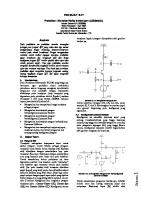
Gambar 5 Transistor NPN 4. Fungsi komponen Adapun prinsip kerja dari Transistor yakni : A. Saklar Elektronik Berikut gambar transistor yang dapat dianalisa sebagai saklar :
6
Gambar 6 Dari gambar analogi saklar tersebut, bila basis diberi sinyal maka saklar akan terdorong sehingga akan menutup, dengan demikian arus akanmengalir dar C ke E bila dalam rangkaian digambarkan sebagai berikut :
Gambar 7 Keterangan VR
= resistor variable = Lampu pijar
Tegangan positif akan masuk ke transistor yaotu ke kolektor melalui R1 dan ke basis melalui R2 dan VR (resistor variable) R3 berfungsi sebagai umpan negatif agar arus mesuk ke basis. Bila VBE telah tercapai, maka transistor akan di ‘on” sebagai saklar, sehingga arus akan mengalir dari kolektor ke emiter dan lampu akan menyala. B. Penguat Sinyal
7
Gambar 9 Penguatan sinyal pada transistor “bila kaki kolektor dan emiter diberi tegangan dan basis diberi sinyal input maka transistro akan ‘on’ sehingga arus mengalir dari C ke E. sinyal basis akan diperkuat oleh arus tersebut yang dapat dideteksi melalui output pada C dan E. ICB0 : arus bocor pada transistor yang mengalir dari kolektro kemudian ke basis, lalu ke netral Basis : Kaki transistor untuk memasukkan input sinyal yang akan diperkuat Keadaan jenuh : Suatu keadaan dimana apabila sinyal input diperbesar maka sinyal output tidak xakan naik lagi. 5. Kurva Karakteristik A. Kurva Kolektor Karakteristik kolektor yang terlihat dari pengamatan kurva kolektor dibawah ini merelasikan antara IC , VBE, dan IB sebagai sumber parameter. Dari kurva kolektor tersebut, tampak disana ada 4 daerah yaitu daerah aktif, daerah saturation (jenuh), daerah cuf-off (putus), dan daerah breakdown (dadal).
Gambar 10 Kurva Kolektor
Daerah Aktif
8
Daerah antara tegangan lutut (knee), VK dan tegangan dadal (breakdown), VBR serta diatas IB = ICO. Daerah aktif terjadi bila sambungan emitor diberi bias maju dan sambungan kolektor diberi bias balik. Pada daerah aktif arus kolektor sebanding dengan arus basis ( IC = IB).
Tabel 1 Daerah Saturation (Jenuh) Daerah dengan VCE lebih kecil dari tegangan lutut (VK). Daerah saturasi terjadi bila sambungan emitor dan basis sama-sama diberi bias maju. Pada daerah saturasi, arus kolektor (IC) tidak tergantung pada arus basis (IB).Daerah Saturation (Jenuh).
Tabel 2 Daerah Cut-Off (Putus) Daerah yang terletak di bawah IB = ICO. Daerah cut-off terjadi bila sambungan kolektor dan emitor sama-sama diberi bias balik. Pada daerah cut-off, IE = 0 ; IC =ICO = IB.ah Cut-Off (Putus).
Tabel 3 Daerah Breakdown (Dadal) Daerah yang terletak di atas batas tegangan maksimum kolektor-emitor (VCE) suatu transistor. VCE maksimum pada beberapa jeni transistor adalah berbeda-beda. Pada kurva kolektor diatas terlihat, daerah breakdown terjadi setelah
9
VCE transistor mencapai diatas ± 10 volt. Transistor tidak boleh bekerja pada daerah ini, karena transistor dapat menjadi rusak.Daerah Breakdown (Dadal) Keterangan: VK = tegangan lutut (knee) IB = Arus basis ICO = Arus cut-off VCE = Tegangan kolektor-emitor VCE(sat) = Tegangan kolektor-emitor pada daerah saturasi B. Kurva Basis Kurva karakteristik basis merelasikan antara arus basis (IB) dan tegangan basis-emitor (VBE) dengan tegangan kolektor-emitor (VCE) sebagai parameternya.
Gambar 11 Kurva Karakteristik Basis Kurva basis diatas dapat terlihat pada alat ukur yang bernama osiloskop dengan cara menghubung singkatkan kolektor-emitor (VCE = 0) dan emitor diberi bias maju. (Karakter basis adalah seperti karakter komponen diode) Dengan bertambahnya VCE pada VBE yang konstan (tetap), maka lebar daerah deplesi di sambungan kolektor bertambah dan mengakibatkan lebar basis efektif berkurang. Dengan berkurangnya lebar basis, maka arus basis (IB) rekombinasi juga berkurang. (VK (tegangan lutut) atau tegangan ambang/threshold, untuk transistor silikon = 0.5 sampai 0,6 volt, untuk transistor germanium = 0,1 sampai 0,2 volt. VBE (tegangan basis-emitor) di daerah aktif, untuk transistor
10
silikon = 0.7 volt, untuk transistor germanium = 0,2 volt. VBE transistor ideal, VBE = 0 volt) C. Kurva Beta Kurva beta menunjukkan bahwa nilai β akan berubah dengan dipengaruhi oleh suhu (T) dan arus kolektor (IC). Berikut karakteristiknya: • • •
Nilai β bertambah jika suhu (T) naik. Nilai β bertambah jika arus kolektor (IC) naik. Nilai β turun jika arus kolektor (IC) naik di luar nilai tertentu.
Gambar 12 Kurva Beta (β) 6. Contoh Komponen Transistor adalah salah satu komponen elektronika dengan berbagai kegunaan, diantaranya sebagai penguat, sirkuit pemutus, menstabilkan tegangan, memodulasi sebuah sinyal, sebagai penyambung, dan masih banyak fungsi yang lainnya, disini ada beberapa jenih komponen Transistor BJT. a. Fet Transistor FET adalah komponen Elektronika aktif yang menggunakan Medan Listrik untuk mengendalikan Konduktifitasnya. Field Effect Transistor (FET) dalam bahasa Indonesia disebut dengan Transistor Efek Medan.
11
Gambar 13 b. Transistor PNP PNP adalah transistor bipolar yang menggunakan arus listrik kecil dan tegangan negatif pada terminal Basis untuk mengendalikan aliran arus dan tegangan yang lebih besar dari Emitor ke Kolektor.
Gambar 14 c. Transistor NPN Transistor NPN adalah transistor bipolar yang menggunakan arus listrik kecil dan tegangan positif pada terminal Basis untuk mengendalikan aliran arus dan tegangan yang lebih besar dari Kolektor ke Emitor.
12
Gambar 15 d. Transistor Mosfeet Transistor Mosfeet adalah transistor yang menggunakan isolator biasanya menggunakan silicon dioksida atau si02 diantara gerbang gate dan kanalnya, Mosfeet ini juga terdiri dua jenis konfigurasi yaitu mosfeet depletion yang masing masing jenis mosfeet ini juga terbagi menjadi mosfeet kanal P-channel dan mosfeet kanala N-channel.
Gambar 16 e. Transistor SMD Sebuah Transistor SMD (surface mount device) adalah jenis transistor yang disolder langsung ke permukaan papan komponen komputer. Meskipun transistor dipasang dengan cara ini bisa lebih mudah pecah, papan yang memanfaatkan transistor SMD lebih murah dari pada yang lainya. Alternatif untuk Transistor SMD adalah transistor melalui lubang, yang melekat pada papan dengan lengan logam yang dimasukkan ke lubang
13
yang di bor di papan. Pengeboran lubang ini yang membuat teknologinya jadi lebih mahal dan memakan waktu daripada teknologi SMD.
Gambar 17
BAB III PENUTUP Perhitungan – perhitungan di atas banyak menggunakan aproksimasi dan penyederhanaan. Tergantung dari keperluannya, untuk perhitungan lebih rinci dapat juga dilakukan dengan tidak mengabaikan efek – efek baha seperti resistansi, tegangan jepit antar junction dan sebagainya.
14
REFERENSI Diakses dari trikuni-desain-sistem.blogspot.com, diakses di http://trikuenidesain-sistem.blogspot.com/2013/11/Pengenalan-Transistor-Bipolar.html , diakses pada 24 Maret 2022 Diakses dari sribd.com, diakses di https://www.scribd.com/doc/225005790/bjt , diakses pada 23 Maret 2022 Diakses dari robotics-university.com, diakses di https://www.roboticsuniversity.com/2014/09/karakter-transistor-bjt.html , diakses pada 26 Maret 2022 Diakses dari dosenpendidikan.co.id, diakses di https://www.dosenpendidikan.co.id/transistor-adalah/ , diakses pada 27 Maret 2022 Diakses dari teknikelektronika.com, diakses di https://teknikelektronika.com/pengertian-field-effect-transistor-fet-dan-jenisjenisnya/ , diakses pada 27 Maret 2022
15
Lampiran (Datasheet) 1. Fet Transistor (JFET Transistor : MMBF310LT1G)
MMBFU310LT1G JFET Transistor N−Channel www.onsemi.com
Features
2 SOURCE
• These Devices are Pb−Free, Halogen Free/BFR Free and are RoHS Compliant
3 GATE Rating
Symbol
Value
Unit
Drain−Source Voltage
VDS
25
Vdc
Gate−Source Voltage
VGS
25
Vdc
IG
10
mAdc
Gate Current
MAXIMUM RATINGS
1 DRAIN
3
SOT−23 (TO−236AB) CASE 318−08 STYLE 10
1 2
Stresses exceeding those listed in the Maximum Ratings table may damage the Total Device Dissipation FR−5 Board (Note 1)
PD
Junction and Storage Temperature
mW
MARKING DIAGRAM
1.8
TA = 25°C Derate above 25°C Thermal Resistance, Junction−to−Ambient
225
RJA
556
TJ, Tstg
−55 to +150
mW/°C device. If any of these limits are exceeded, device functionality °C/W should not be assumed, damage may occur and reliability may be °C affected.
M6C M 1
THERMAL CHARACTERISTICS 1. FR−5 = 1.0 0.75 0.062 in. M6C
=
Device Code M
= Date
Code* = Pb−Free Package (Note: Microdot may be in either location) *Date Code orientation and/or overbar may vary depending upon manufacturing location.
16
ORDERING INFORMATION Device MMBFU310LT1G
Shipping†
Package SOT−23 (Pb−Free)
3000 Tape & Reel
†For information on tape and reel specifications, including part orientation and tape sizes, please refer to our Tape and Reel Packaging Specifications Brochure, BRD8011/D.
© Semiconductor Components Industries, LLC, 1994
1
October, 2016 − Rev. 6
Publication Order Number: MMBFU310LT1/D
MMBFU310LT1G ELECTRICAL CHARACTERISTICS (TA = 25°C unless otherwise noted) Characteristic
Symbol
Min
Max
Unit
V(BR)GSS
−25
−
Vdc
Gate 1 Leakage Current − (VGS = −15 Vdc, VDS = 0)
IG1SS
−
−150
pA
Gate 2 Leakage Current − (VGS = −15 Vdc, VDS = 0, TA = 125°C)
IG2SS
−
−150
nAdc
VGS(off)
−2.5
−6.0
Vdc
IDSS
24
60
mAdc
VGS(f)
−
1.0
Vdc
Forward Transfer Admittance − (VDS = 10 Vdc, ID = 10 mAdc, f = 1.0 kHz)
|Yfs|
10
18
mmho
Output Admittance − (VDS = 10 Vdc, ID = 10 mAdc, f = 1.0 kHz)
|yos|
−
250
mhos
Input Capacitance − (VGS = −10 Vdc, VDS = 0 Vdc, f = 1.0 MHz)
Ciss
−
5.0
pF
Reverse Transfer Capacitance − (VGS = −10 Vdc, VDS = 0 Vdc, f = 1.0 MHz)
Crss
−
2.5
pF
OFF CHARACTERISTICS Gate−Source Breakdown Voltage − (IG = −1.0 Adc, VDS = 0)
Gate Source Cutoff Voltage − (VDS = 10 Vdc, ID = 1.0 nAdc) ON CHARACTERISTICS Zero−Gate−Voltage Drain Current − (VDS = 10 Vdc, VGS = 0) Gate−Source Forward Voltage − (IG = 10 mAdc, VDS = 0) SMALL−SIGNAL CHARACTERISTICS
Product parametric performance is indicated in the Electrical Characteristics for the listed test conditions, unless otherwise noted. Product performance may not be indicated by the Electrical Characteristics if operated under different conditions.
17
-5.0
-4.0
-3.0
-2.0
0
-1.0
5.0
ID - VGS, GATE-SOURCE VOLTAGE
4.0
3.0
2.0
1.0
VGS, GATE-SOURCE VOLTAGE (VOLTS)
(VOLTS) IDSS - VGS, GATE-SOURCE CUTOFF VOLTAGE (VOLTS)
Figure 1. Drain Current and Transfer Characteristics vs Gate−Source Voltage www.onsemi.com 2
MMBFU310LT1G
Figure 2. Forward Transconductance vs Gate−Source Voltage
18 0.01
0.1 0.2 0.3 0.5 1.0 2.0 3.0 5.010 20 30 50 100
VGS, GATE SOURCE VOLTAGE (VOLTS)
ID, DRAIN CURRENT (mA)
Figure 4. On Resistance and Junction Capacitance vs Gate−Source Voltage
Figure 3. Common−Source Output Admittance and Forward Transconductance vs Drain Current
|S21|, |S11| 0.85 0.45 30
|S12|, |S22| 0.060 1.00 S22
3.0 0.79 0.39
24
0.048 0.98 S21
VDS = 10 V ID = 10 mA TA = 25°C
2.4
VDS = 10 V ID = 10 mA TA = 25°C
0.73 0.33
Y11
18
1.8
0.036 0.96
0.67 0.27 Y21
12
0.024 0.94 S11
1.2 0.61 0.21
Y22
6.0
S12
0.6 0.55 0.15 100
Y12 0 100
200 300 500 700 1000 f, FREQUENCY (MHz)
21, 11 180° 50°
12, 22
- 20°
11, 12
87°
21, 22
- 20° 120°
0 11
- 20°
22
40°
- 40° 21
160°
0.90 200 300 500 700 1000 f, FREQUENCY (MHz)
Figure 6. Common−Gate S Parameter Magnitude vs Frequency
Figure 5. Common−Gate Y Parameter Magnitude vs Frequency
170°
0.012 0.92
86°
- 40° 100°
85°
- 60°
80°
-120° 84°
- 80°
60°
-100°
40°
-120°
20° 100
21
- 20°
22
- 60°
30°
- 80°
- 40°
-100° 150° 140° 130°
20°
12
-140°
11
10° 0° 100
VDS = 10 V ID = 10 mA TA = 25°C
-160° 83° -180°
-200° 82° 200 300 500 700 1000 f, FREQUENCY (MHz)
Figure 7. Common−Gate Y Parameter Phase−Angle vs Frequency 10
9.0 8.0
7.0
6.0
5.0
4.0 3.0
2.0
21 12
VDS = 10 V ID = 10 mA TA = 25°C
11
www.onsemi.co m 3
- 80°
-100° 200 300 500 700 1000 f, FREQUENCY (MHz)
Figure 8. S Parameter Phase−Angle vs Frequency
1.0 0
- 60°
19 PACKAGE DIMENSIONS
DATE 30 JAN 2018 NOTES: 1. DIMENSIONING AND TOLERANCING PER ASME Y14.5M, 1994. 2. CONTROLLING DIMENSION: MILLIMETERS. 3. MAXIMUM LEAD THICKNESS INCLUDES LEAD FINISH.MINIMUM LEAD THICKNESS IS THE MINIMUM THICKNESS OF THE BASE MATERIAL. 4. DIMENSIONS D AND E DO NOT INCLUDE MOLD FLASH,PROTRUSIONS, OR GATE BURRS. MILLIMETERS INCHES DIM A A1 b c D E e L L1 HE T
MIN 0.89 0.01 0.37 0.08 2.80 1.20 1.78 0.30 0.35 2.10 0°
NOM 1.00 0.06 0.44 0.14 2.90 1.30 1.90 0.43 0.54 2.40 −−−
MAX 1.11 0.10 0.50 0.20 3.04 1.40 2.04 0.55 0.69 2.64
MIN 0.035 0.000 0.015 0.003 0.110 0.047 0.070 0.012 0.014 0.083
10°
0°
NOM 0.039 0.002 0.017 0.006 0.114 0.051 0.075 0.017 0.021 0.094 −−−
MAX 0.044 0.004 0.020 0.008 0.120 0.055 0.080 0.022 0.027 0.104 10°
END VIEW
RECOMMENDED SOLDERING FOOTPRINT
3X
2.90
0.90
0.95
3X 0.80 PITCH DIMENSIONS: MILLIMETERS
2.
STYLE 6: PIN 1. BASE EMITTER 3. COLLECTOR STYLE 10: PIN 1. DRAIN 2. SOURCE 3. GATE
XXXM
2.
PIN 1.
STYLE 16: PIN 1. ANODE CATHODE 3.
1
CATHODE
XXX = Specific Device Code M = Date Code = Pb−Free Package
STYLE 22: RETURN 2. OUTPUT 3. INPUT STYLE 28: PIN 1. ANODE 2. ANODE 3. ANODE
*This information is generic. Please refer to device data sheet for actual part marking. Pb−Free indicator, “G” or microdot “ ”, may or may not be present.
GENERIC MARKING DIAGRAM* STYLE 1 THRU 5: CANCELLED
STYLE 9: PIN 1. ANODE 2. ANODE
3. CATHODE
STYLE 15: PIN 1. GATE 2. CATHODE
20 3. ANODE
STYLE 11: PIN 1. 2. NO CONNECTION 3. SOURCE ANODE 3. CATHODE STYLE 13: STYLE 14: PIN 1. SOURCE PIN 1. 2. CATHODE CATHODE 3. CATHODE−ANODE STYLE 12: PIN 1. 2. DRAIN 2. GATE 3. GATE 3. ANODE CATHODE 2. CATHODE STYLE 17: PIN 1. 3. ANODE NO STYLE 19: STYLE 20: CONNECTION PIN 1. CATHODE PIN 1. CATHODE 2. ANODE 2. ANODE 2. ANODE STYLE 18: PIN 1. 3. CATHODE 3. CATHODE−ANODE 3. NO GATE CONNECTION 2. CATHODE STYLE 23: PIN 1. 3. ANODE ANODE STYLE 25: STYLE 26: PIN 1. ANODE PIN 1. 2. ANODE CATHODE 3. CATHODE 2. CATHODE 2. ANODE STYLE 24: STYLE 8: PIN 1. 3. GATE 3. NO CONNECTION PIN 1. GATE ANODE 2. DRAIN
STYLE 21: PIN 1. GATE 2. SOURCE 3. DRAIN STYLE 27: PIN 1. CATHODE 2. CATHODE 3. CATHODE STYLE 7: PIN 1. EMITTER 2. BASE 3. COLLECT OR
DOCUMENT NUMBER: DESCRIPTION:
98ASB42226B SOT−23 (TO−236)
Electronic versions are uncontrolled except when accessed directly from the Document Repository. Printed versions are uncontrolled except when stamped “CONTROLLED COPY” in red.
PAGE 1 OF 1
ON Semiconductor and are trademarks of Semiconductor Components Industries, LLC dba ON Semiconductor or its subsidiaries in the United States and/or other countries. ON Semiconductor reserves the right to make changes without further notice to any products herein. ON Semiconductor makes no warranty, representation or guarantee regarding the suitability of its products for any particular purpose, nor does ON Semiconductor assume any liability arising out of the application or use of any product or circuit, and specifically disclaims any and all liability, including without limitation special, consequential or incidental damages. ON Semiconductor does not convey any license under its patent rights nor the rights of others. © Semiconductor Components Industries, LLC, 2019
www.onsemi.com
onsemi, , and other names, marks, and brands are registered and/or common law trademarks of Semiconductor Components Industries, LLC dba “onsemi” or its affiliates and/or subsidiaries in the United States and/or other countries. onsemi owns the rights to a number of patents, trademarks, copyrights, trade secrets, and other intellectual property. A listing of onsemi’s product/patent coverage may be accessed at www.onsemi.com/site/pdf/Patent−Marking.pdf. onsemi reserves the right to make changes at any time to any products or information herein, without notice. The information herein is provided “as−is” and onsemi makes no warranty, representation or guarantee regarding the accuracy of the information, product features, availability, functionality, or suitability of its products for any particular purpose, nor does onsemi assume any liability arising out of the application or use of any product or circuit, and specifically disclaims any and all liability, including without limitation special, consequential or incidental damages. Buyer is responsible for its products and applications using onsemi products, including compliance with all laws, regulations and safety requirements or standards, regardless of any support or applications information provided by onsemi. “Typical” parameters which may be provided in onsemi data sheets and/or specifications can and do vary in different applications and actual performance may vary over time. All operating parameters, including “Typicals” must be validated for each customer application by customer’s technical experts. onsemi does not convey any license under any of its intellectual property rights nor the rights of others. onsemi products are not designed, intended, or authorized for use as a critical component in life support systems or any FDA Class 3 medical devices or medical devices with a same or similar classification in a foreign jurisdiction or any devices intended for implantation in the human body. Should Buyer purchase or use onsemi products for any such unintended or unauthorized application, Buyer shall indemnify and hold onsemi and its officers, employees, subsidiaries, affiliates, and distributors harmless against all claims, costs, damages, and expenses, and reasonable attorney fees arising out of, directly or indirectly, any claim of personal injury or death associated with such unintended or unauthorized use, even if such claim alleges that onsemi was negligent regarding the design or manufacture of the part. onsemi is an Equal Opportunity/Affirmative Action Employer. This literature is subject to all applicable copyright laws and is not for resale in any manner.
PUBLICATION ORDERING INFORMATION
2N3903, 2N3904
LITERATURE FULFILLMENT: Email Requests to: [email protected] onsemi Website: www.onsemi.com
◊ TECHNICAL SUPPORT North American Technical Support: Voice Mail: 1 800−282−9855 Toll Free USA/Canada Phone: 011 421 33 790 2910
Europe, Middle East and Africa Technical Support: Phone: 00421 33 790 2910 For additional information, please contact your local Sales Representative
2. Transistor PNP (2N3906)
2N3906
®
SMALL SIGNAL PNP TRANSISTOR
ABSOLUTE MAXIMUM RATINGS Symbol VCBO
Parameter Collector-Base Voltage (IE = 0)
www.onsemi.com 1
Value
Unit
-60
V
2N3903, 2N3904
VCEO
Collector-Emitter Voltage (IB = 0)
-40
V
VEBO
Emitter-Base Voltage (IC = 0)
-6
V
Collector Current
-200
mA
Ptot
Total Dissipation at TC = 25 oC
625
mW
Tstg
Storage Temperature
IC
Tj
Max. Operating Junction Temperature
-65 to 150
o
150
o
C C
February 2003
2N3906 THERMAL DATA Rthj-amb • Thermal Resistance Junction-Ambient Thermal Resistance Junction-Case Rthj-Case •
Max Max
o
200 83.3
C/W o
C/W
ELECTRICAL CHARACTERISTICS (Tcase = 25 oC unless otherwise specified) Symbol
Parameter
Test Conditions
Min.
Typ.
Max.
Unit
ICEX
Collector Cut-off Current (VBE = 3 V)
VCE = -30 V
-50
nA
IBEX
Base Cut-off Current (VBE = 3 V)
VCE = -30 V
-50
nA
V(BR)CEO∗
Collector-Emitter Breakdown Voltage (IB = 0)
IC = -1 mA
-40
V
V(BR)CBO
Collector-Base Breakdown Voltage (IE = 0)
IC = -10 µA
-60
V
V(BR)EBO
Emitter-Base Breakdown Voltage (IC = 0)
IE = -10 µA
-6
V
VCE(sat)∗
Collector-Emitter Saturation Voltage
IC = -10 mA IC = -50 mA
IB = -1 mA IB = -5 mA
-0.25 -0.4
V V
VBE(sat)∗
Base-Emitter Saturation Voltage
IC = -10 mA IC = -50 mA
IB = -1 mA IB = -5 mA
-0.85 -0.95
V V
DC Current Gain
IC = -0.1 mA IC = -1 mA IC = -10 mA IC = -50 mA IC = -100 mA
VCE = -1 V VCE = -1 V VCE = -1 V VCE = -1 V VCE = -1 V
hFE∗
fT NF
CCBO
-0.65 60 80 100 60 30
300
Transition Frequency
IC = -10mA VCE = -20 V f = 100 MHz
Noise Figure
VCE = -5 V IC = -0.1 mA f = 10 Hz to 15.7 KHz RG = 1 KΩ
4
dB
Collector-Base Capacitance
IE = 0
6
pF
VCB = -5 V
www.onsemi.com 2
f = 100 KHz
250
MHz
2N3903, 2N3904
CEBO
Emitter-Base Capacitance
IC = 0
VEB = -0.5 V
td
Delay Time
IC = -10 mA VCC = -3V
tr
Rise Time
ts
Storage Time
tf
Fall Time
IC = -10 mA VCC = -3V
f = 100 KHz
25
pF
IB = -1 mA
IB1 = -IB2 = -1 mA
35
ns
35
ns
225
ns
72
ns
∗ Pulsed: Pulse duration = 300 µs, duty cycle ≤ 2 %
2/5
2N3906
TO-92 MECHANICAL DATA mm
inch
DIM. MIN.
TYP.
MAX.
MIN.
TYP.
MAX.
A
4.32
4.95
0.170
0.195
b
0.36
0.51
0.014
0.020
D
4.45
4.95
0.175
0.194
E
3.30
3.94
0.130
0.155
e
2.41
2.67
0.095
0.105
e1
1.14
1.40
0.045
0.055
L
12.70
15.49
0.500
0.609
www.onsemi.com 3
2N3903, 2N3904
R
2.16
2.41
0.085
0.094
S1
1.14
1.52
0.045
0.059
W
0.41
0.56
0.016
0.022
V
4 degree
6 degree
4 degree
6 degree
2N3906
TO-92 AMMOPACK SHIPMENT (Suffix"-AP") MECHANICAL DATA mm DIM.
MIN.
inch
TYP.
MAX.
MIN.
TYP.
MAX.
A1
4.80
0.189
T
3.80
0.150
T1
1.60
0.063
T2
2.30
0.091
d
0.48
0.019
www.onsemi.com 4
2N3903, 2N3904
P0
12.50
12.70
12.90
0.492
0.500
0.508
P2
5.65
6.35
7.05
0.222
0.250
0.278
F1,F2
2.44
2.54
2.94
0.096
0.100
0.116
delta H
-2.00
2.00
-0.079
W
17.50
18.00
19.00
0.689
0.709
0.748
W0
5.70
6.00
6.30
0.224
0.236
0.248
W1
8.50
9.00
9.25
0.335
0.354
0.364
W2
0.50
H
18.50
H0
15.50
16.00
H1 D0
0.079
0.020
20.50
0.728
16.50
0.610
0.807 0.630
25.00 3.80
4.00
4.20
0.650 0.984
0.150
0.157
0.165
t
0.90
0.035
L
11.00
0.433
I1
3.00
delta P
-1.00
0.118 1.00
-0.039
0.039
2N3906
www.onsemi.com 5
2N3903, 2N3904
Information furnished is believed to be accurate and reliable. However, STMicroelectronics assumes no responsibility for the consequences of use of such information nor for any infringement of patents or other rights of third parties which may result from its use. No license is granted by implication or otherwise under any patent or patent rights of STMicroelectronics. Specification mentioned in this publication are subject to change without notice. This publication supersedes and replaces all information previously supplied. STMicroelectronics products are not authorized for use as critical components in life support devices or systems without express written approval of STMicroelectronics. The ST logo is a trademark of STMicroelectronics © 2003 STMicroelectronics – Printed in Italy – All Rights Reserved STMicroelectronics GROUP OF COMPANIES Australia - Brazil - Canada - China - Finland - France - Germany - Hong Kong - India - Israel - Italy - Japan - Malaysia Malta - Morocco Singapore - Spain - Sweden - Switzerland - United Kingdom - United States. http://www.st.com
DATA SHEET www.onsemi.com
3. Transistor NPN
General Purpose Transistors NPN Silicon
2N3903, 2N3904 Features
• Pb−Free Packages are Available*
MAXIMUM RATINGS Rating
Symbol
Value
Unit
Collector−Emitter Voltage
VCEO
40
Vdc
Collector−Base Voltage
VCBO
60
Vdc
Emitter−Base Voltage
VEBO
6.0
Vdc
Collector Current − Continuous
IC
200
mAdc
Total Device Dissipation
PD 625 5.0
mW mW/°C
1.5 12
W mW/°C
@ TA = 25°C Derate above 25°C Total Device Dissipation @ TC = 25°C Derate above 25°C Operating and Storage Junction Temperature Range
PD
TJ, Tstg
−55 to +150
°C
THERMAL CHARACTERISTICS (Note 1) Characteristic
Symbol
Max
www.onsemi.com 6
Unit
2N3903, 2N3904
Thermal Resistance, Junction−to−Ambient
RJA
200
°C/W
Thermal Resistance, Junction−to−Case
RJC
83.3
°C/W
Stresses exceeding those listed in the Maximum Ratings table may damage the device. If any of these limits are exceeded, device functionality should not be assumed, damage may occur and reliability may be affected. 1. Indicates Data in addition to JEDEC Requirements.
*For additional information on our Pb−Free strategy and soldering details, please download the onsemi Soldering and Mounting Techniques Reference Manual, SOLDERRM/D. COLLECTOR 3 2 BASE 1 EMITTER
TO−92 CASE 29 STYLE 1 1
12
3 STRAIGHT LEAD BULK PACK
2
3 BENT LEAD TAPE & REEL AMMO PACK
MARKING DIAGRAMS 2N 390x YWW
x = 3 or 4 Y = Year WW = Work Week = Pb−Free Package (Note: Microdot may be in either location)
www.onsemi.com 7
2N3903, 2N3904
ORDERING INFORMATION See detailed ordering and shipping information in the package dimensions section on page 3 of this data sheet.
www.onsemi.com 8
2N3903, 2N3904 © Semiconductor Components Industries, LLC, 2012
August, 2021 − Rev. 9
1
Publication Order Number:
2N3903/D ELECTRICAL CHARACTERISTICS (TA = 25°C unless otherwise noted) Characteristic
Symbol
Min
Max
Unit
Collector−Emitter Breakdown Voltage (Note 2) (IC = 1.0 mAdc, IB = 0)
V(BR)CEO
40
−
Vdc
Collector−Base Breakdown Voltage (IC = 10 Adc, IE = 0)
V(BR)CBO
60
−
Vdc
Emitter−Base Breakdown Voltage (IE = 10 Adc, IC = 0)
V(BR)EBO
6.0
−
Vdc
IBL
−
50
nAdc
ICEX
−
50
nAdc
20 40 35 70 50 100 30 60 15 30
− − − − 150 300 − − − −
OFF CHARACTERISTICS
Base Cutoff Current (VCE = 30 Vdc, VEB = 3.0 Vdc) Collector Cutoff Current (VCE = 30 Vdc, VEB = 3.0 Vdc) ON CHARACTERISTICS DC Current Gain (Note 2) (IC = 0.1 mAdc, VCE = 1.0 Vdc)
−
hFE 2N3903 2N3904 2N3903 2N3904 2N3903 2N3904 2N3903 2N3904 2N3903 2N3904
(IC = 1.0 mAdc, VCE = 1.0 Vdc) (IC = 10 mAdc, VCE = 1.0 Vdc) (IC = 50 mAdc, VCE = 1.0 Vdc) (IC = 100 mAdc, VCE = 1.0 Vdc) Collector−Emitter Saturation Voltage (Note 2) (IC = 10 mAdc, IB = 1.0 mAdc) (IC = 50 mAdc, IB = 5.0 mAdc
VCE(sat)
Base−Emitter Saturation Voltage (Note 2) (IC = 10 mAdc, IB = 1.0 mAdc) (IC = 50 mAdc, IB = 5.0 mAdc)
VBE(sat)
Vdc − −
0.2 0.3 Vdc
0.65 −
0.85 0.95
SMALL−SIGNAL CHARACTERISTICS Current−Gain − Bandwidth Product (IC = 10 mAdc, VCE = 20 Vdc, f = 100 MHz)
fT 2N3903 2N3904
MHz 250 300
− −
Output Capacitance (VCB = 5.0 Vdc, IE = 0, f = 1.0 MHz)
Cobo
−
4.0
pF
Input Capacitance (VEB = 0.5 Vdc, IC = 0, f = 1.0 MHz)
Cibo
−
8.0
pF
Input Impedance (IC = 1.0 mAdc, VCE = 10 Vdc, f = 1.0 kHz)
hie 2N3903 2N3904
Voltage Feedback Ratio (IC = 1.0 mAdc, VCE = 10 Vdc, f = 1.0 kHz)
k 1.0 1.0
8.0 10 X 10−4
hre 2N3903 2N3904
Small−Signal Current Gain (IC = 1.0 mAdc, VCE = 10 Vdc, f = 1.0 kHz)
0.1 0.5
5.0 8.0 −
hfe 2N3903 2N3904
Output Admittance (IC = 1.0 mAdc, VCE = 10 Vdc, f = 1.0 kHz)
50 100
200 400
1.0
40
− −
6.0 5.0
td
−
35
ns
tr
−
35
ns
hoe
Noise Figure (IC = 100 Adc, VCE = 5.0 Vdc, RS = 1.0 k , f = 1.0 kHz)
NF 2N3903 2N3904
mhos dB
SWITCHING CHARACTERISTICS Delay Time Rise Time
(VCC = 3.0 Vdc, VBE = 0.5 Vdc, IC = 10 mAdc, IB1 = 1.0 mAdc)
www.onsemi.com 9
2N3903, 2N3904 Storage Time
2N3903 2N3904
(VCC = 3.0 Vdc, IC = 10 mAdc, IB1 = IB2 = 1.0 mAdc)
Fall Time
ts
− −
175 200
ns
tf
−
50
ns
2. Pulse Test: Pulse Width 300 s; Duty Cycle 2%.
ORDERING INFORMATION Package
Shipping†
2N3903RLRM
TO−92
2000 / Ammo Pack
2N3904
TO−92
5000 Units / Bulk
TO−92 (Pb−Free)
5000 Units / Bulk
TO−92
2000 / Tape & Reel
TO−92 (Pb−Free)
2000 / Tape & Reel
TO−92
2000 / Ammo Pack
TO−92 (Pb−Free)
2000 / Ammo Pack
TO−92
2000 / Ammo Pack
2N3904RLRPG
TO−92 (Pb−Free)
2000 / Ammo Pack
2N3904RL1G
TO−92 (Pb−Free)
2000 / Tape & Reel
TO−92
2000 / Ammo Pack
TO−92 (Pb−Free)
2000 / Ammo Pack
Device
2N3904G
2N3904RLRA 2N3904RLRAG
2N3904RLRM 2N3904RLRMG
2N3904RLRP
2N3904ZL1 2N3904ZL1G
†For information on tape and reel specifications, including part orientation and tape sizes, please refer to our Tape and Reel Packaging Specifications Brochure, BRD8011/D.
+3 V
DUTY CYCLE = 2% +10.9V
275 10 k
- 0.5 V < 1 ns
CS < 4 pF*
* Total shunt capacitance of test jig and connectors
www.onsemi.com 10
300 ns
2N3903, 2N3904 Figure 1. Delay and Rise Time Equivalent Test Circuit
+3 V t1 10 < t1 < 500 s DUTY CYCLE = 2%
+10.9V 275 10 k
0 CS < 4 pF*
1N916 - 9.1 V′
< 1 ns
* Total shunt capacitance of test jig and connectors
Figure 2. Storage and Fall Time Equivalent Test Circuit
TYPICAL TRANSIENT CHARACTERISTICS
1.0
2.0 3.0
5.0 7.0 10
20 30
50 70 100
200
1.0
IC, COLLECTOR CURRENT (mA)
2.0 3.0
5.0 7.0 10
20 30
50 70 100
IC, COLLECTOR CURRENT (mA)
www.onsemi.com 11
5 5 200
2N3903, 2N3904
Figure 5. Turn−On Time
Figure 6. Rise Time
5 5 1.0
2.0
3.0
5.0 7.0 10 20
30
50 70 100 200
1.0
2.0
3.0
5.0 7.0 10 20
30
50 70 100 200 IC, COLLECTOR CURRENT (mA) IC, COLLECTOR CURRENT (mA) Figure 7.
Storage Time Figure 8. Fall Time
TYPICAL AUDIO SMALL−SIGNAL CHARACTERISTICS NOISE FIGURE VARIATIONS
0 0.1
0.2
0.4
1.0
2.0
4.0
10
20
40
0 0.1
100
0.2
0.4
1.0
2.0
4.0
10
20
f, FREQUENCY (kHz)
RS, SOURCE RESISTANCE (k OHMS)
Figure 9.
Figure 10.
www.onsemi.com 12
40
100
2N3903, 2N3904
h PARAMETERS (VCE = 10 Vdc, f = 1.0 kHz, TA = 25°C) 300
100 50
200 20 10
100 70
5
50 2 30 0.1
0.2 0.3 0.5 1.0 2.0 3.0 5.0 IC, COLLECTOR CURRENT (mA)
1 0.1
10
0.2 0.3 0.5 1.0 2.0 3.0 5.0 IC, COLLECTOR CURRENT (mA) Figure 12. Output
Figure 11. Current Gain
10
Admittance 20
10
10
7.0 5.0
5.0 3.0 2.0
2.0
1.0
1.0
0.5
0.7 0.2 0.1
0.2 0.3
0.5
1.0
2.0 3.0
5.0
0.5 0.1
10
0.2 0.3
IC, COLLECTOR CURRENT (mA)
0.5
1.0
2.0 3.0
5.0
10
IC, COLLECTOR CURRENT (mA)
Figure 13. Input Impedance
Figure 14. Voltage Feedback Ratio
TYPICAL STATIC CHARACTERISTICS 2.0
°C TJ = +125
VCE = 1.0 V
+25°C
1.0
0.7 - 55°C
0.5 0.3 0.2
0.1 0.1
0.2
0.3
0.5
0.7
1.0
2.0
3.0
5.0
7.0
10
IC, COLLECTOR CURRENT (mA)
www.onsemi.com 13
20
30
50
70
100
200
2N3903, 2N3904
Figure 15. DC Current Gain 1.0 TJ = 25°C 0.8
IC = 1.0 mA
10 mA
30 mA
100mA
0.6
0.4
0.2 0 0.01
0.02
0.03
0.05
0.07 0.1
0.2
0.3
0.5
0.7
1.0
2.0
3.0
5.0
7.0
10
IB, BASE CURRENT (mA)
Figure 16. Collector Saturation Region 1.2
1.0
TJ = 25°C VBE(sat)@ C I /IB =10
1.0
°C +25°C TO +125
0.5 VC FOR V CE(sat)
0.8
°C - 55°C TO +25
0 VBE @ VCE =1.0 V
0.6
-0.5
0.4
-1.0
°C - 55°C TO +25 °C +25°C TO +125
VCE(sat)@ C I /IB =10 0.2 0 1.0
VB FOR V BE(sat)
-1.5 -2.0 2.0
5.0
10
20
50
100
200
0
IC, COLLECTOR CURRENT (mA) Figure 17. “ON”
Voltages IC, COLLECTOR CURRENT (mA)
Figure
18. Temperature Coefficients
www.onsemi.com 14
20
40
60
80
100 120 140
160 180 200
PACKAGE DIMENSIONS TO−92 (TO−226) CASE 29−11 ISSUE AM
SCALE 1:1
DATE 09 MAR 2007
1
12
2
3
3
1. DIMENSIONING AND TOLERANCING PER ANSI Y14.5M, 1982. 2. CONTROLLING DIMENSION: INCH. 3. CONTOUR OF PACKAGE BEYOND DIMENSION R IS UNCONTROLLED. 4. LEAD DIMENSION IS UNCONTROLLED IN P AND BEYOND DIMENSION K MINIMUM.
STRAIGHT LEAD BULK PACK
STRAIGHT LEAD BENT LEAD BULK PACK TAPE & REEL AMMO PACK
NOTES:
A
B
R P L SEATING PLANE
INCHES
K
D
XX G
J
H
V
C SECTION X−X
1
N
MIN
MAX
MIN
MAX
A
0.175
0.205
4.45
5.20
B
0.170
0.210
4.32
5.33
C
0.125
0.165
3.18
4.19
D
0.016
0.021
0.407
0.533
G
0.045
0.055
1.15
1.39
H
0.095
0.105
2.42
2.66
J
0.015
0.020
0.39
0.50
K
0.500
---
12.70
---
L
0.250
---
6.35
---
N
0.080
0.105
2.04
2.66
---
P
N
MILLIMETERS
DIM
0.100
---
2.54
R
0.115
---
2.93
---
V
0.135
---
3.43
---
NOTES:
A
R
B
1. DIMENSIONING AND TOLERANCING PER ASME Y14.5M, 1994. 2. CONTROLLING DIMENSION: MILLIMETERS. 3. CONTOUR OF PACKAGE BEYOND DIMENSION R IS UNCONTROLLED. 4. LEAD DIMENSION IS UNCONTROLLED IN P AND BEYOND DIMENSION K MINIMUM.
BENT LEAD TAPE & REEL AMMO PACK
P SEATING PLANE
K
MILLIMETERS
XX
DIM
MIN
MAX
A
4.45
5.20
B
4.32
5.33
C
3.18
4.19
D
0.40
0.54
G
2.40
2.80
J
0.39
0.50
K
12.70
---
N
2.04
2.66
G V 1
C N T
SECTION X−X
P
1.50
4.00
R
2.93
---
V
3.43
---
STYLES ON PAGE 2 DOCUMENT NUMBER: STATUS:
98ASB42022B ON SEMICONDUCTOR STANDARD
Electronic versions are uncontrolled except when accessed directly from the Document Repository. Printed versions are uncontrolled except when stamped “CONTROLLED COPY” in red.
NEW STANDARD: © Semiconductor Components Indus tries, LLC, 2002
October, 2002
DESCRIPTION:− Rev. 0
C ase Outline Number:
http://onsemi.com TO−92 (TO−226)
STYLE 1: PIN 1. EMITTER 2. BASE 3. COLLECTOR
STYLE 27: PIN 1. MT 2. SUBSTRATE 3. MT
STYLE 6: PIN 1. GATE 2. SOURCE & SUBSTRATE 3. DRAIN
STYLE 32: PIN 1. BASE 2. COLLECTOR 3. EMITTER
PAGE 3XXX
1
2. INPUT 3. OUTPUT STYLE 4:
1
OF
STYLE 15: PIN 1. ANODE 1 2. CATHODE 3. ANODE 2
PIN 1. CATHODE
STYLE 11: PIN 1. ANODE 2. CATHODE & ANODE 3. CATHODE
TO−92 (TO−226)
CASE 29−11 STYLE 3:
STYLE 21: PIN 1. COLLECTOR 2. EMITTER 3. BASE
8:
PIN 1. VCC 2. GROUND 2 3. OUTPUT STYLE 31: PIN 1. GATE 2. DRAIN 3. SOURCE STYLE 2: PIN 1. BASE 2. EMITTER 3.COLLECTOR STYLE 7: PIN 1. SOURCE 2. DRAIN 3. GATE STYLE 12: PIN 1.MAIN TERMINAL 1 2. GATE 3. MAIN TERMINAL 2 STYLE 17: PIN 1. COLLECTOR 2. BASE 3. EMITTER STYLE 22: PIN 1. SOURCE 2. GATE 3. DRAIN
DOCUMENT NUMBER: STATUS:
3. ANODE STYLE 9: PIN 1. BASE 1 2. EMITTER 3. BASE 2
STYLE 16: PIN 1. ANODE 2. GATE 3. CATHODE
STYLE 26:
2. CATHODE
PIN 1. ANODE 2. ANODE STYLECATHODE PIN 1. 2. 3.
DRAIN GATE SOURCE SUBSTRATE
ISSUE AM STYLE 13: PIN 1. ANODE 1 2. GATE 3. CATHODE 2 STYLE 18: PIN 1. ANODE 2. CATHODE 3. NOT CONNECTED STYLE 23: PIN 1. GATE 2. SOURCE 3. DRAIN STYLE 28: PIN 1. CATHODE 2. ANODE 3. GATE STYLE 33: PIN 1. RETURN
STYLE 14: PIN 1. EMITTER 2. COLLECTOR 3. BASE
STYLE 20: PIN 1.NOT CONNECTED 2. CATHODE 3. ANODE STYLE 25: PIN 1. MT 1 2. GATE 3. MT 2 STYLE 30: PIN 1. DRAIN 2. GATE 3. SOURCE STYLE 35: PIN 1. GATE 2. COLLECTOR 3. EMITTER
STYLE 19: PIN 1. GATE 2. ANODE & 3. CATHODE STYLE 24: PIN 1. EMITTER 2. COLLECTOR/A NODE 3. CATHODE STYLE 29: PIN 1. NOT CONNECTED 2. ANODE 3. CATHODE STYLE 34: PIN 1. INPUT 2. GROUND 3. LOGIC
DATE 09 MAR 2007 STYLE 5: PIN 1. DRAIN 2. SOURCE 3. GATE STYLE 10: PIN 1. CATHODE 2. GATE 3. ANODE
98ASB42022B ON SEMICONDUCTOR STANDARD
Electronic versions are uncontrolled except when accessed directly from the Document Repository. Printed versions are uncontrolled except when stamped “CONTROLLED COPY” in red.
NEW STANDARD: © Semiconductor Components Indus tries, LLC, 2002
October, 2002
DESCRIPTION:− Rev. 0
http://onsemi.com TO−92 (TO−226)
2
C ase Outline Number:
PAGE 3XXX
2
OF
DOCUMENT NUMBER: 98ASB42022B PAGE 3 OF 3
ISSUE AM
REVISION ADDED BENT−LEAD TAPE & REEL VERSION. REQ. BY J. SUPINA.
DATE 09 MAR 2007
ON Semiconductor and are registered trademarks of Semiconductor Components Industries, LLC (SCILLC). SCILLC reserves the right to make changes without further notice to any products herein. SCILLC makes no warranty, representation or guarantee regarding the suitability of its products for any particular purpose, nor does SCILLC assume any liability arising out of the application or use of any product or circuit, and specifically disclaims any and all liability, including without limitation special, consequential or incidental damages. “Typical” parameters which may be provided in SCILLC data sheets and/or specifications can and do vary in different applications and actual performance may vary over time. All operating parameters, including “Typicals” must be validated for each customer application by customer’s technical experts. SCILLC does not convey any license under its patent rights nor the rights of others. SCILLC products are not designed, intended, or authorized for use as components in systems intended for surgical implant into the body, or other applications intended to support or sustain life, or for any other application in which the failure of the SCILLC product could create a situation where personal injury or death may occur. Should Buyer purchase or use SCILLC products for any such unintended or unauthorized application, Buyer shall indemnify and hold SCILLC and its officers, employees, subsidiaries, affiliates, and distributors harmless against all claims, costs, damages, and expenses, and reasonable attorney fees arising out of, directly or indirectly, any claim of personal injury or death associated with such unintended or unauthorized use, even if such claim alleges that SCILLC was negligent regarding the design or manufacture of the part. SCILLC is an Equal Opportunity/Affirmative Action Employer. This literature is subject to all applicable copyright laws and is not for resale in any manner. © Semiconductor Components Industries, LLC, 2007
March, 2007 − Rev. 11AM
Case Outline Number: 29
onsemi, , and other names, marks, and brands are registered and/or common law trademarks of Semiconductor Components Industries, LLC dba “onsemi” or its affiliates and/or subsidiaries in the United States and/or other countries. onsemi owns the rights to a number of patents, trademarks, copyrights, trade secrets, and other intellectual property. A listing of onsemi’s product/patent coverage may be accessed at www.onsemi.com/site/pdf/Patent−Marking.pdf. onsemi reserves the right to make changes at any time to any products or information herein, without notice. The information herein is provided “as−is” and onsemi makes no warranty, representation or guarantee regarding the accuracy of the information, product features, availability, functionality, or suitability of its products for any particular purpose, nor does onsemi assume any liability arising out of the application or use of any product or circuit, and specifically disclaims any and all liability, including without limitation special, consequential or incidental damages. Buyer is responsible for its products and applications using onsemi products, including compliance with all laws, regulations and safety requirements or standards, regardless of any support or applications information provided by onsemi. “Typical” parameters which may be provided in onsemi data sheets and/or specifications can and do vary in different applications and actual performance may vary over time. All operating parameters, including “Typicals” must be validated for each customer application by customer’s technical experts. onsemi does not convey any license under any of its intellectual property rights nor the rights of others. onsemi products are not designed, intended, or authorized for use as a critical component in life support systems or any FDA Class 3 medical devices or medical devices with a same or similar classification in a foreign jurisdiction or any devices intended for implantation in the human body. Should Buyer purchase or use onsemi products for any such unintended or unauthorized application, Buyer shall indemnify and hold onsemi and its officers, employees, subsidiaries, affiliates, and distributors harmless against all claims, costs, damages, and expenses, and reasonable attorney fees arising out of, directly or indirectly, any claim of personal injury or death associated with such unintended or unauthorized use, even if such claim alleges that onsemi was negligent regarding the design or manufacture of the part. onsemi is an Equal Opportunity/Affirmative Action Employer. This literature is subject to all applicable copyright laws and is not for resale in any manner.
PUBLICATION ORDERING INFORMATION
TMP10N60A(G)/TMPF10N60A(G) LITERATURE FULFILLMENT: Email Requests to: [email protected] onsemi Website: www.onsemi.com
◊ TECHNICAL SUPPORT North American Technical Support: Voice Mail: 1 800−282−9855 Toll Free USA/Canada Phone: 011 421 33 790 2910
Europe, Middle East and Africa Technical Support: Phone: 00421 33 790 2910 For additional information, please contact your local Sales Representative
4. Transistor Mosfet
Features ▪ Low gate charge ▪ 100% avalanche tested ▪ Improved dv/dt capability ▪ RoHS compliant ▪ Halogen free package ▪ JEDEC Qualification
October 2012 : Rev0
www.trinnotech.com
1/56
TMP10N60A(G)/TMPF10N60A(G) N-channel MOSFET BVDSS
ID
RDS(on)
600V
10A
100
MH
2
dB
Min. Transition Frequency at f = 100MHz
fT
IC = 10mA; VCE = 5V Noise Figure at RS = 2kW IC = 200mA; VCE = 5V f = 1kHz; B = 200Hz
F
Typ.
Ratings (at TA = 25°C unless otherwise specified) Description
Symbol
Collector-Base Voltage (Open Emitter)
V
Collector-Emitter Voltage (VBE = 0)
V
Collector-Emitter Voltage (Open Base)
V
Emitter-Base Voltage (Open Collector)
V
BC847B
Units
CBO
50 CES
V
Collector Current (DC)
CEO
Max.
45 6
EBO
IC
100
mA
BC847B
Units
200
mA
Ratings (at TA = 25°C unless otherwise specified)
Description Collector Current (Peak Value)
October 2012 : Rev0
Symbol I
CM
Max.
www.trinnotech.com
10/56
TMP10N60A(G)/TMPF10N60A(G)
Emitter Current (Peak Value)
-IEM
I
Base Current (Peak Value) Total Power Dissipation upto Ta: 25°C
BM
250
Ptot
Storage Temperature
Tstg
mW
-
-55 to +150
Max.
150
=
500
K/W
15 5
nA µA
°C Junction Temperature
Tj
Thermal Resistance From Junction to Ambient
R
th (j-a)
Characteristics (Tj = 25°C unless otherwise specified)
Collector Cut off Current IE = 0; VCB = 30V IE = 0; VCB = 30V; Tj = 150°C
October 2012 : Rev0
< ICBO
www.trinnotech.com
11/56
TMP10N60A(G)/TMPF10N60A(G)
Base-Emitter Voltage IC = 2mA; VCE = 5V
VBE
IC = 10mA; VCE = 5V Saturation Voltage
VBE V
IC = 10mA; IB = 0.5mA
V
IC = 100mA; IB = 5mA
V
IE = Ie = 0; VCB = 10V
BE (sat)
CE (sat)
V Collector Capacitance at f = 1MHz
CE (sat)
CC
IC = 10mA; VCE = 5V
fT
Noise Figure at RS = 2KW IC = 200µA; VCE = 5V; f = 1kHz; B = 200Hz
F
DC Current Gain IC = 10mA; VCE = 5V
October 2012 : Rev0
100
MHz
Typ. Max.
2 10
dB
Typ. > Typ.