![Manual Mekanikal Mesin Terios 3sz Ve [PDF]](https://pdfs.asia/img/200x200/manual-mekanikal-mesin-terios-3sz-ve.jpg)
5 0 3 MB
EM TO INDEX
ENGINE MECHANICAL TIMING CHAIN ............................... EM–-0 2 COMPONENTS ......................... EM–-0 2 REMOVAL .................................. EM–-0 3 INSPECTION ............................. EM–-0 6 INSTALLATION .......................... EM–-0 7 CYLINDER HEAD ........................... EM–-012 COMPONENTS ......................... EM–-012 REMOVAL .................................. EM–-013 DISASSEMBLY .......................... EM–-016 INSPECTION ............................. EM–-017 ASSEMBLY ................................ EM–-022 INSTALLATION .......................... EM–-024 CYLINDER BLOCK ........................ EM–-032 COMPONENTS ......................... EM–-032 CYLINDER BLOCK (S221) ............ EM–32-1 COMPONENTS (S221) .............. EM–32-1 DISASSEMBLY .......................... EM–-033 INSPECTION ............................. EM–-040
ASSEMBLY ................................... EM–48 ENGINE TUNE-UP ............................. EM–56 ENGINE COOLANT ...................... EM–56 RADIATOR CAP ............................ EM–56 DRIVE BELT .................................. EM–56 ENGINE OIL ................................. EM–56 SPARK PLUG ................................ EM–56 VALVE CLEARANCE ..................... EM–56 IGNITION TIMING ........................ EM–56 BATTERY ...................................... EM–56 CHARCOAL CANISTER ............... EM–56 FUEL LINE & CONNECTION ........ EM–56 COMPRESSION CHECK .............. EM–56 CHECKING OF A/F (Air/Fuel) CONTROL SYSTEM .................. EM–58 SERVICE SPECIFICATIONS ............. EM–59 SSTs .................................................. EM–62 TIGHTENING TORQUE ..................... EM–63 JEM00001-00000
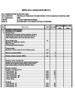
EM–2 TIMING CHAIN COMPONENTS w
B
: Tightening torque ★ : Non-reusable Unit : N·m
6.0 - 9.0
B B
B 5.3 - 9.8 q
e 7.2 - 10.8
B
N
B
B 8.8 - 13.2 r
@3
t★ 14.4 - 21.6 (M8 × 1.25) 7.5 - 10.8 (M6 × 1.0)
7.2 - 10.8 !3
5.3 - 9.8 !0
B
B
!1
@5
!2★ !4
5.9 - 11.1
B
B i
@4 @6
15.2 - 22.8
B
B @7
o
u y
@2
!5
@1 @8 B
B
B !9
8.1 - 13.8
@0
!7★ 120 - 140
!6
5.3 - 9.8
5.3 - 9.8 B !8 5.3 - 9.8
q w e r t y u i o !0 !1 !2 !3 !4
Oil filler cap Ignition coil Igniter assy Cylinder head cover Cylinder head cover gasket Water pump pulley Water pump Water pump gasket Timing chain cover No. 2 Oil control valve Timing chain cover Timing chain cover gasket Timing chain tensioner Tensioner arm
!5 !6 !7 !8 !9 @0 @1 @2 @3 @4 @5 @6 @7 @8
Timing chain Crankshaft pulley Type T oil seal Crank angle sensor Crank angle sensor plate Timing chain guide No. 2 Timing chain guide Valve timing controller Camshaft No. 1 Camshaft No. 2 sprocket Camshaft No. 2 Camshaft sprocket key Crankshaft JEM00002-00001
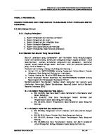
EM–3 REMOVAL 1. Remove the drive belt. (Refer to the CH section.) 2. Remove the ignitor assembly. (European specifications only)
JEM00003-00002
3. Remove the ignition coil from the cylinder head cover.
JEM00004-00003
4. Remove the cylinder head cover and gasket by removing the retaining bolts and nuts in the sequence shown in the right figure.
!2
y
w
!0
q
i
r
t
o
!1
!3
u
e JEM00005-00004
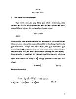
5. Remove the alternator bracket.
JEM00006-00005
6. Remove the oil control valve from the timing chain cover.
JEM00007-00006
EM–4 7. Remove the idler pulley bracket.
JEM00008-00007
8. Remove the crank angle sensor from the timing chain cover.
JEM00009-00008
9. Remove the water pump pulley. 10. Remove the idler pulley.
Water pump pulley
Idler pulley
JEM00010-00009
11. Turn the crankshaft in the engine rotating direction, until the timing mark on the crankshaft pulley is aligned with the indicator on the timing chain cover. NOTE: • At this point, the No. 1 cylinder assumes the top dead center.
JEM00011-00010
12. Ensure that the mate mark on the camshaft timing sprocket points upward. If the mate mark does not point upward, turn the crankshaft another one turn. And ensure that now the mark points upward. NOTE: • Now, the No. 1 cylinder assumes the top dead center under the compression stroke. Mate mark JEM00012-00011
EM–5 13. Remove the crankshaft pulley by removing the pulley bolt, while preventing the crankshaft pulley from being turned, using the following SST. SST: 09278-87201-000
JEM00013-00012
14. Removal of oil pan. (1) Loosen the attaching bolts and nuts of the oil pan over two or three stages. Pull out the bolts and nuts. (2) Separate the oil pan from the cylinder block by driving the following SST into between the cylinder block and the oil pan. SST: 09032-00100-000
JEM00230-00215
15. Remove the timing chain cover by removing the retaining bolts and nuts.
JEM00014-00013
16. Remove the crank angle sensor plate.
F
JEM00015-00014
17. Move the chain tensioner stopper plate downward. Under this unlocked state, push in the plunger deeply.
Stopper plate JEM00016-00015
EM–6 18. With the plunger in a pushed-in state, align the holes of the stopper plate and chain tensioner. Insert a hexagonal rod wrench into place to lock it. NOTE: • For this operation, use a hexagonal rod wrench whose width across flats is 2.5 mm.
JEM00017-00016
19. Remove the chain tensioner under a condition in which the plunger is locked with the hexagonal rod wrench inserted.
JEM00018-00017
20. Remove the timing chain by removing the timing chain guide No. 2. 21. Remove the crankshaft timing sprocket.
JEM00019-00018
22. Remove the timing chain guide and timing chain arm.
JEM00020-00019
INSPECTION Chain Guide and Chain Arm Measure the wear of the chain guide and arm. Allowable Wear Limit: 0.5 mm If the wear exceeds the allowable wear limit, replace the chain guide and/or chain arm. Wear
JEM00021-00020
EM–7 Chain Tensioner 1. Depress the stopper plate with your finger. Ensure that the plunger moves smoothly. 2. When your finger is released from the stopper plate, ensure that the stopper plate is locked. Under this state, the plunger will not move, even if the plunger is moved with your finger.
Move
Raise Lock
JEM00022-00021
INSTALLATION 1. Install the timing chain guide. Tightening Torque: 5.3 - 9.8 N·m
JEM00023-00022
2. Assemble the crankshaft timing sprocket. 3. Align the mate mark of the timing chain mark plate (golden color) with the mate mark of the crankshaft timing sprocket. Proceed to install the timing chain.
Golden color
Mate mark JEM00024-00023
4. Install the timing chain guide No. 2. Tightening Torque: 5.3 - 9.8 N·m NOTE: • After the timing chain guide No. 2 has been installed in place, the chain teeth of the crankshaft timing sprocket section will not jump up.
JEM00025-00024
5. Align the mate mark of the timing chain mark plate (golden color) with the mate mark of the camshaft timing sprocket. Proceed to install the timing chain.
Golden color
Mate mark JEM00026-00025
EM–8 6. Install the timing chain arm. Tightening Torque: 15.2 - 22.8 N·m
JEM00027-00026
7. Slightly turn the camshaft counterclockwise, using the hexagonal section of the camshaft so that the chain at the tensioner side may be slackened. Under this state, proceed to install the tensioner. Tightening Torque: 7.2 - 10.8 N·m
JEM00028-00027
8. Pull out the hexagonal rod wrench from the chain tensioner. NOTE: • Ensure that a tension is applied to the timing chain.
JEM00029-00028
9. Install the crank angle sensor plate in such a direction that the “F” mark comes at the front side.
F
JEM00030-00029
10. Assemble a new timing chain cover gasket on the timing chain cover.
JEM00031-00030
EM–9 11. Apply liquid gasket at those points shown in the figure below. Install the timing chain cover. Tightening Torque: 14.4 - 21.6 N·m (M8 × 1.25) 7.2 - 10.8 N·m (M6 × 1.0) Liquid Gasket: Three Bond TB 1280E or equivalent NOTE: • Make sure to completely remove all foreign substance and oil, etc. from the gasket surface. • The assembling should be carried out within three minutes after the application of liquid gasket.
: Application points of liquid gasket
C C
C C A
A B
3 ~ 4 mm
B
3 ~ 4 mm
A-A cross-section 03 ~ 4 mm B-B cross-section 03 mm C-C cross-section 06 mm
JEM00032-00031
12. Install the oil pan (For the installation procedure, refer to EM–53.) 13. Assemble the crankshaft pulley. Install the pulley bolt, using the following SST. SST: 09278-87201-000 Tightening Torque: 120 - 140 N·m
JEM00033-00032
14. Install the idler pulley. Tightening Torque:
35.2 - 52.8 N·m
15. Install the water pump pulley. Tightening Torque: 8.1 - 15.0 N·m
Water pump pulley
Idler pulley
JEM00034-00033
EM–10 16. Install the crank angle sensor. Tightening Torque: 5.3 - 9.8 N·m NOTE: • Prior to the installation, apply oil to the O-ring section of the sensor.
JEM00035-00034
17. Install the oil control valve. Tightening Torque: 5.3 - 9.8 N·m NOTE: • Be sure to completely remove any foreign matter that may lodge at the installation hole or oil control valve. • Apply engine oil to the O-ring section.
JEM00036-00035
18. Install the alternator bracket and idler pulley bracket.
JEM00037-00036
19. Set the cylinder head cover gasket to the gasket groove of the head cover. Insert the gasket into the boss at the central section. Insertion Amount: 1 to 7 mm
Gasket 1 - 7 mm
JEM00038-00037
EM–11 20. Apply liquid gasket to those points indicated in the right figure. Liquid Gasket: Three Bond TB 1280E or equivalent
Liquid gasket
NOTE: • Guide to application amount: 5 mm in diameter and 2 mm in height • The assembling should be carried out within three minutes after the application of liquid gasket. JEM00039-00038
21. Assemble the head cover retaining bolts in the sequence specified in the right figure. Tightening Torque: 7.2 - 10.8 N·m (Cap nut) 8.8 - 13.2 N·m (Nut) NOTE: • Before the two cap nuts are installed on the central section of the cylinder head cover, install the washer seal in place.
w
i
!2
r
!3
y
o
!0
t
e
q
u
!1 JEM00040-00039
22. Install the ignition coil. Tightening Torque:
6.0 - 9.0 N·m
JEM00041-00040
23. Install the ignitor assembly. (European specifications only) Tightening Torque: 5.3 - 9.8 N·m 24. Install the drive belt. (Refer to the CH section.)
JEM00042-00041
EM–12 CYLINDER HEAD COMPONENTS B : Tightening torque ★ : Non-reusable Unit : N·m
B
w
B B 14.4 - 21.6 e
r B
q t 15.2 - 22.8 B
!5
B
u
B
!6 !7 !8 !9★ @0
y★ i★ !0
o 10.5 - 14.5
!2
@1
!1
40 - 54
!4 6.4 - 9.6
17.1 - 31.9
B
B
42.3 - 47.7 @5
!3
@6 B
@2 @3
B
5.3 - 9.8
@4
B
@7 #0 @8★
B
B @9
B B
B B #1★
B
20 - 30
B 5.3 - 9.8
q w e r t y u i o !0 !1
Oil filler cap Ignition coil Spark plug Igniter assy Cylinder head cover Cylinder head cover gasket Intake manifold Intake manifold gasket Camshaft bearing cap No. 1 Camshaft bearing cap No. 2 Valve timing controller
!2 !3 !4 !5 !6 !7 !8 !9 @0 @1 @2 @3
Camshaft No. 1 Camshaft No. 2 sprocket Camshaft No. 2 Valve lifter Valve spring retainer lock Valve spring retainer Valve spring Valve stem oil seal Valve seat Valve Straight screw plug Gasket
@4 @5 @6 @7 @8 @9 #0
Oil control valve filter Valve guide Cam angle sensor Cylinder head Exhaust manifold gasket Exhaust manifold Exhaust manifold heat insulator #1 Cylinder head gasket
JEM00043-00042
EM–13 REMOVAL 1. Remove the timing chain. (Refer to the Timing Chain section.) 2. Remove the throttle body.
JEM00044-00043
3. Remove the throttle body bracket.
JEM00045-00044
4. Remove the oil level gauge and oil level gauge bracket. NOTE: • The oil level gauge bracket has been provided only on the J102 series.
JEM00046-00045
5. Remove the pulsation damper.
JEM00047-00046
6. Remove the fuel delivery pipes and injectors.
JEM00048-00047
EM–14 7. Remove the intake manifold.
JEM00049-00048
8. Remove the air valve pipe. (J102 series only) 9. Remove the DVVT oil filter.
JEM00050-00049
10. Remove the exhaust manifold cover.
JEM00051-00050
11. Remove the oxygen sensor.
JEM00052-00051
12. Remove the exhaust manifold and gasket.
JEM00053-00052
Revision 1
EM–15
13. Remove the cam angle sensor.
sEM00244-00218
14. Remove the radiator thermo control switch. (M101, J102 series) 15. Remove the water inlet. Remove the thermostat. (M101, J102 series) 16. Remove the engine coolant temperature sensor. (M101, J102 series)
sEM00245-00219
16-1. Remove the water outlet and thermostat. (S221 series) 16-2. Remove the water outlet housing and water inlet pipe subassembly. (S221 series)
sEM00057-00055
16-3. Remove the radiator thermo control switch. (S221 series) 16-4. Remove the engine coolant temperature sensor and water bypass outlet subassembly. (S221 series)
sEM00058-00056
17. Remove the spark plugs.
sEM00246-00220
EM–15-1
Revision 1
18. Remove the camshaft bolt, while preventing the camshaft No. 1 from turning, using the hexagonal section of the camshaft No. 1. Remove the DVVT controller from the camshaft No. 1.
sEM00247-00221
19. Turn the crankshaft 90 degrees in the engine rotating direction. NOTE: • When the camshaft is turned in the following Step (20), care must be exercised to ensure that the valves will not interfere with the piston.
sEM00248-00222
EM–16 20. Turn the cams, as indicated in the right figure, using the hexagonal sections of the camshafts No. 1 and No. 2. NOTE: • The cam should be turned to such a position where the valve lifter pushes up least the camshaft.
Camshaft No. 1 (IN side) No. 3
Camshaft No. 2 (EX side)
No. 4
No. 4
No. 2
JEM00059-00058
21. Remove the camshaft bearing caps No. 1 and No. 2 in the sequence specified in the right figure.
!0
o
!2
i
t
!1
w r e q
y
u JEM00060-00059
22. Remove the camshafts No. 1 and No. 2.
JEM00061-00060
23. Remove the cylinder head retaining bolts in the sequence specified in the right figure. Remove the cylinder head and gasket from the cylinder block.
e
t
!0
i
q
u
o
y
w
r JEM00062-00061
DISASSEMBLY Cylinder head 1. Remove the valve lifters from the cylinder head.
JEM00063-00062
EM–17 2. Remove the valve spring retainer locks, using the following SSTs. SST: 09202-87002-000 09202-87002-0A0
JEM00064-00063
3. 4. 5. 6.
Remove the valve spring retainers, and valve springs. Remove the valves from the cylinder head. Remove the valve stem oil seals, using pliers or the like. Remove the valve spring seats from the cylinder head. WARNING: • Make sure to protect your eyes with safety goggles during this operation. • Be very careful not to allow the spring, etc. to jump out.
JEM00065-00064
Camshaft No. 2 1. Secure the camshaft by clamping it in a vise. CAUTION: • Be very careful not to scratch the cam journal section. 2. Remove the camshaft drive gear from the camshaft.
JEM00066-00065
INSPECTION Cylinder head NOTE: • Clean the cylinder head by removing the remaining gasket materials, carbon deposits, and so forth. • Check the cylinder head for cracks, using a dye penetration or like. JEM00068-00000
EM–18 1. Check of cylinder head for flatness Using a precision straight edge and a feeler gauge, check the gasket surfaces contacting the cylinder head and manifolds for warpage. Maximum Surface Warpage: Cylinder Block Side: 0.04 mm Intake Manifold Side: 0.10 mm Exhaust Manifold Side: 0.05 mm If surface warpage of the cylinder block side exceeds the maximum limit, reface or replace the cylinder head. If surface warpage of the intake manifold and/or exhaust manifold side exceeds the maximum limit, replace the cylinder head. If the cylinder head surface warpage at the cylinder block side exceeds the maximum warpage, reface the cylinder head within the minimum thickness limit. Cylinder Head Height Limit: 112.7 mm
JEM00069-00067
2. Check of camshaft oil clearance NOTE: • Prior to this oil clearance check, the camshaft should be checked for bend in advance. (See page EM–20.) (1) Measure the oil clearance between the camshaft and the camshaft bearing cap. NOTE: • For the tightening method of the camshaft bearing cap, refer to page EM–25. Oil Clearance: IN: No. 1: 0.025 - 0.061 No. 2 ~ No. 5: 0.037 - 0.073 EX: No. 1 ~ No. 5: 0.037 - 0.073
JEM00070-00068
If the oil clearance does not conform to the specification, measure the camshaft journals, camshaft bearing cap bore diameter. Replace the any part which will not conform to the specifications. NOTE: • As for the replacement of the camshaft bearing cap, it should be replaced as a set with the cylinder head.
Intake side
Exhaust side
Camshaft journal outer diameter
Camshaft bearing cap bore diameter
No. 1
33.984 - 34.000
34.025 - 34.045
No. 2 - No. 5
22.979 - 22.995
23.032 - 23.052
No. 1
25.979 - 25.995
26.032 - 26.052
No. 2 - No. 5
22.979 - 22.995
23.032 - 23.052
JEM00071-00069
EM–19 3. Check of camshaft thrust clearance Assemble the camshaft, referring to the assembling procedure of the camshaft in EM–25. Measure the thrust clearance. Specified Thrust Clearance: Intake Side 0.10 - 0.24 mm Exhaust Side 0.10 - 0.24 mm
JEM00072-00070
4. Check and grinding of valves (1) Visually inspect the valve stem for seizure or damage. NOTE: • If seizure or damage is found, replace the valve and valve guide bush as a set. • However, this replacement should be performed only after the checks for the valve seat, valve stem and valve guide bush have been finished. • The valve guide bush hole must be used for refacing the valve seat. Hence, if the valve guide bush hole exhibits any roughness due to seizure, etc., rectify the hole with an adjustable reamer.
JEM00073-00071
(2) Visually inspect the valve head for melting or damage. If the valve head exhibits any melting or damage, replace the valve. If the roughness on the contact surface can be corrected, grind the valve seat contact surface with a valve refacer. (3) Grind the valves only enough to obtain a smooth contact surface with the valve seat. Valve Face Angle: 45.5°
JEM00074-00072
NOTE: • Make sure the valves are ground to the correct valve face angle. (4) Visually inspect the valve stem end for abnormal wear. If the valve stem end exhibits abnormal wear, correct the stem end with a valve refacer. However, this correction should be made within a limit of 0.2 mm from the standard length. [Reference] Intake Valve: 79.4 mm Exhaust Valve: 79.8 mm
JEM00075-00073
NOTE: • Be very careful not to allow the valve to be overheated during grinding. Standard Length: Intake Valve: 88.15 mm (Unleaded) 88.35 mm (Leaded) Exhaust Valve: 89.1 mm JEM00076-00074
EM–20
Revision 1
sEM00000-00223
(5) Inspect the valve head for its stock thickness. Minimum Stock Thickness: Intake Valve: 0.8 ± 0.2 mm (Unleaded) 1.0 ± 0.2 mm (Leaded) Exhaust Valve: 1.0 ± 0.2 mm If the stock thickness of the valve head is less than the minimum stock thickness, replace it with a new one.
sEM00250-00224
5. Refacing of valve seat NOTE: • Be sure to always check the valve contact position when refacing the seat. • Be sure to gradually reduce your force at the end of grinding so that no difference in height may be formed in the refacing surface.
sEM00092-00087
(1) Using a 45-degree cutter, perform grinding to a contact width slightly greater than the specified value. (2) Check the valve contact position. It is satisfactory if the contact position comes at the center of the valve face. If the contact position will not come at the center, perform grinding further, using a 45-degree cutter. (3) Grind the valve seat, using a 20-degree cutter or a 70degree cutter, so that the valve contact position comes at the center all around the circumference of the valve and the contacting width conforms to the specified value. (4) Carry out hand lapping, using compound.
70° 45° 20°
1.4 ± 0.5 mm sEM00093-00088
sEM00094-00089
EM–20-1
Revision 1
6. Check of clearance between valve guide bush and stem (1) Measure the inner diameter of the valve guide, using a caliper gauge, as well as the outer diameter of the valve stem, using a micrometer, respectively. (2) Determine the difference between the respective measured values and calculate the clearance. If the calculated clearance exceeds the allowable limit, replace the valve or bush. NOTE: • The measurement should be conducted at several points, as indicated in the figure on the right. Then, calculate the clearance at the maximum wear section. • Table showing specified values and allowable limit values
Measuring point
Valve guide bush measuring section sEM00087-00082
Measuring point
Check of valve guide bush-to-valve stem clearance Items
Specified value
Guide bush inner diameter (mm) Valve stem outer diameter (mm)
IN EX
Allowable limit
05.0
+0.022 +0.010
—
05.0
–0.010 –0.025
—
05.0
–0.020 –0.035
— sEM00088-00083
Clearance (mm)
IN
0.020 - 0.047
0.070
EX
0.030 - 0.057
0.080
7. Replacement of valve guide bush (1) Warm up the cylinder head to 80 to 100°C, using hot water or the like. (2) Drive out the valve guide bush from the combustion chamber side, using a suitable tool. NOTE: • Never reuse the bush that has been driven out once. (3) Drive a new valve guide bush into position, until the projection height becomes the specified value, using a suitable tool. NOTE: • Be very careful not to excessively drive the bush. Be sure to confirm the dimension during the operation. Specified Value of Projection Height: 14.5 ± 0.3 (Both intake side and exhaust side)
sEM00089-00084
sEM00090-00085
(4) Using an adjustable reamer, ream the valve guide bush to remove any burr or the like. NOTE: • This reaming should be made only enough to remove the burr or the like. (5) Check of oil clearance Ensure that the oil clearance meets the specifications.
sEM00251-00225
EM–20-2
Revision 1
8. Check of manifold Check the cylinder head attaching surface of the intake manifold and exhaust manifold for warpage, using a straight edge and a thickness gauge. Maximum Warpage: 0.7 mm
sEM00252-00226
Camshaft 1. Check of gear Visually inspect the teeth for wear. 2. Check of shaft (1) Checking camshaft for runout Support the camshaft at its both ends with V-shaped blocks. Set a dial gauge to the mid-point of the center journal section of the camshaft. Turn the camshaft one turn, making sure that the camshaft will not move in the axial direction. Take a reading on the dial gauge during the turning. Calculate the maximum runout, i.e. the difference between the maximum and minimum readings. Maximum Runout: 0.03 mm
sEM00253-00227
If the runout exceeds the maximum limit, replace the camshaft.
sEM00254-00228
EM–21 (2) Checking of cam lobe height Measure the cam lobe height, using a micrometer. Specified Cam Lobe Height: K3-VE
K3-VE2
IN
40.45 mm
40.75 mm
EX
39.96 mm
40.69 mm
JEM00080-00080
3. Check of DVVT controller (1) Clamp the hexagonal section for servicing of the camshaft assembly No. 1 in a vice, etc. (2) Temporarily tighten the attaching bolt at the DVVT controller attaching bolt hole so as to plug the oil passage at the timing advance side.
JEM00231-00216
(3) Wind a vinyl tape, as indicated in the right figure. Then, make a hole at either of the two advance ports.
Advance port
JEM00232-00217
(4) Apply compressed air to the advance port where the hole has been made, using a pneumatic tool. CAUTION: • Care must be exercised, for oil will splash. NOTE: • The most retarded angle lock will be unlocked.
JEM00233-00218
(5) At this time, ensure that the most retarded angle lock of the DVVT controller becomes unlocked and the DVVT controller can be moved by your hand without binding within a range of approximately 30°. NOTE: • The DVVT controller will be locked when it comes to the most retarded angle position.
JEM00234-00219
EM–22 (6) After completion of the check, lock the DVVT controller at the most retarded angle position. Then, remove the timing pulley attaching bolt. NOTE: • After the bolt has been removed, be sure to wipe off any residual sealing material lodged at the screw hole of the camshaft. (Failure to perform this operation may result in malfunction of the DVVT after assembling.) JEM00235-00000
Thermostat For checking and replacement procedures, refer to the CO section. Radiator thermo control switch For checking procedure, refer to the CO section. Crank angle sensor For checking and replacement procedures, refer to the IG section. Cam angle sensor For checking and replacement procedures, refer to the IG section. Spark plug For checking and replacement procedures, refer to the IG section. JEM00082-00000
ASSEMBLY Cylinder head NOTE: • Thoroughly clean all parts to be assembled. • Before installing the parts, apply new engine oil to all sliding and rotating surfaces. • Replace all gaskets and oil seals with new ones. CAUTION: • It should be noted that the valves for unleaded gasoline specifications differ from those for leaded gasoline specifications. Identification marks: Unleaded Gasoline: IN=I1, EX=E1 Leaded Gasoline: IN=I9, EX=E9
Unleaded gasoline Exhaust valve
E
1
Leaded gasoline
Intake valve
I
1
Exhaust valve
E
9
Intake valve
I
9
JEM00083-00082
EM–23 1. Install the valve spring seat 2. Installation of valve stem oil seal (1) Apply engine oil to the inner surface of the metal ring of the stem oil seal. (2) Drive the valve stem oil seal into position. NOTE: • Make sure that the stem oil seals will not tilt against the stem.
15.8
JEM00084-00083
3. Dip the long portion of the valve stem end at least 20 mm into engine oil. 4. Install the valve to the cylinder head. NOTE: • Care must be exercised as to the installing position. Do not pull out the valve once it has been inserted. • If the inserted valve should be pulled out, replace the valve stem oil seal with a new one.
At least 20 mm
Dip this portion into engine oil.
JEM00085-00084
5. Assembly of valve springs, valve spring retainers and valve spring retainer locks (1) Install the valve spring to the valve lifter inserting hole. (2) Install the valve spring retainer to the valve spring. Install the valve spring retainer locks while compressing the valve spring retainer, using the following SST. SST: 09202-87002-000 09202-87002-0A0
JEM00086-00085
(3) After installing the valve spring retainer lock, lightly tap the valve spring retainer with a plastic hammer or the like so as to ensure that the valve spring retainer locks are installed securely. WARNING: • During this operation, care must be exercised to ensure that the valve spring retainer or retainer locks may not jump out. • Protect your eyes with safety goggles during this operation. • Never tap the hole into which the valve lifter is inserted.
JEM00087-00086
Camshaft No. 2 1. Secure the camshaft by clamping it in a vise. CAUTION: • Be very careful not to scratch the cam journal section. 2. Install the camshaft drive gear to the camshaft.
JEM00088-00087
EM–24 INSTALLATION 1. Clean the gasket attaching surfaces of the cylinder block and cylinder head with a scraper. Remove all foreign substance and oil, etc. completely from the gasket surface. NOTE: • Be very careful not to drop scrapping debris of the gasket into the holes of the water jacket and oil holes.
JEM00089-00088
Cylinder head Cylinder head gasket Liquid gasket Cylinder block Application points of liquid gasket Approx. 2.5 mm
; ;;; ;
2. Apply liquid gasket, following the procedure shown in the right figure. Set the cylinder head gasket and cylinder head. Liquid Gasket: Three Bond TB 1280E or equivalent
NOTE: • The assembling should be carried out within three minutes after the application of liquid gasket. • Care must be exercised to ensure that no valve lifter may drop from the cylinder head.
IN side
EX side
20 ± 3 mm 18 ± 3mm
6 mm
2 mm
JEM00090-00089
3. Install the plate washer on each cylinder head bolt. Apply engine oil to the threaded portion of each bolt and the seat surface of each plate washer. NOTE: The washer plate can be installed in either way. The washer does not have the front side nor the back side.
Application of engine oil
JEM00091-00090
4. Tighten the cylinder head over two to three stages in the sequence specified in the right figure. Tightening Torque: 32.0 - 34.0 N·m
i
y
q
e
!0
r
w
t
o
u JEM00092-00091
5. Put a paint mark on the head section of each bolt at the engine front side. 6. Tighten the attaching bolts further 90 degrees, using the mark as a guide.
Paint mark Tighten further 90 degrees.
JEM00093-00092
EM–25 NOTE: • Using a micrometer, measure the diameter of the shaded, threaded ridge portion of the cylinder head bolt, as indicated in the right figure. This measurement should be conducted at several points. If the diameter has worn exceeding the allowable limit, replace the cylinder head bolt. Allowable Limit: Diameter of threaded ridge diameter:
25
20
8.75 mm JEM00094-00093
7. Turn the crankshaft 90 degrees in the engine rotating direction from the top dead center of No. 1 cylinder. NOTE: • Utmost attention must be paid so that a lifting valve will not interfere with the piston when assembling the camshaft.
JEM00095-00094
8. Apply engine oil to the cam lobe sections of the camshafts No. 1 and No. 2, the cylinder head journal sections and the top sections of the lifters.
JEM00096-00095
9. With the cam position aligned as shown in the right figure, set the camshaft to the cylinder head.
Camshaft No. 1 (IN side) No. 3
Camshaft No. 2 (EX side)
No. 4
No. 4
No. 2
JEM00097-00096
10. Install the camshaft bearing caps No. 1 and No. 2 in the sequence specified in the right figure. Tightening Torque: 10.5 - 14.5 N·m
e
r
u
t
q
w
!1 o
NOTE: • Make sure that the camshaft bearing cap is assembled in such a direction that the arrow-headed mark points toward the front of the engine.
!0 !2
i
y JEM00098-00097
EM–26 11. Insert the knocking pin at the forward end of the camshaft No. 1 into the knocking pin hole of the DVVT controller. Proceed to assemble the DVVT controller. NOTE: • After completion of the insertion, lightly turn the DVVT controller by your hand. Ensure that the knocking pin has been inserted securely in place.
Revision 1
Pin
sEM00255-000229
12. Tighten the camshaft bolt, while preventing the camshaft No. 1 from turning, using the hexagonal section of the intake camshaft. Tightening Torque: 40 - 54 N·m
sEM00256-000230
13. Install the spark plugs. Tightening Torque: 14.4 - 21.6 N·m
sEM00257-000231
14. With the jiggle pin of the thermostat aligned with the protruded section for locating the water inlet, install the water inlet in the cylinder head. (M101, J102 series) Tightening Torque: 7.2 - 10.8 N·m
sEM00258-000232
15. Install the radiator thermo control switch to the water inlet. (M101, J102 series) Tightening Torque: 30 - 40 N·m 16. Install the engine coolant temperature sensor. (M101, J102 series) Tightening Torque: 16 - 24 N·m
sEM00259-000233
EM–27
Revision 1
16-1. Assemble the water outlet, while facing the jiggle pin of the thermostat upward. (S221 series) Tightening Torque: 11.2 - 16.8 N·m
Projected section Cut-out section
Jiggle pin
sEM00115-00109
16-2. Install the engine coolant temperature sensor and water bypass outlet. (S221 series) Tightening Torque: 16 - 24 N·m 16-3. Install the radiator thermo control switch. (S221 series) Tightening Torque: 19.6 - 29.4 N·m
sEM00116-00110
17. Install the cam angle sensor to the cylinder head. Tightening Torque: 5.3 - 9.8 N·m NOTE: • Prior to the installation of the sensor, be sure to apply oil to the O-ring of the sensor.
sEM00260-00234
18. Install the exhaust manifold and gasket in the sequence specified in the right figure. (M101, J102 series) Tightening Torque: 21 - 29 N·m
e
w
r t
q
sEM00261-00235
19. Install the exhaust manifold and gasket in the sequence specified in the right figure. (S221 series) Tightening Torque: 23.2 - 34.8 N·m (Bolt) 32.0 - 48.0 N·m (Nut) r y
w
e q
t u
sEM00294-00262
EM–27-1
Revision 1
20. Install the oxygen sensor to the exhaust manifold. Tightening Torque: 29.0 - 39.0 N·m NOTE: • Never use an impact wrench when assembling the oxygen sensor. • Care must be exercised not to give damage to the harness during the assembling operation.
sEM00262-00236
21. Install the exhaust manifold cover. (M101, J102 series) Tightening Torque: 5.3 - 9.8 N·m
sEM00263-00237
22. Install the DVVT oil filter, using a new gasket. Tightening Torque: 17.1 - 31.9 N·m NOTE: • Make sure that no foreign substance gets to the filter hole and filter plug of the cylinder head. • The gasket is a non-resuable part. Install the air valve pipe. (J102 series only) sEM00264-00238
EM–28 23. Install the intake manifold. Tightening Torque: 15.2 - 22.8 N·m
JEM00110-00109
24. Install the fuel delivery pipes and injectors. Tightening Torque: 16.8 - 25.2 N·m
JEM00111-00110
25. Install the pulsation damper.
JEM00112-00111
26. Install the oil level gauge and insert the oil level gauge in place. Tightening Torque: 6.0 - 11.1 N·m
JEM00113-00112
27. Install the throttle body bracket. Tightening Torque: 16.8 - 25.2 N·m 28. Install the throttle body. Tightening Torque: 5.3 - 9.8 N·m 29. Install the timing chain. (Refer to the Timing Chain section.)
JEM00114-00113
EM–29 30. Adjustment of valve clearance (1) Turn the crankshaft in the engine rotating direction so that the crankshaft key groove may point upward. NOTE: • Set the No. 1 cylinder to the top dead center. JEM00115-00000
(2) Ensure that the mate mark on the camshaft timing sprocket points upward. If the mate mark does not point upward, turn the crankshaft another one turn. And ensure that now the mark points upward. NOTE: • Now, the No. 1 cylinder assumes the top dead center under the compression stroke. Mate marks
JEM00116-00115
(3) Check the valve clearances at those points specified in the right figure, using a thickness gauge. Valves to be checked at top dead center of No. 1 cylinder under compression stroke No. 1 cylinder IN
EX
No. 2 cylinder IN
No. 3 cylinder
EX
IN
—
—
EX
No. 4 cylinder IN
EX
—
— JEM00117-00116
(4) Turn the crankshaft another one turn so that the No. 1 cylinder assumes the top dead center under the exhaust stroke. Check the valve clearances at those points specified in the right figure. Valves to be checked at top dead center of No. 1 cylinder under exhaust stroke No. 1 cylinder
No. 2 cylinder
IN
EX
IN
—
—
—
EX
No. 3 cylinder IN
EX —
No. 4 cylinder IN
EX JEM00118-00117
EM–30 (5) If the valve clearances will not come within the specified values, remove the timing chain and camshaft. Specified Valve Clearances: Intake (cold): 0.145 - 0.235 Exhaust (cold): 0.275 - 0.365 (6) Select proper valve lifters, using the formula given below, so that the valve clearances may fall within the specified values. Intake (Thickness of lifter to be selected) = (Thickness of removed lifter) + [(Measured clearance) – 0.18 mm] Exhaust (Thickness of lifter to be selected) = (Thickness of removed lifter) + [(Measured clearance) – 0.31 mm] JEM00119-00000
NOTE: • The thickness of the lifter to be assembled must be measured at the center of the lifter. • Each valve lifter bears a mark that identifies its lifter thickness.
Viewed from direction A 16
Viewed from direction A JEM00120-00119
Code
Lifter thickness (mm)
Code
Lifter thickness (mm)
Code
Lifter thickness (mm)
Code
Lifter thickness (mm)
12
5.120
28
5.280
42
5.420
56
5.560
14
5.140
30
5.300
44
5.440
58
5.580
16
5.160
32
5.320
46
5.460
60
5.600
18
5.180
34
5.340
48
5.480
62
5.620
20
5.200
36
5.360
50
5.500
64
5.640
22
5.220
38
5.380
52
5.520
66
5.660
24
5.240
40
5.400
54
5.540
68
5.680
26
5.260 JEM00121-00000
EM–31 (7) Apply engine oil to the outer periphery of each selected valve lifter. Proceed to insert the valve lifters into the lifter holes. Assemble the camshafts No. 1 and No. 2. (Refer to EM–25.) (8) Install the timing chain and chain cover. (Refer to the Timing Chain section.) (9) Install the cylinder head cover and gasket on the cylinder head. (Refer to the Timing Chain section.) JEM00122-00000
EM–32 CYLINDER BLOCK COMPONENTS : Tightening torque ★ : Non-reusable parts Unit : N·m
q★
6.8 - 10.2 B
w
i
e B
u y
r
5.3 - 9.7 t
B
B 7.2 - 11.7
B o
!2 !3 !4
B
5.3 - 9.7 !0
B B !5
7.2 - 10.8 !6
!1
35.0 - 45.0
@1
!7 !8
@2
6.0 - 11.0
@0
@3
19.5 - 24.5 @7
@6 !9 @5 @4
@8 ★ B 120 - 140 @9 53.0 - 65.0
#0 6.0 - 11.0 B #1 #3
#2★ q w e r t y u i o !0 !1 !2 !3 !4 !5 !6 !7 !8 !9 @0
Cylinder head gasket Cylinder block Rear oil seal retainer Rear oil seal Rear end plate Water pump pulley Water pump Water pump gasket Timing chain oil nozzle Oil pump Oil relief valve Piston ring No. 1 Piston ring No. 2 Oil ring Piston pin Piston Connecting rod Connecting rod bearing Connecting rod cap Oil filter bracket
B ★
★
★
23.6 - 35.4 @1 Oil filter @2 Crankshaft pulley @3 Crankshaft angle sensor plate @4 Crankshaft sprocket @5 Key @6 Crankshaft thrust washer
6.0 - 11.0 (M6 × 1.0) 29.4 - 54.6 (M10 × 1.25) @7 @8 @9 #0 #1 #2 #3
Crankshaft Crankshaft bearing Crankshaft bearing cap Baffle plate Oil strainer O ring Oil pan JEM00124-00122
EM–32-1
Revision 1
CYLINDER BLOCK (S221) COMPONENTS (S221) S221 series : Tightening torque ★ : Non-reusable parts Unit : N·m u y B
q★ w
i
6.8 - 10.2 B e B
r
5.3 - 9.7 t
B 7.2 - 10.8
@0 B o
!2 !3 !4
B
5.3 - 9.7 !0
!5
7.2 - 10.8 !6
!1
35.0 - 45.0
19.5 - 24.5
!7 !8 @5
@1
@2
!9 @4 @3 @7
120.0 - 140.0
q w e r t y u i o !0 !1 !2 !3 !4 !5 !6 !7 !8 !9 @0 @1 @2 @3 @4 @5 @6 @7 @8 @9 #0 #1 #2
Cylinder head gasket Cylinder block Rear oil seal retainer Rear oil seal Rear end plate Water pump pulley Water pump Water pump gasket Timing chain oil nozzle Oil pump Oil relief valve Piston ring No. 1 Piston ring No. 2 Oil ring Piston pin Piston Connecting rod Connecting rod bearing Connecting rod cap Oil filter Crankshaft pulley Crankshaft angle sensor plate Crankshaft sprocket Key Crankshaft thrust washer Crankshaft Crankshaft bearing Crankshaft bearing cap Baffle plate Oil strainer Oil pan No. 2 Oil pan No. 1
@6
29.4 - 54.6 @8
B
B
29.4 - 44.1
53.0 - 65.0 6.0 - 11.0
B N B
6.0 - 11.0
@9
#2
#0 B 6.0 - 11.0
N
B
6.8 - 10.2
#1 B 6.8 - 10.2 sEM00138-00127
Revision 1
EM–33
DISASSEMBLY 1. Drain the engine oil by removing the drain plug of the oil pan. 2. Remove the timing chain. (For the removal procedure, refer to the Timing Chain section.) 3. Remove the cylinder head. (For removal procedure, refer to the Cylinder Head section.) 4. Drain the engine coolant by slackening the water drain cock. Remove the water drain cock. sEM00265-00239
5. Remove the oil pressure switch. 6. Remove the knock sensor. (Except European specifications)
sEM00266-00240
7. Remove the oil filter bracket. (M101, J102 series)
sEM00267-00241
Remove the oil filter. (S221 series) K3
7-1.
sEM00141-00130
8. Remove the oil pump and chain oil nozzle.
sEM00268-00242
EM–33-1
Revision 1
9. Remove the water pump and gasket.
sEM00269-00243
EM–34
Revision 2
10. Remove the oil strainer. (M101, M201 series) NOTE: • On the J102 series, the oil strainer is provided on the oil pan.
YEM00236-00220
11. Remove the clutch cover and clutch disc. NOTE: • Prevent the clutch cover from turning, using the following SST. SST: 09210-87701-000
YEM00130-00128
12. Check of flywheel (drive plate) runout. NOTE: • If the runout does not conform to the specification, confirm the tightening torque of the tightening torque conforms to the specified value, replace the flywheel (drive plate). Specified Runout Limit: Less than 0.2 mm
YEM00131-00129
13. Loosen the attaching bolts of the flywheel (drive plate) in the sequence as indicated in the right figure. Remove the flywheel (drive plate). y r
q
w
e t
YEM00132-00130
14. Remove the rear end plate.
YEM00133-00131
EM–35 15. Remove the rear oil seal retainer from the cylinder block.
JEM00137-00135
16. Measurement of connecting rod thrust clearance Measure the thrust clearance between the connecting rod and the crankshaft, using a thickness gauge. Thrust Clearance: Specified Value: 0.10 - 0.30 mm Maximum Limit: 0.35 mm NOTE: • The thrust clearance should be measured while the connecting rod is being pushed against either side of the crankshaft in the axial direction. Measure the thrust clearance at the opposite side.
JEM00138-00136
If the clearance exceeds the specified value, replace the connecting rod or the crankshaft, or both of them, referring to the width of the big end of the connecting rod in the thrust direction and the side width of the crankpin.
[Reference] Width of big end of connecting rod in thrust direction
Side width of crankpin
17.79 - 17.84 mm
17.94 - 18.09 mm
Connecting rod
Crankshaft
JEM00139-00137
EM–36 17. Loosen the connecting rod bearing cap bolts evenly over two or three stages. Then, remove the bolt. 18. Remove the connecting rod bearing cap.
JEM00140-00138
19. Measure the oil clearance between the crankpin and the connecting rod bearing cap. (For the tightening method of the connecting rod cap bolts, refer to page EM–51.) Oil Clearance: STD: 0.016 - 0.040 mm Maximum Limit: 0.07 mm NOTE: • If the oil clearance does not conform to the specification, measure the crankpin diameter, connecting rod big end bore diameter and connecting rod bearing center thickness, following the procedure given below. Replace any part which will not conform to the specifications.
JEM00141-00139
Measurement of crankpin diameter q Measure the crankpin diameter of the crankshaft in four directions for each crankshaft pin, 90 degrees spaced, at those points indicated in the right figure. w The greatest value among the measured diameters is regarded as the crankpin diameter. Specified Crankpin Diameter: 39.992 - 40.000 mm 4
12 4
12
JEM00142-00140
Measurement of connecting rod big end bore diameter q Perform measurement at the two points indicated in the figure. w The smaller value among the measured diameters is regarded as the connecting rod big end bore diameter. Specified Connecting Rod Big End Bore: 43.000 - 43.008 mm
A
B
4
4
JEM00143-00141
EM–37
Revision 1
Measurement of connecting rod bearing center thickness q Measure the connecting rod bearing center thickness. Connecting Rod Bearing Center Thickness: 1.488 - 1.492 mm sEM00270-00000
CAUTION: • Since undersized bearings are available, the crank journals of a crankshaft which will not meet the specification can be machined according to the undersized bearing. In this case, perform machining of the crank pin, referring to the table below. Kind of bearing
Crankpin diameter (mm)
U/S 0.25
39.742 - 39.750 sEM00271-00000
20. Removal of piston (1) Push out the piston and connecting rod assembly and the upper bearing through the top of the cylinder block. NOTE: • Arrange the removed pistons and connecting rods so that their installation positions may be identified readily. • Care should be exercised so as not to damage the bearings. sEM00272-00244
21. Checking procedure of crankshaft thrust clearance NOTE: • Measure the thrust clearance, using a dial gauge. Thrust Clearance: Specified Value: 0.02 - 0.22 mm Maximum Limit: 0.30 mm If the thrust clearance is greater than the maximum limit, replace the thrust washer as a set. If the oversize (O/S) thrust washer is used, it is necessary to select a thrust washer so that the thrust clearance may come within the specified value. If the employment of O/S washer fails to bring the thrust clearance within the specified value, replace the crankshaft. Kind
Crankshaft thrust washer thickness
STD
1.940 - 1.990
O/S 0.125
2.003 - 2.053
O/S 0.25
2.065 - 2.115
sEM00273-00245
EM–38 22. Removal of crankshaft (1) Gradually loosen the main bearing cap bolts over three stages in the numerical sequence shown in the figure. Remove the bearing cap bolts.
w q
y !0
t
i
o
r
u e
JEM00148-00144
(2) With the main bearing cap bolts inserted into the bolt holes of the main bearing cap, wiggle the bearing cap back and forth. Remove the bearing cap together with the lower bearing. NOTE: • Keep the lower bearing fitted to the main bearing cap. Arrange the removed main bearing caps in order.
JEM00149-00145
(3) Lift off the crankshaft. (4) Remove the upper bearing. NOTE: • Be very careful not to allow the main bearings to be mixed with the bearings of other cylinders. • Remove the thrust washer.
23. Measure the oil clearance between the crank journal and the crankshaft bearing cap. NOTE: • For the tightening method of the crankshaft bearing cap, refer to page EM–49.) Oil Clearance: STD: 0.016 - 0.036 mm Maximum Limit: 0.07 mm NOTE: • If the oil clearance is greater than maximum limit, measure the crank journals, cylinder block crank journal bore diameters and crankshaft bearing center thickness, following the procedure given below. Replace any part which will not conform to the specifications. As an alternative method, when undersized bearings are available as replacement parts, machine the crank journal in such a way that the following formula given below may be satisfied. Measured cylinder block crank journal bore diameter – (Measured crank journal diameter + Undersized bearing center thickness to be used × 2) = 0.016 0.036 mm
JEM00150-00146
JEM000151-00147
EM–39 Measurement of crankshaft main journal diameter q Measure the crank journal outer diameter at the two points of “A” and “B”, as indicated in the right figure. w The greatest value among the measured diameters is regarded as the crank journal diameter. Specified Crank Journal Diameter: 45.988 - 46.000 mm
5.5 (A)
10.4 (B)
JEM00152-00148
Measurement of cylinder block crank journal bore diameter q After the crankshaft bearings are tightened to the specified value, measure the bore diameter at the two points of “A” and “B” indicated in the right figure. w The smaller value among the measured diameters is regarded as the cylinder block crank journal bore diameter. Specified Cylinder Block Crank Journal Bore Diameter: 50.000 - 50.018 mm
3 (A)
3 (B) JEM00153-00149
CAUTION: • If the classification that has been determined by the measured value differs from the code attached to the part, be sure to carefully select the bearing. • Since undersized bearings are available, the crank journals of a crankshaft which will not meet the specification can be machined according to the undersized bearing. In this case, perform machining of the crank journals, referring to the table below. • When some parts only are replaced, the replacement should be done only when the classification matches with each other. JEM00154-00000
Crank journal code No. Crank journal code No.
Crank journal diameter (mm)
1
45.994 - 46.000
2
45.988 - 45.994
Stamping position for No. 5 crank journal code No. 4 No. 3 No. 2 No. 1 JEM00155-00150
EM–40
Revision 1
Cylinder block crank journal bore code No.
Stamping position for No. 1 cylinder block crank journal bore code
Cylinder block crank journal bore code No.
Cylinder block crank journal bore diameter (mm)
1
50.000 - 50.006
2
50.006 - 50.012
No. 2
3
50.012 - 50.018
No. 3 No. 4 No. 5 sEM00274-00246
Crankshaft bearing code No. Crankshaft bearing code No. (Identification color)
Crankshaft bearing center thickness (mm)
2
1.988 - 1.992
3
1.991 - 1.995
4
1.994 - 1.998
5
1.997 - 2.001
Crankshaft bearing selection code No. Crankshaft
1
2
1
2
3
2
3
4
3
4
5
Cylinder block Cylinder block main journal bore code No.
Crankshaft main journal code No.
4 sEM00275-00247
Specified crank journal diameter Kind of bearing
Cylinder block crank Crank journal diameter (mm) journal bore diameter (mm)
U/S 0.25
50.000 - 50.006
45.754 - 45.760
50.006 - 50.012
45.760 - 45.766
50.012 - 50.018
45.766 - 45.772 sEM00276-00000
INSPECTION Crank shaft 1. Check the main journals and bearings for pitting or scratches. If the main journals exhibits damage, repair or replace the crankshaft. If the main journal bearings are damaged, replace the main journal bearings.
sEM00277-00248
2. Support the both ends of the crankshaft with V-blocks. Measure the crankshaft runout with a dial gauge at No. 3 journal. Allowable Limit of Runout: 0.03 mm NOTE: • The allowable limit of bend is 0.015 mm If the runout exceeds the allowable limit, replace the crankshaft. sEM00278-00249
EM–41 Crankshaft bearing & Connecting rod bearing Check the bearings for pitting or scratches. If the bearings exhibits damage, replace the bearing.
JEM00161-00155
Cylinder block 1. Inspection of top surface of cylinder block Using a precision straightedge and a thickness gauge, check the surface contacting the cylinder head gasket for warpage in the six directions as shown in the figure. Maximum Warpage: 0.05 mm If the warpage exceeds the allowable limit, replace the cylinder block or reface the upper gasket surface of the cylinder block, referring to the following cylinder block height as a limit. Cylinder Block Minimum Height: (Reference) Cylinder Block Height: STD: 235.9 - 236.1 mm
JEM00162-00156
235.8 mm
JEM00163-00157
2. Measurement of cylinder bores (1) Measure the bore diameter of each cylinder at the six points shown in the right figure. Ensure that the difference between the maximum and minimum bore diameters of each cylinder is within 0.012 mm. Specified Cylinder Bore Diameter: 72.000 - 72.012 mm If the difference between the maximum and minimum values exceeds 0.03 mm, perform boring and/or honing for the cylinder bore in accordance with the oversized piston.
JEM00164-00158
3. Inspection of piston-to-cylinder bore clearance (1) Calculate the piston-to-cylinder bore clearance based on the cylinder bore diameter and the piston outer diameter that were measured in Step 2. (2) Measurement of piston diameter Measure the piston outer diameter horizontally at a point 10 mm from the lower end of the piston at right angles to the piston pin. Specified Piston Outer Diameter: 71.958 - 71.970 mm (K3-VE) 71.953 - 71.965 mm (K3-VE2) (3) Calculation of piston-to-cylinder bore clearance Subtract the measured piston outer diameter from the measured cylinder bore diameter. Piston-to-Cylinder Bore Clearance: Specified Value: 0.030 - 0.054 mm (K3-VE) 0.035 - 0.059 mm (K3-VE2)
If the piston-to-cylinder bore clearance exceeds the allowable limit, perform boring and/or honing for the cylinder bore in accordance with the oversized piston. 4. Boring and honing of cylinder bore NOTE: • When the cylinder is bored, all cylinders should be bored at the same time. • As for piston and piston rings, use oversized piston and piston rings. (1) Determining cylinder finishing diameter q Measure the diameter of the oversized piston to be used, using a micrometer. w Calculate the finishing dimension, as follows. A: Piston diameter B: Piston-to-cylinder bore clearance C: Honing allowance 0.02 mm D: Finishing diameter D=A+B–C
10.0 mm
EM–42
JEM00165-00159
EM–43 (2) Hone the cylinder after the boring. q Bore the cylinder, leaving a honing allowance of 0.02 mm. w Hone the cylinder. Honing Angle: 35° ± 5° Surface Coarse Degree: 1 - 4Z [Reference] • The table below shows the cylinder bore diameter when oversized pistons are used. • However, after the diameter of the replacement piston has been measured, perform the finishing in accordance with the piston diameter.
JEM00166-00160
(mm) Kind STD
0.50
Engine type
Piston outer diameter
Cylinder bore
K3-VE
71.958 - 71.970
72.003 - 72.015
K3-VE2
71.953 - 71.965
71.998 - 72.010
K3-VE
72.458 - 72.470
72.503 - 72.515
K3-VE2
72.453 - 72.465
72.498 - 72.510
Piston & Connecting rod CAUTION: • The piston and piston pin are available only as a set so that the oil clearance may become the specified value. Therefore, if you replace a piston or a piston pin, be sure to replace them as a set. Moreover, the piston and piston pin should be handled at all times as a set. Care must be exercised so that no piston nor piston pin may be mixed with other ones. JEM00167-00000
1. Inspection of fit between piston and piston pin Try to move the piston back and forth on the piston pin. If any movement is felt, inspect the piston and piston pin clearance. NOTE: • When the piston is moved back and forth on the piston pin, you may encounter hard movement. However, if the piston moves smoothly without any binding, this fitting of the piston is normal. JEM00168-00161
EM–44 2. Measurement of oil clearance NOTE: • The oil clearance can be measured, following the procedure given below. (1) When measuring oil clearance without disassembling: Interpose the big end of the connecting rod between V-block on a surface plate. Measure the play while moving the piston, as indicated in the right figure. Piston Pin-to-piston Clearance: STD: 0.005 - 0.011 mm Limit: 0.05 mm
JEM00169-00162
If the oil clearance does not conform to the specification, replace the piston and piston pin. (There are no replacement parts for the piston only nor the piston pin only.)
(2) When measuring oil clearance after disassembling (For disassembling procedure refer to the page EM–45.) q Measure the diameter of the whole circumference at the positions A and B indicated in the right figure. The minimum dimension should be the piston pin hole diameter. Specified Value: 18.007 - 18.010 mm 8
8 Unit: mm
w Measure the diameter of the whole circumference at the positions A and B indicated in the right figure. The maximum dimension should be the piston pin outer diameter. Specified Value: 17.999 - 18.002 mm
JEM00170-00163
A
e Calculate the oil clearance. If the oil clearance does not conform to the specification, replace the piston and piston pin. (There are no replacement parts for the piston only nor the piston pin only.)
8
B
8 Unit: mm JEM00171-00164
3. Removal of piston rings NOTE: • Arrange the removed piston rings in order so that their installation positions may be known readily. • Do not expand the piston ring unnecessarily beyond the required extent. (1) Remove the piston rings No. 1 and No. 2 using a piston ring expander. (2) Remove the oil ring side rails by hand. (3) Remove the oil ring expander by hand.
JEM00172-00165
EM–45 4. Inspection of piston ring groove side clearance Measure the side clearances of the piston rings over the entire periphery of each groove, using a thickness gauge. The maximum measured value is regarded as the piston ring side clearance. Piston ring side clearance (mm) Specified value Compression Unleaded ring No. 1 Leaded
0.035 - 0.080
Compression Unleaded ring No. 2 Leaded
0.020 - 0.060
Unleaded
0.030 - 0.110
Leaded
0.070 - 0.150
Oil ring
Allowable limit 0.12
0.030 - 0.080 JEM00173-00166
0.11
0.020 - 0.060 —
Replace the piston ring and/or piston so that the piston ring side clearance may become less than the allowable limit. NOTE: • When replacing the piston rings, a set of piston rings for one cylinder should be replaced. 5. Inspection of piston ring end gap (1) Apply engine oil to the cylinder walls. (2) Insert the piston rings into the cylinder bore. (3) Using a piston, push down the piston ring to a point 45 mm from the cylinder block upper surface. (4) Measure the piston ring end gap, using a thickness gauge or a feeler gauge. Piston ring end gap (mm) Compression ring No. 1
Specified value
Allowable limit
0.20 - 0.30
0.65
Compression ring No. 2
Unleaded
0.40 - 0.55
Leaded
0.35 - 0.50
Oil ring (Side rail)
Unleaded
0.15 - 0.50
Leaded
0.20 - 0.50
Piston ring JEM00174-00167
0.65
0.69
If the piston ring end gap exceeds the allowable limit, a set of piston rings for one cylinder should be replaced.
6. Disassembly of piston and connecting rod Use the following SSTs for the disassembling operation. SST: 09221-97401-000 09221-87207-000 (1) Set the SST to the piston as shown in the right figure.
JEM00175-00168
EM–46 NOTE: • Prior to this operation, remove the spacer 0922197401-000 in advance. (2) Install the connecting rod in the following SST as shown in the right figure. NOTE: • Be sure to insert the shorter SST into the base side. SST: 09221-87207-000 (3) Press off the piston pin, using a hydraulic press.
09221-97401-000
09221-87207-000
JEM00176-00169
7. Inspection of connecting rods (1) Visually inspect the connecting rods for damage or cracks. (2) Check the connecting rod for bend and twist, using a connecting rod aligner. Maximum Bend: 0.05 mm Maximum Twist: 0.05 mm If the bend and/or twist is greater than the maximum limit, replace the connecting rod assembly.
JEM00177-00170
8. Inspection of piston pin-to-connecting rod interference fit (1) Measure the outer diameter of the piston pin contacting with the connecting rod, using a micrometer. Specified Piston Pin Diameter: 17.999 - 18.002 mm
JEM00178-00171
(2) Measure the inner diameter of the connecting rod, using a bore dial gauge. Specified Connecting Rod Inner Diameter: 17.965 - 17.985 mm (3) Determine the interference fit by subtracting the outer diameter of the piston pin from the inner diameter of the connecting rod. Interference Fit: 0.014 - 0.037 mm If the interference fit does not conform to the specification, replace the connecting rod or piston. (There are no replacement parts for the piston pin only.)
JEM00179-00172
9. Assembly of piston and connecting rod Use the following SSTs for the assembling operation. SST: 09221-97401-000 09221-87207-000 (1) Install the piston pin to the following SST in a way shown in the right figure. SST: 09221-97401-000
JEM00180-00173
EM–47 (2) Install the piston and connecting rod in the SST in a way shown in the right figure. Insert the SST with the piston pin installed into the piston pin hole. NOTE: • The piston and connecting rod should be assembled in such a way that the piston front mark and connecting rod front mark come in the same direction. • Prior to this operation, install the spacer 09221-87207000 in advance. (3) Press the piston pin into the piston and connecting rod, using a hydraulic press. (4) Remove the piston and connecting rod assembly from the SST. Remove the SST from the piston pin.
09221-97401-000
09221-87207-000
JEM00181-00174
Rear oil seal retainer Replacement of rear oil seal 1. Removal of rear oil seal Remove the rear oil seal from the rear oil seal retainer, using a pin punch. NOTE: • Be very careful not to damage the oil seal retainer.
JEM00182-00175
2. Installation of rear oil seal Drive a new rear oil seal into position, using the following SST. SST: 09608-87302-000 NOTE: • Care must be exercised to ensure that the oil seal is not driven in a tilted state.
JEM00183-00176
Oil pan Visually inspect the oil pan for damage or cracks. Replace the oil pan, as required.
JEM00184-00177
EM–48 Flywheel Inspect the flywheel for cracks or damage. Inspect the ring gear for damage. Replace the flywheel if it exhibits defects. CAUTION: • Never disassemble the flexible type flywheel by removing the flex-plate from the flywheel subassembly. If the flywheel has undergone disassembling, it would cause breakage of the flywheel due to unbalanced flywheel mass, while the engine is running. • Never expose the flexible type flywheel to flame of a burner, etc. If the flywheel is exposed to flame of a burner, for example, at the time of replacement of the ring gear, the quenched state of the flex-plate will be weakened. This may lead to breakage during the engine running.
JEM00185-00178
Oil pressure switch For checking and replacement procedure, refer to the LU section. Knock sensor For checking and replacement procedure, refer to the EF section. Oil filter For checking and replacement procedure, refer to the LU section.
JEM00186-00000
ASSEMBLY NOTE: • The cylinder block is furnished along with the pistons as a set. • Hence, make sure that each piston is installed in the mated cylinder bore. JEM00187-00000
1. Installation of crankshaft (1) Install the crankshaft bearings to the cylinder block and crankshaft bearing caps. NOTE: • Do not touch the front and back surfaces of each bearing. • Be sure to hold the bearing at its edge surfaces.
JEM00188-00179
EM–49 (2) Apply engine oil to the surface of each bearing. NOTE: • Do not apply oil to the backside of the bearing.
JEM00189-00180
(3) Install the crankshaft in the cylinder block.
JEM00190-00181
(4) Install the thrust washer on each side of the No. 3 journal of the cylinder block. a. Apply engine oil to the two thrust washers. b. With the oil groove of the thrust washer facing toward the outside, slip the thrust washer into the gap between the cylinder block and the crankshaft, starting from the side without the notch.
JEM00191-00182
(5) Install the crankshaft bearing caps with the arrow marks facing toward the oil pump side and also in the numerical sequence. (6) Thinly apply engine oil to the crankshaft bearing cap bolts. Tighten the bolts to the specified torque over two or three stages in the sequence shown in the right figure. Tightening Torque: 53.0 - 65.0 N·m
o !0
t q
y
e
w
u
r i
JEM00192-00183
2. Assembly of piston (1) Install the compression rings No. 1 and No. 2 with the stamped mark facing upward, using a piston ring expander.
JEM00193-00184
EM–50 NOTE: • Do not expand the compression ring to an extent that is more than necessary. • The end gap of the No. 1 compression ring should come at the thrust direction (at the intake manifold side). As for the No. 2 compression ring, turn it 180 degrees so that its end gap may come at the anti-thrust direction (at the exhaust manifold side).
Engine front JEM00194-00185
(2) Install the oil ring spacer expander in the oil ring groove. (3) Fit the upper rail and lower rail into position in such a manner that it is wound up while pushing the edge section of the oil ring spacer expander with your thumb. NOTE: • Do not expand the spacer expander and the rail to an extent that is more than necessary. • Make sure that the oil ring can be turned smoothly. JEM00195-00186
NOTE: • As for the direction of the end gaps of the upper and lower rails of the oil ring, they should be assembled so that the upper rail should may come in the same direction as with the No. 1 ring; the lower rail, as with the No. 2 ring. The end of the spacer expander should be 90 degrees off from the end gap of the rail.
Intake manifold side Compression Spacer expander ring No. 1 Upper rail 180°
Front 90°
Compression ring No. 2 Lower rail Exhaust manifold side JEM00196-00187
NOTE: • Piston ring identification mark Compression Ring No. 1: T (leaded), 1R (unleaded) Compression Ring No. 2: IT (leaded), R (unleaded) Oil Ring: Brown color paint mark on the end gap (leaded) No paint mark on end gap section (unleaded)
1T
Identification mark JEM00197-00188
3. Installation of piston and connecting rod (1) Install the connecting rod bearings on the connecting rod and connecting rod cap, making sure that your fingers will not touch the front and back surfaces of the bearings.
JEM00198-00189
EM–51 (2) Apply engine oil to the piston rings, piston pins, connecting rod bearings, cylinder walls and crankpin journals. NOTE: • Apply a small amount of engine oil to each cylinder bore. • Apply a small amount of engine oil to each piston ring section.
JEM00199-00190
(3) Compress the piston rings by means of the piston ring compressor SST, making sure that the piston ring ends will not move during the installation. SST: 09217-87001-000 (4) Push the piston by hand into the cylinder bore with the front mark facing toward the oil pump side. NOTE: • Be very careful to avoid damaging the connecting rod bearings during the installation. • Care must be exercised to ensure that the crankpin is not scratched by the connecting rod.
JEM00200-00191
(5) Push the piston with a suitable tool, until the connecting rod reaches the crankpin journal. (6) Apply engine oil to the bearing surface of each connecting rod bearing. NOTE: • Do not touch the bearing front surface.
JEM00201-00192
(7) With the front mark of the connecting rod facing toward the oil pump side, install the connecting rod cap, while fitting the knock pin of the connecting rod cap into the knock pin hole of the connecting rod. (8) Apply a small amount of oil to the seat surface of the connecting rod cap bolt and its threaded portion. (9) Tighten the connecting rod cap bolt over several stages to the specified torque. Tightening Torque: 19.5 - 24.5 N·m NOTE: • Prevent the crankshaft from turning, using the following SST. SST: 09210-87701-000
JEM00202-00193
EM–52 (10) Put a paint mark on each bolt head section at the engine front side. (11) Tighten the attaching bolts further 90 degrees, using the mark as a guide. NOTE: • Using a micrometer, measure the diameter of the shaded, threaded ridge portion of the connecting rod cap bolt, as indicated in the right figure. This measurement should be conducted at several points. If the diameter has worn exceeding the allowable limit, replace the connecting rod cap bolt. Allowable Limit: Diameter of Threaded Ridge Diameter: 7.7 mm
Paint mark Tighten further 90 degrees.
JEM00204-00195
19.5
13.5
(12) Perform the operations described in Steps (1) through (11) for each cylinder.
Threaded ridge portion diameter JEM00205-00196
4. Installation of oil pump (1) Turn the crankshaft, until the No. 1 cylinder is set to the top dead center. (2) Liberally apply engine oil to the section as indicated in the right figure.
Application of engine oil JEM00206-00197
(3) Install the oil pump, while aligning the positions of the knock pins each other. Tightening Torque: 7.2 - 10.8 N·m NOTE: • Since the outer rotor is not secured to the oil pump, care must be exercised so as not to allow the outer rotor to drop during the installation. • Make sure that no foreign matter is lodged during the installation. JEM00207-00198
(4) After completion of the assembly, turn the sprocket more than one turn so that engine oil may be circulated thoroughly over the entire surface of the rotor. NOTE: • Ensure that the sprocket can be turned smoothly. (5) Install the chain nozzle. Tightening Torque: 5.3 - 9.7 N·m
JEM00208-00199
Revision 2
EM–53
5. Installation of rear oil seal retainer (1) Apply engine oil to the inner surface of the oil seal. (2) Apply the liquid gasket or equivalent to the flange surface in such a way that the sealing may be formed without any discontinued spot, in a size equivalent to a 3 mm to 4 mm diameter, following the procedure given in the right figure. Liquid Gasket: Three Bond TB 1280E or equivalent NOTE: • The assembling should be carried out within three minutes after the application of liquid gasket.
YEM00279-00250
(3) With the rear oil seal retainer aligned with the knock pin, install the rear oil seal retainer to the cylinder block. Tightening Torque: 6.8 - 10.2 N·m
YEM00280-00251
6. Installation of oil pump strainer (M101, M201 series) Install the oil strainer to the cylinder block. Tightening Torque: 6.0 - 11.0 N·m
YEM00281-00252
(J102 series) Install the oil strainer to the oil pan. Tightening Torque: 6.0 - 11.0 N·m
YEM00282-00253
(S221 series) Install the oil strainer to the oil pan. Tightening Torque: 6.0 - 11.0 N·m
YEM00283-00254
EM–54
Revision 1
7. Installation of oil pan (1) Install the baffle plate. (2) Thoroughly remove any foreign matters (grease and water, etc.) from both the oil pan attaching surface of the cylinder block and the cylinder block attaching surface of the oil pan.
sEM00284-00255
(3) Apply the liquid gasket or equivalent to the flange surface in such a way that the sealing may be formed without any discontinued spot, in a size equivalent to a 3 mm to 4 mm diameter, following the procedure given in the right figure. Liquid Gasket: Three Bond TB1280E or equivalent NOTE: • As for the start point and the finish point of the application of liquid gasket, they should be avoided at the sealing surfaces of the chain cover at the front & rear sides of the engine and the oil seal retainer. Instead, they should be selected at the sealing surface with the block at the intake side or the exhaust side.
18 mm
Liquid gasket size: 3.0 to 4.0 mm dia.
17 mm
Liquid gasket size: 1.3 to 1.5 mm dia. — : Application point of liquid gasket sEM00285-00256
(4) Install the oil pan on the cylinder block, after determining the location of the oil pan, using the two straight pins. (5) Tighten the oil pan attaching nuts and bolts to the specified torque over two or three stages. Tightening Torque: 6.0 - 11.0 N·m (M6 × 1.0) 29.4 - 54.6 N·m (M10 × 1.25) NOTE: • The assembling should be carried out within three minutes after the application of liquid gasket. Furthermore, the tightening should be performed within 15 minutes.
sEM00286-00257
EM–54-1
Revision 1
7-1. Installation of oil pan No. 2. (S221 series only) (1) Clean any lubricant, water, gasket and so on which may remain at the flange section and oil pan No. 1 attaching section of the oil pan No. 2. (2) Apply liquid gasket to the flange section of the oil pan No. 2. at the places indicated by heavy line. The liquid gasket should be applied in a size of about 3 to 4 mm diameter. Then, proceed to assemble the oil pan No. 2 to the oil pan No. 1. Liquid Gasket: Three Bond TB1208E
i
!0 e
y
q w t r u !1
o sEM00287-00258
(3) Tighten the attaching bolts and nuts progressively over two or three stages to the specified torque. Tightening Torque: 6.8 - 10.2 N·m NOTE: • Make sure to perform the assembly within three minutes after the application of liquid gasket. Furthermore, be sure to perform the tightening within 15 minutes.
8. Install the rear end plate. Tightening Torque: 5.3 - 9.7 N·m
sEM00288-00259
9. Installation of flywheel (drive plate) (1) Temporarily tighten the flywheel (drive plate) attaching bolts to the following torque in the sequence indicated in the next step. Tightening Torque: 32.0 N·m
t r
q
w
e y
sEM00289-00260
EM–55 (2) Tighten the flywheel (drive plate) attaching bolts to the specified torque in the sequence indicated in the right figure. Tightening Torque: 73.3 - 82.7 N·m NOTE: • Prevent the crankshaft from turning at the ring gear section, using the following SST. SST: 09210-87701-000 •
If the bolts are used again, be sure to apply liquid gasket on the threaded portions of the bolts. Liquid Gasket: Three Bond TB 1324 or equivalent
t r
q
w
e y
JEM00217-00208
10. Check the flywheel runout. (For checking procedure, refer to the page EM–34.) 11. Install the clutch caver and clutch disc. NOTE: Prevent the clutch cover from turning, using the following SST. SST: 09210-87701-000 12. Install the water pump and gasket. Tightening Torque: 7.2 - 11.7 N·m JEM00218-00209
13. Install the oil filter bracket. Tightening Torque: 6.0 - 11.0 N·m 14. Install the oil pressure switch with the sealing agent applied to its threaded portion. Sealing Agent: Locktight 525 or equivalent Tightening Torque: 10.5 - 19.5 N·m NOTE: • Be very careful not to get the sealing agent to the oil entering hole. 15. Install the water drain cock. 16. Install the knock sensor. (Except European specifications) Tightening Torque: 35.2 - 52.8 N·m 17. Install the cylinder head. (For installation procedure, refer to the “CYLINDER HEAD” section.) 18. Install the timing chain. (For installation procedure, refer to the “TIMING CHAIN” section.)
EM–56 ENGINE TUNE-UP ENGINE COOLANT Refer to the CO section.
RADIATOR CAP Refer to the CO section.
DRIVE BELT Refer to the CH section.
ENGINE OIL Refer to the LU section.
SPARK PLUG Refer to the IG section.
VALVE CLEARANCE Refer to the EM–29.
IGNITION TIMING Refer to the IG section.
BATTERY Refer to the CH section.
CHARCOAL CANISTER Refer to the EC section.
FUEL LINE & CONNECTION Refer to the EC section. JEM00219-00000
COMPRESSION CHECK NOTE: • After completion of the engine tune-up, if the engine exhibits lack of power, excessive oil consumption or poor fuel economy, measure the cylinder compression pressure. 1. Warm up the engine thoroughly. 2. Turn OFF the ignition key switch. 3. Remove the fuel pump relay from the relay box. JEM00220-00000
4. Remove the spark plug from the cylinder head. 5. Measurement of cylinder compression pressure NOTE: • Perform the measurement in the shortest possible time. • Crank the engine for the same duration for each cylinder. • Always use a fully charged battery so that at least a revolution speed of 400 rpm is attained. JEM00221-00211
EM–57 (1) Insert a compression gauge into the spark plug hole. (2) Depress the accelerator pedal fully. (3) While cranking the engine, measure the compression pressure. Compression Pressure: (K3-VE) 1471 kPa at 330 rpm Limit: 1079 kPa at 330 rpm (K3-VE2) 1285 kPa at 300 rpm Limit: 892 kPa Difference Between Cylinders: (K3-VE) 147 kPa at 330 rpm (K3-VE2) 147 kPa at 300 rpm
JEM00222-00212
(4) Repeat the step (1) through (3) for each cylinder. (5) If the compression of one or more cylinders is low, pour a small amount of engine oil into that cylinder through the spark plug hole and repeat the steps (1) through (3) for the cylinder with low compression. • If adding oil helps the compression to improve, chances are that the piston rings and/or cylinder bores are worn or damaged. • If the pressure remains low after the operation described in the step (5) has been performed, the valve may be sticking or seated improperly, or there may be leakage past the gasket. 6. Install the spark plug to the cylinder head. 7. Install the fuel pump relay to the relay box. JEM00223-00000
EM–58 CHECKING OF CO/HC CONCENTRATIONS Preparation to be made prior to check of CO/HC concentrations. • Apply the parking brake fully. • Check the ignition timing. • Check the idle speed. • Warm up the engine thoroughly. (continue engine warm-up for another 10 minutes after the fan motor has started its operation.) • All accessory switches are turned OFF. • The air cleaner element is installed. • All pipes and vacuum hose are connected. • Ensure that the intake system exhibits no air leakage. • Ensure that the exhaust system exhibits no gas leakage. • On the automatic transmission vehicle, the shift lever is placed in the [N] or [P] range. • On the manual transmission vehicle, the shift lever is placed in the neutral position. • Position the steering wheel to straight-ahead direction. • Prior to the use, be sure to prepare the CO/HC meter, following the instructions of the manufacturer. NOTE: • This check is only for determining whether or not the idle HC/CO emission complies with the specified values. Specified Values: CO: 0.5 % or less HC: 400 ppm or less If the CO/HC concentrations will not conform to the specified values, check the A/F control system and/or replace the exhaust manifold. JEM00224-00000
CHECKING OF A/F (Air/Fuel) CONTROL SYSTEM NOTE: • Since the A/F adjustment is performed by a computer, you are not able to perform this adjustment. Your check ensures that the computer control is being properly performed. Your check is not for performing the adjustment. 1. Connect the test terminal and the ground terminal with a jumper wire of the diagnosis connector. 2. While keeping the engine revolution speed at a speed in excess of 1200 rpm (aiming at a speed of around 3000 rpm), measure the voltage between the terminal VF of the diagnosis connector and the body. 3. Check that the measured value changes between 0 V and 5 V. 4. If the voltage described in Step 3 above is not obtained, it means that the computer control is not functioning properly. Perform the check of EFI ECU, referring to the EF section. JEM00225-00000
EM–59
Revision 2
SERVICE SPECIFICATIONS Engine type
Item
K3-VE
K3-VE2 Gasoline, 4 cycle, EFI
Kind
4-cylinder-in-line
Number of cylinders
Pent roof type
Combustion chamber type
Chain Driver, DOHC (DVVT)
Valve mechanism Bore × stroke
(mm)
φ 72.0 × 79.7
(cc)
1298
Total displacement Compression ratio Compression pressure
10.0 ± 0.3
11.0 ± 0.3
1471 kPa at 330 rpm
1285 kPa at 300 rpm
Maximum output
(kW/rpm)
63.0/6000
74.0/7000
Maximum torque
(N·m/rpm)
120.0/3200
120.0/4400
Number of piston ring
Valve timing
Valve clearance
Idring speed
(rpm)
Compression ring
2
Oil ring
1
Intake
Open
BTDC 30° - –12°
BTDC 52° - 10°
Close
ABDC 10° - 52°
ABDC 28° - 70°
Exhaust
Open
BBDC 30°
BBDC 45°
Close
ATDC 2°
ATDC 2°
Intake (Cold)
(mm)
0.18 +0.055 – 0.035
Exhaust (Cold)
(mm)
0.31 +0.055 – 0.035
M101, M201, J102 series
700
S221 series
M/T
650
A/T
700 YEM00290-00000
EM–60 Camshaft
Revision 1
Camshaft journal outer dia.
Camshaft bearing cap inner dia.
IN
No. 1
33.984 - 34.000 mm
EX
No.1
25.979 - 25.995 mm
IN, EX
No. 2 - No. 5
22.979 - 22.995 mm
IN
No. 1
34.025 - 34.045 mm
No. 2 - No. 5
23.032 - 23.052 mm
No. 1
26.032 - 26.052 mm
No. 2 - No. 5
23.032 - 23.052 mm
EX
Oil clearance
IN
EX
No. 1
0.025 - 0.061 mm
No. 2 - No. 5
0.037 - 0.073 mm
No. 1 - No. 5
0.037 - 0.073 mm 0.10 - 0.24 mm
Camshaft thrust clearance (IN, EX) Cam lobe height
K3-VE
K3-VE2
IN
40.45 mm
EX
39.96 mm
IN
40.75 mm
EX
40.69 mm 0.03 mm
Camshaft for runout Cylinder head
Warpage
Cylinder block side
0.04 mm
Intake manifold side
0.1 mm
Exhaust manifold side
0.05 mm 112.7 mm
Cylinder head height Valve seat angle
IN
45°
EX
45°
Valve lifter outer dia.
27.975 - 27.985 mm
Inner dia. of the cylinder head valve lifter bore
28.000 - 28.021 mm 0.015 - 0.046 mm
Valve lifter oil clearance Valve
Valve stem dia.
IN
4.975 - 4.990 mm
EX
4.965 - 4.980 mm 5.010 - 5.022 mm
Inner dia. of valve guide bush Valve stem oil clearance
IN
0.020 - 0.047 mm
EX Valve length
IN
0.030 - 0.057 mm Unleaded
88.15 mm
Leaded
88.35 mm
EX
89.1 mm 45.5°
Valve face angle (IN, EX) Valve stock thickness
Valve recession
IN
Valve spring
Free length
Valve spring for squareness
0.8 ± 0.2 mm
Leaded
1.0 ± 0.2 mm
EX
1.0 ± 0.2 mm
IN
9.0 mm
EX
8.0 mm 1.4 ± 0.2 mm
Width of the contact surface of valve seat Valve stem oil seal installed position
Unleaded
IN
15.8 mm
EX
15.8 mm
K3-VE
45.55 mm
K3-VE2
47.90 mm
K3-VE
1.59 mm or less
K3-VE2
1.67 mm or less
EM–61
Revision 1
Valve spring
Cylinder block
Minimum fension/installation height
K3-VE
147 ± 8.0 N/37.70 mm
K3-VE2
140.1 ± 7.0 N/37.70 mm 0.05 mm
Surface contacting the cylinder head gasket for warpage
235.9 - 236.1 mm
Cylinder block height
72.000 - 72.012 mm
Cylinder bore dia. Piston outer dia.
Piston-to-cylinder bore oil clearance
Connecting rod
K3-VE
71.958 - 71.970 mm
K3-VE2
71.953 - 71.965 mm
K3-VE
0.030 - 0.054 mm
K3-VE2
0.035 - 0.059 mm
Crankshaft thrust clearance
0.02 - 0.22 mm
Connecting rod thrust clearance
0.10 - 0.30 mm
Width of big end of connecting rod in thrust direction
17.79 - 17.84 mm
Side width of crankpin journal
17.94 - 18.09 mm
Connecting rod big end bore dia.
43.000 - 43.008 mm
Crankpin dia.
39.992 - 40.000 mm
Oil clearance between the crankpin journal and the connecting rod cap
Crankshaft
Connecting rod for bend
0.05 mm
Connecting rod for twist
0.05 mm
Crankshaft main journal dia.
45.988 - 46.000 mm
Cylinder block main journal dia.
50.000 - 50.018 mm
Oil clearance between the crankshaft main journal and crankshaft bearing cap
Piston
0.016 - 0.036 mm
Crankshaft for runout
0.07 mm
Piston pin outer dia.
17.999 - 18.002 mm
Piston pin hole of piston dia.
18.007 - 18.010 mm 0.005 - 0.011 mm
Piston-to-piston pin oil clearance
17.965 - 17.989 mm
Connecting rod small end bore dia.
0.014 - 0.037 mm
Connecting rod-to-piston pin interference fit Piston ring groove side clearance
No. 1
No. 2
Oil ring
Piston ring end gap
Oil ring
Flywheel for runout
Unleaded
0.035 - 0.080 mm
Leaded
0.030 - 0.080 mm
Unleaded
0.020 - 0.060 mm
Leaded
0.020 - 0.060 mm
Unleaded
0.030 - 0.110 mm
Leaded
0.070 - 0.150 mm
No. 1 No. 2
Flywheel
0.016 - 0.040 mm
0.20 - 0.30 mm Unleaded
0.40 - 0.55 mm
Leaded
0.35 - 0.50 mm
Unleaded
0.15 - 0.50 mm
Leaded
0.20 - 0.50 mm 0.1 mm sEM00291-00000
EM–62 SSTs Shape
Part number
Part name
09210-87701-000
Fly wheel holder
09278-87201-000
Timing belt pulley holding tool
09202-87002-000
Valve cotter remover & replacer
09202-87002-0A0
Valve cotter attachment
09032-00100-000
Oil pan seal cutter
09221-87207-000
Piston pin body remover & replacer
09221-97401-000
Piston pin guide remover & replacer
09608-87302-000
Axle hub & drive pinion bearing tool set
09217-87001-000
Piston replacing guide
Remarks
JEM00228-00214
EM–63
Revision 2
TIGHTENING TORQUE Components
Remarks
N·m
kgf-m
Cylinder head × Ignition coil
6.0 - 9.0
0.6 - 0.9
Cylinder head × Spark plug
14.4 - 21.6
1.5 - 2.2
7.2 - 10.8
0.7 - 1.1
Cap nut Nut
Cylinder head × Cylinder head cover
8.8 - 13.2
0.9 - 1.3
Cylinder head × Fuel delivery pipe
16.8 - 25.2
1.7 - 2.6
Cylinder head × Intake manifold
15.2 - 22.8
1.6 - 2.3
21.0 - 29.0
2.1 - 2.9
M101, M201, J102 series
23.2 - 34.8
2.6 - 3.6
Bolt S221 series
32.0 - 48.0
3.3 - 4.9
Nut S221 series
Cylinder head × Water inlet
7.2 - 10.8
0.7 - 1.1
M101, M201, J102 series
Cylinder head × Cam angle sensor
5.3 - 9.8
0.5 - 1.0
Cylinder head × Engine coolant temperature sensor
16.0 - 24.0
1.6 - 2.4
M101, M201, J102 series
Cylinder block × Water inlet pipe
6.3 - 11.7
0.6 - 1.2
S221 series
Cylinder block × Oil filter bracket
6.0 - 11.0
0.6 - 1.1
M101, M201, J102 series
Cylinder block × Chain arm
15.2 - 22.8
1.6 - 2.3
Cylinder block × Chain guide
5.3 - 9.8
0.5 - 1.0
Cylinder block × Chain guide No. 2
5.3 - 9.8
0.5 - 1.0
Cylinder block × Water pump
7.2 - 10.8
0.7 - 1.1
Cylinder block × Chain oil nozzle
5.3 - 9.7
0.5 - 1.0
Cylinder block × Oil pressure switch
10.5 - 19.5
1.1 - 2.0
Cylinder block × DVVT oil filter
17.1 - 31.9
1.7 - 3.3
14.4 - 21.6
1.5 - 2.2
M8 × 1.25
7.2 - 10.8
0.7 - 1.1
M6 × 1.0
Cylinder block × Cylinder head
32.0 - 34.0
3.2 - 3.4
Tighten further by turning 90° ± 10°
Cylinder block × Rear oil seal retainer
6.8 - 10.2
0.7 - 1.0
Cylinder block × Rear end plate
5.3 - 9.7
0.5 - 1.0
6.0 - 11.0
0.6 - 1.1
M6 × 1.0
29.4 - 54.6
3.0 - 5.6
M10 × 1.25
Cylinder block × Oil pump
7.2 - 10.8
0.7 - 1.1
Cylinder block × Knock sensor
35.2 - 52.8
3.6 - 5.4
Cylinder head × Chain tensioner
7.2 - 10.8
0.7 - 1.1
Cylinder head × Ignitor bracket
5.3 - 9.8
0.5 - 1.0
M101, M201, J102 series
Cylinder head × Throttle body
5.3 - 9.8
0.5 - 1.0
M101, M201, J102 series
Cylinder head × Exhaust manifold
Cylinder block × Chain cover
Cylinder block × Oil pan
Chain cover × Idler pulley
Except European specifications
35.2 - 52.8
3.6 - 5.3
Chain cover × Crank angle sensor
5.3 - 9.8
0.5 - 1.0
Chain cover × Oil control valve
5.3 - 9.8
0.5 - 1.0
10.8 - 25.2
1.1 - 2.6
M101, M201, J102 series
16.8 - 25.2
1.7 - 2.6
S221 series
Oil level gauge bracket × Intake manifold
6.0 - 11.1
0.6 - 1.1
J102 series
Water inlet × Radiator thermo control switch
30.0 - 40.0
3.1 - 4.1
M101, M201, J102 series
Water bypass outlet × Radiator thermo control switch
19.6 - 29.4
2.0 - 3.0
S221 series
Water bypass outlet × Engine coolant temperature sensor
16.0 - 24.0
1.6 - 2.4
S221 series
Cylinder block × Oil strainer
6.0 - 11.0
0.6 - 1.1
M101, M201 series
Throttle body × Throttle body bracket
EM–64
Revision 2
Components
Remarks
N·m
kgf-m
Oil pan × Oil strainer
6.0 - 11.0
0.6 - 1.1
Oil pan drain plug
23.6 - 35.4
2.4 - 3.6
Camshaft cap No. 1, No. 2
10.5 - 14.5
1.1 - 1.5
Water pump pulley × Water pump
8.1 - 15.0
0.8 - 1.5
DVVT controller × Intake camshaft
40.0 - 54.0
4.1 - 5.5
Ignitor assy × Ignition coil cover
5.3 - 9.8
0.5 - 1.0
S221 series
Throttle body × Intake manifold
5.3 - 9.8
0.5 - 1.0
S221 series
29.0 - 39.0
2.9 - 3.9
5.3 - 9.8
0.5 - 1.0
M101, M201, J102 series
Exhaust manifold × Oxygen sensor Exhaust manifold x Exhaust manifold cover
J102, S221 series
Exhaust manifold x Exhaust manifold stay
20.0 - 30.0
2.0 - 3.1
S221 series
Connecting rod cap nut bolt
19.5 - 24.5
2.0 - 2.5
Tighten further by turning 90° ± 10°
Crankshaft bearing cap bolt
53.0 - 65.0
5.4 - 6.6
120.0 - 140.0
12.2 - 14.3
32.0
3.3
73.3 - 82.7
7.5 - 8.4
Crankshaft pulley set bolt Crankshaft × Flywheel
Temporarily tightening YEM00293-00000
TO INDEX
TO NEXT SECTION