![Operator and Installation Manual TR7750 VT1 [PDF]](https://pdfs.asia/img/200x200/operator-and-installation-manual-tr7750-vt1.jpg)
4 0 4 MB
OPERATOR AND INSTALLATION MANUAL
TR-7750 TA-7650 RA-7203 VHF Ground to Air Communication Radios
Jotron AS| TR-7750: Operators handbook ➔ Introduction P/N: 84496 (v.T)
Page ii
Standards The equipment is designed to meet the following directives: -
European Directive 2014/53/EU (RED) European Directive 2011/65/EU, Restriction of Hazardous Substances (RoHS) European Directive 552/2004 (SES) as amended by 1265/2007 (8.33 kHz channel spacing)
The equipment is tested to the following product standards: EMC:
Health and Safety: Radio specifications: VoIP & Remote control:
EN 301489-1, EN301489-22, IC RSS141 issue 1, FCC part 15 and part 87 IEC 60950-1 EN60950, CSA-C22.2 60950 EN300676 (AM), EN301842-1 (VDL mode 2) ED137(B) part 1 (VoIP), part4 (recorder), part 5 (remote control)
Use of the Transceivers TR-7750, 7730U, TR7750U and TR7750C can be subject to operator certificate in accordance with Article 10.10 of the RED 2014/53/EU or other national requirements. Please check with your local national radio license Authority. Hereby, Jotron AS declare that the radio equipment type TR-7750, 7730U, TR7750U and TR7750C are in compliance with Directive 2014/53/EU. The full text of the EU declaration of conformity is available at the following internet address: https://www.jotron.com/
Jotron AS| TR-7750: Operators handbook ➔ Introduction P/N: 84496 (v.T)
Page iii
List of abbreviations and definitions 100Base-T
100Mbit/s physical Ethernet adapter to interface to twisted pair (copper wire) LAN. RJ45 connector is used and range is 100m.
A3E
Amplitude modulation (double sideband with carrier)
AC
Alternating current
AD
Analogue to Digital Converter
ACARS
Aircraft Communications Addressing and Reporting System(ACARS), is a digital data link system for transmission of short, relatively simple messages between aircraft and ground stations via radio or satellite.
AF
Audio frequency
AGC
Automatic gain control
Alarm
Refer to section 9.1
Alert
Refer to section 9.2
AM
Amplitude modulation
ARC
Audio Remote Control unit, is a Jotron manufactured remote control unit for operating one radio channel in a main/standby configuration. Using analogue lines for interconnection
ATC
Air Traffic Control
BER
Bit Error Rate
BITE
Built-In Test Equipment
BPS
Bits per second.
Cat5 Cable
Category 5 cable is a twisted pair high signal integrity cable type often referred to as Cat5 or Cat-5. Most Category-5 cables are unshielded, relying on the twisted pair design for noise rejection. Category 5 has been superseded by the Category 5e specification. This type of cable is used in structured cabling for computer networks such as Ethernet and ATM, and is also used to carry many other signals such as telephony and video.
C/N
Carrier To Noise Ratio
CPDLC
Controller Pilot Data Link Communications
Jotron AS| TR-7750: Operators handbook ➔ Introduction P/N: 84496 (v.T)
Page iv
D8PSK
Differential Phase Shift Keying using 8 phases to communicate the digital data. 3 bits are transferred per symbol.
DRC
Digital Remote Control unit is a Jotron manufactured remote unit for frequency management of radios. The DRC supports all 7000 series radios. The DRC uses RS-485 to connect to the radios.
DA
Digital to Analogue converter
dB
decibel
DSP
Digital Signal Processor
E&M
Ear & Mouth. Connection to the radio that is used to signal PTT and Squelch, as well as transfer of the audio to/from the radio. The radio support the use of 2 or 4 wire E&M. Normally Type IV is the preferred connection method for signalling.
EMC
Electromagnetic compatibility
EN
European Norm
ETSI
European Telecommunication Standardisation Institute
Ethernet
Computer network, physical connection. (IEEE 802.3)
FW
The control program stored in non-volatile memory of the embedded radio system
HW
Hardware
ICAO
International Civil Aviation Organisation
IEC
International Electro-technical Commission.
IMO
International Maritime Organisation
IETF
The Internet Engineering Task Force (IETF) develops and promotes Internet standards, cooperating closely with the W3C and ISO/IEC standards bodies and dealing in particular with standards of the TCP/IP and Internet protocol suite.
IF
Intermediate Frequency
IP
Internet Protocol
LAN
Local Area Network
LN
Low Noise
LO
Local Oscillator Jotron AS| TR-7750: Operators handbook ➔ Introduction P/N: 84496 (v.T)
Page v
LOS
Line Of Sight
LRU
Line Replaceable Unit
MIB
Management Information Base is a virtual database used for managing the objects (parameters) in a communications network. Most often associated with the Simple Network Management Protocol (SNMP). The MIB database is hierarchical (treestructured). The software that performs the navigation in the MIB database is a MIB browser. The MIB database is Jotron proprietary and contains descriptions and definitions for all parameters in the radio. The MIB database is updated each time a new radio parameter is added or changed.
MDF KRONE
KRONE LSA-PLUS (or simply KRONE) is an insulation-displacement connector for communication signals. With a dedicated tool, connections can be made without soldering, screwing or insulation removal. 1 KRONE connector holds 10 pair or 20 signal wires and bay be mounted on brackets for cross-wiring.
MHz
Mega Hertz
Misc
Miscellaneous
MMI
Man-Machine Interface
MTBF
Mean Time Between Failure
MTTR
Mean Time To Repair
ORC
Operators Remote Control unit, is a Jotron manufactured remote unit used for frequency management on the radios. The ORC uses RS-485 as the connection to the radios.
PA
Power Amplifier
PCB
Printed Circuit Board
PPM
Parts Per Million
PS
Power Supply
PSU
Power Supply Unit
PTT
Push To Talk
RCMS
Remote Control and Management System, usually a IP-based network to monitor and control radios and accessories (=RACS).
RF
Radio Frequency Jotron AS| TR-7750: Operators handbook ➔ Introduction P/N: 84496 (v.T)
Page vi
RSSI
Received Signal Strength Indicator is a measurement of the power present or level of a received radio signal.
RX
Receiver, Reception
RTP
Real-time Transport Protocol. Used for Voice Over IP (VoIP).
SDR
Software-Defined Radio is a system where components that traditionally have been implemented in hardware (e.g. mixers, filters, amplifiers, modulators/demodulators, detectors, etc.) now are implemented by means of software on an embedded computing devices, i.e. a Digital Signal Processor (DSP).
SIP
Session Initiation Protocol is an IETF-defined signalling protocol, widely used for controlling multimedia communication sessions such as voice and video calls over the Internet Protocol (IP). The protocol can be used for creating, modifying and terminating two-party (unicast) or multiparty (multicast) communication sessions consisting of one or several media streams.
S/N
Signal To Noise Ratio
SNMP
Simple Network Management Protocol is a UDP-based network protocol. It is used mostly in network management systems to monitor and control network connected devices like the Jotron radios. SNMP is a component of the Internet Protocol Suite as defined by the Internet Engineering Task Force (IETF). It consists of a set of standards for network management, including an application layer protocol, a database schema, and a set of data objects. SNMP exposes management data in the form of variables on the managed systems, which describe the system configuration. These variables can then be queried (and sometimes set) by managing applications like a MIB browser or a remote control unit.
SQ
Squelch
SW
Software
TCP
Transmission Control Protocol
TCXO
Temperature Compensated Crystal Oscillator.
TX
Transmitter, transmission
UDP
User Datagram Protocol
UHF
Ultra High Frequency (VHF is defined by the band 300-3000 MHz). In the content of this book, it normally refers to the military communication band for air traffic control (225-400 MHz). Even if this strictly spoken is partly in the VHF band, it is normally referred to as the “UHF band”.
VCO
Voltage-controlled oscillator Jotron AS| TR-7750: Operators handbook ➔ Introduction P/N: 84496 (v.T)
Page vii
VCS
Voice Communications System
VCCS
Voice Communication and Control System
VHF
Very High Frequency (VHF is defined by the band 30-300 MHz). In the content of this book, it normally refers to the international communication band for air traffic control (118-137 MHz) or the international communication band for maritime communication (156 to 162 MHz)
VOGAD
Voice Operated Gain-Adjusting Device, is a type of automatic gain control for microphone/TX line amplification. It is used in radio transmitters to ensure correct modulation and to prevent clipping caused by overmodulation.
VoIP
Voice over IP (VoIP) is a general term for a family of transmission technologies for delivery of voice communications over IP networks such as the intranet/Internet or other packet-switched networks.
VDL mode 2
VHF Data Link Mode 2 is the datalink method defined by ICAO for Controller Pilot Data Link Communication (CPDLC). Physically the VDL mode 2 datalink uses D8PSK with a bit rate of 31500 bits/s on the physical (RF) interface.
VME
VHF management entity is a control unit used in a VDL system to control the VDL radio during transmission and reception of messages using VDL mode 2
VSWR
Voltage Standing Wave Ratio
WB
Wideband
Jotron AS| TR-7750: Operators handbook ➔ Introduction P/N: 84496 (v.T)
Page viii
Amendment Record NO
INIT
DATE
CHAPTERS
1
OH
31.01.08
All
2
OH
16.09.08
All
3
OH
11.11.08
VERSION
2.1, 3.1.6, 3.2.5, 3.2.6, 3.2.7, 3.2.8, 3.3.5, 3.4.4, 3.4.5, 3.4.6
REASON FOR CHANGE
A
New layout and text
B
New version, includes changes up to SW release 2.05 New part number for the manual.
C
Information regarding frequency stability, hardware key and protection of I/O lines added
4
OH
10.11.09
3.4.5
5
SHS/ OH
25.11.10
All
E
Major revision due to new manual standard. Supports SW release up to RA: 3.0x, TA: 3.0x
6
SM
09.05.11
9.1
F
Added text for preventive maintenance
7
SM
01.11.11
All
G
Added menu entries. Added LN version. Supports SW release up to RA: 3.1x, TA: 3.1x
8
BA
05.04.13
3.2.8, 3.2.9, 3.4.7, 4.6.1, 5.3, 5.4
H
Fixed RS485 polarity error.
9
OH
08.11.13
Major update
I
SW release 4.00/4.01
10
BA
16.06.14
J
SW release up to 4.03
11
OH
05.09.14
Table 7.6
K
Added description for “key priority” from TX config menu
12
BA
27.11.14
2, 3.5, 5.3, 10.4
L
Changed 8.33kHz audio response and updated picture and picture text.
13
OH
19.03.15
2.3, 2.4, 3.5, 10, 11
M
Changed power supply to PSU-7006/PSU-7007 Updated mechanical dimensions. Moved detailed squelch description from chapter 6.3 to a White Paper: WP-418. FW release 4.04
14
BA
14.09.15
3.2 , 4.6
N
Updated figure 3-2 and 4-2
15
OH/BA
30.09.16
O
Updated DC spec, added description of configuration bits, FW release 5.00. Updated headphone output description.
16
AD
02.08.17
FrontPage
P
FrontPage updated
17
OH
22.12.17
Updated standards, updated warnings. added note in 6.1.1 and 6.1.5
Q
Standards: Added RED Warnings: Added warning for hearing impact Note regarding non-volatile memory update for SNMP and TCP issued changes.
18
SM
18.01.19
2.2 and 8.2.4
R
Values for Tx Timeout: Changed to 5 – 900 s.
19
BA
13.02.19
8
S
Alert limits updated
20
BA
20.06.19
2.5
T
Fixed bandwidth error on 8k33 channels
D beta
Pin 8 Aux 2 is N/C
Jotron AS| TR-7750: Operators handbook ➔ Introduction P/N: 84496 (v.T)
Page ix
The information in this book has been carefully checked and is believed to be accurate. However, no responsibility is assumed for inaccuracies. Jotron AS reserves the right to make changes without further notice to any products or modules described herein to improve reliability, function or design. Jotron AS does not assume any liability arising out of the application or use of the described product.
Jotron AS| TR-7750: Operators handbook ➔ Introduction P/N: 84496 (v.T)
Page x
SAFETY INSTRUCTIONS
This equipment contains CMOS integrated circuits. Observe handling precautions to avoid static discharges which may damage these devices.
Some RF semiconductor devices used in this equipment may contain Beryllium Oxide. If inhaled, dust from this oxide can be toxic. No danger will arise from normal handling but no attempt should be made to tamper with these devices. On no account must these transistors be destroyed or discarded with industrial or domestic waste, but should be returned to the manufacturer for subsequent disposal or to a suitable destination facility that can safely handle the electronic waste.
Caution, avoid listening at high volume levels for long periods!
Jotron AS| TR-7750: Operators handbook ➔ Introduction P/N: 84496 (v.T)
Page xi
TABLE OF CONTENTS 1
INTRODUCTION ....................................................................................................................... 1-1 1.1 1.2 1.3 1.4 1.5 1.6
2
TECHNICAL SPECIFICATIONS ............................................................................................ 2-1 2.1 2.2 2.3 2.4 2.5
3
DESIGN ................................................................................................................................... 1-1 MODELS COVERED BY THIS MANUAL ..................................................................................... 1-1 POWER SUPPLY MODELS ........................................................................................................ 1-2 OPTIONS (MUST BE ORDERED SEPARATELY) .......................................................................... 1-3 LAYOUT OF THE TRANSCEIVER .............................................................................................. 1-4 APPLICATIONS ........................................................................................................................ 1-4 GENERAL SPECIFICATION, TR-7750....................................................................................... 2-1 TRANSMITTER UNIT, TA-7650 ............................................................................................... 2-2 POWER SUPPLY UNIT, PSU-7006 ........................................................................................... 2-2 POWER SUPPLY UNIT, PSU-7007 ........................................................................................... 2-3 RECEIVER UNIT, RA-7203 ..................................................................................................... 2-3
FUNCTIONAL DESCRIPTION ............................................................................................... 3-1 3.1
3.2
3.3
3.4
3.5
FRONT PANEL CONTROLS, TRANSMITTER UNIT .................................................................... 3-1 Display ............................................................................................................................ 3-1 Scroll/Select switch and Navigation buttons A, B and C ................................................ 3-1 PTT button ...................................................................................................................... 3-2 ON/OFF button............................................................................................................... 3-2 LED Indicators -TX ........................................................................................................ 3-2 Mic/Headset connector - TX ........................................................................................... 3-3 TRANSMITTER, REAR CONNECTIONS ...................................................................................... 3-4 Antenna connector (50 ohm N-type) ............................................................................... 3-4 Receiver ant. Connector (50 ohm BNC) ......................................................................... 3-4 DC input connector......................................................................................................... 3-5 I/O signals – general information................................................................................... 3-5 LAN connector - TX (RJ45) ............................................................................................ 3-5 AUX1 CONNECTOR - TX (RJ45) .................................................................................. 3-6 AUX2 connector - TX (RJ45) .......................................................................................... 3-6 REM connector - TX (RJ45) ........................................................................................... 3-7 Rx connector - TX (RJ45) ............................................................................................... 3-8 FRONT PANEL CONTROLS, RECEIVER UNIT ........................................................................... 3-9 Display - RX.................................................................................................................... 3-9 Scroll/Select switch and Navigation buttons A, B and C - RX ........................................ 3-9 ON/OFF button - RX ...................................................................................................... 3-9 LED Indicators -RX ...................................................................................................... 3-10 Headset connector - RX ................................................................................................ 3-10 RECEIVER, REAR CONNECTIONS ........................................................................................... 3-11 Antenna connector - RX (50 ohm N-type)..................................................................... 3-11 DC input connectors ..................................................................................................... 3-12 AC Input connector - Receiver (IEC 60320 - C14)....................................................... 3-12 LAN connector - RX (RJ45) .......................................................................................... 3-13 AUX1 connector - RX (RJ45)........................................................................................ 3-13 AUX2 connector - RX (RJ45)........................................................................................ 3-14 REM connector - RX (RJ45) ......................................................................................... 3-15 PSU-7006, PSU-7007, POWER SUPPLY UNIT, FRONT-VIEW ................................................ 3-16 LED Indicators - PSU................................................................................................... 3-16 Jotron AS| TR-7750: Operators handbook ➔ Introduction P/N: 84496 (v.T)
Page xii
3.6
4
POWER SUPPLY UNIT REAR CONNECTORS. .......................................................................... 3-17 DC input connector....................................................................................................... 3-17 DC output connector..................................................................................................... 3-18 AC Input connector - PSU (IEC 60320 - C14) ............................................................. 3-18 REM1 and REM2 connectors ....................................................................................... 3-19
INSTALLATION ........................................................................................................................ 4-1 4.1 4.2 4.3 4.4 4.5 4.6
INTRODUCTION. ...................................................................................................................... 4-1 INITIAL INSPECTION ............................................................................................................... 4-1 INSTALLATION INTO EQUIPMENT CABINET ............................................................................ 4-2 ANTENNA CONNECTORS ......................................................................................................... 4-3 AC AND DC CONNECTORS ..................................................................................................... 4-3 REMOTE SIGNALS ................................................................................................................... 4-4 Transceiver cable – Transceiver operation .................................................................... 4-4 4.6.1.1 Transceiver cable- pin out ....................................................................................... 4-5 4.6.1.2 Menu parameters, transmitter - receiver interconnection ........................................ 4-6 Audio in/out and Line loop keying .................................................................................. 4-7 4.6.2.1 Menu parameters, Monitor output ........................................................................... 4-7 4.6.2.2 Menu parameters, Line input -TX ........................................................................... 4-8 4.6.2.3 Menu parameters, Line output - RX ........................................................................ 4-8 Other key signals ............................................................................................................ 4-9 4.6.3.1 Menu parameters, Key source -transmitter.............................................................. 4-9 Squelch and AGC signals, receiver unit ....................................................................... 4-10 4.6.4.1 Menu parameters, Squelch output -receiver .......................................................... 4-11 Alarm and Select signals, transmitter and receiver ...................................................... 4-12 4.6.5.1 Menu parameters, Alarm and Select -Receiver ..................................................... 4-13 RX BUSY, KEY OUT and TX LOW POWER (GAS ALARM) – (Transmitter unit)....... 4-14 4.6.6.1 Menu parameters, RX BUSY, KEY OUT and TX LOW POWER (GAS ALARM) 4-15 4.7 APPLICATIONS ...................................................................................................................... 4-16 Transceiver, Local operation........................................................................................ 4-16 4.7.1.1 Setup procedure ..................................................................................................... 4-16 Transceiver, 2 wire remote ........................................................................................... 4-17 4.7.2.1 Setup procedure ..................................................................................................... 4-17 Transceiver, 4 wire remote ........................................................................................... 4-18 4.7.3.1 Setup procedure ..................................................................................................... 4-18 Transmitter, Main/Standby ........................................................................................... 4-19 4.7.4.1 Setup procedure ..................................................................................................... 4-19 Receiver, Main/Standby ................................................................................................ 4-20 4.7.5.1 Setup procedure ..................................................................................................... 4-20 AM data operation (ACARS) – Option: AM MSK ........................................................ 4-21 VDL mode 2 data operation (part of a VDL Ground Station) – Option: VDL mode 2 4-21 4.7.7.1 Setup procedure: Transceiver, VDL mode 2 operation ........................................ 4-22 4.7.7.2 Menu parameters: Transmitter, VDL mode 2, Config. menu................................ 4-22 4.7.7.3 Menu parameters: Transmitter, VDL mode 2, Interface menu ............................. 4-23 4.7.7.4 Menu parameters: Receiver, VDL mode 2, Config. menu .................................... 4-23 4.7.7.5 Menu parameters: Receiver, VDL mode 2, Interface menu .................................. 4-24 5
CONFIGURATION BITS ........................................................................................................ 5-25 5.1 5.2 5.3
INTRODUCTION ..................................................................................................................... 5-25 BIT 0 : DISABLE SELECTIN FUNCTION .................................................................................. 5-25 BIT 6: DISABLE TRX ALARM ON UNIT ................................................................................. 5-26 Jotron AS| TR-7750: Operators handbook ➔ Introduction P/N: 84496 (v.T)
Page xiii
5.4 5.5 5.6 5.7 6
BIT 10: INCLUDE SUBSCRIBE USERS IN NOTIFY LIST...................................................... 5-26 BIT 11: REDEFINE SELECTIN TO SQUELCH DEFEAT ............................................................. 5-26 BIT 12: DISABLE EUROCONTROL TRAPS .............................................................................. 5-26 BIT 13: DISABLE JOTRON TRAPS (FROM FW 5.00.0005) ...................................................... 5-26
REMOTE SYSTEMS USING IP ............................................................................................. 6-27 6.1
INTRODUCTION ..................................................................................................................... 6-27 SNMP (Simple Network Management Protocol) .......................................................... 6-27 RTP (Real Time Protocol) ............................................................................................ 6-28 SIP (Session Initialization Protocol) – Available in Option: ED137 ........................... 6-28 HTTP (Hypertext Transfer Protocol) ........................................................................... 6-28 Remote control protocol using TCP ............................................................................. 6-28 VDL mode 2 protocol using TCP – Available in Option: VDL2 .................................. 6-29 DHCP (Dynamic Host Configuration Protocol) ......................................................... 6-29 6.2 APPLICATIONS USING THE IP INTERFACE ............................................................................. 6-29 Introduction – IP Configuration and planning ............................................................. 6-29 Controlling a transceiver using a Radio Remote Control (RRC) ................................. 6-29 IP configuration plan .................................................................................................... 6-30 6.2.3.1 VoIP system with separate antennas for main and standby ................................... 6-31 6.2.3.2 Setup procedure, VoIP using RRC (RTP and SIP according to ED-137B) .......... 6-31 Remote Access and Control System over LAN (RACS III / RCMS IV). ........................ 6-32 6.2.4.1 System layout ........................................................................................................ 6-32 6.2.4.2 Setup procedure ..................................................................................................... 6-33 6.3 MAIN DISTRIBUTION FRAME (KRONE CONNECTOR) .......................................................... 6-34 Transmitter standard wiring ......................................................................................... 6-35 Receiver standard wiring .............................................................................................. 6-36 Transceiver wiring, Main/Standby, 4Wire E&M, ARC, DRC/ORC and ACU ............. 6-37 6.3.3.1 System layout ARC, DRC with two antennas (main and standby) ....................... 6-38 6.3.3.2 System layout ARC, DRC/ORC with one antenna + ACU ................................... 6-38 6.3.3.3 Detailed wiring diagram ARC, DRC/ORC + ACU using MDF Krone ................ 6-39 6.3.3.4 Setup procedure – Control using ARC, DRC/ORC, ACU .................................... 6-40 Transceiver wiring, Main/Standby, 4Wire E&M, VCCS and ACU .............................. 6-41 6.3.4.1 System layout ........................................................................................................ 6-41 6.3.4.2 Detailed wiring diagram transceiver + ACU using MDF Krone........................... 6-42 6.3.4.3 Setup procedure, main/standby transceiver connected to an ACU + VCCS ......... 6-43 Transceiver, Main / Standby, 4Wire +E&M, APM, ARC and DRC ............................. 6-44 6.3.5.1 System Layout ....................................................................................................... 6-45 6.3.5.2 Detailed wiring diagram transceiver + APM using MDF Krone .......................... 6-45 6.3.5.3 Setup procedure ..................................................................................................... 6-46 7
ADVANCED RADIO FUNCTIONS AND RECOMMENDED SETTINGS....................... 7-47 7.1 7.2
7.3
INTRODUCTION ..................................................................................................................... 7-47 TRANSMITTER ...................................................................................................................... 7-47 VOGAD function and use -TX ...................................................................................... 7-47 Line mute level .............................................................................................................. 7-48 Frequency Offset (Option) ............................................................................................ 7-48 In-band PTT signalling (Option: in-band) ................................................................... 7-48 RECEIVER ............................................................................................................................. 7-49 Squelch system .............................................................................................................. 7-49 Recommended settings .................................................................................................. 7-49 In-band Squelch signalling (Option) ............................................................................ 7-50 Jotron AS| TR-7750: Operators handbook ➔ Introduction P/N: 84496 (v.T)
Page xiv
8
OPERATING INSTRUCTIONS ............................................................................................. 8-51 8.1 8.2
INTRODUCTION ..................................................................................................................... 8-51 TRANSMITTER ...................................................................................................................... 8-53 User menu – Transmitter (Restricted access level) ...................................................... 8-53 User menu – Transmitter (Default access level) .......................................................... 8-55 Settings, information and configuration menus – Transmitter ..................................... 8-57 8.2.3.1 Radio control group - TX ...................................................................................... 8-58 8.2.3.2 TX config group - TX............................................................................................ 8-59 8.2.3.3 Interface config group - TX ................................................................................... 8-60 8.2.3.4 Bite system group - TX ......................................................................................... 8-61 8.2.3.5 System info group - TX ......................................................................................... 8-61 Parameter details – Transmitter ................................................................................... 8-62 8.2.4.1 Radio control group - TX ...................................................................................... 8-62 8.2.4.2 TX config group - TX............................................................................................ 8-63 8.2.4.3 Interface config group - TX ................................................................................... 8-68 8.2.4.4 Bite system group - TX ......................................................................................... 8-73 8.2.4.5 System info group –TX ......................................................................................... 8-74 8.3 RECEIVER ............................................................................................................................. 8-75 User menu – receiver (Restricted access level) ............................................................ 8-75 User menu – Receiver (Default access level) ............................................................... 8-77 Settings, information and configuration menus – Receiver .......................................... 8-79 8.3.3.1 Radio control group - RX ...................................................................................... 8-80 8.3.3.2 RX config group - RX ........................................................................................... 8-81 8.3.3.3 Interface config group - RX .................................................................................. 8-82 8.3.3.4 Bite system group - RX ......................................................................................... 8-83 8.3.3.5 System info group - RX ......................................................................................... 8-83 Parameter details – Receiver........................................................................................ 8-84 8.3.4.1 Radio control group - RX ...................................................................................... 8-84 8.3.4.2 RX config group - RX ........................................................................................... 8-85 8.3.4.3 Interface config group - RX .................................................................................. 8-89 8.3.4.4 Bite system group - RX ......................................................................................... 8-92 8.3.4.5 System info group - RX ......................................................................................... 8-94 9
FAILURES AND CORRECTIVE ACTIONS ........................................................................ 9-95 9.1 9.2 9.3 9.4 9.5
10 10.1 10.2
11 11.1 11.2 11.3 11.4
ALARMS ............................................................................................................................... 9-95 ALERTS ................................................................................................................................. 9-95 SYSTEM COMPONENTS ......................................................................................................... 9-95 TRANSMITTER ERROR CONDITIONS ...................................................................................... 9-96 RECEIVER ERROR CONDITIONS............................................................................................. 9-99 MAINTENANCE / SUPERVISION .................................................................................... 10-1 PREVENTIVE MAINTENANCE ............................................................................................ 10-1 REMOTE SUPERVISION ...................................................................................................... 10-1 MIB-browser ................................................................................................................. 10-1 Embedded Web browser ............................................................................................... 10-2 DIMENSION AND WEIGHT .............................................................................................. 11-3 TRANSMITTER UNIT, STANDARD UNIT ............................................................................. 11-3 TRANSMITTER UNIT, LN VERSION .................................................................................... 11-4 POWER SUPPLY UNIT ........................................................................................................ 11-5 RECEIVER UNIT ................................................................................................................ 11-6 Jotron AS| TR-7750: Operators handbook ➔ Introduction P/N: 84496 (v.T)
Page xv
11.5 11.6 12
TRANSCEIVER (SUB RACK) ............................................................................................... 11-7 PACKAGING ...................................................................................................................... 11-8 SUPPORTING DOCUMENTS ............................................................................................ 12-9
Jotron AS| TR-7750: Operators handbook ➔ Introduction P/N: 84496 (v.T)
Page xvi
1 Introduction 1.1 Design The Jotron Receiver and Transmitter are “State of the art” fully solid state design based on a Software-Defined Radio (SDR) concept with a Digital Signal Processor (DSP) as the core element. The DSP provide all signal handling between the IF signal format and the analogue audio signals and vice versa. This includes filtering, de-modulation, modulation signal levelling and more. The DSPs also handles all the control signalling within the RA and TA units, as well as external to the units. The units are software defined and are easily upgradable with new features or functionality if required. The units can be controlled either locally or remotely using several communication protocols including RS232, RS485 and various protocols over an Ethernet (LAN) connection. The RF frequencies are controlled by synthesisers within the equipment and the units are tuneable within its full frequency operating range.
1.2 Models covered by this manual The following models / variants are covered by this operator’s manual: Model TR-7750, Transceiver(VHF)
P/N X-84700
TR-7750LN, Transceiver(VHF)
X-87500
TA-7650, Transmitter (VHF)
X-84000
TA-7650LN, Transmitter (VHF)
X-86500
RA-7203, Receiver (VHF)
X-84500
Contain units RA-7203, TA-7650, One of the following: PSU-7006 or PSU7007 RA-7203, TA-7650, One of the following: PSU-7006 or PSU7007 TA-7650, One of the following: PSU-7006 or PSU7007 TA-7650, One of the following: PSU-7006 or PSU7007 RA-7203
Output Frequency range 50 117.975 to Watts 137.000 MHz (optional to 144.000 or 156.000 MHz) 50 117.975 to Watts 137.000 MHz (optional to 144.000 or 156.000 MHz) 50 117.975 to Watts 137.000 MHz (optional to 144.000 or 156.000 MHz) 50 117.975 to Watts 137.000 MHz (optional to 144.000 or 156.000 MHz) N/A 117.975 to 137.000 MHz (optional to 144.000 or 156.000 MHz)
Modes AM, (D8PSK)
AM, (D8PSK)
AM, (D8PSK)
AM, (D8PSK)
AM, (D8PSK)
Table 1-1, Radio models
Jotron AS| TR7750: Operators handbook ➔ Introduction P/N: 84496 (v.T)
Page 1-1
Note. Unless otherwise noted, the lowest assignable frequency for each of the radios is 118.000, the highest assignable 25 kHz channel is 136.975, and the highest assignable 8.33 kHz channel is 136.990, corresponding to the frequency 136.99167 MHz. Optionally, the frequency range can be expanded to 144.000 MHz or 156.000 MHz. Throughout this manual, the term transmitter, TA, TR, TR-7750 or TR77xx refers to any variant of the transceiver unless specifically noted in the text, and the term receiver, RA, RX or RA-7203 may be used for the receiver unit (RA-7203).The operating procedures for the different RX/TX models are equal. 1.3
Power supply models
Model PSU-7006 (Standard) PSU-7007 (Option)
P/N X-87700
AC input 85 – 264V
DC input 19.0 - 31.2 V
X-89000
85 – 264V
19.0 - 31.2 V
DC Output DC 28.0V when AC is present DC input when AC is absent DC 28.0V when AC is present DC 28.0V when AC is absent (internal DC/DC converter)
The DC output is the voltage fed to the transmitter module. The transmitter module is able to provide full 50W output power when the DC is above 26.0 VDC, it will therefore give the full power output when using the standard power supply, PSU-7006, as long as the input voltage is kept above 26VDC, below 26VDC the output power will be gracefully reduced to maintain a perfect modulation spectre. When using the optional power supply, PSU-7007, the full (50W) output power is achieved down to a DC input voltage of 19.0VDC. This is possible since the PSU-7007 includes a DC/DC converter that will maintain a normal output voltage to the transmitter unit.
Jotron AS| TR7750: Operators handbook ➔ Introduction P/N: 84496 (v.T)
Page 1-2
1.4 Options (must be ordered separately) Optionally the Transmitter can include the following functionality, depending on configuration. Optional functions In-band signalling Extended freq. 117.975144.000 MHz Extended freq. 117.975156.000 MHz FM modulation Carrier Offset
ED-137(B)
AM MSK VDL mode 2
External tuneable filter control (Telsa) G.729 IPv6 PSU-7007
Description Audio line tone keying of the transmitter and/or squelch signalling from the receiver. (Transmitters and receivers) Extended operating frequency to 144.000 MHz (Transmitters and receivers)
Part number X-84358
X-84360
Extended operating frequency to 156.000 MHz (Option 156 MHz) (Transmitters and receivers)
X-84361
Frequency modulation (Transmitters and receivers) Up to 5 carriers offset operation for 25 kHz channels. 2 carriers offset for 8.33 kHz channels. Offset frequencies according to ICAO annex 10, ie. +/- 2.5 kHz, +/-5.0 kHz, +/-7.5 kHz and +/-8.0 kHz. (Transmitters only) Voice over IP audio and keying using the ED-137(B) standard. Support for G.711 A- and u-law codecs (Transmitters and receivers) ACARS data link standard (Transmitters and receivers) The transceiver implements the media access control (MAC) and physical layer of the VDL mode 2 network. Communication to the VME is done using TCP/IP. (Transmitters and receivers) The radio controls a tuneable bandpass cavity filter using the RS232 serial port on the transmitter (Transmitters and receivers) Extends the ED-137(B) option with the possibility to use G.729 codecs for the audio streams in addition to G.711. Support for dual IP stack IPv4 and IPv6 Power supply with built in DC/DC converter to operate the transmitter at DC input voltages between 19.0 and 31.2VDC
X-84362
Jotron AS| TR7750: Operators handbook ➔ Introduction P/N: 84496 (v.T)
X-93809
X-86290
X-86884 X-84357
X-86885
Page 1-3
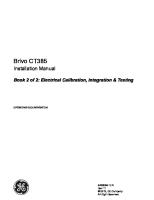
1.5 Layout of the transceiver The receiver unit, RA-7203 operates as an independent receiver. The transmitter unit TA-7650 operates as an independent transmitter, but requires a power supply unit; PSU-7006 or PSU-7007 for operation using AC power. The receiver and transmitter units may be placed in entirely different geographical locations or together in a single enclosure, it may also be configured as a transceiver with local operation from the front panel.
Figure 1.1, Complete Transceiver, RA-7203, TA-7650 and PSU-7006
1.6 Applications The transmitter TA-7650 and the receiver RA-7203 can be used either as a standalone transmitter / receiver for ground to air voice or data communication, or combined as a transceiver with RX muting and common audio control via the interface of the Transmitter unit. The following operating scenarios are available: • • • • • •
•
Locally as a Transceiver, with microphone and headphone connected directly to the front panel connector. As a Transceiver, connected to a VCS (Voice Control System) using 600-ohm analogue lines for audio, together with keying in form of in-band tones, external voltages, ground or phantom keying (E&M signalling). As a Transceiver, connected to a VCS (Voice Control System) using Ethernet (LAN/WAN) for VoIP audio, keying and signalling. Connected to a VME (VHF ground station) system as a data modem, using TCP commands to control the radio as a physical VDL mode 2 transceiver. Connected to a VDL (VHF ground station) system using 600-ohm analogue lines for audio that contains the AM-MSK data from an external ACARS modem. In a combined system where the radio is connected to an IP based VCS, an analogue based VCS and a local system using microphone/headset. The radio can be set up to automatically select the audio from either of the systems based on the keying source. This flexibility makes the radio ideal to use in a transition phase between an analogue and an IP based VCS system. In addition the transmitter/receiver has a large range of options for remote control using Ethernet, serial lines or front panel controls.
Jotron AS| TR7750: Operators handbook ➔ Introduction P/N: 84496 (v.T)
Page 1-4
2 Technical SPECIFICATIONS 2.1 General specification, TR-7750 Applicable Standards AM, AM-MSK VDL mode 2 Voice over IP EMC Random Vibration Bump Free Fall
ICAO annex 10, ETSI EN 300676 ETSI EN-301841 - 1 EUROCAE ED-137 (B) part 1,4 and 5 ETSI EN-301489 part 1/22, FCC rule 15B and 87, IC RSS-141 ETSI EN 300019-2-2(V2.1.2) method: IEC 60068-2-64 ETSI EN 300019-2-2(V2.1.2), method: IEC 60068-2-29 ETSI EN 300019-2-2(V2.1.2), method: IEC 60068-2-32
General, all units
AM 25 kHz
Frequency range Frequency accuracy (stability)
117.975 to 137.000 MHz (to 144.000 or 156.000 are optional) < ±1.0 ppm@ -20°C to +55 °C, 70 dBc up to 95% < 2% @85% modulation 300-3400 Hz 300-2500 Hz 1200/2400 Hz