![PC200-10M0CE Machine System [PDF]](https://pdfs.asia/img/200x200/pc200-10m0ce-machine-system.jpg)
8 0 6 MB
KLTD TTC Ref. No.: NG20-17-00
Machine Systems PC200-10M0(CE)
Komatsu Ltd.. Techno Training Center Komatsu City JAPAN
Manual Usage
● These course or course materials are not intended to replace the operator or shop manuals. It is the operator’s and technician’s responsibility to read and comprehend the operator and shop manuals and use them as sources of technical and operational information. Please review the Safety Material attached to this lesson. 2
Objective
Objectives
The improvements of PC200-10M0(CE) will be explained in comparison with the current model PC200-8M0. The explanation items are as follows. A: Design B: Fuel Saving C: Durability Improvement D: Serviceability Improvement E: Condition Monitoring Improvement F: ICT Tool Improvement G: Expandability Points H: Interchangeability
3
Table of Contents
A: Design B: Fuel Saving C: Durability Improvement D: Serviceability Improvement E: Condition Monitoring Improvement F: ICT Tool Improvement G: Expandability Points H: Interchangeability
4
5 6 - 12 13 - 16 17 - 30 31 - 35 36 - 43 44 - 46 47 - 50
A: Design PC200-10M0(CE)
PC200-8M0
5
B: Fuel Saving Technologies
Table of Contents B: Fuel Saving Technologies 1. Engine 2. Swing Controls (1). 2-stage Swing Relief Valve
6
7-8 9 - 12
B: Fuel Saving Technologies 1. Engine The engine is equipped with SAA4D107E-1, Tier 3 emission regulation compliant engine.
7
Item
Unit
PC200-10M0(CE)
PC200-8M0
Model
ー
KOMATSU SAA4D107E-1 (Tier3)
KOMATSU SAA6D107E-1 (Tier3)
Rated power(NET)
kW(PS)
103(140)
103(140)
Rated speed
rpm
2,000
2,000
Cyl. – Bore x Stroke
mm
4-107x124
6-107x124
Capacity
cc
4,460
6,690
B: Fuel Saving Technologies 1. Engine Regarding PC200-10M0(CE)'s 4cylinder engine, blue color area (shows low fuel) is wider than PC200-8M0. In addition, PC200-10M0(CE) engine curve is used to be on more fuel-efficient area (blue color area). As the sacrifice of that, engine speed is decreased and pump flow is decreased, and then, productivity is also decreased.
Large fuel consumption
Low fuel consumption
(1). 4-cylinder Improved fuel efficiency in the main operating range and idle range by using four cylinders2.
8
(2). Torque curve change Implementation of output restrictions similar to the current Indonesian specifications
B: Fuel Saving Technologies 2. Swing Controls (1). 2-Stage Swing Relief Valve >This valve has 2 selectable setting for a set pressure. >The set pressure of this valve is determined by the load at installed length of spring (4). >During swing operation, the valve receives Pilot Pressure (PI) from the 2-stage swing relief solenoid valve and reduces the relief (drain) quantity. >According to Formula: (wasted) Energy = Pressure X Flow From 2-Stage Swing Relief Solenoid Valve (7)
Swing Machinery
>Fuel Consumption is greatly improved. 9
1. 2. 3. 4. 5. 6.
Valve seat Valve Poppet Spring Spring Piston
2-Stage Swing Relief Valve
B: Fuel Saving Technologies 2. Swing Controls (1). 2-Stage Swing Relief Valve From Energy = Pressure X Flow A) When Pilot Pressure is “Shut-Off” (Low Pressure Setting) B) When Pilot Pressure is “Activated” (High Pressure Setting) P: 28.4 MPa (constant) Q1: 180L/Min Q2: 70L/Min A) Set Pressure is the load at Installed Length of Spring (4) Increase the PC-EPC current to decrease the pump discharge rate .
Relief
B) Swing Acceleration is done and (PI) is supplied @ d2-d1 (green). Spring is compressed and load is increased. Passage of Valve 2 and 1 is narrowed while pump supply and Relief Oil flow are decreased. 10
B: Fuel Saving Technologies 2. Swing Controls (1). 2-Stage Swing Relief Valve During Swing Acceleration, the set pressure of the 2-Stage Swing Relief Valve is changed to decrease the flow rate to hydraulic relief and improve the fuel consumption ratio.
When starting swing
1. 2. 3. 4. 5. 6.
Relief Valve Check Valve Check Valve Shuttle Valve Shuttle Valve Control Valve
Tip: If the pilot pressure is not supplied due to a solenoid disconnection, a poppet stuck or damage and etc, the two-stage setting is disabled, and the drain amount does not decrease. Symptoms: Consumption of fuel will increase like (PC200-8)
11
When stopping swing
B: Fuel Saving Technologies 2. Swing Controls (1). 2-Stage Swing Relief Valve
A: Flow rate at low pressure setting B: Flow rate at high pressure setting C: Flow rate needed for Swinging
Z: Loss Reduction (improved fuel efficiency) in relief operations TARGET: Make the flow rate as close as possible to the flow rate ONLY needed for Swinging
Target: Drain / Relief Discharge Rate (Q) Reduced Condition: Relief Pressure Constant Action: Additional pilot pressure increases the installed load and 12 increases the relief pressure setting – reduces fuel consumption
C: Durability Improvement
Table of Contents C: Durability Improvement 1. Fuel System 2. PPC Hose - Face Seal 3. Removal of Greasing Tube at the Swing Circle
13
14 15 16
C: Durability Improvement 1. Fuel System Improvement ✔Improvement of fuel filtration Fuel filtration was changed according to region (1)Strategic Area
*Not Replaceable during maintenance, only at OV. Filter element has no Part Number only assembly number as one with the Engine. Mesh Size same with Main Filter. Will issue PSN this November 2018. Effective for customers who refill bad fuel at clean side during filter exchange.
Water separator
CAP with vent
Water separator
STD Pre-filter
Fuel filter
Feed pump Fuel prefilter
Main filter Engine oil filter
(2)Strategic Special Area (Indonesia)
No vent CAP + Additional Breather
Additional Water STD Pre-filter Pre-filter separator (for dust)
Feed pump
Main filter
14
Dust protector*
C: Durability Improvement 2. PPC Hose - Face Seal Connector
✔ISO Control 15
(Most Common)
✔SAE Control
(Common in U.S.)
C: Durability Improvement 3. Removal of Greasing Tube at the Swing Circle ✔Abolished the remote greasing tube at swing circle to prevent breakage of remote greasing tube PC200-10M0(CE)
PC200-8M0
Embedded Grease Nipple
16
Removed this remote lubrication tube
D: Serviceability Improvement
Table of Contents D: Serviceability Improvement 1. Single Oil Cooler 2. Easy Removal of Dust-Proof Net 3. Dust-Proof Net Mounting 4. Remote and Direct Drain for Fuel 5. Hand Priming Pump Change 6. PTO Oiling Method 7. Drain Port to Suction Pipe 8. Engine Hood Mechanical Lock Bar 9. Integration of Oil Level and Lubrication Pipes at Swing Machinery 10. Service Pressure Sensor 11. Battery Disconnect Switch and System Operation Lamp (Opt.)
17
18 19 20 21 22 23 24 25 26 27 - 29 30
D: Serviceability Improvement 1. Single Oil Cooler Core
Single Oil Cooler Core The oil cooler core is changed from 2 sheets to 1 sheet to improve the cleaning performance. In addition, by adopting a new type of core, cooling efficiency is improved. 18
D: Serviceability Improvement 2. Easy Removal of Dust-Proof Net Dust-proof net removability is improved by changing piping route and putting a back-up plate in the net overlapping part. Changing piping route
A
A
Place the backup plate in the net overlapping part to fill the crevice of the net.
A-A
19
PC200-10M0(CE)
PC200-8M0
D: Serviceability Improvement 3. Dust-Proof Net Mounting Dust-proof net on the cooling assembly. is remotely attached through clamps positioned at the top and its detachability is improved with 3 Wing Nuts which are supported by Brace at the bottom.
20
D: Serviceability Improvement 4. Remote and Direct Drain for Fuel Change of the drain structure of the fuel tank PC200-10M0(CE)
PC200-8M0
Fuel Remote Drain + Direct Drain for Cleaning
Remote Drain System
Applied to other regions like in China
*If remote drain piping will be clogged, it can not be cleaned.
Operate drain cock at pump room
Provides port for direct draining of deposits on the bottom of the tank aside from the remote drain circuit. Cleaning is still possible even if 1 drain system is clogged. 21
D: Serviceability Improvement 5. Hand Priming Pump Change Hand priming pump handle shape improvement.
Convex Shape Priming Handle >Less stress to the hand 22
Concave Shape Priming Handle >More stress to the hand
D: Serviceability Improvement 6. Damper case Oiling Method Change of Damper case Oiling Method PC200-10M0(CE)
PC200-8M0
Breather/Oiling Port
Oil Level Port
Breather/Oiling port 23
Oiling Port is closed with Red Plug for good visibility
D: Serviceability Improvement 7. Drain Port to Suction Pipe Addition of drain port to suction piping. PC200-10M0(CE)
PC200-8M0
No Drain Port
Suction Drain Port
24
The remaining hydraulic oil that settled in the suction piping can be drained.
Hydraulic Fluid Temperature Sensor Port
D: Serviceability Improvement 8. Engine Hood Mechanical Lock Bar Addition of Hood Mechanical Lock Bar/Stopper. PC200-10M0(CE)
Effective for preventing accidents during maintenance. 25
PC200-8M0
No Hood Mechanical Lock Bar/Stopper
D: Serviceability Improvement 9. Integration of Oil Level and Lubrication Pipes at Swing Machinery Integration of oil level pipe and lubrication pipe in swing machinery PC200-10M0(CE)
26
PC200-8M0
D: Serviceability Improvement 10. Service Pressure Sensor Addition of Service Pressure Measurement on the Monitor Panel (Service Pressure Sensor) Pump Room has 1 open connector to connect the Service Pressure Sensor: AMP3 Pin Connector
Inside the right-side Pump Room Cover
Plug
Wiring Harness and Connector No. P49 is found beside the inner RHS Frame of the Pump Room Example: R-pump, LS Pressure Measurement
27
By Utilizing this Port, Pump Pressure and LS Working Pressure can be determined using a Service Pressure Measuring Jig.
Service Pressure Sensor (50 MPa) is connected to the Rear Pump LS 27Pressure Detection Port
D: Serviceability Improvement 10. Service Pressure Sensor 50 MPa-Service Pressure Sensor
50 MPa-Service Pressure Sensor is enough to measure even low pressures during measurement. 28
D: Serviceability Improvement 10. Service Pressure Sensor Monitoring of Service Pressure Rear Pump Pressure (readily available) and the LS (Rear Pump) Pressure (by service pressure sensor) can be displayed both on the monitor panel.
Procedures for Monitoring:
(after the Service Pressure Jig has been connected and set-up on the rear pump LS pressure port)
Go to PUMP Menu and search for Search as well the Rear Pump Service Pressure Sensor Item (01141) Pressure Item (01101) or input both Number Codes directly
Long Press Check Icon Button (F6) and start monitoring.
Procedures for Set-Up 1 . Set the items to be measured and perform servicing. Select the Correct Pressure Sensor (50 or 5 MPa).
2. Install a nipple on the pressure detection port; connect the sensor. 3. Connect the harness to the CN-P49 (Service Pressure Connector).
29
4. Enter service mode in monitor panel and select Monitoring.
D: Serviceability Improvement 11. Battery Disconnect Switch and System Operation Lamp (Opt.) System Operation Lamp indicates that power is supplied to the installed controller. >GREEN Light: when controller is powered ON and normally turns OFF when starter switch is OFF. >NO LIGHT: After 1-5 seconds of starter switch at OFF Position. >Data communication occurs in controller when this light is tuned ON. Turn OFF battery disconnect switch ONLY when there is no light, some Data might be lost.
30
E: Condition Monitoring Improvement
Table of Contents E: Condition Monitoring Improvement 1. Blowby Pressure Sensor 2. Hydraulic Return Oil Filter Clogging Sensor 3. Breaker Filter Clogging Switch
31
32 - 33 34 35
E: Condition Monitoring Improvement 1. Blowby Pressure Sensor Failure prevention of engine by monitoring blowby gas pressure.
Blow-by gas pressure sensor
Note: If disconnected or damaged, Error Code:DHE5MA and Action Code:L0a is generated (Error Info sent to KOMTRAX but no Buzzer Sound)
32
E: Condition Monitoring Improvement 1. Blowby Pressure Sensor Monitoring Blowby pressure sensor with / without setting screen option: >Service Menu-Default-Option-With/Without Blowby Pressure >Choose WITH (if equipped)
Blowby Pressure Measurement Method
Display the following monitoring screen from the service menu and execute: >Swing Lock: ON, ARM DIG Relief + 1 Touch Power and Monitor Value. >The failure judgment reference value is 1.96 kPa and it is the same with the current one (PC200-8M0). 33
E: Condition Monitoring Improvement 2. Hydraulic Return Oil Filter Clogging Sensor Addition of Clogging Detection Function by using Stroke Sensor to Hydraulic Oil Return Filter. >Hydraulic equipment protection by installing hydraulic oil filter clogging detection sensor >Clogging Sensor opens a bypass when the filter is clogged. This opening is monitored by a stroke sensor. Once the gap is reached, error code: DKR2NX appears, caution lamp lights up in yellow and L01 action code is displayed.
Clogging Sensor Stroke Mechanism
> If sensor is disconnected or damaged, error code: DKR2MA appears. (Action code is not displayed.) >No Calibration is required if replacement is done. >Bypass Valve Set Pressure: 250 +- 50 KPa (Same with PC210-10M0)
34
Note: The exchange of filter is based on conventional time interval. However, when filter clogging is detected, replacement is needed to prevent contaminated oil to flow downstream in order to prevent failure.
E: Condition Monitoring Improvement 3. Breaker Filter Clogging Switch Addition of Clogging Switch to the Breaker Filter (Optional) >Improvement of hydraulic oil filtration when using the Breaker attachment. Equipped with a clogging switch for ATT return filter.
Pressure loss (kPa)
ATT return filter characteristics
Clogging switch equipped to the ATT return filter
Clogging rate (%)
>As the Clogging Rate of the filter increases, pressure loss with increased filter efficiency also rises sharply. This rising degree is detected by the Clogging Sensor Switch, and it informs clogging. >If clogging occurs, buzzer sounds with L01 action code. Machine output restriction is not applied.
35
Note: The exchange of filter is based on conventional time interval. However, when filter clogging is detected, replacement is needed to prevent contaminated oil to flow downstream in order to prevent failure.
F: ICT Tool Improvement
Table of Contents F: ICT Tool Improvement 1. Maintenance Screen Items 2. Maintenance Screen Actual Monitor 3. Language Selection Improvement 4. E-Mode Adjustment Function 5. Remaining Hours of Breaker Filter 6. Blowby Pressure Measurement Monitoring 7. Monitoring Item List
36
37 38 39 40 41 42 43
F: ICT Tool Improvement 1. Maintenance Screen Items
Double the Time for Replacement: 500 H → 1000 H PC200-10M0(CE)
Maintenance item
PC200-8M0
Default maintenance time setting (h)
Time remaining until maintenance
Default maintenance time setting (h)
Time remaining until maintenance
Air cleaner check and cleaning
ー
ー
ー
ー
Additional hyd. oil filter change
250 (*1)
250 (*1)
Fuel prefilter change
500
500
500
500
Engine oil change
500
500
500 (*1)
500 (*1)
Engine oil filter change
500
500
500 (*1)
500 (*1)
Additional fuel filter change
500 (*1)
500 (*1)
Fuel tank breather change
500 (*1)
500 (*1)
Hyd. oil tank breather change
1000
1000
500
500
Fuel main filter change
1000
1000
1000
1000
Damper case oil check / refilling
1000
1000
1000
1000
Swing machinery case oil change
1000
1000
1000
1000
Hyd. oil pilot filter change
1000 (*1)
1000 (*1)
Final drive case oil change
2000
2000
2000
2000
2500(*2)
2500(*2)
1000
1000
Coolant change
4000
4000
Coolant filter change
4000
4000
Radiator cap change
4000
4000
Hyd. oil change
5000
5000
5000
5000
Hyd. oil filter change
*1: The interval is set for only that specification machine. *2:The replacement interval may become shortened depending on dust situation of application.
EVERY 4000 HOURS MAINTENANCE METHOD FOR REPLACING RADIATOR CAP ................................................ 4-89 METHOD FOR REPLACING COOLANT FILTER CARTRIDGE............................ 4-90 METHOD FOR CHANGING COOLANT.......................................................... 4-90
37
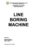
New/Updated Maintenance Items are in Red Colors
F: ICT Tool Improvement 2. Maintenance Screen Actual Monitor
38
2500
2498
2500
2498
F: ICT Tool Improvement 3. Language Selection Improvement Select language switch button and scroll to the highest order for options to switch language easily.
A Blinking
A Check display if selected language was applied
39
Dual language menu display
F: ICT Tool Improvement 4. E-Mode Adjustment Function
Main Monitor Panel Screen Press F6.
Select E-Mode Type : E0 to E3
40
Select Machine Setting and Press F6 to choose for Different Working Mode
Select E-Mode Type : E0 to E3
F: ICT Tool Improvement 5. Remaining Hours of Breaker Filter Display of Remaining Hours of Breaker Filter
41
F: ICT Tool Improvement 6. Blowby Pressure Measurement Monitoring
Hold Button 4+1,2,3 > Service Menu
Select 42803 Item (Blowby Pressure)
42
Select Self-Define Monitoring
Select PUMP Tab
F: ICT Tool Improvement 7. Monitoring Item List
43
PC200-10M0 Monitoring item Code No. (Displayed in screen) 01002 Engine speed 01100 F pump pressure 01101 R pump pressure 01141 Service pressure sensor 01300 PC-EPC sol current (F) 01302 PC-EPC sol current (R) 01500 LS-EPC sol current 03203 Battery power supply 04107 Coolant temperature 04401 Hydr. oil temperature 04501 Engine oil level 07102 Travel Fwd LH PPC pressure 07103 Travel Fwd RH PPC pressure 07104 Travel Rev LH PPC pressure 07105 Travel Rev RH PPC pressure 07200 Arm In PPC pressure 07300 Bucket Curl PPC pressure 07301 Bucket Dump PPC pressure 07400 Boom Raise PPC pressure 07500 Boom Lower PPC pressure 07600 Arm Out PPC pressure 09001 Swing Left PPC pressure 09002 Swing Right PPC pressure 18500 Boost temperature 36200 Rail pressure command 36400 Rail pressure 36500 Charge pressure 37212 Engine oil pressure switch 37400 Ambient pressure 42803 Blowby pressure
Unit(SI) Applicable r/min Mpa Mpa Mpa mA mA mA V ℃ ℃ ー Mpa Mpa Mpa Mpa Mpa Mpa Mpa Mpa Mpa Mpa Mpa Mpa ℃ Mpa Mpa Mpa ー kPa Mpa
ENG PUMP PUMP PUMP PUMP PUMP PUMP ENG ENG PUMP MON PUMP PUMP PUMP PUMP PUMP PUMP PUMP PUMP PUMP PUMP PUMP PUMP ENG ENG ENG ENG ENG ENG PUMP
PC200-8M0 Monitoring item Code No. (Displayed in screen) 01002 Engine speed 01100 F pump pressure 01101 R pump pressure
Unit(SI) Applicable r/min Mpa Mpa
ENG PUMP PUMP
01300 01302 01500 03203 04107 04401 04501 07102 07103 07104 07105 07200 07300 07301 07400 07500 07600 09001 09002 18500 36200 36400
PC-EPC sol current (F) PC-EPC sol current (R) LS-EPC sol current Battery power supply Coolant temperature Hydr. oil temperature Engine oil level Travel Fwd LH PPC pressure Travel Fwd RH PPC pressure Travel Rev LH PPC pressure Travel Rev RH PPC pressure Arm In PPC pressure Bucket Curl PPC pressure Bucket Dump PPC pressure Boom Raise PPC pressure Boom Lower PPC pressure Arm Out PPC pressure Swing Left PPC pressure Swing Right PPC pressure Boost temperature Rail pressure command Rail pressure
mA mA mA V ℃ ℃ ー Mpa Mpa Mpa Mpa Mpa Mpa Mpa Mpa Mpa Mpa Mpa Mpa ℃ Mpa Mpa
PUMP PUMP PUMP ENG ENG PUMP MON PUMP PUMP PUMP PUMP PUMP PUMP PUMP PUMP PUMP PUMP PUMP PUMP ENG ENG ENG
37400
Ambient pressure
kPa
ENG
G: Expandability Points
Table of Contents G: Expandability Points 1. Breaker Operation and Maintenance 2. Breaker Operation and Maintenance from OMM
44
45 46
G: Expandability Points 1. Breaker Operation and Maintenance
When a hydraulic breaker is used, B mode should be selected, otherwise dirty oil goes to control valve that may cause premature wear in the slipper seals of pressure compensation valves. When B mode is selected, the pilot pressure pushes switch valve to change oil flow through the additional return filter that goes back to tank through the main return filter. B mode sets two accumulators to be operated to absorb pulsated oil flow to extend hydraulic components life including the hydraulic breaker.
45
G: Expandability Points 2. Breaker Operation and Maintenance from OMM Operation & Maintenance Manual
Notice If breaker operations are performed in a mode other than the breaker mode, there is danger of breakage of the hydraulic equipment. Do not perform breaker operations in any mode except the breaker mode. Maintenance interval for hydraulic breaker For machine equipped with a hydraulic breaker, the hydraulic oil deteriorates faster than the one for normal bucket digging operations, so set the maintenance interval as follows. ・Replace hydraulic filter element On a new machine, replace the element after the first 100 to 150 hours, then carry out further replacement of the element according to the table on the right. ・Change oil in hydraulic tank Change the oil according to the table on the right. ・Replacing additional filter element for breaker ( if equipped) Replacing additional pilot filter element for breaker (if equipped) Use a guideline of 250 hours for use of the breaker (operating ratio for the breaker: 50% or more) and replace the element according to the table at the right.
46
H: Interchangeability
47
H: Interchangeability Device Cooling assembly Operator's cab
Operator's seat
Hydraulic tank assembly Fuel tank assembly Boom assembly Unit
Arm assembly Bucket assembly Revolving frame Track frame Final drive assembly Sprocket Machine cab Controller
48
Interchangeability to PC200-8M0 New Old × M/C -8M0 × New Old × M/C -8M0 × New Old ○ M/C -8M0 ○ New Old × M/C -8M0 × New Old × M/C -8M0 × New Old × M/C -8M0 × New Old × M/C -8M0 × New Old ○ M/C -8M0 ○ New Old ○ M/C -8M0 ○ New Old × M/C -8M0 × New Old × M/C -8M0 × New Old ○ M/C -8M0 ○ New Old ○ M/C -8M0 ○ New Old × M/C -8M0 × New Old × M/C -8M0 ×
Reason for no interchangeability Change core size
Any advice to use noninterchangeable device
Change install parts In case of floor mount for console In case of ope seat mount for console Change welding seats etc. Change flange for stroke sensor Change welding seats etc. Delete mirror mount portion Change piping layout
Same as PC210-10M0 Same as PC210-10M0
Change structure (VE) Change shape Change length Change structure (VE) Same as PC210-10M0 Change mount portion for idler cushion
Change structure Control logic change Change internal IC
Remarks
H: Interchangeability Device Monitor Engine controller Work equipment ppc valve Travel ppc valve Unit Damper Solenoid valve Air conditioner Counter weight
49
Interchangeability to Reason for PC200-8M0 no interchangeability New Old Control logic change × M/C -8M0 × New Old Control logic change × M/C New M/C New M/C New M/C New M/C New M/C New M/C
× ○ ○ ○ ○ ○ ○ × × × × × ×
-8M0 Old -8M0 Old -8M0 Old -8M0 Old Change no of solenoid -8M0 Old Change piping hose -8M0 Old Change weight, size and mount bolt -8M0 position
Any advice to use noninterchangeable device
Remarks
H: Interchangeability Device Engine oil filter Fuel filter Fuel pre-filter Hydraulic oil filter ATT return filter Consum ATT accumulator ption ATT pilot filter Air cleaner element Fan belt Belt for compressor for air conditioner Hydraulic hose
50
Interchangeability to PC200-8M0 New Old × M/C -8M0 × New Old ○ M/C -8M0 ○ New Old ○ M/C -8M0 ○ New Old ○ M/C -8M0 ○ New Old × M/C -8M0 × New Old × M/C -8M0 × New Old ○ M/C -8M0 ○ New Old ○ M/C -8M0 ○ New Old × M/C -8M0 × New Old × M/C -8M0 × New Old × M/C -8M0 ×
Reason for no interchangeability Change capacity and performance improvement
Any advice to use non-interchangeable
Change filter
Change accumulator (change maker)
Remarks
Installed at only ATT spec. Installed at only ATT spec. Installed at only ATT spec.
Change belt length Change belt length Change length and diameter
KLTD TTC Ref. No.: NG20-17-00
Machine Systems PC200-10M0(CE)
Komatsu Ltd.. Techno Training Center Komatsu City JAPAN