![PDC On Rotating [PDF]](https://pdfs.asia/img/200x200/pdc-on-rotating.jpg)
14 0 623 KB
NEW TOOLS FOR DIAGNOSTIC MEASUREMENTS ON ELECTRICAL ROTATING MACHINES
Michael Krüger, Giorgio Galimberti, OMICRON Austria Avi Baram, Manbar Tech, Tel Aviv, Israel [email protected]
Rotating machines are important and expensive assets in electric power systems. Recurring diagnostic measurements on the electrical insulation of stator and rotor are important to ensure the safe operation and prevent unexpected outages and serious failures. Common practise for the insulation diagnosis is the measurement of the Polarisation Index (PI), the measurement of the capacitances and dielectric losses and the measurement of partial discharges (PD). Innovative tools like the dielectric response analysis or the partial discharge measurement with synchronous multichannel systems enable a more detailed analysis of the insulation quality and the location of faults. The dielectric response analysis of the insulation with Polarisation / Depolarisation Current (PDC) and Frequency Response Spectroscopy (FDS) can detect moisture and ageing problems much better than measuring the PI only. With PD systems which can measure simultaneously at different points, different PD sources can be separated from each other and from interference. Additionally multi-frequency PD measurement systems allow for pulse shape analysis. This way PD faults can be seen and also located much easier. Such PD systems can also be used in online monitoring systems with great advantages. In the paper the new methods of insulation testing and monitoring are described and the advantages of these tools are illustrated with practical case studies. .
KEYWORDS Dielectric polarization, dielectric losses, frequency domain analysis, rotating machine insulating testing, partial discharges
[email protected]
INTRODUCTION The technical diagnostic of electric machines is a necessary tool for the condition evaluation. Normally a condition based maintenance strategy is applied for power equipment with a high asset as generators represent. The aim of the technical diagnostics is to detect any anomalies of the electric insulation system. A common procedure for testing the electrical insulation system of generator stator windings is the measurement of the insulation resistance, the dielectric dissipation factor and the partial discharges. For these tests there were some routines and standard procedures and test equipment used. The insulation resistance is tested according to the IEEE 43 [1] at DC, the dielectric dissipation factor normally is tested at AC according IEEE 286 [2] and the partial discharges according IEEE 1434 [3] respectively IEC 60270 [4] and IEC 60034-27 [5]. In these standards were some specifications about the test procedure but no declaration of the test voltage.
form wound coils and 5M for random wound coils after 1 minute is recommended in this standard [1], [8]. Additional to above results, the dryness of winding insulation can be evaluated according to [6]. The time constant of the insulation system can be calculated by the product of the insulation resistance after 10 minutes and the capacitance of the winding according to formula (1): 10 = R10 x C0,2 [s] 10 R10 C0,2
(1)
insulation time constant insulation resistance after 10 minutes capacitance at 20% of rated voltage
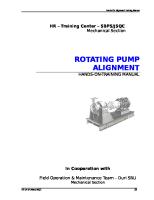
In dependence of the measuring temperature the limit for the dryness decreases linear in a single log scale, corresponding to Figure 1. The limit of dry/wet windings was found empirical by generator onsite measurements [6].
DIELECTRIC RESPONSE INSULATION RESISTANCE MEASUREMENT The procedure for measure the insulation resistance can be found in [1]. A DC test voltage has to be applied as step function on the totally depolarized winding for the duration of 10 minutes. Due to different polarization processes the resulting current decreases in dependence of the condition of the insulation system faster or slower. The components of the total current were the sum of absorption, conduction, leakage and capacitance of the winding. The capacitive part normally can be neglected. The leakage portion represents the surface condition and humidity of the end windings. The conduction is dependent on the volume resistance and therefore the temperature is a big influence factor. And at least the absorption represents the polarization mechanism in the solid insulation system. Which information for the condition can we extract form the results of insulation resistance measurements? At first the polarization index (PI) is one factor. According to the standard the ratio between the resistance at end (10min) and beginning (1min) of the measurement should be greater than 2.0 according to [1]. The reason can be found in the dominant leakage current and/or low volume resistance for humid or contaminated windings. Dry and clean insulation systems have an essential higher PI than 2.0. At second the value of the insulation resistance is an absolute criterion for the quality and the global condition. A minimum of 100M for
Fig. 1 Insulation time constant of stator windings with definition of dry and humid insulation
To verify the dryness of the winding system a dielectric response measurement can be applied. Normally this measuring technology is used to determine the water content of paper oil insulation systems used in transformers. Two methods are commonly used: the polarisation / depolarisation
1
CAPACITANCE AND THE DIELECTRIC DISSIPATION (POWER) FACTOR The dielectric losses are defined as dielectric dissipation factor (DF = tangent delta) in the IEC standards or as power factor (PF = cosine phi) in the IEEE standards. The dielectric losses versus voltage characteristics of coil insulation are the result of several phenomena occurring in the insulation structure. Ionisation of gaseous inclusions (voids) in the insulation structure causes an increase in dissipation factor with voltage increase as the critical voltage gradient is exceeded. Void ionisation is a form of partial discharge. Fig. 2 FDS in the frequency domain
current (PDC) in the time domain and the frequency domain spectroscopy (FDS) in the frequency domain. Both methods deliver results which are comparable. The advantages and disadvantages of these methods were discussed in [7]. An innovative
The PF tip-up according to IEEE 286-2000 [2] is defined as the difference in the power factor measured at two voltages (figure 5). When testing an individual coil or bar, this change in power factor with the test voltage may be caused by either a variation in the power factor values associated with the dielectric or partial discharges losses, or both with voltage. The power factor component arising from the dielectric losses generally changes very little with voltage; however, with some defects in the solid insulation, such as uncured resin sections or contamination due to ionic impurities, significant space charge losses may arise leading to an increasing or decreasing tan δ value with voltage. The delta tan-δ test according to IEC 60894 [9] is shown in figure 6. Here the difference between each two results at 0,2; 0,4; 0,6; 0,8 and 1,0 times the test voltage is recorded.
Fig. 3 PDC in the time domain
algorithm joins the advantages of both measuring principles and applies the FDS method for high frequencies and PDC method for low frequencies within a much shorter measuring time compared to the other methods. The result can be shown in the frequency or time domain (figures 2 and 3) [8]. The test setup is shown in figure 4.
Fig. 5 Power factor tip-up test (IEEE 286-2000)
In many cases the dielectric response delivers much more information about the condition of the insulation as the insulation resistance and the PI only. The PI can be calculated from the polarisation currents for 60s and 600s.
Fig. 6 Delta tan-δ test (IEC 60894)
2
Fig. 4 FDS / PDC measurement
PARTIAL DISCHARGE MEASUREMENT The DF/PF measurement is an integral measurement of the whole winding insulation. With the partial discharge (PD) measurement also single faults in the insulation can be found. PD multi-channel systems with synchronous measurements enable for the separation of the single PD sources by Three-PhaseAmplitude-Relation-Diagram (3PARD) filtering. The responses of the three channels at the three phases are added like phasors in the 3PARD diagram (figure 7). With off-line one phase tests instead of three phases, three channels at different locations are used: Ch1=U1, Ch2=U2 and Ch3=V (figure 8).
Simultaneous measurement of the capacitance, the dielectric dissipation factor and partial discharges Figure 9 shows the test arrangement for simultaneous measurements of capacitance, dielectric dissipation factor and of partial discharges of the phase U at the high voltage side U1 (MPD600/1), the star point U2 (MPD600/2) and the head windings U1-V1 (MPD600/3) and U1-W1 (MPD600/4).
C-tanδ
Fig. 7 3-Phase-Amplitude-Relation-Diagram(3PARD)
Fig. 9 Simultaneous measurement of capacitance, tan-δ and partial discharges
CASE STUDY OF DIAGNOSTIC MEASUREMENTS ON A HYDRO POWER GENERATOR Diagnosis measurements were done on a hydro power generator with a rated voltage of 6400V. First a PDC/FDS measurement was carried through. The results are shown in figures 10 and 11.
Fig. 8 PD separation by 3PARD filtering
3
During the injection of the current an infrared camera was used to check the temperature distribution of the winding. Some areas showed higher temperatures than the average. A winding resistance measurement was made (figures 13 and 14). It showed that the resistance in phase W was increased by more than 20%. It was detected that some of the soldered coil connections were broken. There were resoldered properly.
Fig. 10 FDS measurement
Fig. 13 Winding resistance measurement
0.05Ω 0.04Ω Fig. 11 Polarisation current measurement
0.03Ω The phase R (=U) showed a totally different behaviour compared to the phases S (=V) and T (=W). The 50Hz dissipation factor of phase R was 3.8% compared to 1.8% of phases S and T. The dissipation factor at 10mHz was 300% in phase R, compared to 5% in phases S and T. The polarisation current (at 600s) in phase R was 1000 times higher than the currents in S and T. Out of this reason it was decided not to make any high voltage test on this generator but to dry it first by loading the three winding with 250A DC.
U V
0.02Ω
W
0.01Ω 0.0Ω Fig. 14 Winding resistance results
Fig. 15 Broken soldered connections Fig. 12 Infrared temperature measurement
4
After drying the FDS / PDC measurements were repeated, Figures 16 and 17 show the results.
It can be seen in figure 16 that the 50Hz dissipation factor is the same before and after drying, whereas the losses at 10mHz are reduced from 300% to 50%. But the losses are still high in comparison to the phases S and T. The insulation current at 600s is 10 times lower than before drying. The stator windings were cleaned but the losses were still high. It was decided to apply high AC voltage to the winding rising in 10% steps with accompanying PD measurements (figure 18).
Fig. 16 FDS before and after drying
Fig. 19 PD at 2.5kV on U and X
At a test voltage of only 2.5kV high partial discharges of 103nC at the star point and cross coupled PD’s with 18nC on the HV side were detected (figure 19). The origin of the strong partial discharges could be located with an ultrasonic receiver (figure 20). Fig. 17 PDC before and after drying
Fig. 20 PD location with an ultrasonic receiver
Fig. 18 PD testing
The conductor from the winding to the star point terminals was not properly insulated from the iron support beam (figure 21). But also this result had nothing to do with the high losses in phase R. Now the winding of phase R was tested with the rated phase to phase voltage of 6400V in steps of 10%. At 6400V a breakdown occurred after 10s (figure 21). The faulty coil could be found by detecting the fault current with a clamp-on ammeter (figure 22).
5
Fig. 21 PD source at the conductor to the star point
Fig. 22 Location of the faulty coil
Fig. 21 Breakdown of phase R at 6400V
For repairing the bad coil was cut off and the open winding ends were connected to each other. Table 1 shows all results of dielectric response measurements:
Phase R before drying and repair after drying before repair after repair
I DC at 600s 5.8uA 513nA 2.8nA
Figure 23 shows the comparison of the PDC results, figure 24 of the FDS before drying, after drying and after repair. The repaired generator passed all tests successfully.
PI 1.4 1.4 5.6
TanDelta 50Hz 3.9% 3.8% 1.9%
TanDelta 10mHz 300.0% 50.0% 4.5%
Table 1 Dielectric response measurement on phase U
Fig. 23 Polarisation current before and after repair
Fig. 24 FDS before and after repair
6
REFERENCES [1] IEEE Std 43-2000: “IEEE Recommended Practice for Testing Insulation Resistance of Rotating Machinery”, IEEE standard [2] IEEE Std 286-2000: “IEEE Recommended Practice for Measurement of Power Factor Tip-Up of Electric Machinery Stator Coil Insulation”, IEEE standard [3] IEEE Std 1434-2000: “IEEE Trial-Use Guide to the Measurement of Partial Discharges in Rotating Machinery”, IEEE standard [4] IEC 60270-2000: “High-voltage test techniques Partial discharge measurements”, IEC standard [5] IEC 60034-27: Rotating electrical machines – Part 27: “Off-line partial discharge measurements on the stator winding insulation of rotating electrical machines”, IEC standard
[6] „Empfehlungen für die Zustandserfassung der Aktivteile rotierender elektrischer Maschinen“, ÖVE, 2nd Edition, 1990 [7] M.Koch, S. Tenbolen, M. Krueger, A. Kraetge: “Improved Moisture Analysis of Power Transformers Using Dielectric Response Methods”, MatPost07 - 3rd European Conference on HV & MV Substation Equipment, Lyon [8] C. Summereder, M. Muhr, M. Krüger et. al.: “Unconventional Diagnostic Methods for Testing Generator Stator Windings”, Electrical Insulation, September / October 2009 ISSN 0883-7554 [9] IEC 60894: “Guide for a test procedure for the measurement of loss tangent of coils and bars for machine windings”, IEC standard, first edition 198703
7