![Raft Foundations [PDF]](https://pdfs.asia/img/200x200/raft-foundations.jpg)
20 0 3 MB
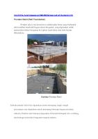
Raft foundations A raft foundation is a continuous slab of concrete usually covering an area equal to or greater than the base of the building or the structure to provide support for walls or lightly loaded columns and serve as a base for the ground floor. It spreads the load of the building over a larger area than other foundations, lowering the pressure on the ground. These are special cases of combined footings where all the columns of the building are having a common foundation. The word raft is used in the sense that the slab of concrete floats on the surface as a raft does on water. Raft foundations are used for lightly loaded structures on soils with poor bearing capacity and where variations in soil conditions necessitate a considerable spread of loads. Beam and raft and cellular raft foundations are used for more heavily loaded structures, where the beams or cells of a raft are used to provide wide spread of loads. This is an alternative if you can't use a traditional strip or trench fill foundations.
Applicability of Raft (Mat) Foundations Low bearing capacity soil, where ground
conditions are poor and strip or pad foundations would require significant excavation, for example on soft clay, alluvial deposits, compressible fill, and so on. Where spread footings cover about 70% of the structure High structure loads For structures like chimneys, silos, tanks, large machines Structures and equipment sensitive to differential settlement Watertight construction under basements below groundwater table Highly compressible soil and extends to a great depth When floor areas are small
and structural loadings are low, such as in one or two-storey domestic construction. It is employed for the construction of commercial buildings where the loads are commonly large. Mat foundations are popular in areas where basements are common. Where a basement is required. Where it may be impractical to create individual strip or pad foundations for a large number of individual loads. In very general terms, if strip or pad foundations would cover 50% or more of the floor area, then a raft may be more appropriate. When the columns and the Shear walls are placed so closely, where the individual footings overlap each other.
Construction of Mat or Raft Foundations Remove dirt and excavate soil to a uniform and flat level. The foundation bed is then compacted by ramming. Then, a waterproof plastic sheet is laid over the earth. After that, pour around 7cm layer of plain cement concrete to create a perfectly flat and level base for the foundation. Lay reinforcement on spacers over the foundation bed. Reinforcements are provided in both directions in the form of steel mesh. Two meshes are reinforced at the top and bottom of the foundation to balance upward and downward bending forces. After all the steel has been put in place, concrete is poured to the desired thickness, which is usually in the range of 200mm to 300mm thick for small buildings: this can be much thicker if heavy loads are to be carried. A minimum rebar cover of 50mm should be maintained.
Finally, a suitable curing regime should be used to make sure that concrete achieves the designated compression strength.
Basic framework of raft foundations -
Working Principle of Raft Foundations – It transmits the total load form the building to the entire ground floor area. The stress distribution mechanism of the raft foundations there is also very simple. When the total weight of the structure and self-weight of the mat calculate and divide by the total area of the foundation it is covering to calculate the stress on the soil. Since the raft ‘floats’ on the ground below, rather than being anchored in it, it is less prone to the effects of ground movement, due to settlements, for example. Forms of pressure in raft foundations The behavior of the raft foundation resembles the behaviour of a strip foundation grid. The stresses applied on the soil are larger in the columns area and smaller in the intermediate areas.
The presence of beams acting as stiffeners helps in a more even distribution of the soil pressures between the columns’ areas and the intermediate areas of the raft foundation.
Position of construction joint is to be provided in a raft foundation (if required)
Construction joint shall be provided preferably at a location where stress are zero Construction joint is provided at one-third or end of support. Also provide key and rebar to transfer shear stress if shear stress is not zero at point of construction joint. Provide construction joints as minimum as possible. Construction joint shall not be left on discretion of contractor. It must be approved by designer.
Types of Foundations Based on the method of their support, raft can be – Raft rests directly on the soil or beneath them but in some cases, they may be supported by piles
Type
Description
Raft supported on soil
It is essentially a continuous slab resting on the soil that extends over the entire footprint of the building, thereby supporting the building and transferring its weight directly to the ground below.
Graphics
Buoyancy raft
The buoyancy raft foundations are also known as compensated foundations or deep cellular rafts. Whatever be the name they are known for, they come under the category of floating foundations. These are known as fully compensated foundations as during their construction the soil underneath the foundation is removed, whose weight is equal to the weight of the whole superstructure. Hence the weight removed from the soil is compensated by the weight of the building. Those areas with soft soil, layer in a huge depth is observed, it is economical to go for floating foundation. No other foundation like pile foundation cannot be an efficient replacement for these. Occupants in low-altitude areas face the problem of high floods resulting in the collapse of houses. The construction of buoyant foundation would help in increasing the elevation of the house. This arrangement is a flexible method, as the building would remain on the ground under the normal conditions. When flood approaches, the building would rise to a necessary height.
Raft supported on piles
The addition of piles to a raft increases the
effective size of a foundation and can help resist horizontal loads which can improve the performance of the foundation in reducing the amount of settlement and differential settlement, as well as improving the ultimate load capacity. Piles under raft help in reducing settlement and provides resistance against buoyancy. Uses o Piled raft foundations are typically used for large structures o in situations where soil is not suitable to prevent excessive settlement. o They are an increasingly popular choice for high-rise buildings. o water table is close to the ground surface or when the minimization of settlement is extremely important for the serviceability of the superstructure. o structures that require a single foundation element, such as silos, tanks and chimneys. During the design process, the optimum number and position of piles, as well as their diameter, reinforcement and length, is
With beam
determined to ensure the stability of the structure while providing an economical solution, with the raft and piles acting together to ensure the required settlement is not exceeded. Typically, the piles provide most of the stiffness while the raft provides additional capacity at the ultimate loading. If there are one or more ineffective piles, the raft can allow some degree of load redistribution to other piles, reducing the influence of the pile’s weakness on the overall performance of the foundation. In an Unconnected Piled Raft Foundation (UCPRF), the piles are not directly connected to the raft, but are separated from it be a structural fill 'cushion' (such as a compacted a sand-gravel mixture or compacted soil) which redistributes load between the raft and piles. This can be a more efficient, and so economic solution. Whereas a standard raft foundation involves a concrete slab that sits on compressed ground, the slab in a piled raft sits instead on a number of much deeper pile foundations that are bored deep enough to reach a suitably stiff soil layer. These piles are long, thin footings made of reinforced concrete or steel, and they are spaced evenly across the site. The raft then ‘floats’ on top of these pilings.
edge Stiffened raft slabs consist of: o 100 mm thick concrete slab o edge beams o internal beams - (except Class A and Class S sites) o steel reinforcement o The concrete is poured in one operation. The stiffened raft configuration can be used on all classes of sites (except problem Class P).
Innovative piled raft foundation scheme used on building project in London The construction site of the 33-storey student accommodation building at Miles Street, London was too tight to fit a piling rig, thus the engineering team adopted an alternative piled raft foundation solution for the building's support. The Urbanest Student Accommodation building is being constructed with a slip formed core, on a small site, with a quite tight construction timeline. The challenges concerning its foundation had to do with the combination of a restricted 1000 m2 triangular site next to a Network Rail viaduct and several existing buildings (meaning sensitive settlement requirements), as well as a deadline to start work, meaning that a pile load test to reduce the design factor of safety was not possible. Without such a test, Balfour Beatty - contractor of the project - could only use piles of 1200mm diameter in order to achieve the loads. However, the necessary piling rig would have been too big for the site. In cooperation with geotechnical consultant CGL, structural engineer Walsh Associates proposed an innovative piled raft foundation as a solution to the problem. They designed a lean concrete frame to reduce the foundation loads, supporting it with a piled raft, using high and deep level ground support capacities to limit deflections. Along with the design of a slip formed core for the building, drainage was also placed on top to shorten the required design time, allowing the construction of the foundation before the drainage scheme was fixed, while water attenuation pipes were used instead of the typical attenuation tanks.
Based on the structural system adopted for the raft – Type
Description
Solid slab In solid raft foundations, there is only raft one unified foundation slab. foundations It is the simplest form of Raft foundation and its formwork assembling as well as its reinforcement is usually very easy. The flat slab raft is of uniform thickness under the whole of the building and reinforced to spread the loads from the walls uniformly over the under surface to the ground. This type of raft may be used under small buildings such as bungalows and two storey houses where the comparatively small loads on foundations can be spread safely and economically under the rafts. Sometimes referred to as a plain raft, and including; flat rafts, mats, wide toe rafts, slip plane rafts, blanket rafts, and so on.
Graphics
Flat Mat
Plate This type of mat is used when the columns and walls are uniformly spaced at small intervals and the subjected loads are relatively small. Raft of uniform depth is most popular due to its simplicity of design and construction. This type is most suitable where the column loads are moderate and the column spacing fairly small and uniform. Reinforcement is placed in both directions and more reinforcement is required at the column locations and load-bearing walls. Steel mess typically used at the bottom layer (where the column foundation connection is close) and at the top of the Concrete mat (Midspan between column), to provide resistance in both the direction. The thickness of this types of raft foundation is generally restricted within 300mm for economic reason. A thicker slab would not be economical. Flat raft mats are typically used for small buildings where it’s possible to position columns at regular distances across the footprint of the building, to provide equal stress distribution on the foundation. Steel mesh is typically used at the bottom (in the column-foundation connection proximity) and the top (midspan between columns) of the concrete mat, to provide resistance in both directions Flat plate type is suitable when the columns are placed with uniform space between them and carrying an equal and small load. This consists of a reinforced concrete slab of uniform thickness covering the whole bearing area. They are using two mesh reinforce at the top and bottom of the slab for the slab to balance given forces. They have upward and downward bending forces. A flat plate provides a maximum thickness of 300 mm for the concrete slab in case of a raft foundation. When a column loads are very heavy then the flat plate type is not suitable. To make it suitable, slab thickness must be increased. When comes a heavy loads form column then Introduced negative bending moments and diagonal hear into the slab So, to resist this a portion of the slab under the column should be
Thickened Flat plate type
thickened. Typically, this type of Raft is used, where the position of the column is a regular over the entire footprint of the building, it uses to provide the equal stress distribution on the foundation. Flat plate mat is not suitable when the column loads are very heavy. must be increased. Hence, when the columns and load bearing walls are subjected to heavier loads, the slab is thickened under the columns and walls. Extra reinforcement is provided to resist against diagonal shear and negative reinforcement. The heavy loads from column introduces negative bending moments and diagonal shear in to the slab. So, to resist this a portion of slab under the column should be thickened.
Plates with In this type of mat, a pedestal is Pedestals provided at the base of the columns. The provision of the pedestal under the column without increasing slab thickness also helps to receive heavy loads.
Wide Raft
Toe Where the ground has poor compressibility and the loads on the foundations would require a thick, uneconomic flat slab, it is usual to cast the raft as a wide toe raft foundation. Here, the slab is formed with a deeper reinforced and a more profound strengthened ‘toe’ which extends to support the external side of a cavity wall. The raft is cast with a reinforced concrete, stiffening edge beam from which a reinforced concrete toe extends as a base for the external leaf of a cavity wall. The slab is thickened under internal load bearing walls. Vegetable top soil is removed and the exposed surface is cut away to roughly form the profile of the underside of the slab. As necessary 100 mm of hardcore or concrete is spread under the area of the raft and a 50 mm layer of blinding concrete is spread, shaped and levelled as a base for the raft and toes. A waterproof membrane is laid on the dried concrete blinding and the steel reinforcement fixed in position and supported preparatory to placing, compacting and levelling the concrete raft. The external cavity and internal solid walls are raised off the concrete raft once it has developed sufficient strength. The extended toe of the edge beam is shaped so that the external brick outer leaf of the cavity wall is finished below ground for appearance sake. A floor finish is laid on 50 mm concrete finish or a raised floor constructed.
Stepped Wide On sites where the slope of the ground Toe Raft is such that there is an appreciable fall in the surface across the width or length of a building, and a raft foundation is to be used, because of the poor bearing capacity of subsoil, it is necessary either to cut into the surface or provide additional fill under the building or a combination of both to provide a level base for the raft. It is advisable to minimise the extent of disturbance of the soft or uncertain subsoil. Where the slope is shallow and the design and use of the building allows, a stepped raft may be used down the slope, as illustrated in the figure. A stepped, wide toe, reinforced concrete raft is formed with the step or steps made at the point of a load bearing internal wall or at a division wall between compartments or occupations. The drains under the raft are to relieve and discharge surface water running down the slope that might otherwise be trapped against steps and promote dampness in the building. The level raft illustrated in the figure is cast on imported granular fill that is spread, consolidated and levelled as a base for the raft. The disadvantage of this is the cost of the additional granular fill and the advantage a level bed of uniform consistency under the raft. As an alternative the system of cut and fill may be used to reduce the volume of imported fill. Raft foundations are usually formed on ground of soft subsoil or made up ground where the bearing capacity is low or uncertain, to minimise settlement. There is some possibility of there being some slight movement of the ground under the building which would fracture drains and other service pipes entering the building through the raft. Service pipes rising through the raft should run through collars, cast in the concrete, which will allow some movement of the raft without fracturing service pipes.
Slip Sandwich Raft.
This raft is mainly used in active mining areas or where clay is creeping on inclined sand beds where the horizontal ground strains set up during subsidence or creep movements would cause damage to the structure, if allowed to be transferred up to it via the foundation
Where the build site includes small areas of weaker soil or different soil types, a blanket raft may offer the best solution. Here, a stone ‘blanket’ is laid on the prepared ground in layers, building it up to the required level, before the concrete raft is poured on. The raft foundation and the stone blanket work together to provide an even load support, despite the areas of weakness within the footprint of the build. Where the construction site includes the small area of weaker soil or other soil types, a blanket raft may provide the best solution. Here in this type of raft, a stone Blanket is laid on the soil in a layer. Lay stone blanket up to the required level, before pouring concrete raft. The stone blanket and Raft foundation work together to provide even load support, despite an area of weakness within the footprint of the building. 2. Slip Plane Slip Plan Rafts Comes with a preliminary Raft layer of sand, which is laid over the little large surface area then the required raft foundation, Where the gap around the raft filled with the compressible filling material. This type of raft foundation involves a slip plane layer (usually made of sand) positioned between the raft and the sub-strata. The slip plane layer extends out beyond the raft, and the space between the surface and the slip plane is filled with a compressible material. The slip plane should be of sufficient thickness to resist tensile or compressive ground strains, as well as accommodating potential frost heave. This raft is mainly used in active mining areas or where clay is creeping on inclined sand beds where the horizontal ground strains set up during subsidence or creep movements would cause damage to the structure, if allowed to be transferred up to it via the foundation. By using a slip-plane of known resistance, the maximum force which can be transferred from the ground to the building before the plane ruptures can be calculated, and the raft designed to resist this force in any direction that it 1. Blanket Raft
Slab rafts
is likely to occur. beam In this type, the beams run in two perpendicular directions, and are cast monolithically and the raft slab is provided between the beams connecting the columns and walls. Reinforced concrete or steel columns are positioned on intersections of reinforced concrete ground beams, which add the required stiffness to the slab. Uses o typically used where there are unequally distributed column loads. o when the columns are placed at a larger distance o for heavy buildings where stiffness is the principal requirement to avoid excessive distortion of the super structure as a-result of variation in the load distribution over the raft or the compressibility of the supporting soil. o when the bending moments to be resisted by column strips are excessive and the thickness of slab given by the preceding method is considered uneconomical, perhaps only on the consideration of economics alone, then on anything else a beam and slab raft is adopted. Types - As a foundation to support the heavier loads of walls or columns, a solid slab raft would require considerable thickness. To make the most economical use of reinforced concrete in a raft foundation supporting heavier loads, it is usual practice to form a beam and slab raft. This raft consists of upstand or down stand beams that take the loads of walls or columns and spread them to the monolithically cast slab, which bears on natural subsoil. Hence, beam and slab raft which can be designed with down stand beam or upstand beam systems. o Upstand - Although it is usual for the raft to span over the ground beams, they can also be designed as up stand beams with a precast concrete suspended floor at ground level. This then creates a void between the raft and the ground floor. o Downstand These rafts, however, have many obvious difficulties – o If the beams are deep, ribs placed below the basement floor or raft, the
Typical details Types
bottom of the excavation becomes badly cut up with trenches, impairing the bearing value of the soil because of its disturbance. o Water proofing in case of basements becomes more complicated arid involved. o If the beams are projecting up, usefulness of the basement is destroyed unless the entire foundation is lowered and the gap filled up or an upper slab is provided supported on these inverted beams to form the ground floor of the structure. Rigid Frame In this type of raft, the foundation walls Mat/Cellular act as a deep beam. Raft Cellular raft or framed raft with Foundation foundation slab, walls, columns and one of the floor slabs act together to give a very rigid structure. Rigid frame mat is referred when columns carry extremely heavy loads and the connecting beams exceeds 90cm depth. It consists of two slabs with two-way interlocking ground beams. The upper (suspended) slab and the lower (groundbearing) slab are usually incorporated within the beams to form I-sections, with voids between them. They are very rigid, making them suitable for heavy loads or loose soil that can be subject to uneven settlement. Where ground heave is likely to be a problem, cellular raft foundations may be installed to reduce the upward force of heave from transmitting to the structure above. Here two concrete slabs are placed, one on top of another and connected with foundation walls in both directions and thus forms a cellular raft foundation. The required depth of the raft, in the case of overburden removal, may be influenced more by the amount of excavation required to achieve an adequate load reduction than by the resistance of the cellular raft to the bending moment. However, if the raft is required to be resistance to seismic loads of mining subsidence, then the depth of the raft can be influenced more by the likely bending moments that will be induced.
Beam and Slab raft with upstand beams
This type of raft is very rigid and is
economical when the required slab thickness is very high. They are commonly found on sites that have been used for heavy mining activity or in poor ground where large bending moments need to be resisted. While often being an economic solution for such situations, they are one of the most expensive foundation types. The foundation walls act as a deep beam. Rigid frame mat referred when columns carry extremely heavy loads and the connecting beams exceed 90 cm depth. Here two concrete slabs are placed, one on top of another and connected with foundation walls in both directions and this from cellular raft foundations. It is very rigid and economical when the required slab thickness is very high Bearing capacity can often be increased by the removal of overburden (waste or spoil), which is the material that lies above an area to be developed. Advantages and disadvantages o Suitable for loose soil or soils that tends to settle unevenly such as back filled inactive mining site. The thickness of the constructed foundation may exceed 1 m. Other types of foundation are not economical for this type of soil. o A cellular raft consists of an arrangement of two-way interlocking foundation beams with a ground bearing slab at the underside and a suspended slab at the top surface. o The upper and lower slabs are usually incorporated within the beams to form I sections. o The intersecting beams effectively break the large slab into two-way spanning continuous small panels. o The top slab is cast using precast soffits or other forms of permanent formwork such as lightweight infill blocks. o These rafts are used on sites subject to severe mining activity or in areas of Usage – poor ground where large bending o They are commonly found on sites that have been used for moments are to be resisted. heavy mining activity o They are also used in locations where o in poor ground where large bending moments need to be a valuable increase in resisted. o bearing capacity can be achieved by the removal of the overburden and where deep foundation beams are
Lidded Cellular Raft
required The lidded cellular raft is very similar in profile to the cellular raft and is used in similar locations, i.e. severe mining conditions, areas of poor ground where the raft will be subjected to large bending moments, etc. The main difference however is the use of a lighter form of upper slab designed to be separate to the main foundation. The detail at the seating of the upper floor depends upon the need for relevelling and the possible number of times adjustments to line and level may be necessary. Due to its formation tends to be a little less stiff than the true cellular raft. The design calculations however follow similar lines with the exception that the cross-section of the beams tends to be restricted to inverted T and L shapes. The advantage of this form over the pure cellular raft is that the upper slab can be detailed to allow it to be relevelled should the floor tilt or distortion become excessive for the building’s use. Also in some locations the top of the lidded raft can be constructed in precast units and may prove more economic, avoiding the possible need for permanent formwork. The raft is usually designed as a number of intersecting inverted T beams taking advantage of the lower ground slab as the flange of the T but ignoring the upper slab which could be constructed in timber joists and boards or other form to suit the design requirements. Remember that the strength advantage of the T beam can only be used for midspan, where compression occurs in the bottom of the beam. The section below the column must be designed as rectangular. The detail at the seating of the upper floor depends upon the need for relevelling and the possible number of times adjustments may need to be made. As explained in the section, the upper floor of the lidded raft is a separate structure to the main inverted T and L
Ribbed raft slab/ waffle raft slab – A unified foundation slab with stiffeners
beams forming the concrete raft. remainder of the design follows the same procedure as before with the Sizing the design exception already mentioned that the element sections become The design procedure is similar to that inverted T or L beams rather that I or box sections. of the cellular raft except that the upper deck is simply designed to span as a floor between the up-standing ribs. The Ribbed mat foundations are similar to spread footings and continuous wall footings in how they distribute the loads to the soil. This is mainly because a ribbed mat foundation is also a shallow foundation. Apart from the unified foundation slab there are also beams which behave as stiffeners. The beams add stiffness to the foundation and they also level the soil stresses. The difference between ribbed mat foundations and the others lies within settlement considerations. Column spread footings are isolated and their settlement can affect parts of the structure connected to the column but will not affect parts of the structure not connected to the column. Continuous wall footings can have problems with differential settlement but will not affect parts of the structure that are not connected to the continuous footing. Conversely, ribbed mat foundations are connected to multiple parts if not every part of the superstructure, making differential settlement the main concern with ribbed mat foundations. Because ribbed mat foundations cover a larger area than spread and continuous wall footings, the settlement of any part of the foundation will directly affect all other parts of the superstructure. On the other hand, piles and caissons differ from ribbed mat foundations in both load bearing and settlement considerations. The deep foundations use surface friction as well as point bearing to obtain their bearing capacity. Therefore, the settlements of piles and caissons are isolated and can affect parts of the superstructure, but an isolated settlement won’t affect the entire superstructure. When settlements are isolated into a single foundation element, the part of the superstructure connected to that Another Rib-Raft foundation done & dusted, this time at Foxton Beach. foundation element will settle but the Kevin Bartlett and his crew move in to place the concrete in a prompt and rest of the superstructure will only settle tidy manner as always. as much as the isolated foundation
element it is connected to. However, because a ribbed mat foundation is one single large foundation element, any differential settlement of the foundation affects the entire superstructure because the entire superstructure is connected to the foundation. Consequently, for a ribbed mat foundation to be effective, the designer needs to meet all serviceability requirements to minimize any differential settlements. Advantages and Applications of Ribbed Mat Foundations o The advantages of ribbed mat foundations are directly related to the applications in which mats are used. o One of these advantages is the ability of the foundation to support high column loads. When a building has several columns that support high loading conditions, placing a 7 ribbed mat foundation can be more economical than placing several spread footings. Generally, when more than 50% of the building plan area is covered by footings, a ribbed mat foundation can be the most costeffective solution. This is taking into account the costs of labor and formwork. For high-rise structures with several columns to support high loading conditions, a ribbed mat foundation could be an economical and functional support system. o Their ability to evenly distribute building loads onto the soil allows for an even settlement of the building structure as long as differential settlements are small. Even settlement is important because it can help mitigate cracking in the mat. For several structures, such as warehouses, mitigating cracking and differential settlement is important because of the operation of forklifts and other machinery. These machines can be sensitive to lips or bumps caused by cracking in the slab. o Another advantage of ribbed mat foundation is their ability to resist expansive soils. Expansive soils can cause several problems for foundations. Mat foundations are applicable for locations which contain these soils. Expansive soils may cause
o
considerable differential movement in a foundation. Ribbed mat foundations can be used effectively to transfer the moments caused by differential settlement induced by the expansive soil. Residential construction -Properly designed mats can mitigate cracking in foundation walls and slabs. Cracks can allow moisture into the building and are not aesthetically pleasing.
Construction Precautions of Raft Foundation One must take the necessary steps to provide shore protection which is a common term used before the installation of a mat foundation. Shore protection is usually provided by shore piles which support the surrounding loads and prevents surrounding soil from breaking at the time of construction. While constructing a raft foundation one needs to understand the concept of uplift. When the soil outside the mat becomes saturated or the water table rises up, say during a period of very heavy rain, the water exerts huge upward pressure on the foundation. Then, the basement begins to act like a ship that floats in a sea of water. The water will exert a strong upwards force on the basement. In such a case, the foundation tends to move up. In case this upwards force is counterbalanced by a strong downward force, like loads from the structure, the weight of many floors above the basement. If, however, there is no balancing force, as may be the case if the basement has just been constructed, and there is nothing above and the water table rises up while construction of the mat and no necessary steps are taken, then the upwards force may be strong enough to lift the basement out of the earth, ruining it completely and causing great damage.
WATERPROOFING OF BASEMENTS Basements often extend several stories below ground. The soil or rock around the basement can easily be saturated with water. This water will seep into the building if the building is not waterproofed properly, as concrete is not impermeable to water (it allows water to pass through). So a great deal of attention is paid to the waterproofing design of basements, as once this is done, there is no way to repair it, so it must be done perfectly during construction. The best way to do this is to wrap the outside of the basement in a waterproof layer called a waterproofing membrane. This should cover the bottom and all sides of the basement, and should be placed between the soil and the concrete, so that the concrete always remains dry. The waterproofing membrane must also be physically strong, as the raft will be constructed on top of it, and the weight of the building will press down on it. This layer also serves to chemically isolate the building, as soil may contain chemicals that adversely affect concrete in the long run. In some cases, a way to remove water from the soil below the basement whenever it builds up is worked out. While this sounds difficult, the solution is rather simple: during construction, perforated pipes are laid in the soil a few inches below the concrete raft. These are wrapped with geotextile, which is a kind of cloth that allows water to pass through, but not particles of soil. Stone chips are then packed around the pipes to allow water, but not soil to pass through. The raft is then constructed. The pipes then are turned to follow the walls of the basement and appear above ground. Later on, if engineers suspect that lots of water is in the soil around the basement, they can remove it by attaching pumps to the pipes and sucking out the water.
Advantages of Raft foundations -
It helps to distribute the load of the building structure over the entire area of the building footprint. It is constructed for shallow depth hence, requires less excavation work. It reduces the settlement of the soil. Raft foundations can be fast and inexpensive to construct, as they tend not to require deep excavations compared to strip or pad foundations and they may use less material as they combine the foundation with the ground slab. It shows good resistance and cannot slide during the flood.
Disadvantages of foundations
A very large amount of reinforcement is required, which increases the cost of the entire project. It requires more attention or supervision on a raft foundation in case of concentrated loads. If the raft is not treated properly, there is a very high chance of the edge corrosion. Skilled laborers are required for the construction. They tend to be less effective where structural loads are focussed on in a few concentrated areas, and they can be prone to erosion at their edges. One key issue that can affect raft foundations is edge erosion, and the edges of the raft do need to be treated and protected to prevent this. From a geotechnical point of view, the use of deep foundations on piles up to a stiff soil layer can offer higher resistance to liquefaction due to earthquake shakings compared to raft foundations.
Raft Foundation Design Requirements It shall not be placed on the topsoil. As per IS 1080, a minimum depth of 50 cm shall be used for mat foundation. This is required to ensure that the soil has a safe bearing capacity which is assumed in the design. The depth of mat foundation must satisfy shear requirements. They are generally constructed on a compacted hardcore base (perhaps 100 mm thick). A layer of blinding concrete may then be laid to allow formation of the raft (typically 50 mm) with a waterproof membrane above. The concrete raft tends to include steel reinforcement to prevent cracking, and may incorporate stiffening beams or thickened areas to provide additional support for specific loads, for example, below internal walls or columns (which may require punching shear reinforcement). Beams may stand proud of the raft, either above or below it, or may be 'hidden' beams, formed by reinforced areas within the depth of the raft itself. These thickened areas are particularly useful where there are poor ground conditions, as the required thickness of the raft itself might otherwise be uneconomic. Typically, a thickened reinforced area is created at the perimeter of the raft to form an edge beam supporting the external walls of the building. A concrete toe often supports the external leaf of the wall. Insulation will generally be laid on top of the raft, with a concrete floor, or raised floor above. Drainage may be required in some circumstances under raft foundations, and geotextile barriers may be required to prevent freedraining materials from becoming clogged up by the surrounding soil. A uniform thickness can be used for raft foundation if columns are equally spaced and the loads are not very heavy. The above reinforcement cover may be increased based on harmful chemicals and minerals in the soil and fluctuations of water table when it is very near to the foundation. Mat foundation should be placed below the level which would not be influenced by the seasonal change of weather to cause swelling and shrinking of the soil. Added to that, frost also may endanger the foundation, if placed at a very shallow depth. When mat foundation is constructed on sand, the minimum depth of foundation is around 2.5 m below the surrounding ground
surface. if a smaller depth is considered, the edges of the raft settle appreciably more than the interior due to lack of confinement of the sand. When raft foundation is founded on sand, differential settlement governs the design but this is determined by the strength and stiffness of the raft structure and is very difficult to assess. Accurate estimations of all types of loads, moments, and forces are needed for the present as well as for future expansion. This is crucial because once the construction of the foundation is completed and settles well into the soil, it would be difficult to strengthen it in future. Foundation structures should be able to sustain the applied loads, moments, forces, and induced reactions without exceeding the safe bearing capacity of the soil. The settlement of the structure should be as uniform as possible and it should be within the tolerable limits. Mat foundation should provide adequate safety for maintaining the stability of structure due to either overturning and/or sliding Foundation structures undergo soil-structure interaction. Therefore, the behavior of foundation structures depends on the properties of structural materials and soil. That is why soil investigation is needed to specify the properties of soil, strata-wise and its settlement criteria. Rafts constructed on saturated clay have to be examined for both bearing capacity and settlement because either may control the design. The weight of the raft is not considered in the structural design because it is assumed to be carried directly by the subsoil. The raft may be ribbed where the column spacing is irregular or for economy in using a relatively thin slab over most of the area. Alternatively, rafts may be thickened at the column locations for economy and depth should be made sufficient to resist shear. A waterproof membrane sheet is placed over the ground surface and then 4″ PCC is poured to create a level base for the Mat/raft foundation. After the PCC, reinforcement steel bars are tied (cage) in place and then the desired thickness of the concrete(According to the design) is poured. The raft design usually has an 'edge beam' formed by a cage of steel reinforcement, which will need to be carefully assembled on site. Internal stiffening beams are sometimes needed too. These beams transfer the building loads through the rest of the slab and then evenly over the ground. A site investigation is usually needed for the engineer to understand what the ground is like. Very poor ground may mean you need a different solution such as piles. The raft design will normally need a hardcore sub-base to level the ground. This stone should be mechanically compacted. You must ensure steel reinforcement is lapped at least 450mm (for both mesh and mild steel bars) and provided with 40mm concrete cover. 'Treading in' the reinforcement during the concrete pour isn't a suitable means of placing reinforcement - use the special 'chairs' or 'soldiers' to support the mesh. The edge of the raft must be carefully detailed for the damp course and membrane position, which may need a 'step' forming in the concrete at the raft edge. Insulation is usually placed over the top of the raft - take care to avoid cold bridging at the junctions with external walls.
A structural engineer designing a raft foundation may not be fully aware of damp coursing, cold bridging or land contamination issues. It must be ensured that the building designer considers these details before constructing the raft - once the concrete is poured it may be difficult to overcome. Detail of raft foundation reinforcement - The foundation slabs are reinforced with two wire meshes, one placed at the lower fibers and one at the upper fibers. Since the most intense stresses appear along the columns’ axis, their surrounding areas are usually reinforced with stronger or double grates. The slabs’ free edges are reinforced with common hairpin bars or with a wire mesh shaped like a hairpin.
Reinforcement details – 1. Solid Slab Raft Foundation THICKNESS/ DEPTH
A minimum depth of 50 cm shall be used which is required to ensure that the soil has a safe bearing capacity which is assumed in the design. When mat foundation is constructed on sand, the minimum depth of foundation is around 2.5 m below the surrounding ground surface. If a smaller depth is considered, the edges of the raft settle appreciably more than the interior due to lack of confinement of the sand. Excavation depth of approximately 2.5m is required. Diagonal tension at a point 45° beyond the bottom of the pedestal is also kept w ithin the permissible lim it’s. Reinforcement is provided for the requirements of the modified bending moments.
MINIMUM REINFORCEMENT The quantity can vary depending upon multiple factors, but typically will be a minimum ratio of 0.0018 to 0.0020 of reinforcement area to gross concrete area (for 40 ksi or 60 ksi strength, respectively). MINIMUM DIA OF BARS
Mesh is divided into two parts, Top mesh and Bottom Mesh. The bottom mesh is provided on covering blocks, ends of a bottom mesh are bent at an angle of 90 degree up to a height of 50D where D is Día of Bar. The top mesh is tied to the bottom mesh in reverse direction. The top mesh is similar to bottom mesh bent with 90 degrees but an extra bar of 50D is not provided as it is already equipped on bottom mesh. The 50D extra bar is provided either on bottom or top mesh. The rings are tied to top mesh and bottom mesh to maintain the exact framework. Minimum Dia of Bars used for rings are 6 mm They are generally constructed on a compacted hardcore base (100 mm thick). A layer of blinding concrete may then be laid to allow formation of the raft (typically 50 mm) with a waterproof membrane above o 16 dia bars and 10 dia stirrups are used.
ONE WAY/ TWO WAY
Raft mesh rings are placed in only one direction either horizontal or vertical, whereas in Double ring System, the rings are provided in both the direction.
SPACING OF BARS - 300 center to center. COVER - A minimum cover of 50 mm
The reinforcement of a solid raft foundation can be separated into three categories, as shown at the following figure : (a) slabs’ reinforcement (b) slabs’ free edges reinforcement (c) punching shear reinforcement (when necessary) in the area surrounding certain columns (in red colour) The column rebars are in grey colour.
R/F Details of Solid Slab Raft Foundations
2. Slab beam Raft foundation THICKNESS/ DEPTH
A slab thickness of 8 " to 10" Is commonly taken up to column loads of 200 to 250 tons, and a minimum thickness of 6 " Is adopted for heavy column loads. Rough approximate sections of beams are guessed, depth at 5% to 6% of total length of the beam, and width may be taken at 1/3 to 1/4 of depth.
MINIMUM REINFORCEMENT
Slab steel Is generally restricted from 5 /8 “ to 1" diameter. For shear reinforcement a continuous stirrup system is adopted since at any point shear of either kind may occur due to uneven live loading. 1/2“ bar link should be not less than 4’ overall. 5/8“ bar link should be not less than 5’ overall. 3/4“ bar link should be not less than 6’ overall.
ONE WAY/ TWO WAY
Raft mesh rings are placed in only one direction either horizontal or vertical, whereas in Double ring System, the rings are provided in both the direction.
Min SPACING OF BARS - 300 center to center. COVER - A minimum cover of 50 mm
3. Ribbed raft
foundation
As shown at the figure, the ribbed raft foundation reinforcement can be separated into three categories: (a)
slabs’
reinforcement
(in
yellow
color)
(b) slabs’ free edges reinforcement (in blue color) (c) beams’
reinforcement
(in
green
color)
The column rebars are in grey color.
4. Raft foundation with hidden beams
The stirrups placed inside the hidden beams may be two-legged or four-legged (as they are in this example). On other occasions, stirrups with more than four legs can be used.
To conclude, mat is one of the most common and popular type of foundation system due to its simple construction process and its effectiveness where soil condition is poor at a shallow depth. One must investigate the soil condition and analyze the loading condition of the building for an optimum use of the foundation and necessary precautions should be taken for a safe construction.


![Shi'ism Foundations [1 ed.]](https://pdfs.asia/img/200x200/shiism-foundations-1nbsped.jpg)