![Rectangular Tank 4 July 2015 [PDF]](https://pdfs.asia/img/200x200/rectangular-tank-4-july-2015.jpg)
13 0 139 KB
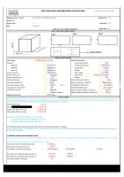
Rectangular Tank Calculation Sheet
TANK CALCULATION SHEET I. DESIGN PARAMETERS: - Code Design
: API 650 & Roark's Formulas Pd : Full water
- Design pressure - Design temperature - Operating pressure - Operating temperature - Corrosion Allowance - Liquid Specific Gravity - Joint Efficiency - Elastic Modulus
MATERIAL SPECIFICATION - Shell, Roof & Bottom - Allowable Stress
= 14.72 kPa : 60 oC / AMB : ATM o : AMB C C.A : 1.5 mm : 0.88 : 0.85 (For Shell) : 0.85 (For Roof & Bottom) E : 2.91*E+7 psi = 200637437 kPa RECTANGULAR : : A-36 Sa : 16600 psi = 114453 kPa : A-106 Gr. B : A-105 : A-234 Gr. WPB : A-193 Gr. B7 / A-194 Gr. 2H : A-36
- Nozzle Neck - Flange - Pipe Fittings - Bolts & Nuts - Stiffeners TANK GEOMETRY: - Height - Length - Width
Height (H)
H: L: W:
Width (W)
Page 1 of 27
1500 mm 1500 mm 1500 mm
Rectangular Tank Calculation Sheet
Page 2 of 27
Rectangular Tank Calculation Sheet II. DESIGN II.1 Side Wall Plate Calculation (Height x Length) II.1.1 Wall Thickness Calculation (As per Roark's Formulas 7th Ed, Table 11.4 Case 1a)
b
b
b
a
a
a
Height (H)
a
b
Stiffeners
Length (L)
Vertical length without reinforced Horizontal length without reinforced Ratio, α β Required thickness tr = Sqrt(β*Pd*b2)/Sa) + C.A
a: b: a/b : = =
750 mm 750 mm 1.00 0.0444 0.2874
= ta :
6.06 mm 8.00 mm
=
2.01 mm
II.1.2 Top Edge Stiffener R1 = 0.03*Pd*a
=
0.33 kN/m
R2 = 0.32*Pd*a
=
3.53 kN/m
Adopted thickness Maximum deflection Ymax = α*Pd*b4/(E*ta3) Ymax
1/2 ta < 2.01mm < 4mm Therefore, adopted thickness is satisfactory
Moment inertia required: Jmin = R1*b4/(192*E*ta)
= = Moment inertia of used stiffener (angle 65x65x8): Jx = Jy =
339.93 mm4 0.0340 cm4 38.285 cm4
Therefore, Top edge stiffener is satisfactory II.1.3 Horizontal Stiffener Moment inertia required: Jmin = R2*b4/(192*E*ta)
= = Moment inertia of used stiffener (angle 65x65x8): Jx = Jy = Therefore, Horizontal stiffener is satisfactory
Page 3 of 27
3625.88 mm4 0.3626 cm4 38.285 cm4
Rectangular Tank Calculation Sheet
Page 4 of 27
Rectangular Tank Calculation Sheet II.1.4 Vertical Stiffener Maximum bending moment at Hy = 0.5773*amax Maximum bending moment: Mmax = 0.0641*Pd*b*Hy2
=
432.98 mm
=
0.13 kNm
= = Section modulus of used stiffener (angle 65x65x8): Z = Therefore, Vertical stiffener is satisfactory
1.16E-06 mm3 1.16 cm3
Required section modulus: Zr = Mmax/Sa
7.96 cm3
II.2 Side Wall Plate Calculation (Height x Width) II.2.1 Wall Thickness Calculation (As per Roark's Formulas 7th Ed, Table 11.4 Case 1a) b
b
b
a
a
a
Height (H)
a
b
Stiffeners
Width (W) Vertical length without reinforced Horizontal length without reinforced Ratio, α β Required thickness tr = Sqrt(β*Pd*b2)/Sa) + C.A
a: b: a/b : = =
750 mm 750 mm 1.00 0.0444 0.2874
= ta :
6.06 mm 8.00 mm
=
2.01 mm
II.2.2 Top Edge Stiffener R1 = 0.03*Pd*a
=
0.33 kN/m
R2 = 0.32*Pd*a
=
3.53 kN/m
Adopted thickness Maximum deflection Ymax = α*Pd*b4/(E*ta3) Ymax
1/2 ta < 2.01mm < 4mm Therefore, adopted thickness is satisfactory
Moment inertia required: Jmin = R1*b4/(192*E*ta)
= = Moment inertia of used stiffener (angle 65x65x8): Jx = Jy = Therefore, Top edge stiffener is satisfactory Page 5 of 27
339.93 mm4 0.0340 cm4 38.285 cm4
Rectangular Tank Calculation Sheet
II.2.3 Horizontal Stiffener Moment inertia required: Jmin = R2*b4/(192*E*ta)
= = Moment inertia of used stiffener (angle 65x65x8): Jx = Jy =
3625.88 mm4 0.3626 cm4 38.285 cm4
Therefore, Horizontal stiffener is satisfactory II.2.4 Vertical Stiffener Maximum bending moment at Hy = 0.5773*amax Maximum bending moment: Mmax = 0.0641*Pd*b*Hy2
=
432.98 mm
=
0.13 kNm
= = Section modulus of used stiffener (angle 65x65x8): Z = Therefore, Vertical stiffener is satisfactory
1.16E-06 mm3 1.16 cm3
Required section modulus: Zr = Mmax/Sa
7.96 cm3
II.3 Roof Plate Calculation b
a
Width (W)
a
b
Stiffeners
Length (L)
Loads on roof plate: - Roof area: - Live load: - Roof weight: - Roof structure weight: - Roof Equipment weight: - Dead load: Total load on roof plate: Distance without reinforced in width Distance without reinforced in length Ratio, α β Required thickness: tr = Sqrt(β*Pd*b2)/Sa) + C.A Adopted thickness Maximum deflection:
= = = = = = =
2.25 m2 1.5 kPa 156 kg 116 kg 100 kg 1.6 kPa 3.1 kPa
a: b: a/b : = =
1500 mm 1500 mm 1.00 0.0444 0.2874
= ta :
5.70 mm 10.00 mm
Page 6 of 27
Rectangular Tank Calculation Sheet Ymax = α*Pd*b4/(E*ta3)
=
Ymax
1/2 ta < 3.5mm < 5mm Therefore, adopted thickness is satisfactory
Page 7 of 27
3.50 mm
Rectangular Tank Calculation Sheet b
b
b
a
a
a
Width (W)
a
II.4 Bottom Plate Calculation b
Stiffeners
Length (L) Distance without reinforced in width Distance without reinforced in length Ratio, α β Required thickness: tr = Sqrt(β*Pd*b2)/Sa) + C.A
a: b: a/b : = =
750.0 mm 750.0 mm 1.00 0.0444 0.2874
= ta :
6.06 mm 8.00 mm
=
2.01 mm
Adopted thickness Maximum deflection: Ymax = α*Pd*b4/(E*ta3) Ymax
1/2 ta
< 2.01mm < 4mm Therefore, adopted thickness is satisfactory
Page 8 of 27
Rectangular Tank Calculation Sheet
Page 9 of 27
Rectangular Tank Calculation Sheet
TANK CALCULATION SHEET I. DESIGN PARAMETERS: - Code Design
: API 650 & Roark's Formulas Pd : Full water
- Design pressure - Design temperature - Operating pressure - Operating temperature - Corrosion Allowance - Liquid Specific Gravity - Joint Efficiency - Elastic Modulus
MATERIAL SPECIFICATION - Shell, Roof & Bottom - Allowable Stress
= 19.62 kPa : 60 oC / AMB : ATM o : AMB C C.A : 1.5 mm : 0.88 : 0.85 (For Shell) : 0.85 (For Roof & Bottom) E : 2.91*E+7 psi = 200637437 kPa RECTANGULAR : : A-36 Sa : 16600 psi = 114453 kPa : A-106 Gr. B : A-105 : A-234 Gr. WPB : A-193 Gr. B7 / A-194 Gr. 2H : A-36
- Nozzle Neck - Flange - Pipe Fittings - Bolts & Nuts - Stiffeners TANK GEOMETRY: - Height - Length - Width
Height (H)
H: L: W:
Width (W)
Page 10 of 27
2000 mm 1000 mm 1000 mm
Rectangular Tank Calculation Sheet
Page 11 of 27
Rectangular Tank Calculation Sheet II. DESIGN II.1 Side Wall Plate Calculation (Height x Length) II.1.1 Wall Thickness Calculation (As per Roark's Formulas 7th Ed, Table 11.4 Case 1a)
b
b
b
a
a
a
Height (H)
a
b
Stiffeners
Length (L)
Vertical length without reinforced Horizontal length without reinforced Ratio, α β Required thickness tr = Sqrt(β*Pd*b2)/Sa) + C.A
a: b: a/b : = =
1000 mm 500 mm 2.00 0.111 0.6102
= ta :
6.61 mm 8.00 mm
=
1.33 mm
II.1.2 Top Edge Stiffener R1 = 0.03*Pd*a
=
0.59 kN/m
R2 = 0.32*Pd*a
=
6.28 kN/m
Adopted thickness Maximum deflection Ymax = α*Pd*b4/(E*ta3) Ymax
1/2 ta < 1.33mm < 4mm Therefore, adopted thickness is satisfactory
Moment inertia required: Jmin = R1*b4/(192*E*ta)
= = Moment inertia of used stiffener (angle 65x65x6): Jx = Jy =
119.37 mm4 0.0119 cm4 38.285 cm4
Therefore, Top edge stiffener is satisfactory II.1.3 Horizontal Stiffener Moment inertia required: Jmin = R2*b4/(192*E*ta)
= = Moment inertia of used stiffener (angle 65x65x6): Jx = Jy =
1273.29 mm4 0.1273 cm4
Therefore, Horizontal stiffener is satisfactory
Page 12 of 27
38.285 cm4
Rectangular Tank Calculation Sheet
Page 13 of 27
Rectangular Tank Calculation Sheet II.1.4 Vertical Stiffener Maximum bending moment at Hy = 0.5773*amax Maximum bending moment: Mmax = 0.0641*Pd*b*Hy2
=
577.30 mm
=
0.21 kNm
= = Section modulus of used stiffener (angle 65x65x6): Z = Therefore, Vertical stiffener is satisfactory
1.83E-06 mm3 1.83 cm3
Required section modulus: Zr = Mmax/Sa
7.96 cm3
II.2 Side Wall Plate Calculation (Height x Width) II.2.1 Wall Thickness Calculation (As per Roark's Formulas 7th Ed, Table 11.4 Case 1a) b
b
b
a
a
a
Height (H)
a
b
Stiffeners
Width (W) Vertical length without reinforced Horizontal length without reinforced Ratio, α β Required thickness tr = Sqrt(β*Pd*b2)/Sa) + C.A
a: b: a/b : = =
1000 mm 500 mm 2.00 0.111 0.6102
= ta :
6.61 mm 8.00 mm
=
1.33 mm
II.2.2 Top Edge Stiffener R1 = 0.03*Pd*a
=
0.59 kN/m
R2 = 0.32*Pd*a
=
6.28 kN/m
Adopted thickness Maximum deflection Ymax = α*Pd*b4/(E*ta3) Ymax
1/2 ta < 1.33mm < 4mm Therefore, adopted thickness is satisfactory
Moment inertia required: Jmin = R1*b4/(192*E*ta)
= = Moment inertia of used stiffener (angle 65x65x6): Jx = Jy = Therefore, Top edge stiffener is satisfactory Page 14 of 27
119.37 mm4 0.0119 cm4 38.285 cm4
Rectangular Tank Calculation Sheet
II.2.3 Horizontal Stiffener Moment inertia required: Jmin = R2*b4/(192*E*ta)
= = Moment inertia of used stiffener (angle 65x65x6): Jx = Jy =
1273.29 mm4 0.1273 cm4 38.285 cm4
Therefore, Horizontal stiffener is satisfactory II.2.4 Vertical Stiffener Maximum bending moment at Hy = 0.5773*amax Maximum bending moment: Mmax = 0.0641*Pd*b*Hy2
=
577.30 mm
=
0.21 kNm
= = Section modulus of used stiffener (angle 65x65x8): Z = Therefore, Vertical stiffener is satisfactory
1.83E-06 mm3 1.83 cm3
Required section modulus: Zr = Mmax/Sa
7.96 cm3
II.3 Roof Plate Calculation b
a
Width (W)
a
b
Stiffeners
Length (L)
Loads on roof plate: - Roof area: - Live load: - Roof weight: - Roof structure weight: - Roof Equipment weight: - Dead load: Total load on roof plate: Distance without reinforced in width Distance without reinforced in length Ratio, α β Required thickness: tr = Sqrt(β*Pd*b2)/Sa) + C.A Adopted thickness Maximum deflection:
= = = = = = =
1 m2 1.5 kPa 97 kg 116 kg 100 kg 3.1 kPa 4.6 kPa
a: b: a/b : = =
1000 mm 1000 mm 1.00 0.0444 0.2874
= ta :
4.89 mm 8.00 mm
Page 15 of 27
Rectangular Tank Calculation Sheet Ymax = α*Pd*b4/(E*ta3)
=
Ymax
1/2 ta < 1.97mm < 4mm Therefore, adopted thickness is satisfactory
Page 16 of 27
1.97 mm
Rectangular Tank Calculation Sheet b
b
b
a
a
a
Width (W)
a
II.4 Bottom Plate Calculation b
Stiffeners
Length (L) Distance without reinforced in width Distance without reinforced in length Ratio, α β Required thickness: tr = Sqrt(β*Pd*b2)/Sa) + C.A
a: b: a/b : = =
500.0 mm 500.0 mm 1.00 0.444 0.2874
= ta :
5.01 mm 10.00 mm
=
2.71 mm
Adopted thickness Maximum deflection: Ymax = α*Pd*b4/(E*ta3) Ymax
1/2 ta
< 2.71mm < 5mm Therefore, adopted thickness is satisfactory
Page 17 of 27
Rectangular Tank Calculation Sheet
Page 18 of 27
Rectangular Tank Calculation Sheet
TANK CALCULATION SHEET I. DESIGN PARAMETERS: - Code Design
: API 650 & Roark's Formulas Pd : Full water + 25 Psig
- Design pressure - Design temperature - Operating pressure - Operating temperature - Corrosion Allowance - Liquid Specific Gravity - Joint Efficiency - Elastic Modulus
MATERIAL SPECIFICATION - Shell, Roof & Bottom - Allowable Stress
= 36.86 kPa : 65.6 oC / AMB : ATM o : AMB C C.A : 1.5 mm : 0.88 : 0.85 (For Shell) : 0.85 (For Roof & Bottom) E : 2.91*E+7 psi = 200637437 kPa RECTANGULAR : : A-36 Sa : 16600 psi = 114453 kPa : A-106 Gr. B : A-105 : A-234 Gr. WPB : A-193 Gr. B7 / A-194 Gr. 2H : A-36
- Nozzle Neck - Flange - Pipe Fittings - Bolts & Nuts - Stiffeners TANK GEOMETRY: - Height - Length - Width
Height (H)
H: L: W:
Width (W)
Page 19 of 27
2000 mm 2000 mm 2000 mm
Rectangular Tank Calculation Sheet
Page 20 of 27
Rectangular Tank Calculation Sheet II. DESIGN II.1 Side Wall Plate Calculation (Height x Length) II.1.1 Wall Thickness Calculation (As per Roark's Formulas 7th Ed, Table 11.4 Case 1a)
b
b
b
a
a
a
Height (H)
a
b
Stiffeners
Length (L)
Vertical length without reinforced Horizontal length without reinforced Ratio, α β Required thickness tr = Sqrt(β*Pd*b2)/Sa) + C.A
a: b: a/b : = =
500 mm 500 mm 1.00 0.0444 0.2874
= ta :
6.31 mm 8.00 mm
=
1.00 mm
II.1.2 Top Edge Stiffener R1 = 0.03*Pd*a
=
0.55 kN/m
R2 = 0.32*Pd*a
=
5.90 kN/m
Adopted thickness Maximum deflection Ymax = α*Pd*b4/(E*ta3) Ymax
1/2 ta < 1mm < 4mm Therefore, adopted thickness is satisfactory
Moment inertia required: Jmin = R1*b4/(192*E*ta)
= = Moment inertia of used stiffener (angle 65x65x8): Jx = Jy =
112.12 mm4 0.0112 cm4 38.285 cm4
Therefore, Top edge stiffener is satisfactory II.1.3 Horizontal Stiffener Moment inertia required: Jmin = R2*b4/(192*E*ta)
= = Moment inertia of used stiffener (angle 65x65x8): Jx = Jy =
1195.93 mm4 0.1196 cm4
Therefore, Horizontal stiffener is satisfactory
Page 21 of 27
38.285 cm4
Rectangular Tank Calculation Sheet
Page 22 of 27
Rectangular Tank Calculation Sheet II.1.4 Vertical Stiffener Maximum bending moment at Hy = 0.5773*amax Maximum bending moment: Mmax = 0.0641*Pd*b*Hy2
=
288.65 mm
=
0.10 kNm
= = Section modulus of used stiffener (angle 65x65x8): Z = Therefore, Vertical stiffener is satisfactory
8.60E-07 mm3 0.86 cm3
Required section modulus: Zr = Mmax/Sa
7.96 cm3
II.2 Side Wall Plate Calculation (Height x Width) II.2.1 Wall Thickness Calculation (As per Roark's Formulas 7th Ed, Table 11.4 Case 1a) b
b
b
a
a
a
Height (H)
a
b
Stiffeners
Width (W) Vertical length without reinforced Horizontal length without reinforced Ratio, α β Required thickness tr = Sqrt(β*Pd*b2)/Sa) + C.A
a: b: a/b : = =
400 mm 400 mm 1.00 0.444 0.2874
= ta :
5.35 mm 10.00 mm
=
2.09 mm
II.2.2 Top Edge Stiffener R1 = 0.03*Pd*a
=
0.44 kN/m
R2 = 0.32*Pd*a
=
4.72 kN/m
Adopted thickness Maximum deflection Ymax = α*Pd*b4/(E*ta3) Ymax
1/2 ta < 2.09mm < 5mm Therefore, adopted thickness is satisfactory
Moment inertia required: Jmin = R1*b4/(192*E*ta)
= = Moment inertia of used stiffener (angle 65x65x8): Jx = Jy = Therefore, Top edge stiffener is satisfactory Page 23 of 27
29.39 mm4 0.0029 cm4 38.285 cm4
Rectangular Tank Calculation Sheet
II.2.3 Horizontal Stiffener Moment inertia required: Jmin = R2*b4/(192*E*ta)
= = Moment inertia of used stiffener (angle 65x65x8): Jx = Jy =
313.51 mm4 0.0314 cm4 38.285 cm4
Therefore, Horizontal stiffener is satisfactory II.2.4 Vertical Stiffener Maximum bending moment at Hy = 0.5773*amax Maximum bending moment: Mmax = 0.0641*Pd*b*Hy2
=
230.92 mm
=
0.05 kNm
= = Section modulus of used stiffener (angle 65x65x8): Z = Therefore, Vertical stiffener is satisfactory
4.40E-07 mm3 0.44 cm3
Required section modulus: Zr = Mmax/Sa
7.96 cm3
II.3 Roof Plate Calculation b
a
Width (W)
a
b
Stiffeners
Length (L)
Loads on roof plate: - Roof area: - Live load: - Roof weight: - Roof structure weight: - Roof Equipment weight: - Dead load: Total load on roof plate: Distance without reinforced in width Distance without reinforced in length Ratio, α β Required thickness: tr = Sqrt(β*Pd*b2)/Sa) + C.A Adopted thickness Maximum deflection:
= = = = = = =
4 m2 1.5 kPa 238 kg 116 kg 100 kg 1.1 kPa 2.6 kPa
a: b: a/b : = =
1000 mm 1000 mm 1.00 0.444 0.2874
= ta :
4.06 mm 12.00 mm
Page 24 of 27
Rectangular Tank Calculation Sheet Ymax = α*Pd*b4/(E*ta3)
=
Ymax
1/2 ta < 3.35mm < 6mm Therefore, adopted thickness is satisfactory
Page 25 of 27
3.35 mm
Rectangular Tank Calculation Sheet II.4 Bottom Plate Calculation b
b
b
a
a
a
Width (W)
a
b
Stiffeners
Length (L) Distance without reinforced in width Distance without reinforced in length Ratio, α β Required thickness: tr = Sqrt(β*Pd*b2)/Sa) + C.A
a: b: a/b : = =
400.0 mm 400.0 mm 1.00 0.444 0.2874
= ta :
5.35 mm 10.00 mm
=
2.09 mm
Adopted thickness Maximum deflection: Ymax = α*Pd*b4/(E*ta3) Ymax
1/2 ta
< 2.09mm < 5mm Therefore, adopted thickness is satisfactory
Page 26 of 27
Rectangular Tank Calculation Sheet
Page 27 of 27