![RT Asme B31 3 2014 [PDF]](https://pdfs.asia/img/200x200/rt-asme-b31-3-2014.jpg)
13 0 693 KB
PT. QUALITA UTAMA
DATE 18-12-2014
PAGE 1 of 20
RADIOGRAPHIC TESTING PROCEDURE SPECIFICATION
DOC. NO. QU/RT/003
REV 02
PT. QUALITA UTAMA RADIOGRAPHIC TESTING PROCEDURE SPECIFICATION In Accordance With ASME BPV Section V – Article 2, 2007 and ASME B31.3, 2004 As Acceptance Criteria
QU/RT/003
THIS AND ALL STANDARD PRACTICE INSTRUCTIONS / OPERATING PROCEDURES CONTAINED IN THE COMPANY QUALITY ASSURANCE SYSTEM ARE CONTROLLED BY THE QUALITY ASSURANCE REPRESENTATIVE AND MAY NOT BE AMENDED, REVISED OR IN ANY ALTERED WITHOUT HIS AUTHORITY. The signatures below indicate, Review and Authorization of all the numbered pages in this Operating Procedures up to and including the date of Authorization. This Procedure is invalid without page 1.
PT. QUALITA UTAMA
DATE 18-12-2014
PAGE 2 of 20
RADIOGRAPHIC TESTING PROCEDURE SPECIFICATION
DOC. NO. QU/RT/003
REV 02
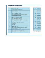
TABLE OF CONTENTS
SECTION NO
TITLE
1.0.
SCOPE
2.0.
REFERENCES AND APPLICABLE CODES
3.0.
PERSONNEL QUALIFICATION & RESPONSIBILITY
4.0.
SAFETY
5.0.
EQUIPMENTS
6.0.
FILM, PROCESSING AND LEAD INTENSIFYING SCREENS
7.0.
SURFACE PREPARATION
8.0.
DETECTION AND PREVENTION OF BACK SCATTERED RADIATION
9.0.
SYSTEM RADIOGRAPHS IDENTIFICATION
10.0.
FILM AND SOURCE PLACEMENT
11.0.
IMAGE QUALITY INDICATOR (IQI) & PLACEMENT
12.0.
SHARPNESS OF RADIOGRAPHIC IMAGE AND SOURCE TO FILM DISTANCE
13.0.
QUALITY AND INTERPRETATION OF RADIOGRAPHS
14.0.
QUALIFICATION OF TESTING PROCEDURE / TECHNIQUE SHEETS
15.0.
EXTENT OF EXAMINATION
16.0.
REPORTING
17.0.
RE – EXAMINATION
18.0.
ACCEPTENCE CRITERIA
Appendix 1
SINGLE WALL RADIOGRAPHIC TECHNIQUE
Appendix 2
EXPOSURE TECHNIQUE FOR FLAT COMPONENTS
Appendix 3
PLACEMENT OF LOCATION MARKERS
Appendix 4
IQI DESIGNATION AND SELECTION
Appendix 5
ASTM WIRE – TYPE PENETRAMETER
Appendix 6
HOLE – TYPE IQI PENETRAMETER
Appendix 7
PERIODIC VERIFICATION CERTIFICATE
1.0
PT. QUALITA UTAMA
DATE 18-12-2014
PAGE 3 of 20
RADIOGRAPHIC TESTING PROCEDURE SPECIFICATION
DOC. NO. QU/RT/003
REV 02
SCOPE 1.1. This testing procedure describes the requirements, technique evaluation and interpretation of radiographic testing on boilers and pressure vessels. 1.2. Specific testing parameter are detailed in the technique sheet.
2.0
3.0
4.0
REFERENCES AND APPLICABLE CODES 2.1
ASME BPV Section V Article 2, 2007
2.2
ASME BPV Section VIII Div 1 and 2, 2007
2.3
ASME BPV B31.3, 2004 Edition
2.4
SHELL DEP 31.38.01.31-GEN
2.5
PT. Qualita Utama’s Company Written Practice No. QU-WP-0 Rev. 0 for NDT Personnel Qualification and Certification.
PERSONNEL QUALIFICATION AND RESPONSIBILITY 3.1
The ASNT NDT RT Level III examiner shall be responsible for the initiation of this procedure.
3.2
Radiographers and interpreters shall be qualified in accordance with the latest edition of PT. Qualita Utama’s written practice No. QU-WP-0 Rev. 0, NDT Personnel Qualification and Certification.
3.3
Radiographers qualified to ASNT NDT RT Level I and under the supervision of the ASNT NDT RT Level II and radiographers qualified to RT Level II may perform radiographic testing
3.4
Minimum ASNT RT Level II may interpret testing under approval of client.
SAFETY All radiographers and assistants shall abide to the safety requirements and rules at all times when performing radiographic work or handling of radio isotopes. This manual formed part of the employment condition for the employees. Client safety procedure shall be followed in addition to the in-house safety manual.
5.0
EQUIPMENT 5.1
Generally the X-ray unit, Ir-192 and Se-75 Gamma ray system shall be used.
5.2
Gamma source unit shall be of the remote (wind-out) type Example Tech-ops model 660 gamma camera. The cameras shall be tested and certified by the manufacturer prior to shipment to the end user. In addition, it is mandatory requirement that these cameras be inspected periodically by the National Atomic Energy (BATAN).
5.3
Small Control Area Radiography ( S.C.A.R ) system with Sentinel model 959 projector including controls, pipe mounting jigs and shield Se-75 source with a maximum of 30
PT. QUALITA UTAMA
DATE 18-12-2014
PAGE 4 of 20
RADIOGRAPHIC TESTING PROCEDURE SPECIFICATION
DOC. NO. QU/RT/003
REV 02
curie strength. 5.4
Source strength of Ir-192 will be 100 curies maximum.
5.5
All personnel radiation safety devices shall be calibrated and in good working condition. Record of dosage and calibration of devices shall be maintained and available for inspection at all times.
5.6
The recommended thickness range (testing limit) for Ir-192 is as follow : Isotope
Steel
Aluminum
Copper or Nickel Alloy
Ir-192
6.0 to 65 mm
3.5 mm and above
5.0 mm and above
Other thickness may be radiographed upon received approval of procedure demonstration by the Authorized Inspector or the Client. 6.0
FILM PROCESSING AND LEAD INTENSIFYING SCREENS. 6.1
Radiographs shall be made using type AGFA D7 or equivalent films or as per Client’s specification..
6.2
All films shall be stored in a clean, dry place where they will not be subjected to : 6.2.1
Chemical vapors
6.2.2
Radiation and light
6.2.3
Excess heat
6.2.4
Undue pressure
If there is any doubt regarding the condition of unexposed film, a film from each box without exposure to light or radiation, shall be processed in the manner used to production radiographs. If this processed films show a density of more than 0.3 H & D the entire box shall be discarded. 6.3 The film processing dark room and all accessories shall be kept the manufacturer. Processing details are stated in the technique sheets attached. Chemical preparation and change out shall follow manufacturer’s recommendations. 6.4 Lead foil intensifying screens of thickness 0.005” (0.13 mm) shall be used to sandwich the film, front and back and placed in leak proof cassettes for exposure. Lead screens to be free of scratches, dust , dirt and moisture which may impair the sensitivity of the film or induced false indication/image on processed films. 7.0
SURFACE PREPARATION Surface of components to be radiographer shall satisfy the requirements of the applicable material and fabrication specification, with additional conditioning, if necessary, by any suitable process to a degree that surface irregularities cannot mask or be confused with discontinuities. All loose foreign particles on the test surface shall be removed.
8.0
9.0
10.0
PT. QUALITA UTAMA
DATE 18-12-2014
PAGE 5 of 20
RADIOGRAPHIC TESTING PROCEDURE SPECIFICATION
DOC. NO. QU/RT/003
REV 02
DETECTION AND PREVENTION OF EXCESSIVE BACK SCATTERED RADIATION 8.1
To check for back scattered radiation, a ½” (13 mm) high lead symbol ‘B’ of thickness 1/16” (1.6 mm) is attached to the back of the film cassette. If a light image of the B appears on a darker background of the radiograph, protection from back scattered is insufficient and the radiograph shall be considered unacceptable. A dark image of the B on a lighter background is not cause of rejection. (ASME VArt.2-T-284)
8.2
Whenever back scattered is evident, a 2 or 3 mm lead sheet or additional layer of intensifying screens will be placed at the back of the film cassette during exposure to shield the film from back scattered radiation.
SYSTEM OF RADIOGRAPHS IDENTIFICATION 9.1
As a minimum, client/contract/project name, component identification , weld seam number, welder number, date and location marker shall be clearly identified on the radiographs by using lead alphabets and lettering.
9.2
The image of these data shall not appear in the image of the area of interest. For flat component or weldment with reinforcement flush to the parent metal, lead arrows or other suitable markers will be used to indicate the area of interest.
FILM AND SOURCE PLACEMENT 10.1 Cassettes with films loaded (sandwiched) shall be securely positioned and intimately close to the surface of the component being radiographer. 10.2 Film overlap of ½” at both ends of the films is required when more than one film are used during single exposure. The effective film length when testing component in flat position can be determined by : L = 0.8 x source to film distance where L is the effective film length 10.3 The main radiation beam to the object and the film shall be as perpendicular as possible to minimize geometric distortion of the radiographic image.
11.0
IMAGE QUALITY INDICATOR (IQI) AND PLACEMENT 11.1 Materials of IQIs IQIs shall be selected from the same alloy material group or grade as identified in ASME SE-1025 or from an alloy material group or grade with less radiation absorption than the material being radiographed. 11.2 Shims under Hole IQIs Shims is applied when use IQI hole type to accommodate weld reinforcement. The material is made similar to the weld metal. It shall be place between the part and the
PT. QUALITA UTAMA
DATE 18-12-2014
PAGE 6 of 20
RADIOGRAPHIC TESTING PROCEDURE SPECIFICATION
DOC. NO. QU/RT/003
REV 02
IQI. The Shim dimensions shall exceed the IQI dimensions and outline of at least three sides of the IQI image shall be visible. 11.3 IQIs / penetrameters shall meet the requirements of ASME V, i.e. wire type (SE-747) or hole type (SE-1025) see T233 Valid for Appendix 2 11.4 One IQI shall be used for 10” x 4” film and two IQI shall be used for 15” x 4” or larger films. 11.5 IQI shall be placed at the least advantage position across the area of interest with thinnest wire facing outward except when using panoramic technique). The identification of the IQI shall not obscure the image of the area of interest. 11.6 Placement of IQIs IQI shall be on the source side of the component being radiographed. If the source side is inaccessible, the IQI may be placed on the film side for which letters ‘F’ shall appear, provided the radiograph’s sensitivity as stipulated in section 13.0 can be achieved. If necessary, procedure qualification can be carried out on a test weld (having same dimensions as the production weld) on which IQI s can be placed on both source and film sides. When the source side IQI achieved the required sensitivity , the smallest corresponding wire discernible on the film used for production radiography. 12.0
SHARPNESS OF RADIOGRAPHIC IMAGE AND SOURCE TO FILM DISTANCE 12.1 Geometric unsharpness (Ug) of radiographs shall not exceed the following :
Material Thickness
Ug. Maximum
Under 2” ( 50.8 mm)
0.02” ( 0.51 mm)
2” through 3” ( 50.8 mm to 76.2 mm)
0.03” ( 0.76 mm)
Over 3” through 4” (76.2 mm to 101.6 mm)
0.04” ( 1.02 mm)
Greater than 4 (101.6 mm)
0.07” ( 1.78 mm)
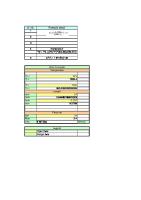
12.2 The geometric unhappiness (Ug) can be determined by : Ft Ug = ------D Where : F
= Source size , the maximum projected dimension of the radiating source (or focal spot) in the plane perpendicular to the distance D from the component being radiographer. D = Source to object distance.
t
13.0
PT. QUALITA UTAMA
DATE 18-12-2014
PAGE 7 of 20
RADIOGRAPHIC TESTING PROCEDURE SPECIFICATION
DOC. NO. QU/RT/003
REV 02
= Thickness of component, assuming the film is intact with the component, plus the space between the film and component. In double wall – double – image technique on piping, the outside diameter shall be considered as it.
QUALITY AND INTERPRETATION OF RADIOGRAPHS 13.1 The transmitted film density through the radiographic image of the IQI and the area of interest shall be 1.8 minimum for single film viewing for radiographs made with an x-ray unit and 2.0 minimum for radiographs made with gamma-ray source. For composite viewing of multiple film exposures, each film of the composite set shall have a minimum density of 1.3 H&D. The maximum density shall be 4.0 H&D for either single or composite viewing. The tolerance for variations in density reading shall be 0.05 H&D. 13.2 If the density of the radiograph anywhere through the area of interest varies by more than minus 15% and plus 30% from the density through the body of the hole type penetrameter and adjacent to the designated wire of a wire type penetrameter, within the required minimum/ maximum density ranges, then an additional penetrameter shall be used. 13.3 The film density shall be determined by calibrated densitometer or stepwedge comparison film verified with a calibrated stepwedge film traceable to a national standard. Calibration of densitometer and Stepwedge comparison strip shall be as described in section T-262 of ASME BPV Section V, Article 2, 2007. 13.4 The required IQI sensitivity for various thickness is stated in the radiographic testing technique sheets attached in this procedure specification. IQI sensitivity shall be calculated base on thinnest visible wire :
i.
ii.
Diameter of Thinnest Wire Visible IQI sensitivity = ------------------------------------------ x 100% Thickness of Component below The diameter of the smallest discernible wire image of the IQI on the parent metal adjacent to the weld-toe-shall be considered.
iii. For double wall double image exposure, that IQI sensitivity shall be computed based on double wall thickness . The IQI sensitivity shall be 3% or better. 13.5 Viewing room for radiographs shall be provided with subdued background lighting of an intensity that will not cause shadow or glare on the radiographs. The viewer shall have minimum 30,000 Lux of Light Intensity to properly illuminate radiographs with H & D density of up 3.5 and adjustment of intensity will be incorporated. 13.6 All radiographs shall be free from mechanical, chemical or other blemishes to the extent that they cannot mask or be confused with the image of any discontinuity in the area of interest in the radiograph, such blemishes include but are not limited to :
14.0
PT. QUALITA UTAMA
DATE 18-12-2014
PAGE 8 of 20
RADIOGRAPHIC TESTING PROCEDURE SPECIFICATION
DOC. NO. QU/RT/003
REV 02
i.
Fogging
ii.
Processing defects such as streaks, water marks or chemical stains.
iii.
Scratches , finger marks, crimps, dirt, static marks, smudges or tears.
iv.
False indications due to defective screens or internal faults.
QUALIFICATION OF TESTING PROCEDURE / TECHNIQUE SHEETS. 14.1 Testing techniques shall be established in a standard format / technique sheets- see attached. 14.2 Each testing technique shall be individually qualified and its parameters recorded. However, qualification test may be waived if the testing techniques have been previously qualified and approved by client. 14.3 Radiographs and testing procedure qualification record sheets shall be maintained and kept on file.
15.0
EXTENT OF EXAMINATION The extent of radiographic examination shall be as per Client or Authorized Inspector request.
16.0
REPORTING 16.1 Interpretation of radiographs shall be reported on the standard radiographic report format (see attached). 16.2 Accompanying the reports, radiographs of each component shall be presented to the client in film folders with all the necessary information including result of interpretation, printed name and signature, recorded on the outside for easy reference. 16.3 A copy of the radiographic report shall be keep and maintained by PT. Qualita Utama for filing and record. 16.4 Client is responsible for maintaining and safekeeping of the reports and radiographs.
K 17.0
RE-EXAMINATION 17.1 An item showing unacceptable defects ,when repaired, shall be re-examined using the same RT technique as originally used.
18.0
ACCEPTANCE CRITERIA 18.1 ASME B31.1 Power Piping – 2007 Paragraph 136.4.5 Welds that are shown by radiography to have any of the following types of discontinuities are unacceptable : a.
Any type of crack or zone of incomplete fusion or penetration
b.
Any other elongated indication which has a length greater than b.1 ¼” (6.0 mm) for t up to ¾” (19.0 mm) b.2 1/3t for t from ¾” (19.0 mm) to 2 ¼” (57 mm), inclusive
PT. QUALITA UTAMA
DATE 18-12-2014
PAGE 9 of 20
RADIOGRAPHIC TESTING PROCEDURE SPECIFICATION
DOC. NO. QU/RT/003
REV 02
b.3 ¾” (19.0 mm) for t over 2 ¼” (57 mm) where t is the thickness of the thinner portion of the weld c.
Any group of indications in line that have an aggregate length greater than t in a length of 12t, except where the distance between the successive indications exceed 6L where L is the longest indication in the group
d.
Porosity in excess of that shown as acceptable in Appendix A-250 of ASME BPV Section I, 2007 Edition and Addenda 2009
e.
Root concavity when there is an abrupt change in density, as indicated on the radiograph.
PT. QUALITA UTAMA
DATE 18-12-2014
PAGE 10 of 20
RADIOGRAPHIC TESTING PROCEDURE SPECIFICATION
DOC. NO. QU/RT/003
REV 02
APPENDIX 1
Single Wall Radiographic Techniques Pipe O.D.
Exposure Technique
Radiograph Viewing
Source-Weld-Film Arrangement End View
Side View
IQI Selection
Placement
Location Marker Placement
Exposure Arrangement ‘A’
FILM
Single Wall T-271.1 Any
Single Wall
Source Side T-277.1(a)
X
X
T-276 and Table T-276
Source centrally placed within circumference. Film(s) wrapped around outside surface.
Film Side T-277.1(b)
Either Side T-275.3 T-275.1(c)
Exposure Arrangement ‘B’ Single Wall T-271.1 Any
X
Source Side T-277.1(a)
X T-276 and Table T-276
Single Wall
Film Side T-275.1 (b)(1) Film Side T-277.1(b)
Source offset internally. FILM Film on opposite outside surface. Exposure Arrangement ‘C’
X
X
Source Side T-277.1(a)
Single Wall T-271.1 Any
Single Wall
FILM
T-276 and Table T-276
Source Side T-275.1 (a)(3)
FILM
Source outside pipe. Film inside on near wall.
Film Side T-277.1(b)
PT. QUALITA UTAMA
DATE 18-12-2014
PAGE 11 of 20
RADIOGRAPHIC TESTING PROCEDURE SPECIFICATION
DOC. NO. QU/RT/003
REV 02
APPENDIX 1 Double Wall Radiographic Techniques (Continued) Pipe O.D.
Exposure Technique
Radiograph Viewing
Source-Weld-Film Arrangement End View
IQI
Side View
Selection
Placement
Location Marker Placement
Exposure Arrangement ‘D’
Any
Double Wall T271.2(a) at Least 3 Exposures 120 to Each Other for Complete Coverage
X X
X X
Single Wall
Source Side T-277.1(a) T-276 and Table T-276
Film Side T-275.1 (b)(1) Film Side T-277.1(b)
Double Wall Single Image Film and source both outside pipe. X-X Optional Source Location Exposure Arrangement ‘E’
Any
Double Wall T271.2(a) at Least 3 Exposures 120 to Each Other for Complete Coverage
X X
X X
Source Side T-277.1(a) T-276 and Table T-276
Single Wall
Film Side T-275.1 (b)(1) Film Side T-277.1(b)
Double Wall Single Image Source and film both outside pipe X-X Optional Source Location Exposure Arrangement ‘F’
X Double Wall T-271.2 3½ in. (b)(1) (88.9mm) at Least 2 or Exposures Less at 90 to Each Other for Complete Coverage
Double Wall (Ellipse): Read Offset Source Side and Film Side Images
X
Source Side T-277.1(a) T-276 and Table T-276
Double Wall Double Image Source and film both outside pipe. Beam offset
Either Side T-275.2
PT. QUALITA UTAMA
DATE 18-12-2014
PAGE 12 of 20
RADIOGRAPHIC TESTING PROCEDURE SPECIFICATION
DOC. NO. QU/RT/003
REV 02
APPENDIX 1 Double Wall Radiographic Techniques (Continued) Pipe O.D.
Exposure Technique
RadioGraph Viewing
Source-Weld-Film Arrangement End View
Side View
IQI Selection
Placement
Location Marker Placement
Exposure Arrangement ‘G’
X Double Wall T-271.2 3½ in. (b)(2) (88.9mm) at Least 3 or Exposures Less at 60 or 120 to Each Other for Complete Coverage
X
Double Wall Read SuperImposed Source Side and Film Side Images
Source Side T-277.1(a) T-276 and Table T-276
Double Wall Double Image Source and film both outside pipe Beam perpendicular to weld and film.
Either Side T-275.2
PT. QUALITA UTAMA
DATE 18-12-2014
PAGE 13 of 20
RADIOGRAPHIC TESTING PROCEDURE SPECIFICATION
DOC. NO. QU/RT/003
REV 02
APPENDIX 2 EXPOSURE TECHNIQUE FOR FLAT COMPONENTS
RADIATION SOURCE
O
RADIATION SOURCE
FILM
O
PT. QUALITA UTAMA
DATE 18-12-2014
PAGE 14 of 20
RADIOGRAPHIC TESTING PROCEDURE SPECIFICATION
DOC. NO. QU/RT/003
REV 02
APPENDIX 3 PLACEMENT OF LOCATION MARKERS
PT. QUALITA UTAMA
DATE 18-12-2014
PAGE 15 of 20
RADIOGRAPHIC TESTING PROCEDURE SPECIFICATION
DOC. NO. QU/RT/003
REV 02
APPENDIX 4 IQI DESIGNATION AND SELECTION
IQI Designation
Table T-233.1 Hole-Type IQI Designation, Thickness, and Hole Diameters, in.( mm ) IQI 1T Hole 2T Hole Thickness Diameter Diameter
4T Hole Diameter
5
0.005 ( 0.13 )
0.010 ( 0.25 )
0.020 ( 0.51 )
0.040 (1.02 )
7
0.0075 ( 0.19 )
0.010 ( 0.25 )
0.020 ( 0.51 )
0.040 ( 1.02 )
10
0.010 ( 0.25 )
0.010 ( 0.25 )
0.020 ( 0.51 )
0.040 ( 10.2 )
12
0.0125 ( 0.32 )
0.0125 ( 0.32 )
0.025 ( 0.64 )
0.050 ( 1.27 )
15
0.015 ( 0.38 )
0.015
( 0.38 )
0.030 ( 0.76 )
0.060 ( 1.52 )
17
0.0175 ( 0.4 )
0.0175 ( 0.44 )
0.035 ( 0.89 )
0.070 ( 1.70 )
20
0.020 ( 0.51 )
0.020
( 0.51 )
0.040 ( 1.02 )
0.080 ( 2.03 )
25
0.025 ( 0.64 )
0.025
( 0.64 )
0.050 ( 1.27 )
0.100 ( 2.54 )
30
0.030 ( 0.67 )
0.030
( 0.76 )
0.060 ( 1.52 )
0.120 ( 3.05 )
35
0.035 ( 0.89 )
0.035
( 0.89 )
0.070 ( 1.78 )
0.140 ( 3.56 )
40
0.040 ( 1.02 )
0.040
( 1.02 )
0.080 ( 2.03 )
0.160 ( 4.06 )
45
0.045 ( 1.14 )
0.045
( 1.14 )
0.090 ( 2.29 )
0.180 ( 4.57 )
50
0.050 ( 1.27 )
0.050
( 1.27 )
0.100 ( 2.54 )
0.200 ( 5.08 )
60
0.060 ( 1.52 )
0.060
( 1.52 )
0.120 ( 3.05 )
0.240 ( 6.10 )
70
0.070 ( 1.78 )
0.070
( 1.78 )
0.140 ( 3.56 )
0.280 ( 7.11 )
80
0.080 ( 2.03 )
0.080
( 2.03 )
0.160 ( 4.06 )
0.320 ( 8.13 )
100
0.100 ( 2.54 )
0.100
( 2.54 )
0.200 ( 5.08 )
0.400 ( 10.1 )
120
0.120 ( 3.05 )
0.120
( 3.05 )
0.240 ( 6.10 )
0.480 ( 12.19 )
140
0.140 ( 3.56 )
0.140
( 3.56 )
0.280 ( 7.11 )
0.560 ( 14.22 )
160
0.160 ( 4.06 )
0.160
( 4.06 )
0.320 ( 8.13 )
0.640 ( 16.26 )
200
0.200 ( 5.08 )
0.200
( 5.08 )
0.400 (10.16 )
…
240
0.240 ( 6.10 )
0.240
( 6.10 )
0.480 ( 12.19 )
…
280
0.280 ( 7.11 )
0.280
( 7.11 )
0.560 ( 14.22 )
…
PT. QUALITA UTAMA
DATE 18-12-2014
PAGE 16 of 20
RADIOGRAPHIC TESTING PROCEDURE SPECIFICATION
DOC. NO. QU/RT/003
REV 02
APPENDIX 4 IQI DESIGNATION AND SELECTION (Continued) Table T-276 IQI Selection IQI Nominal Single-Wall Material Thickness Range, in. ( mm )
Source Side Hole-Type Wire-Type Designation Essential Wire
Film Side Hole-Type Wire-Type Designation Essential Wire
Up to 0.25 (6.4), incl.
12
5
10
4
Over 0.25 (6.4) through 0.375 (9.5)
15
6
12
5
Over 0.375 (9.5) through 0.50 (12.7)
17
7
15
6
Over 0.50 (12.7) through 0.75 (19.0)
20
8
17
7
Over 0.75 (19.0) through 1.00 (25.4)
25
9
20
8
Over 1.00 (25.4) through 1.50 (38.1)
30
10
25
9
Over 1.50 (38.1) through 2.00 (50.8)
35
11
30
10
Over 2.00 (50.8) through 2.50 (63.5)
40
12
35
11
Over 2.50 (63.5) through 4.00 (101.6)
50
13
40
12
Over 4.00 (101.6) through 6.00 (152.4)
60
14
50
13
Over 6.00 (152.4) through 8.00 (203.2)
80
16
60
14
Over 8.00 (203.2) through 10.00 (254.0)
100
17
80
16
Over 10.00 (254.0) through 12.00( 304.8)
120
18
100
17
Over 12.00 ( 304.8) through 16.00(406.4)
160
20
120
18
Over 16.00 (406.4) through 20.00 (508.0)
200
21
160
20
PT. QUALITA UTAMA
DATE 18-12-2014
PAGE 17 of 20
RADIOGRAPHIC TESTING PROCEDURE SPECIFICATION
DOC. NO. QU/RT/003
REV 02
APPENDIX 5 ASTM WIRE-TYPE PENETRAMETER
PT. QUALITA UTAMA
DATE 18-12-2014
PAGE 18 of 20
RADIOGRAPHIC TESTING PROCEDURE SPECIFICATION
DOC. NO. QU/RT/003
REV 02
APPENDIX 6 HOLE-TYPE IQI PENETRAMETER
PT. QUALITA UTAMA
DATE 18-12-2014
PAGE 19 of 20
RADIOGRAPHIC TESTING PROCEDURE SPECIFICATION
DOC. NO. QU/RT/003
REV 02
APPENDIX 7 PERIODIC VERIFICATION CERTIFICATE Step tablet No. : Date of Verification :
Densitometer and No. Series : Date of Expiration :
The density values reported are traceable to NIST and have been verified in accordance with ASME BPV Section V, Article 2 Paragraph T-262, 2007 requirements with results as follow : Step No.
Density Recorded
Actual Density
Deviation
Result
0 1 2 3 4 5 6 7 8 9 10 11 12 13 14 15 16 17 18 The step wedge comparison films is acceptable if the density readings do not vary by more than + 0.05 density units from the density stated on the step wedge comparison films. Verified By,
Name______________ ASNT NDT RT. Level II
PT. QUALITA UTAMA
DATE 18-12-2014
PAGE 20 of 20
RADIOGRAPHIC TESTING PROCEDURE SPECIFICATION
DOC. NO. QU/RT/003
REV 02
APPENDIX 8 RADIOGRAPHY TEST REPORT FORM