![TAIHO Grains Sorter Manual Book [PDF]](https://pdfs.asia/img/200x200/taiho-grains-sorter-manual-book.jpg)
4 0 4 MB
S.PRECISION
PRECISION 6SXZ Series Grains Color Sorter
INSTRUCTION MANUAL
English Version (16.0)
Scope of Application: peanut, Chinese wolfberry, raisin, beans etc. Before Operating This Unit, Please Read These Instructions Completely And Save Them.
Hefei Taihe Optoelectronic Technology Co.,Ltd.
PRECISION 6SXZ Series Grains Color Sorter
Add / Intersection of Yulan Avenue and Fangxing Avenue, Taohua Industrial Park Development Area, Hefei Economic and Technological Development Zone, Anhui, China Tel / +86 551 65399166 Fax / +86 551 65399188
Pc / 230601
Exporting Department / +86 551 65399015
E-mail / thsorter@colorsort .cn Http / www.chinacolorsort.com Client Service Center / 400 660 9996 After Sale Service Tel / +86 551 68588368(OVERSEAS)
E-mail / service@colorsort .cn
Hefei Taihe Optoelectronic Technology Co. , Ltd.
6SXZ series Grains cereals color sorter
PRECISION 6SXZ Series Grains Color Sorter
INSTRUCTION MANUAL
English Version (16.0)
Hefei Taihe Optoelectronic Technology Co. , Ltd.
6SXZ series Grains cereals color sorter
6SXZ series Grains cereals color sorter
Contents
User Guide Thanks for choosing the 6SXZ series Grains color sorter of our company! With twice sorting function, 6SXZ series CCD Grains color sorter integrates such new and high-techs as optics, mechanics, electricity, and pneumatics. With the basic working principle being “feeding by feeder”, the color sorter sends materials through the observation window, and CCD camera collects color and shape information about the material and send data to the data treatment unit that will conduct image treatment and threshold judging, finally, the sorter will remove imperfect materials by the high frequency solenoid valve. The product adopts the high-speed, high-sensitivity linear CCD array with resolution ratio 4096Pixel as the color and shape sensor. Using SOC-based platform architecture, compared to DSP platform, CPU frequency increased 5 times, 4 times the output processing capacity to achieve stable and reliable, ultra-high-speed mass data processing, making the product in the minimum resolution, color accuracy, Select efficiency and other aspects of performance is better than the same type of color selection machine.
User Guide
I
Chapter I Safety Cautions and Warning Signs
01
Chapter II Machine Structure
03
Chapter III Installation Method
04
Chapter IV Operation Instructions and Adjustment Means
07
Chapter V Maintenance and Upkeeping
29
Chapter VI Common Faults and Solutions
30
Chapter VII Electrical Wiring Diagram
33
Chapter VII List of Accessories, Fittings and Wearing Parts I
38
Chapter IX Warranty Card
40
1. The manual gives a detailed account of performance, parameter setting and operational approach of the 6SXZ series Grains color sorter. 2. Please read the manual carefully before using, and operate strictly in accordance with the operation specification specified in the manual. Use products correctly, please pay special attention to the safety notes. 3. It is necessary to use parts provided by our company in maintenance, and our company shall be free of any liabilities for consequences if any failures and accidents resulted by user using parts not provided by us. 4. The product should be installed in a well-ventilated workplace, kept away from the environment with low or high temperature, high humidity, dust and high magnetism. 5.
The product is applicable to the final processing procedure to ensure the color separation.
6. As the unceasing development and improvement of technology, technical updates and manual changes would be subject to the product updates without any advance notification, please pay close attention to the product update information in time, which will be shown in our website(http://www.chinacolorsort.com).
Hefei Taihe Optoelectronic Technology, Co., Ltd. Address: Intersection of Yulan Avenue and Fangxing Avenue, Taohua Industrial Park Development Area, Hefei Economic and Technological Development Zone, Anhui, China Post Code: 230601 Sales Tel: +86 551-65399166 Fax: +86 551-65399188
http://www.chinacolorsort.com
6SXZ series Grains cereals color sorter
Chapter I Safety Cautions and Warning Signs
1.1 Safety Cautions Unpack to check the product and watch out the safety. In unpacking, avoid causing any damage to the product, and keep well it after checking quantity of parts according to the list inside the box. In installing, check carefully the reliability of the sling for hoisting the color sorter. The product should be kept away from work place with strong magnetism, strong sunshine and dusts. Safety grounding connection for the color sorter: the input power is required with good ground connection (if not, making grounding device as shown in the following picture is recommended). Methods for making grounding wire: galvanized welding, with the soldering point covered by asphalt, as shown in the following picture.
30cm natural soil Repeatedlyfill in accordance with the following three filling ways and sequence.
10cm charcoal
A layer of crude salt 30cm natural soil
Figure 1-1 Grounding Wire Making Diagram
To prevent static electricity, the feeding pipe, discharging pipe and exhaust pipe prepared by users shall be iron pipes rather than the plastic and other non-metal pipes. Air compressors and other equipments prepared by users shall comply with relevant national laws and regulations and standards. The incoming end of power used by users shall comply with national safety standard and be installed with dustproof device to keep it away from dust.
01
6SXZ series Grains cereals color sorter
6SXZ series Grains cereals color sorter
Chapter II Machine Structure
1.2 Statements of Safety Warning Signs Signs
Meaning
Signs
Meaning
2.1 Major Mechanical Structure 2.1.1 Feeding device
2-dimensional bar code, just scan it to connect company website,knows the latest info
Dangerous, Beware Of Electricity
The feeding device installed on the feeder beam is composed of the feed hopper, feeder and receiving hopper, the selected material will be conveyed via the feed port to the chute. The combination of damping spring and the device effectively reduce the resonance.
2.1.2 Chute
No welding, please make sure there is no any welding works near the machine
No drilling, please make sure there is no any drilling on the machine.
The material chute is composed of multiple-unit ramp ways and trims strips, which can enable the selected materials evenly passing the observation zone of the sorting cabinet. This area or object will be over heating
2.1.3 Sorting cabinet The sorting cabinet is composed of light source, background regulating device, sensor, and observation window and the dustproof device. In operation, it can send the collected image data to the data treatment center for image treatment as preset. Dustproof device deash automatically and regularly, thus preventing the dust interference.
Please follow the instructions
2.1.4 Ejector In receiving the executive instruction, the high frequency ejector will properly spray the compressed gas to remove the defective products.
2.1.5 Discharge hopper
Grounding position
Please turn off the power before you open the door of electrical control cabinet
The hopper includes the front and rear discharge hoppers, respectively receiving the finished products and defective products. Note: The dust collector device shall be installed to prevent dust from entering the sealed cavity; or the service life and color separation function of the machine will be directly affected.
2.1.6 Electrical control cabinet A completely-enclosed unit in which the system power and master control board is installed. Up limit of the air pressure
USE 220V AC
2.1.7 Air supply system The system, located at the rear of the machine, is equipped with filter valve, distribution valve and the pressure regulating valve and can provide the machine with high cleanness compressed air. In addition, with the node type pressure gauge, the system will automatically alarm and remind users of the pressure faults on the display if the air pressure in the ejector is lower than the setting pressure.
2.1.8 Heating system Dangerous, Beware Of Electricity
The device, located at the reverse side of material chute, is controlled by a high reliability automatic temperature regulating system, which enables the temperature of material chute approaching to that of the selected material, thus preventing the material flying.
2.1.9 Body Body structure falls within the enclosed type by the combination of the rack and steel plate.
02
03
6SXZ series Grains cereals color sorter
6SXZ series Grains cereals color sorter
Chapter III Installation Method Note: The color sorter shall be installed under the guidance of the service engineer of our company.
Align the aggregate bin of the color sorter to users' feeding pipe which should be equipped with flow control plate and storage bin and not press on the aggregate bin, or color sorter's working efficiency will be affected.
3.1 Installation conditions for the machine
Note: personal injury or mechanical faults would be caused by improper installation position.
3.1.1 Site requirements The installation site should be flat and solid, and the constructed working platform should be away from strong vibration sources like the polishing machine and white rice grader. The elevator should be installed before installing the color sorter so as to prevent damage to the color sorter caused by the falling welding or hard objects. The installation site for compressor and air tank should be away from the crowd so as to reduce noise pollution or other possible injury. Also, users are recommended to keep the compressor and air tank in ventilated and dry place, thus keeping the compressed air clean and dry.
3.1.2 Environmental requirement Like the common domestic appliances, in term of ambient temperature, the color sorter is required to be 0℃~ 40℃,so it is recommended to construct AC room in areas with high temperature and greenhouse in areas with low temperature.
3.3 Accessory installation It is strong recommended for users to use iron pipe as the material pipe rather than the PVC or other materials that would cause triboelectrification.
3.3.1 Feeder installation The feeder placed in the accessory box should be mounted on the feeder bedplate in accordance with the serial number. It is required to prevent the feeder from slipping down which may cause personal injury or damage to the color sorter chute.
3.3.2 Aggregate bin installation User should construct a self-made aggregate bin based on the design drawing provided by our company, and the aggregate bin requires an observation window for real time observation of the amount of material stored in the hopper. Lifting rope or rack can be used in installing the aggregate bin to prevent color sorter from bearing the weight of the bin.
3.1.3 Light requirement As the external light will directly affect the color separation, it is necessary to keep the color sorter away from strong light and forbidden to put a ceiling lamp above it. Enough lighting, of course, is necessary for the operation and maintenance.
3.3.3 Elevator installation Discharge pipe of elevator must be installed right above the center of the aggregate bin, thus ensuring sufficient materials for feeders on sides of color sorter.
3.1.4 Maintenance space Enough space around the color sorter is necessary for debugging and maintenance, and the recommended space around the sorter is above 60cm.
3.3.4 Discharge pipe installation The included angle between the discharge pipe and ground should be more than 30 degrees so as to prevent the material from blocking the discharge pipe.
3.1.5 Ground wire requirement As grounding the sorter can avoid the lightning strokedamage to the machine or any personal damage due to current leakage which resulted by misoperation, users are recommended to embed ground wire before welding the platform. To prevent interference, individual wire with ground resistance no more than 4or the color sorter.
Air compressor (customer-provided) power should be three-phase AC 380V±10%, with frequency 50Hz±1%.
3.2 Installing color sorter
The power supply for color sorter should be single phase AC 220V±10% and with frequency 50Hz±1%. The power provided should also comply with relevant national standards and the operating instruction.
Before installation, the user should, in accordance with the equipment platform size drawings, construct the color sorter working platform, with platform elevation about 1.5m, and platform firmly and levelly welded. As the color sorter is the precision equipment, any mechanical deformation resulted by vibration must be avoided in carrying. Customers are strong recommended to transport with forklift or crane. If crowbar is used as conditions not permitting, the cushion wood used in carrying should not be removed until the color sorter is moved nearby theplatform, then place the sorter on the platform by the hoist type crane or other ways. After which, adjust the levelness of the equipment within 2mm/1000mm by the leveling instrument.
04
3.4 Electric installation 3.4.1 Power supply
3.4.2 Safety requirements for electric installation The incoming end of the color sorter power supply should be equipped with air switch above 20A (Not using knife of switch). In order to prevent personal injury caused by leakage of electricity, lightning stroke or static electricity, users are required to set up excellent grounding system.
05
6SXZ series Grains cereals color sorter
3.5 Requirements for air circuit installation
6SXZ series Grains cereals color sorter
Chapter IV Operation Instructions and Adjustment Means
The oil and water free air compressor should be used along with the air filter. The Dg25mm galvanized pipe or pipes with higher grades (e.g. PPR pipe) must be used to connect components of the gas circuit. The installation position of the air compressor should be subject to the proximity principle, with the pipe total length no more than 20m, and it is recommended to install the air compressor in an isolation room nearby the color sorter (15m distance is ideal).
4.1 Operation
3.6 Dust collecting pipe installation
In order to achieve the performance of the manchine, references as follows are provided for you:
The user should equip with dust collecting pipe to prevent dust from depositing in the sealed cavity which will affect the light-colored material separation
3.7 Other instruction
The parameters of the machine, which has been adjusted to qualify the factory standard, may be affected by the mechanical handling and vibratory transport, our engineer will make further debugging according to the user’s materials , after which, it is forbidden to dismantle and repair the machine by others,otherwise wrongly adjusting the machine will affect its normal operation, or even reduce its life time. (1)Adjust correctly the reference background (i.e. the background plate position). (2)The proper sensitivity, which can help achieve performance of the machine, the user should know the higher sensitivity doesn't equal to the better result.
(1)Power of air compressor: (7.5~37)kW
4.1.1 Preparations before operation
(2)Air supply pressure: (0.5~0.8)MPa
(1)Check if any foreign material is in the feed hopper. If any, remove them.
(3)Operating temperature: (+0~+40)℃ (4)Operating relative humidity: ≤80﹪
3.8 Drawing
(2)Start the air compressor and wait till its pressure reaches to 0.8MPa. Note: once starting the air compressor, effluent in it should be emptied as the pressure regulating valve would be frozen in winter, which will cause the air obstruction, because of the undischarged water. If so, the heating source (=45℃)can be used instead of frequent adjustment of the pressure regulating valve, for which may damage accessories inside it.
We have provided users with drawings concerning all types of machine, please select corresponding installation drawings according to the type you ordered. Users should design the working platform and aggregate bin in accordance with the equipment platform size drawing, aggregate bin size drawing provided by our company, and install relevant parts in accordance with the material flow diagram and gas circuit equipment installation diagram.
Figure 4-1 Air circuit diagram of PRECISION rices color sorter
( 3) Check as shown in diagram 4-1, with manifold pressure gauge setting at 0.8MPa, working pressure gauge at 0.3MPa. If working pressure fails to reach the setting value, the machine will be unable to work and the low pressure warning will be indicated on the display. (4)Check if any leakage about the gas circuit and if any, tighten the connector at the air leakage point. It is normal to have slight air flow of the snifting valve and inside pipes.
06
07
6SXZ series Grains cereals color sorter
6SXZ series Grains cereals color sorter
(5)Check if any sundries or rice bran on the tray above the feeder, and on the glass surface of the material. Chute and separation cabinet or on the top of the material chute. If any, ash remover or soft cloth rather than hard articles can be used to remove them.
Note: hard articles, which will badly scratch the chute surface and effect the color separation, shall not be allowed to rub the material chute. Ash remover or soft cloth will be ideal.
4.1.2 Startup flow (1)Power on: press the black button to power on the machine, and the system will execute self-checking 2~3min. ( 2) System preheating: the system will determine weather to be preheating according to the ambient temperature, if required, the system will preheat 5~10 min. ( 3) Select the color sorting mode you need, and the color sorting mode selection, if the same with the previous one, you can pass by this. ( 4) Start color sorting: click on button of the display, the color sorter begins to discharge material and sorting. ( 5) Based on the raw material, to adjust the background , feeder spead rate and sorting accuracy. The sensitivity setting depends on the materials selected, if meeting the requirement, the lower sensitivity is better, for example, it is unnecessary to adjust the sensitivity value to 70% if 60% of it meets the color sort requirement.
4.1.3 Shutdown flow
Figure 4-2 Welcoming interface
System languages can be selected through the welcome interface, including Chinese, English, etc. If the settings are saved after the system starts, the selected language will be directly applied for the next time, or the language which is saved last time is used for next time.
4.2.2 Self-detection Interface
Note: please follow the shutdown sequence, and forced power off under the working condition is not be allowed. (1)Click on the button to stop color sort. wait 3s, and then press the black button on the panel, if parameter is changed and not to be saved, system will give, a tip to save parameters ,the system will save parameters if confirm to save, or directly power off. (2)Remove dusts on the machine. (3)Check if sewage is removed by filter automatic drainage on pipelines, and open the sewage outlet at the bottom of the air compressor to discharge all sewage. Note: the power supply of the machine should be cut off before maintenance.
4.2 Operation and setting The system operation interface mainly consists of a welcome interface, a self-detection interface, a main interface, an interface of user settings, and an interface of advanced settings.
4.2.1 Welcoming interface
Figure 4-3 Self-detection Interface
08
09
6SXZ series Grains cereals color sorter
6SXZ series Grains cereals color sorter
The self-detection interface of the system detects the state of the system when the system starts and shows the results of self-detection, mainly including communicating state, camera state, temperature control state and gas circuit state. If any detection item is abnormal, “abnormal” will be displayed on the screen, and this interface will be maintained after detection ends; if all detection items are normal, “normal” will be displayed on the screen, and the system will automatically skip to the main interface after two seconds.
(4) Starting and shutting down system: When the system is shut down, the switch button is gray; click the handle, the system begins to clear dust; when dust clearing ends, the system selects color according to the current parameters set by the user, and at the moment, the button is green. When thesystem is started, the switch handle is green; click the switch handle, the system shuts down and stops color selection, and at the moment, the button color turns to gray.
4.2.3 Main Interface
4.2.4 Interface of System Settings
Figure 4-4 Main Operation Interface Figure 4-5 Interface of system settings
The main interface has the functions of starting and closing the system, and displaying the sensitivity button, the color selection plan button, the feeing amount button, etc. Click the icon, the system can skip to the corresponding adjustment interface, so it is convenient to promptly adjust relevant parameters of machines.
The interface of system settings is mainly used for skipping to other interfaces. It includes sub-interfaces of language selection, administrator settings, signal settings, spray valve settings and image acquisition.
(1) Color selection plan:
Click icons to enter into corresponding sub-interfaces.
Click the color selection plan button, the system can directly skip to the interface for setting color selection plans. On this interface, the user can save current plan, or save the current parameters as any other plan, or read parameters of other plans and enable another plan to become the current plan. (Note, the plan cannot be adjusted in the starting state.)
The bottom of the interface of system settings is toolbar (as shown in figure 4-6). Toolbar is shown at the bottom of each interface, which provides convenience for realization of start and shutdown of the system, dust clearing, start and shutdown of the feeding machine, start and shutdown of the spray valve, and functions of spray valve indication and sensitivity.
The current color selection plan shows types and detailed plans, wherein the plans are classified in five types; twenty detailed plans can be saved for each type. The user can access plans at will. (2) Feeding amount: Click the feeding amount button, the system can directly skip to the feeding-amount adjustment interface. On this interface, the vibration quantity of each channel can be adjusted independently. The discharging amount of each feeding machine can be displayed. (3) Sensitivity: Click the sensitivity button, the system can directly skip to the sensitivity adjustment interface. On the sensitivity interface, the sensitivity data can be accurately adjusted in various ways. The sensitivity of the current trough can be displayed, including thresholds of front and back view, upper and lower limitation, and spot impurities/region impurities. Click advance button, first/second is displayed on the screen. Clicking the edit box under the trough, the user can adjust the current trough.
10
Figure 4-6 Toolbar Click the dust clearing button ,f the system is started, the system will directly clear dust after shutting down the spray valve and the feeding machine, or the system will directly clear dust according to the set time.
Click the spray valve button and shutdown. Click the feeding machine button start and shutdown. Click other buttons interfaces.
,the state of the spray valve will be switched between start ,the state of the feeding machine will be switched between the system will directly skip to corresponding
11
6SXZ series Grains cereals color sorter
4.2.5 Language Switch Interface
6SXZ series Grains cereals color sorter
4.2.7 Interface of Light Settings
Figure 4-7 Language switch interface On the language switch interface, the language display interfaces of relevant systems can be switched. The default languages include Chinese and English.
4.2.6 Interface of Administrator Settings
Figure4-9 Interface of light settings Click the signal setting icon on the interface of system settings. After the icon skips to the inside, select the light button at the left upper corner to enter into the interface of light settings. Front main lamps and rear main lamps indicate four main lamps for front and rear sorting tanks. RGB indicates background light. The color with the largest value is the current color for the background board. The background setting interface is mainly used for setting the front view background and the rear view background. The background strength is adjusted to be similar to the signal strength of normal material and largely different from flaw signals. Then flawed material can be removed by removing signals which are stronger or weaker than normal material. The adjustment of background is generally made when the machine is shut down. In addition, front and back view backgrounds should be set separately. The adjustment range of all lamps is 0~255.
4.2.8 Camera Gain
Figure 4-8 Interface of administrator settings The Interface of administrator settings is used as a testing and debugging interface for professionals of the manufacturer during production, quality inspection and after-sales service. It is recommended not to operate for users. Wrong operation may result in abnormality of the system. Figure 4-10 Interface of camera gain
12
13
6SXZ series Grains cereals color sorter
6SXZ series Grains cereals color sorter
Click the middle camera gain button at the right upper corner on the interface of signal settings, the system will automatically skip to the interface of camera gain. The main purpose of the interface of camera gain is to adjust the gain of cameras. The following is the general principle for adjusting camera gain: In the single selection of minimum value, the signal of normal material can be varied between 192 and 244. In the simultaneous usage of minimum value and maximum value, the signal of normal material can be varied between 128 and 160. Therefore, a larger dynamic range can be ensured (Note, it is signal of normal material, rather than background signal). Each trough is equipped with two cameras (including a front view camera and a rear view camera). When the camera gain is adjusted, the front view camera and the rear view camera are separately adjusted.
4.2.9 Optical Calibration Click the rightmost optical calibration button at the left upper corner on the interface of signal settings, the system will automatically skip to the optical calibration interface. The optical calibration interface is mainly used for completing the calibration of optical systems, monitoring the adjustment of camera positions and monitoring the condition of data paths.
Figure 4-11 optical calibration interface
Clicking the optical calibration button, the user can perform optical calibration on each trough. Each trough needs independent calibration. The following is the steps of calibration: firstly, put a white balance target on the corresponding channel; then, observe whether signals are normal through the waveform window; signals at all positions on the channel can be observed through mobile selection; if signals have no outstanding bright or dark points and generally present the shape of flat bell, the signals are abnormal, the user can click the calibration button to perform calibration (front and rear views can be simultaneously calibrated, so independent calibration is unnecessary). Monitoring of camera position adjustment is to assist the adjustment of camera positions. Firstly, select the right middle camera adjustment, and put on the calibration target; at the moment, observe whether the bell shape of signal waveform is sharp enough, namely is close to the shape of rectangle, otherwise, it is necessary to adjust the focal length to make the waveform sharp enough; then observe whether signals of the camera overlap with corresponding standard line, if completely overlap, it means the camera position is appropriate, and the camera can be positioned. The monitoring of conditions of the data path is to check whether the data path is normal. From original data, the user can see data from cameras. From calibration data, the user can see data calibrated by the system. From test data, the user can see linear test data from cameras.
Figure4-12Interface for setting dust clearing valve
4.2.11 Setting of ejecting valve
4.2.10 Interface for setting dust clearing valve Click the spray valve setting icon on the interface of system settings, the system will skip to the inside. Select the dust clearing valve at the left upper corner, enter into the interface for setting dust clearing valve. The interface for setting dust clearing valve is mainly used for setting dust clearing time. This interface has the functions of setting dust clearing time and dust clearing cycle, and displaying dust clearing cycle. The dust clearing time is 5-10 seconds in general. The dust clearing cycle is about 30 minutes in general. The time and cycle are adjusted appropriately according to dust amount of selected material. To protect the spray valve, please shut down the spray valve prior to selecting dust clearing. Go dust clearing/Return dust clearing means one-way action. If click “Go dust clearing” on the machine screen, the dust clearing brush clamp brushes across one side, and does not come back. Then, click “Return dust clearing”, the dust clearing brush clamp will return from the other side. Figure 4-13 Interface for setting ejecting valve
14
15
6SXZ series Grains cereals color sorter
6SXZ series Grains cereals color sorter
Click the spray valve setting icon on the interface of system settings, the system will skip to inside. Select the ejecting valve at the left upper corner, and enter into the interface for setting the ejecting valve.
The system information interface is mainly used for reviewing the state information of the system, mainly including the communication quality, software version, information records, statistics of working frequency of spray valves, and detection information in startup. The communication quality interface shows the communication state of the system, mainly including the display board, the control board and the LED board. Communication quality is divided into a transmission part and a reception part. Under normal state, the number is 0; the larger the number is, the poorer the communication quality is. When the number is larger than 128, the communication system can only perform reception, cannot perform transmission. When the number is 255, thecommunication is completely lost.
The dialogbox for spray valve test is the first row on the ejecting valve interface. The spray valve test is mainly used for detecting whether the spray valve is normal. Click the upper part of the dialogbox for spray valve test to select trough; then, click channel n to input the position of the spray valve to be detected, and the position of the spray valve to be detected can also be adjusted by increasing and increasing buttons. Channel data indicate the position of the current tested spray valve; when the repeat button is in the repeatedly open state, the channel repeatedly tests the spray valve in the frequency of three times per second. When the high-frequency button is in the high-frequency open state, the spray valve is tested 15 times as the spray valve acts once. The auto test button is used to test spray valves of all channels of all troughs The interface for setting removal time is used to set blowing time, delay time, the starting time of spray valves, and the compound modes of valves. The delay time is the time during which the system finds the flawed material and the flawed material falls to the position of the blowing nozzle. The blowing time is how long the high-frequency gas flow sprayed out from the nozzle will last every time. The system divides the blowing time and the delay time for spot impurities and regional impurities. The starting time of the spray valve is the time taken to start the spray valve after the valve receives the instruction every time.
Click the refresh button, the user can read the communication state again.
The compound modes of valves include independent blowing, additional left blowing, additional right blowing, and both left and right blowing. Independent blowing indicates single spray valve blows; additional left blowing indicates while the current spray valve blows, one valve on the left of the spray valve also blows; additional right blowing indicates while the current valve blows, one spray valve on the right also blows; the above two modes indicate there are two spray valves spraying together; both left and right blowing indicates while the current spray valve blows, the left spray valve and the right spray valve blow together.
4.2.12 System information interface Figure 4-15 Software version sub-interface 1 of system information
Figure 4-14 Communication quality sub-interface of system information Figure 4-16 Software version sub-interface 2 of system information
16
17
6SXZ series Grains cereals color sorter
The software version interface mainly shows the version information of display boards, control boards, converter boards, LED boards and troughs.
Figure 4-17 Information record sub-interface of system information
The information record interface mainly gives the automatic shutdown times under high and low pressure, time, voltage, accumulated working time of the machine, and the current working time.
6SXZ series Grains cereals color sorter
The electromagnetic valve working statistics interface mainly offers the real-time operation and times of each spray valve on the corresponding trough, namely the blowing times of the spray valve.
Figure 4-19 Detection information sub-interface of system information
The detection information sub-interface of system information mainly records the information regarding the automatic detection of the system when the system starts.
4.2.13 Image acquisition interface The image acquisition interface mainly realizes the image acquisition for the selected material.Materials are compared on the display screen, and the sense value is set with reference to the current acquired image to correctly remove material in poor quality.
Figure 4-18 Electromagnetic valve working statistics sub-interface of system information
Figure 4-20 Image acquisition interface
18
19
6SXZ series Grains cereals color sorter
4.2.14 Color selection plan interface Click the color selection plan on the system interface, the system will directly skip to the color selection plan interface. The color selection plan interface mainly realizes the storage and access of color selection plans, and plan configuration.
6SXZ series Grains cereals color sorter
The plan configuration interface is mainly used for determining the minimum and maximum of spots and regions, the color sensitivity or shape selection and figure selection according to color selection materials. Please note, when shape selection is used, there should be corresponding shape selection documents in the right drop-down box for shape selection, otherwise, the function of shape selection cannot be used. Note: the selection of same setting of front view and rear view is on the right of the interface, which indicates when you set the color selection attribute in front view or rear view, corresponding rear view or front view also is set simultaneously.
Figure 4-21 Color selection plan setting interface
The color selection plan interface mainly provides 5 plans for the user. The current plan displays the current kind (type) and the detailed plan of the system. The plan window is mainly used for completing the saving of new plans and the access of old plans. The plan can be independently made according to material by selecting the reference plan on the left or clicking the additional plan at the left lower corner.
Figure 4-22 Color selection configuration interface
20
Figure 4-23 Plan reading interface
Select the right reference plan or the previously used old plan, and click the usage button, at the moment, a dialog box will pop up, indicating whether to read parameters of the mode. Click “Yes” to read the plan, or click “No” to cancel.
Figure 4-24 Plan saving interface
21
6SXZ series Grains cereals color sorter
6SXZ series Grains cereals color sorter
When the new plan needs to be saved or parameters are changed, click the “save” button or directly click “save as”, at the moment, a dialog box will pop up to input the name of the plan to be saved; then, click “Yes” to directly save the plan in the current plan. The prompt system can automatically extract the current time as the saving time of the mode.
4.2.15 Feeding machine interface
Figure 4-26 Sensitivity interface
1 The gray-level sensitivity interface
Figure 4-25 Feeding machine setting interface
The feeding amount interface mainly realizes the adjustment of feeding amount, start and shutdown of the feeding machine. The adjustment range of the feeding amount is 1-99. When the feeding machine button on the toolbar shows “feeding machine shutdown”, the feeding machine will not feed materials regardless of the feeding amount of upper part and the state of the switch of the feeding machine. When the feeding machine button on the toolbar shows “feeding machine start”, the open state of the feeding machine with single channel can be controlled through the upper vibrator switch. In the dialog box of vibrator settings, for the adjustment of the vibration frequency, the vibration frequency should be consistent with the frequency marked on the vibrator, otherwise, the normal operation of the vibrator cannot be guaranteed.
4.2.16 Sensitivity interface The sensitivity interface mainly includes gray-level sensitivity interface, chroma sensitivity interface, and colordifference sensitivity interface. The user can use gray-level sensitivity interface, chroma sensitivity interface, and color-difference sensitivity interface independently or compositely.
22
Figure 4-27 Sensitivity sub-interface
The graph 4-27 shows the gray-level sensitivity interface. It is mainly used to adjust the degree of sensitivity of each material groove, or to make a unified adjustment to all the material grooves on the main interface of the sensitivity. The types of sensitivity mainly include spot and area, once and twice, foresight and backsight, upper limit and lower limit, and dimension setting. Dimension setting mainly sets the corresponding data according to the shapes of the materials.
23
6SXZ series Grains cereals color sorter
2 Color –level sensitivity interface
6SXZ series Grains cereals color sorter
3 Shape-selecting sensitivity interface Click the button of Shape-selecting, and directly shift to the shape-selecting sensitivity interface. At present the shape-selecting function mainly includes to choose length, area, and roughness. Using what kind of shapeselecting procedure relies on the selected materials. As shown in figure 4_28 the interface is normal standard shape-selection. Of course according to the difference of the procedure of system document you select, the shape-selecting interface is different. But the most common shape-selecting interface generally includes the option about length and area. Note: check shape option and select the shape selection file needed by color selection material at the drop-down bar of shape option when you select the shape option and allocate the scheme, and then click the application button.
Figure 4-28 Color Sensitivity Interface
Color –level sensitivity interface mainly completes the settings of chromatic parameters, majorly including the state of chromatic selection, the types of chromatic use, intensity control, and dimension settings etc. The state of chromatic selection can use or be forbidden to use foresight and backsight.The types of chromatic use needs to be done in the solute on configuration of color-selecting project, mainly including the three types, red-green chromatic aberration, red-blue chromatic aberration, and green-blue chromatic aberration. Red-green chromatic aberration is mainly applied for the flawed materials which selects the color between red and green. Red-blue chromatic aberration is mainly applied for the flawed materials which selects the color between red and blue. Green-blue chromatic aberration is mainly applied for the flawed materials which selects the color between green and blue. In generally only one type can be used to select color, and at most two types can be used to select color at the same time. As long as it is determined by the color-selecting materials, brightness limit will decide the range of color-selecting.
Picture 4_29 Shape-selecting sensitivity interface
4 Image-selecting sensitivity interface
Dimension settings mainly rely on the shapes of the materials to set corresponding data. Sensitivity of color difference is mainly used to adjust the digital increase of the red, of the green and of the blue. Color differences of the red and the green correspond to increase of red number. Color differences of the red and the blue correspond to increase of green number. Color differences of the blue and the green correspond to increase of green number. If the radio button is red, not green, which means the red one is defective material, if the radio button is green, not red, which means the green one is defective material. If the radio button is red, not blue, which means the red one is defective material, if the radio button is blue, not red, which means the blue one is defective material. If the radio button is blue, not green, which means the blue one is defective material, if the radio button is green, not blue, which means the blue one is defective material. Color differences mainly aim at the relatively less types of colors, and carry out choosing color for materials having small color differences.
Picture 4-30 picture-selecting sensitivity interface
24
25
6SXZ series Grains cereals color sorter
The picture -selecting of sensitivity is so called chroma sensitivity. The chroma sensitivity is a color selection method of distinguishing material in HSL color space, H means hue, S means saturation, L means lightness among these. Hue reflects the color category of material, like red, yellow, green and blue, saturation means the darkness/lightness or purity of colored light presented. The higher the saturation is, the color will be more dark or pure, the smaller the saturation is, the color will be more shallow or lower for purity for the colored light with the same hue. The lightness is a feeling of brightness caused by light acting on the human's eyes.
6SXZ series Grains cereals color sorter
The button of sending threshold mainly puts HS into force by sending the threshold of HS to color selection processing board after adjusting the threshold of HS, confirming that the background is not in the scope of defective material before sending it. Or it can lead to blow the background by mouthpiece, which will affect the mouthpiece's life for long time blowing. Before adding to the rectangle, it needs to collect the image acquisition for its current color selection material, and after collecting, it needs to click “Add Rectangle ”button to realize increasing in functionality of the new rectangle. In the dialog, you can adjust the size and position of the rectangle, not only input directly data in the edit box, but also click various buttons to adjust locally. After the adjustment of the rectangle area and clicking the ensure button, the rectangle area present in the graphic display area, if you want to give up the adjustment, you could click the cancel button. When you want to adjust the existed rectangle area,you can directly input the related parameters in the input field on the right side, then click to send thresholds to ensure the effectiveness of the re-entered data. If it dose not need to modify in the current rectangle, you could add the rectangle again after deleting the current rectangle. What the type of data in the limited of brightness describes is the color which can be the standard of the bright measurement, and the system offers seven types of data resource for users selection as follows: red, green, blue, red+green, red+blue, green+blue and red+green+blue. The upper limit and lower limit of the brightness combine the eliminate outside and eliminate inside to use, during eliminating outside, the elimination which is higher than the upper limit or lower than the lower limit will be the elimination material at next time;during eliminating inside, the elimination which is lower than the upper limit or higher than the lower limit will be eliminated as the flaw material.
Figure 4-31 Shape option of sensitivity interface During showing the H_S picture, the horizontal axis stands for Hue, the vertical axis for saturation. From the picture 4-27, it can be seen that the materials of different color in the area of hue coordinate are different, by default red is at the two sides of the image, with its value of number lying in the right side of number 0 and the left side of number 360; the higher the saturation is, the color will be more vibrant and purer.
The general operation of the chromatic sensitivity: observe material→ adjust background→ add rectangle→ select color , observe the color selection effect→modify rectangle→select color again. (1) Observe material: observe material to choose certain non-defective material and the color range of the incompetent material.
The main purpose of the translation marquee of the image is to be convenient to watch the materials in the red areas, the image moves to the right 180 degrees circularly when selected, at the time the red areas are shown in the area of the center of the image, green is shown in the two ends of the image; restore to the default state when unchecked, green is shown at the center of the image, and red is shown at the two ends of the image.
(2) Adjust background: adjust background board to make background color to be the same with non-defective material color.
Select the senior after selecting interface trough, then click the enter button. There are size setting, elimination method, and parameter copy in this interface. The button of forbidden or use is to adjust conveniently, which makes the HSL threshold of foresight or backsight in the relevant troughs not working. The elimination methods include sensitivity elimination and brightness elimination, you can eliminate inner or outer and switch between HS with L and HS or L, and copy the parameters between each trough according to confirmed relevant parameters. The parameter copy reduces the readjustment times of each trough for debuggers, and the debuggers just need to fine-tune the parameter of each trough.
incompetent material.
HS and L/HS or L buttons provide the combination mode of threshold of HS and L, display of HS and L means that the HS threshold value and L threshold value are simultaneously satisfied, the materials can be regarded as the defective materials to be removed. Display of HS or L means that if HS threshold value or L threshold value are satisfied, the materials can be regarded as the defective materials to be removed. The data of trough is used to adjust the material trough which is observed and change threshold of the material trough. The data frame of impurity is used to adjust the number of data points which must meet the threshold value.
26
(3) Add rectangle: add rectangle according to the color distinguish between non-defective material and (4) Select color, observe the color selection effect: observe the result of the color selection and provide the evidence of rectangle modification according to the result. (5) Modify rectangle: modify the rectangle area according to the color selection result. (6) Repeat (4)and (5). The chromatic sensitivity is mainly used in the color selection of the elimination of one or various kinds material in the multiple color with the bigger diversified distinguishes.
4.3 Operating process 4.3.1 Power on the system Push the power “switch” for more than 0.5 second, and the system begins to power on self-test after loosening the “switch”, during the self-test. The system dose not response to any touch screen operation
27
6SXZ series Grains cereals color sorter
6SXZ series Grains cereals color sorter
Note: it should open the system earlier 10 minutes before working (much longer in the winter) to warm up the system.
4.3.2 Set up the system Enter the HOME after the system's self-test, at this time, you can set up the system according to the necessary. Normally, it only need to choose the related color selection plan according to the type of chosen material.If the kinds of color selection plays given by the system cannot be satisfied to the demands of the choose n material, you can adjust parameters of background board and chromatic sensitivity with manual operation. The operation methods are as follows: (1) Choose color selection plans Click “color selection plans” button to enter the color selection's sub-screen to choose related color selection plans according to the types of current chosen material
(2)Adjust background board Click the “set-up system” to enter “set-up signal”, on the main lamp interface, adjust “background board” and click “foresight” or “back-sight” to choose the background board you want to adjust, then you can directly input the data in the dialog box under the RGB, the background board will transfer automatically to the given position . At this time, you can add some material to adjust background board referring to the material's light intensity.
(3)Set up the sensitivity Click the “chromatic sensitivity” button entering sub-screen of chromatic sensitivity's adjustment to choose the type (spot, area) of chromatic sensitivity you want to adjust. You choose “once” or “twice”, choose “foresight” or “back-sight” and then choose the “upper limit” or “lower limit”, finally, you can adjust the color selection accuracy by clicking “add” or “reduce” button or you can adjust directly the numerical value in the related data box to adjust the color selection accuracy by entering the material slot adjustment interface. (4)Set up the time parameter Click the line set-up, chose the “reject valve” button to enter the sub-screen of the time set-up. Adjust directly the data in the related time numerical value box to adjust the time of delaying or blowing。
Chapter V Maintenance and Upkeeping 5.1 Dedusting 5.1.1 Deash brush Clean dusts on the rubber strip of the deash brush once a week by ash gun; check the deash brush once a month, if any loose, tighten it. Correct the rubber strip if it cannot operate steadily.
5.1.2 Dedusting for sorting cabinet If any dust found on the glass inside the sorting box, rub and remove it with clean soft cloth soaked with alcohol, and check if dust wiper works normally. Start machine only after glass surface completely dried and cleaned.
5.2 Sewage discharging for filter and replacement of filter element 5.2.1 Sewage discharging for filter Ambient temperature around the machine should be maintained at 0℃-40℃. In places with night temperature may lower than 0℃, residual fluid inside the air compressor and air filter shall be removed after shutdown of machine. With the water discharging function, the air compressor and oil-mist separator will automatically discharge water when it reaches to certain height, while it would be difficult to discharge water as the water discharging port will be frozen when the temperature is below 0℃ . Thus, it is required to discharge water manually. If operate the machine with the compressed air temperature lower than 0℃, air supplied for the air filter and oil mist separator shall be dried by the air drier as the moist air would frozen the internal filter element, which hampers the air flow and cause damage to the filter element.
(5)Adjust feeding amount
5.3 In-service inspection
In the system HOME, click the “feeding amount” button to enter the feeding amount adjustment sub-screen and choose related feeder, then you can adjust directly the data in the feeding numerical value to adjust feeding amount.
During the operation, inspect the signal indication (including the work instruction, alarm indication) and spray valve operation; inspect the pressure of air compressor and its sound, with water discharging at least one time every 8h.
4.3.3 Start-up system After finishing the system set-up, click the “close system” button, the system will start to select the color according to the set parameter, in the process of the system operation, system will clean ash automatically according to the time installed by the ash cleaning interval. If you find that there are much ashes on the separating box glass, you could clean ashes manually by clicking “ash-cleaning” button on the users set-up interface, after cleaning ash it will continue feeding and selecting material. When the system starts, it may show the dialog box as follows: When the pressure is abnormal, the system will point out the “pressure abnormal, can't start”.At this time, you should check if the air compressor has started or if the air has arrived into the machine, or you should check if the air trace inside is connected correctly.
4.3.4 Close the system Click the “open system” button to stop system selecting color.
4.3.5 Turn off the power Push the power” switch” to close the power. When you modify the parameter but not stock, the system will prompts you with “the parameter has been modified, do you want to save?” At this time, you can determine whether save the modification according to the modification effect of parameter.
28
5.4 Maintenance after operation Clean the feeder (especially the coagulation inside the feeder hopper), interior of the machine, materialreceiving hopper and ash removing brush by air gun. Note: it is forbidden, in cleaning the material-receiving hopper with air gun, to blow the nozzle directly with air gun, which will cause damage to the nozzle valve.
5.5 Regular maintenance and inspection (1)Monthly: check the filter element and the cleanliness of the ash removing brush. (2)Half a year; check or replace lubrication oil for the compressor at least one time. Warning: in order to prevent static electricity and ensure the personal safety, the host machine and its attached equipment shall be in good ground connection. Electric cabinet opened by professional only. It is forbidden to open the rear case cover of the cabinet in operation as it is a fully enclosed automatic cycle air cooling system.
29
6SXZ series Grains cereals color sorter
Chapter VI Common Faults and Solutions
( 1) Remove 4 hexagon bolts with hole, and remove outer cover from the mechanical frame. (2)Rotate directly the filter element manually, remove it and replace it.
Form 6-1 Fault phenomenon, cause and solution
Ejector leakage
Dust inside the ejector
Solution Cyclic test of the ejector
ejector has been damaged
Replace ejector
Fault cause
Poor contact between the plug behind ejector Re-plug, repair the poor contact position and the socket Ejector fails to operate.
Ejector with small spray volume
Material flying
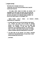
6.2 Replacement of filter element Service life of filter element varies because of different service conditions, generally, replace once a year.
6.1Fault phenomenon, cause and solution Fault phenomenon
6SXZ series Grains cereals color sorter
Disconnection occurred to the valve core
Replace the ejector
Color sort board has been damaged
Replace color sort board
Dust inside the ejector
Cyclic high frequency test of the ejector
Low air pressure
Check pressure gauge and relevant air circuit
Big difference in temperature between the material and the material chute
Adjust temperature of the chute to approximate that of the material.
Dust agglomeration
Clean the chute with soft cloth
Chute with scratch
Sand papering or replace it
MAIN FILTER IN
OUT
FILTER ELEMENT
SHELL WATCHING WINDOW
Correctly select sort mode Frequent operation for solenoid Wrong ejector valve Position of background plate not properly set Readjust background plate No color separation
Low sensitivity
Readjust sensitivity
haven't been power on
Power on the solenoid valve power supply
Dust on the sorting glass
Remove dust manually or by soft cloth
Incomplete for the color sorter
Check or replace rubber strip
Incomplete or poor ash removing for the rodless cylinder
Adjust ash wiper and the ash wiping speed
High sensitivity
Readjust the sensitivity
Improper adjustment of background plate
Readjust the background plate
Figure 6-1 Filter diagram Poor Color Separation Effect
Poor Separation Effect of Complete Machine Side
6.2.1 Replacement of components of cooling fan's filter netting Clean filter netting components once a month and immediate cleaning is also required when it is dirty.
Raw material with high quantity of impurity Reduce the yield
Color sorter stops working frequently
30
Color sorter is under pressure
Check pressure; readjust if the gas circuit is too far away from the sorter
Frequent pressure protection
Clean and open the pipeline by cleaning or replacing the filter element
Motor three-phase winding is damaged
Replace the motor
A.C. contactor damaged or poor contact
Maintain or replace A.C. Contactor
Thermorelay damaged or poor contact
Maintain or replace thermorelay
380v power supply phase shortage
Maintain charging line
Three-phase voltage imbalance
Adjust transformer to achieve three-phase voltage balance
Control switch circuit damaged or with problem
Check the control switch and circuit
Figure 6-2 filter netting components of cooling fan
31
6SXZ series Grains cereals color sorter
6SXZ series Grains cereals color sorter
Chapter VII Electrical Wiring Diagram
6.3 Notes in winter Preheat 30 minutes before startup, with working environment temperature above+5℃ , particularly in northern areas.
7.1 Parts layout
(1)As it is cold in winter, each valve should be opened slowly to prevent high speed air flow which may cause pipe freezing. (2)After each shift, it is required, strictly in accordance with requirement, to discharge residue gas and water inside equipments, preventing freezing. (3)Judge if any blocking in the air feed pipes as follows: When the color sorter is under operation and restarts the air compressor, to check if the value showed by the manifold pressure gauge on the side of the sorter is the same as that of the air compressor. If it is lower than the value of the air compressor pressure gauge, it means the pipe is blocked (filth blockage or ice clogging), please clean the pipe and each filter element.
6.4 Notes about in areas with high humidity (1)In southern areas where humidity is high, it is recommended for customer to install double water filters. ( 2) User should discharge water once two hours based on the field situation as the moisture entering machine may reduce its service life. ( 3) Check drainage in each filter (including inside part) in the gas circuit, and periodically replace the filter element. (4)Ensure the normal operation of machine by careful maintenance, thus prolonging its service life. Warning: please power off by the switch key and then set the air switch on the side of the mechanical frame at OFF before cleaning or replacing it. Note: Do not touch CCD camera lens as it will affect the color separation effectiveness if not correctly set and adjusted. Figure 7-1 Parts Layout
32
33
6SXZ series Grains cereals color sorter
7.2 Circuit diagram
34
35
6SXZ series Grains cereals color sorter
36
6SXZ series Grains cereals color sorter
37
6SXZ series Grains cereals color sorter
Chapter VIII List of Accessories, fittings and Wearing Parts 8.1 Accessory list Form 8-1 Accessory list N0.
Name
Specification
Unit
Quantity
1
Feeder assembly
/
PCS
1
2
Deash brush
Rubber brush
PCS
/
3
Allen wrench
1.5-6
PCS
1
4
Ball valve
1〞
PCS
1
5
Double head short screw
1〞
PCS
/
6
Access hopper
/
PCS
/
Specifications are based on product model
Remarks
For the filter import and export
8.2 List of customer-provided equipment and fittings Form 8-2 List of customer-provided equipment and fittings Name
Specification
Unit
Quantity
Remarks
1
Air compressor
/
PCS
1
Depends on product model
2
Air tank
/
PCS
1
Depends on product model
3
Air tank fitting
/
PCS
1
Depends on product model
4
Quality certificate forpressure vessel
/
PCS
1
Should meet the product specifications
Remarks
N0.
8.3 List of major parts Form 8-3 List of major parts N0.
Name
Specification
Unit
Quantity
1
Display
/
PCS
1
2
CCD camera
/
PCS
/
Quantity is related to the model
3
Camera lens
/
PCS
/
Quantity is related to the model
4
Control board
/
PCS
1
5
Sorting plate
/
PCS
/
Quantity is related to the model
38
6SXZ series Grains cereals color sorter
Chapter IX Warranty Card
8.4 List of wearing parts Form 8-4 List of major wearing parts
9.1 Three-Guarantees instruction Replacement method
N0.
Name
Specification
Average service life
Identification method
1
Deash brush
Rubber brush
Depends on field condition
Failure to remove Replace ash removing brush dust on glass surface
/
1000 hours or one year
Take out the outer cover, rotate filter element, remove and replace it.
2
Filter element
6SXZ series Grains cereals color sorter
* Note: The above parts and specifications for reference only, the actual use of the prevail.
Thanks for choosing PRECISION color sorter, in order to achieve the desired effects as well as enjoy rights, you are recommended to read the following contents before using the color sorter: (1)Read Instruction Manual carefully. (2)It is forbidden to make arbitrary changes to color sorter and its accessories, or else bear the consequences. (3)“Warranty” services are provided for the product, with its items and validity period detailed in the service specification. (4)For those exceeding “Warranty” service periods, our company will, with the high responsible attitude, provide paid service. (5)The warranty card with each for a set of machine is released with the Instruction Manual, please keeps it carefully, no replacement for the loss of it.
9.2 Warranty Service Rules The warranty service validity period include the complete machine validity period, major parts quality warranty period, wearing parts and other parts warranty period.
9.2.1 One year validity period of warranty for complete machine Validity period for complete machine: calculated from the dated of issuing purchasing invoice. Those who lost warranty card but able to prove the purchased product within warranty validity period can apply to sellers for warranty card which will be supplemented within 10 days after application. The renewed warranty period will be recalculated if replacing goods, with replacing seal on the invoice by the seller. (1)Free warranty for goods with flaw out of manufacturing. (2)Replace goods that cannot be repaired because of manufacturing quality. (3)Replace goods that cannot be used because of manufacturing quality. (4)If safety performance faults or usability faults occurred within 15 days from the date of purchase, company will replace or repair goods according to users' requirements. (5)Products having failure in product quality within warranty period can be repaired in 30days from the date of sending for repair, and guaranteed for its normal use. Damage caused to the product by repair will be compensated by our company. If products are not well repaired in 30days from the date of sending for repair, the fact should be recorded in the maintenance record and the product will be replaced with one of same model and specification. Our company will be freed of any warranty liability: (1)User fails to prove that the product's within warranty period. (2)Product's warranty period is invalid.
9.2.2 Main parts quality assurance period of 2 years Calculation of the main parts of the quality assurance period: from the date of purchase began to calculate (subject to invoice), but to deduct the "three packs" within the repair period (including to be repaired) occupied by the time; in the "three packs" within the validity of the main components of the failure, after the replacement of the main components of the "three packs" valid, since the replacement from the date of recalculation. The following circumstances do not bear the responsibility of the three parts involved:
39
40
6SXZ series Grains cereals color sorter
( 1) due to failure to use the instructions in accordance with the instructions, maintenance, resulting in damage; (2) the use of instructions that may not be installed, disassembly, and self-modification, demolition to change the machine performance or cause damage; (3)failure, the agricultural users to improperly handle their own causes of failure can not make technical appraisal; (4)due to non-product quality causes other man-made damage;
9.2.3 Three months validity period of warranty for wearing parts and other parts Validity period of warranty for wearing parts and other parts: calculated from the dated of purchase (subject to the invoice),and period for repair within warranty period (including waiting for repairing) will be deducted; if any malfunction occurred to wearing parts and other parts within the warranty period, the warranty period for those renewed parts will be recalculated from the date of replacement. Our company will not bear any warranty liability for following circumstances: (1) Damage caused by misoperation and improper maintenance out of not to be in accordance with the instruction manual; (2) Damage or changes in mechanical performance caused by arbitrary modification and dismantle which is specifically forbidden in the instruction manual;
9.2.4 Three Guarantees Document Review Record Form
41
Individual Conclusion Product No.
Brand name
Model
Product No.
Production unit
power
3
Manufacturer
4
Repairer
5
Production Date
Name of User
Address of User
Name of Product Product Model
Product Serial No.
Comments of Warranty Service Personnel Comments of Sales Person Comments of Service Department Approval by Supervisor Date of Return and Exchange
User signature
9.4 Warranty Card Form 9-2 Warranty Card
Product Model
Product Serial No.
Manufacturer
Hefei Taihe Optoelectronic Technology Co., Ltd.
Seller
Hefei Taihe Optoelectronic Technology Co., Ltd. (Seal)
product
Supporting 2
Model
Form9-1Return and Exchange
Name of Product
Review the project and the results Brand name
1
9.3 Return and Exchange
Reason for Return and Exchange
(5)Damage caused by force majeure
N0.
6SXZ series Grains cereals color sorter
Name
Address
Phone
Postal
Name
Address
Phone
Postal
Purchasing Date
Invoice Number
Name of User
Phone
Detailed Address of User
Sales records (including sales, sales location, sales date, purchase invoice number and other items)
42
6SXZ series Grains cereals color sorter
9.5 Maintenance Record Sheet Form 9-3 The first copy of the maintenance record sheet Date of sending for repair
Date of repairing
Failure cause: Result of treatment: Signature of repairman Address of manufacturing enterprise After-sales service phone
Signature of user
Intersection of Yulan Avenue and Fangxing Avenue, Taohua Industrial Park Development Area, Hefei Economic and Technological Development Zone, Anhui, China +86 551 68588368
Post Code
First user retention (triple)
Problems reflected by user
230601
--------------------------------------------------------------------------Form 9-4 The second copy of the maintenance record sheet Date of repairing
Problems reflected by user Failure cause: Result of treatment: Signature of repairman Address of manufacturing enterprise After-sales service phone
Signature of user
Intersection of Yulan Avenue and Fangxing Avenue, Taohua Industrial Park Development Area, Hefei Economic and Technological Development Zone, Anhui, China +86 551 68588368
Post Code
230601
The second sale after the retention (triple)
Date of sending for repair
--------------------------------------------------------------------------Form 9-5 The third copy of the maintenance record sheet Date of repairing
Problems reflected by user Failure cause: Result of treatment: Signature of repairman Address of manufacturing enterprise After-sales service phone
Signature of user
Intersection of Yulan Avenue and Fangxing Avenue, Taohua Industrial Park Development Area, Hefei Economic and Technological Development Zone, Anhui, China +86 551 68588368
Post Code
230601
Third Union sellers retained (triple))
Date of sending for repair
44