![Technical Drawing [PDF]](https://pdfs.asia/img/200x200/technical-drawing.jpg)
14 0 135 MB
NDAMENTALS CAD DESKS Second Edition
/^
Goetsch Nelson Chalk
Digitized by the Internet Archive in
2011
http://www.archive.org/details/technicaldrawingOOgoet
TECHNICAL DRAWING FUNDAMENTALS
•
CAD
•
DESIGN
TECHNICAL DRAWING FUNDAMENTALS
•
CAD
•
DESIGN
Second Edition Goetsch John A. Nelson William S. Chalk David
m I? Y
(R)
Delmar Publishers
Inc.
L.
9
NOTICE TO THE READER Publisher does not warrant or guarantee any of the products described herein or perform any independent analysis in connection with any of the product information contained herein Publisher does not assume, and expressly disclaims, any obligation to obtain and include information other than that provided to it by the manufacturer. is expressly warned to consider and adopt all safety precautions that might be indicated by the described herein and to avoid all potential hazards By following the instructions contained herein. the reader willingly assumes all risks in connection with such instructions
The reader activities
The publisher makes no representations
or warranties of any kind, including but not limited to. the warranties purpose or merchantability, nor are any such representations implied with respect to the material set forth herein, and the publisher takes no responsibility with respect to such material. The publisher shall not be liable for any special, consequential or exemplary damages resulting, in whole or in part, from the readers' use of. or reliance upon, this material. of fitness for particular
DEDICATION From David
L.
Goetsch To Savannah Day, Toby, Dustin, and Clifford Jay
From John
Nelson
A.
my
To
Delmar
wife, Joyce
CAD
staff
Associate editor: loan
Graphics developed by Engineering Graphics Technology State University Technical Branch. Okmulgee. OK. Member of Consortium for Manufacturing Competitiveness.
Oklahoma
Gill
Editing manager: Gerry East
Publications coordinator: Karen Seebald Design coordinator: Susan Mathews For information, address Delmar Publishers
Ball-bearing model based on a drawing by Leonardo da Vinci. Photo: Brian Merrett. Collection of The Montreal Museum of Fine Arts.
Inc.
Detail from
PO
Box 15015 Albany, New York 12212-5015 3 Columbia Circle,
Copyright All rights
of this
I989 by Delmar Publishers
C
Leonardo da
Vinci
Madrid
Biblioteca Nacional. Madrid.
Inc.
reserved. Certain portions of this work C 1986.
work may be reproduced or used
in
No
part
any form, or by any
means-graphic, electronic, or mechanical, including photocopying, recording, taping, or information storage and retrieval systemswithout written permission of the publisher.
Printed in the United States of
America
Published simultaneously in Canada
by Nelson Canada,
A division of The Thomson Corporation 10
9
8
6
7
5
Library of Congress Cataloging in Publication Data
Goetsch, David
L.
Technical drawing: fundamentals. CAD. design David
)ohn A. Nelson. William cm. p. Rev. ed. of: Technical
S.
Chalk— 2nd
L.
Goetsch.
ed.
drawing and design, t
1
986.
Includes index.
ISBN 0-8273-3280-7 I. Mechanical drawing. William.
III.
I.
Goetsch. David
Nelson. |ohn L.
A.,
1935-
II.
Chalk
Technical drawing and design.
IV Title.
T353.G63
I989
604.2'4-dc
1
88-34462 CIP
MS
I.
f.20v.
courtesy of
Brief Contents
PREFACE
x
SECTION ONE Introduction ing,
2
BASICS
•
and Line Techniques 67
SECTION TWO
and Their Use 22 2 Geometric Construction 93
Drafting Instruments
I
3
Lettering, Sketch-
TECHNICAL DRAWING FUNDAMENTALS
•
145
4 Multiview Drawings 146 5 Sectional Views 193 6 Auxiliary Views 225 8 Patterns and Developments 289 9 Dimen7 Descriptive Geometry 24 5 sioning and Notation 323
SECTION THREE
•
COMPUTER-AIDED DRAFTING
10 Computer-Aided Drafting Technology 392
11
391
Computer-Aided Drafting
Operations 407
SECTION FOUR
•
DESIGN DRAFTING APPLICATIONS
429
Geometric Dimensioning and Tolerancing 430 13 Fasteners 457 15 Cams 521 16 Gears 535 17 Assembly and Detail Drawings 552 18 Pictorial Drawings 579 12
14 Springs 505
SECTION FIVE
•
19 Welding 620 tronic Drafting 705
RELATED TECHNOLOGY
619
20 Shop Processes 644 21 Pipe Drafting 684 22 Elec23 Charts and Graphs 720 24 The Design Process 791
APPENDIX A MECHANICAL DRAFTING MATHEMATICS APPENDIX B TABLES
GLOSSARY INDEX
935
928
874
842
Contents
SECTION ONE Introduction
BASICS
•
1
2
drawings described types of drawings types of technical drawings purpose of technical drawings applications of technical drawings regulation of technical drawings what students of technical drawing and drafting should learn review •
•
•
•
•
•
•
Chapter
•
1
Drafting instruments and their use
conventional and ing sets
CAD/CAM
scales
•
butterfly-type scriber writer
•
•
equipment
drafting
measuring
•
ink tools
•
airbrush
care of drafting equipment
Chapter
2
freehand lettering sketches
•
Chapter
3
and
Lettering, sketching,
•
•
sizes
review
•
whiteprinter
•
draw-
files
•
•
•
open-end type-
problems
•
line
techniques
67
•
•
•
Geometric construction
•
mechanical lettering sets
•
freehand lettering techniques line work sketching techniques review
sketching materials
•
conventional drafting requisites
•
technical pens
•
paper
•
22
sketching
•
•
•
types of
problems
93
geometric nomenclature elemental construction principles polygon construction review problems circular construction supplementary construction •
•
•
SECTION TWO Chapter 4
TECHNICAL DRAWING FUNDAMENTALS
•
Multiview drawings
•
•
145
146
centering the sketching procedure orthographic projection planning the drawing curve plotdrawing rounds and fillets runouts treatment of intersecting surfaces how to represent aligned features cylindrical intersections incomplete views ting problems review first-angle projection holes conventional breaks visualization •
•
•
•
•
5
•
•
and keyways tion
•
•
review
Chapter 6
•
•
•
Auxiliary views
•
•
length of a line
VI
line
and
•
holes, ribs
•
multisection
and webs, spokes
intersections in sec-
shafts in section
225
•
•
how
and
how
partial views
•
auxiliary section
•
•
Descriptive geometry
other views
between a
fasteners
secondary auxiliary views problems
review
descriptive geometry projection line into
•
section lining
•
webs
problems
half auxiliary views
7
direction of sight
•
sections through ribs or
aligned sections
•
auxiliary views defined
Chapter
•
•
193
cutting-plane line
kinds of sections
•
•
Sectional views
sectional views
•
•
•
Chapter
views
•
•
•
•
•
•
245
steps used
•
to locate a point in
notations
space
to construct a point view of a line
a point in
space
•
how
•
fold lines
(right view) •
how
•
•
how
how
to project a
to find the true
to find the true distance
to find the true distance
between two
parallel
how to find the true distance between two non-parallel lines how to project a how to construct an edge view of a plane surface how to find plane into another view how to find the true the true distance between a plane surface and a point in space how to determine the visibility of lines how to determine angle between two planes how to determine the piercing point by construction the piercing point by inspection how to find the intersection of how to determine the piercing point by line projection how to find the intersection of a cylinder and a plane two planes by line projection how to find the intersection of a sphere and a plane surface surface by line projection how to find the intersection of two prisms bearings, slope, and grade how to conhow to construct a line struct a line with a specified bearing, slope angle, and length problems review with a specified bearing, percent of grade, and length lines
•
•
•
•
•
•
•
•
•
•
•
•
•
•
•
•
•
Chapter 8
Patterns and developments
•
289
parallel line development developments notches true-length diagram development •
•
•
•
Chapter 9
triangulation development problems
radial line
bends
•
Dimensioning and notation
•
•
•
review
•
•
323
laying out dimensions steps in dimension components dimensioning systems summary of dimensioning rules specific dimensioning techniques dimensioning problems review rules for applying notes on drawings notation •
•
•
•
SECTION THREE Chapter
•
•
•
•
10
COMPUTER-AIDED DRAFTING
•
Computer-aided drafting technology
•
CAD
overview of
•
computer-aided drafting systems
•
•
391
392
CAD hardware
CAD
•
software
modern CAD system configurations advantages of CAD microCADD microCADD in the beginning advantages of microCADD limitations of microCADD
CAD
users
•
•
•
•
•
•
•
•
review
Chapter
1
Computer-aided drafting operations
•
1
general system operation
mands
review
•
12
commands
manipulation
•
commands
DESIGN DRAFTING APPLICATIONS
•
Geometric dimensioning and tolerancing
•
output com-
•
problems
SECTION FOUR Chapter
input
•
407
429
430
summary of geometric dimensioning and
general tolerancing positional tolerancing terms geometric dimensioning and positional tolerancing defined modifiers feature control symbol true position cylindricity flatness straightness circularity (roundness! angularity parallelism perpendicularity profile runout review problems •
•
•
•
•
•
Chapter
13
pitch
•
•
•
•
•
•
•
457
Fasteners
•
•
•
•
classifications of fasteners
inch (TPI)
•
•
threads
screw thread forms
•
and multiple threads
single
thread representation thread relief (undercut) and keyseats grooved fasteners spring pins review problems •
•
•
tap and die
screw, bolt,
•
•
•
•
threads per
right-hand and left-hand threads
•
and stud
fastening systems
•
•
rivets
•
•
keys
retaining rings
•
•
Chapter
14
•
Springs
spring classification spring data
•
how
to
spring design layout
views
•
review
•
•
505
helical springs
•
flat
springs
draw a compression spring •
•
terminology of springs required draw an extension spring other section view of a spring isometric
standard drafting practices
•
•
how
to
•
•
problems
VII
Chapter
cam •
15
basic types of followers cam mechanism cam terms cam motion cam from the displacement diagram how to draw a cam with an offset how to draw a cam with a flat-faced follower timing diagram dimensioning
principle
cam
•
•
•
•
•
16
535
gearratio
•
diametral pitch
Chapter
gear train
•
17
pitch diameter
•
pressure angle
•
to use a gear tooth caliper
gear
required tooth-cutting data
•
the engineering department
gear blank
•
backlash
•
detail drawings
•
•
•
design and layout of
•
basic terminology
•
measurements required rack bevel gear worm and gears review problems
center-to-center distances
•
materials
•
Assembly and
•
•
problems
•
Gears
:
kinds of gears
worm
•
•
review
•
Chapter
•
521
laying out the
follower a
Cams
•
•
•
•
552
drawing revisions invention agreement title block size checking procedure numbering system parts list personal technical file the design procedure working drawings patent drawings computer drawings (see Chapters 10 and 11) review problems •
•
of lettering within title block
•
•
Pictorial drawings
•
•
•
•
•
18
•
•
•
•
Chapter
•
•
579
axonometric drawings oblique drawings types of pictorial drawings perspective drawing isometric principles nonisometric lines hidden lines offset measurements center lines box construction irregularly shaped objects isometric curves iso•
•
•
•
•
•
•
•
•
•
•
•
metric circles or arcs isometric arcs isometric knurls isometric screw threads isometric spheres isometric intersections isometric rounds and fillets isometric di•
•
•
mensioning
SECTION FIVE Chapter
19
•
isometric templates
•
RELATED TECHNOLOGY
•
Welding
•
•
perspective drawing procedures
•
review
•
problems
•
619
620
welding processes length of weld placement basic welding symbol size of weld of weld intermittent welds field welds weldprocess reference contour symbol seam projection weld ing joints multiple reference line spot weld types of welds weld welding template review problems •
•
•
•
casting
holding devices
2
1
•
•
forging
Chapter 22
•
diagrams
Chapter 23
•
•
review
•
•
•
fittings
•
types of valves
•
pipe drawings
dimen-
705
connection diagrams schematic diagrams problems review printed circuit board drawings •
•
Charts and graphs
•
block diagrams
•
•
720 components
five
basic
The design process
791
•
•
•
specific charts
and graphs
•
problems
Chapter 24
•
the design process: phases and steps problems review
learning the design process
projects: routine
vin
•
problems
•
functional classes: an overview •
•
Electronic drafting
electronics symbols
•
•
•
•
684
types of joints and
•
sioning pipe drawings
time
extruding
•
heat treatment of steels
Pipe drafting
•
types of pipe
review
644
•
Chapter
logic
•
special workstamping machining automation and integration (CAM and CIM review CIM FMS industrial robots computer-aided manufacturing (CAM)
shop processes •
•
•
•
Shop processes
•
•
•
•
Chapter 20
•
•
•
•
FMSl
•
•
and non-routine
•
•
•
•
design
Appendix A
•
Mechanical drafting mathematics
842
rounding decimal fractions expressing common fractions as mathematics for drafters evaluating formulas millimeter-inch equivalents (conversion factors) decimal fractions arithmetic operations on angles expressed in degrees, minutes, ratio and proportion degrees, minutes, seconds— decimal degree conversion types of angles and seconds types of triangles common polygons definitions of angles formed by a transversal geometric principles of circle circumference, central angles, arcs, properties of circles geometric princigeometric principles of angles formed inside a circle and tangents internally and ples of angles formed on a circle and angles formed outside a circle trigonometry: trigonometric functions trigonometry: basic externally tangent circles trigonometry: common drafting applications trigonometry: oblique calculations of sides review triangles— law of sines and law of cosines •
•
•
•
•
•
•
•
•
•
•
•
•
•
•
•
•
•
•
•
•
Appendix B Glossary Index
•
contents
874
928
935
i\
Preface is intended for use in such courses as basic and advanced technical drawing, basic and advanced drafting, engineering graphics, descriptive geometry, mechanical drafting, machine drafting, tool and die design and drafting, and manufacturing drafting. It is appropriate for those courses offered in comprehensive high schools, area vocational
Purposes Technical Drawing
schools, technical schools,
community
and technical schools, and
at the
omore
New
Features in the 2nd Edition
Four new chapters, including Pipe tronic Drafting
and
Drafting, Elec-
Charts and Graphs.
Brand new design chapter introduces students to the unique "design process" they will need to succeed in industry.
colleges, trade
freshman and soph-
Completely new chapters and
levels in universities.
tolerancing
and
in geometric dimensioning
dimensioning and notation
have
been commented upon as "the best presentation of dimensioning information in any currently available text." Prerequisites
There are no prerequisites. The text be-
gins at the
Over 400 new drawing problems, most of which
to the
are classified
most basic level and moves step-by-step advanced levels. It is as well suited for students who have had no previous experience with
technical drawing as
it
is
for
students with a great
deal of prior experience.
range, have
the "challenging to very difficult" tested.
Rewritten, in-depth Descriptive Geometry chapter will give students a solid foundation in this subject.
CAD Innovations An advantage of the text is that it has evolved during a time when the world of technical drawing and design is undergoing a period of major transition from manual to automated techniques. Computer-aided drafting (CAD) is slowly but steadily gaining a foothold. This transitional period will last
at least until the turn of the century, with
in
been classroom
CAD gaining
fully updated to reflect the microCAD technology and are based on AutoCAD. VersaCAD*. and CADKEY" systems.
chapters are
very latest
in
Much new
art
is
CAD-generated to familiarize
your students with the style of machine-drawn
Computer Integrated Manufacturing (CIM) mation
is
fully
art.
infor-
integrated into the Shop Processes
chapter,
greater acceptance every year.
This transition has created a need for a major text that deals with both traditional knowledge and skills
and CAD-related knowledge and skills. Technical Drawing fills this need. Even when the world of technical drawing and design has become fully automated, drafters and designers will still need to know the traditional basics and technical drawing fundamentals. These basic factors will not change. Therefore, the traditional fundamentals are treated in depth in
done on existing art and problems to set a high standard for the 2nd Edition.
Technical screening
Tested and Proven Features Step-by-step explanations of drawing procedures
and techniques. Written
in
language your students
will
understand:
technical terms are defined as they are used.
this text.
What is changing, and will continue to change, is way that drafters and designers prepare techni-
the
For this reason, CAD is also treated in of the drawings and illustrations were prepared on various CAD systems. Along with this treatment, Technical Drawing offers students and teachers a special blend of the manual and autocal drawings.
depth, and
many
mated knowledge and techniques that are needed now through the turn of the century, and even beyond. Another advantage of the text is that it was written after the latest update of the most frequently used drafting standard— ANSI Y14.5. This standard was updated with major revisions in 1982, and is now ANSI Y14.5M— 1982. Consequently all dimensioning and tolerancing material in Technical Drawing is based on this most recent edition of the standard. Preface
Unique blue and red color format depicts
iso-
more clearly than "flat" black-andwhite drawings: shaded effect is an excellent metric views
"depth" projector. Text
and
illustrations are located in
direct rela-
tionship to each other.
CAD
techniques are integrated thoughout the two fully dedicated chapters.
text as well as in
"Real-world" techniques and drawings are highlighted throughout the text.
Although the emphasis is on mechanical drafting, other pertinent drafting subjects are included for a comprehensive, well-rounded approach to technical drawing.
The Package Comprehensive
About the Authors
Textbook.
Comprehensive, up-to-date manual Workbook.
new multi-function Workbook with drawing problems that can be done manually or with CAD. via AutoCAD*, VersaCAD*, CADKEY*, or MicroStation*. All
Instructor's
ters
Guide with overhead transparency mas-
and complete course
syllabus.
Manual with solutions for selected problems from both the textbook and the manual workbook.
Solutions
Acknowledgments
edge the
The authors would
efforts of
Goetsch is Dean of Technical Education of Computer-Aided Design and Drafting at Okaloosa-Walton Community College in Niceville, Florida. His drafting and design program has David
like to
acknowl-
many people without whose
assis-
L.
and Professor
won
national acclaim for its pioneering efforts in the area of computer-aided drafting (CAD). In 1984, his
school was selected as one of only ten schools in the country to earn the distinguished Secretary's Award for an outstanding Vocational Program. Goetsch is a widely acclaimed teacher, author, and lecturer on the subject of drafting and design. He won Outstanding Teacher of the Year honors in 1976, 1981. 1982. 1983, and 1984. In 1986 he won the Florida Vocational Association's "Rex Gaugh Award" for outstanding contributions to technical education in Florida. He en-
tance this project would not have been completed. is made to Edward G. Hoffman, author of Chapter 20, "Shop Processes"; and Robert D. Smith, author of Appendix A, "Mechanical Drafting Mathematics." We thank Ray Adams, Dana Welch, Susan Wilkinson, and Ron Ryals for their assistance with illustrations. We thank Deborah M. Goetsch for her assistance with photography and typing. We thank Joyce Nelson for her assistance
Special acknowledgment
with typing.
The following individuals reviewed the manuscript and made valuable suggestions to the authors. We and the publisher greatly appreciate their contributions to this textbook.
Ed Allard Allen Park, Michigan Mr.
Canada
r
c
Mr. John English
Kentucky State
Mr. Larry Ralston
University
St.
Frankfort, Kentucky
St.
James
Joliet
Fox Junior College
Goetsch
L.
Ryerson Technical Institute Toronto,
Mr.
David
Mr. Ted Jansen
Louis Technical Ann, Missouri
Mr. Robert
Rhea
A.
University of Texas
Houston, Texas
United States Department of Education
Joliet, Illinois
===== Secretary
Mr. Mr. Gerry Hansen Santa Cruz. California
's
Aicard
=====
Hugh F Rogers
Pennsylvania State University
State College. Mr. Don Hartsharn Columbus State Community College
Mr.
Columbus, Ohio
Chicago,
The Secretary of Education recognizes Okaloosa- Walton Junior College for an outstanding Vocational Education Program in 1984, Drafting and Design Technology
Pennsylvania
P^7?*zg&&SL T H BeD
Gary Rybicki
I'niicd
Sutrn ScvrrUrv of Education
Illinois
Elizabeth Smith
Northern Virginia Community College Alexandria, Virginia
.0:1
..8
.0-£
"
W
o-?
9-C
*J
VT
lima
1-
ino«9
z/i
i
Introduction
13
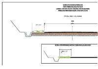
Technical drawings are equally important to engiand various other individuals work-
signs. Technical
neers, designers,
of individuals
mon
ing in the manufacturing industry. Manufacturing engi-
neers use technical drawings to
document
drawings guide the collective efforts are concerned with the same com-
who
goal, Figures 1-30
and
1-3
1.
their de-
NOTE
CX-040000
PNEUMATIC TRANSMITTER SHOWN. PIPING SAME FOR ELECTRONIC TRANSMITTER, EXCEPT AIR SUPPLY AND OUTPUT CONNECTIONS ARE NOT REQUIRED. TRANSMITTER MOUNTED AIR SUPPLY BELOW PROCESS LINE. SEE DETAIL CX-0100A0
SEE DETAIL NO, CX-040000 TO RECEIVER*
,^4^ AIR SUPPLY SEE DETAIL NO CX-0100A0
RUN TO WITHIN G" OF FLOOR
RUN TO WITHIN 6" OF FLOOR
DETAIL "A" D/P CELL WITH MANIFOLD USING 1/2* TUBING
D/P CELL W/0 MANIFOLD USING 1/2" PIPE
SEE DETAIL NO, CX-040000
ITEM
DESCRIPTION
3-VALVE MANIFOLD 1/2* VALVE 1/4* VALVE
SPEC
ITEM
DESCRIPTION
SPEC
1/2"T. TEE 1/2-T. X 1/4-P. TEE
1/2T. X 1/2*P. ELBOW 1/2" TEE 1/4" PIPE 11 1/2* X 1/4* TEE 1/2" TUBING 12 1/2* PIPE 1/2" UNION 19 1/2" 90' ELBOW 1/2"T. X 1/2-P. COW. 17 ZNrnwvNTRrzcN xNrmiimoN ormn. THE RUST D/P CELL TRANSMITTERS ENGINEERING COTPflNY FOR LIQUID AND STEAM SERVICE
ITEM
DESCRIPTION
20
1/4" UNION 1/2" NIPPLE
21
SPEC
10
mritiat
n"*
CF-040001 BR 1983
Figure 1-30 Isometric mechanical drawing
14
Section
{Courtesy The Rust Engineering
Company)
BILL OF MATERIAL NO UNIT DESCRIPTION VALVE. VALVE. VALVE. VRLVE. VRLVE. VRLVE.
BALL. 8" ISO- ANSI RF FULL PORT. C S. BOLL. 4" 600* ANSI RF. C S. PLUG. 2 - 2000« UP. TmRD CHECK. • 600« ANSI RF. CS PLUG. 1" 2000* UP. ThRD RELIEF, rxr PULSATION OAHPNER (FLUIO KENE TICSHDISCH) PULSATION OAHPNER (SUCTION) FLANGE. 4" 600» ANSI RFUN U/BOL TS4GASKET FLANGE. 8" ISO* ANSI RFUN U/BOL TS&GASKE T FLANGE. 4" 1S0« RNSI RFUN U/BOL TS1GRSKET FLANGE. 2 1/2" 600«ANS1 RFUN U/BOL TS4GASKE T REDUCER. CONC. 8 - X4-. BFu. SCM 40 REDUCER. CONC. 3"X2 1/2". BFU. SCM 40 REOUCER. CONC. 4-X3-. BFU. SCh 40 UNION, r 2000* UP. FS. O-RING UNION. 2" 2000' UP. FS. O-RING SUAGE. 2 - X\ m FS. X-HVT. NPT .
ELBOU. TEE.
ELBOU. ELBOU.
2000- UP. 90". NPT 2000« UP. NPT
2"
2"
48'
90* 90'
LONG RADIUS BFU. SCH 40 LONG RADIUS BFU. SCM 40
TEE. I2-X12-X8". BFu. SCH 40 TEE. 6-X6-X4-. BFU. SCH 40 THREAO-O-LET 1" ON 4". 6000* FS TEE. 4-X4-X2 - BFU. SCH 40 PLUG. 1/2" 2000* HEX HEAD. FS. NPT FLANGE. BLIND. 4" 600« ANSI RF .
FLANGE. BLIND. 8" 150« ANSI RF PIPING. 8" SCH 40. A-I06 GR B PIPING. 4" SCH 40. R-106 GR B PIPING. 2" SCH 80. A-106 GR B PIPING. I" SCH 80. A-106 GR B NIPPLE. 2-X3" SCH 80. A-106 GR B. NPT NIPPLE. 1-X2" SCH 80. A-106 GR B. NPT THREPO-O-LET 1/2" ON 4". 6000* FS THREAO-O-LET 1/2" ON 8". 6000" FS PLUG. 1/2" 2000« HEX HEAO. FS. NPT THREAO-O-LET 2" ON 12". 6000« FS FLANGE. 3" 600- ANSI RFUN U/BOL TS4GASKET
ENGINEERING GZHPHICS,
I
INC. I
^£S£SJS
w»«!w?
PERIPHERAL WATER INJECTION DESCRIPTION:
FUTURE PUMP
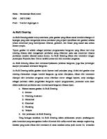
Figure 1-31 Isometric piping schematic {Engineering
Regulation of Technical Drawings Technical drawing practices must be regulated because of the diversity of their applications. Just as the English language must have certain standard rules of grammar, the graphic language must have certain rules of practice. This is the only way to ensure that all people attempting to communicate using the graphic language are speaking the same language.
Standards of Practice A number of different agencies have developed standards of practice for technical drawing. The most widely used standards of practice for technical drawing and drafting are those of the U.S. Department of Defense DOD), the U.S. Military (MIL), and the American National Standards Institute (ANSI). The American National Standards Institute does not limit its activities to the standardization of technical drawing and drafting practices. In fact, this is just one of the many fields for which ANSI maintains a continuously updated set of standards. Standards of interest to drafters, designers, checkers, engineers, and architects are contained in the "Y" series of ANSI standards. Figure 1-32 contains a list of ANSI standards frequently used in technical drawing and drafting specifications. (
Graphics.
«3
PIPING
EG126
\nc.
What Students and
of Technical Drawing Drafting Should Learn
Many people in the world of work use technical drawings in various forms. Engineers, designers, checkers, drafters, and a long list of related occupations use technical drawings as an integral part of their jobs. Some of these people must be able to actually
make
be able be able
to read to
do
drawings; others are only required to
and interpret drawings; some must
both.
SIZE
AND FORMAT.
LINE
CONVENTIONS AND LETTERING— YI4 2
.YI4
I
PROJECTIONS
YI4.3
PICTORIAL DRAWING
YI4.4
DIMENSIONING AND TOLERANCING
YI4.5M
SCREW THREADS GEARS, SPLINES AND SERRATIONS
YI46
GEAR DRAWING STANDARDS
YI4.7.I
MECHANICAL ASSEMBLIES
YI4I4
Figure 1-32 Sample
list
YI47
of drafting standards
Introduction
15
The learning required of technical drawing students can be divided into three categories: fundamental knowledge and skills, related knowledge, and advanced knowledge and skills. In the "fundamentals" category, students of technical drawing and drafting should develop knowledge and skills in the areas of drafting equipment; such fundamental drafting techniques as line work, lettering, scale use, and sketching; geometric construction; mul-
LEARNING CHECKLIST FOR STUDENTS OF TECHNICAL DRAWING FUNDAMENTAL
RELATED
ADVANCED
KNOWLEDGE AND SKILLS
KNOWLEDGE
KNOWLEDGE AND SKILLS
DRAFTING EQUIPMENT FUNDAMENTAL DRAFTING
TECHNIQUES SKETCHING GEOMETRIC CONSTRUCTION MULT1VIEW DRAWING SECTION VIEWS GRAPHICAL DESCRIPTIVE
MATH WELDING SHOP PROCESSES MEDIA AND REPRODUCTION
DEVELOPMENT GEOMETRIC DIMENSIONING AND TOLERANCING THREADS AND FASTENERS
tiview drawing; sectional views; descriptive geometry; auxiliary views; general dimensioning;
SPRINGS
CAMS GEARS MACHINE DESIGN DRAWING
GEOMETRY
PICTORIAL DRAFTING
DRAFTING SHORT-CUTS CAD TECHNOLOGY CAD OPERATION
AUXILIARY VIEWS
GENERAL DIMENSIONING NOTATION
Figure 1-33 Checklist for students of technical drawing
What students of technical drawing and drafting should learn depends on how they will use technical drawings in their jobs. Will they make them? Will they read and interpret them? This textbook is written for students
and
in
the fields of engineering, design, drafting,
architecture,
among
others,
who must be
able
and interpret technical drawings. These students should develop a wide range of knowledge and skills, Figure 1-33.
In the "advanced" category, students of technical drawing and drafting should develop knowledge and skills in the areas of development, geometric dimensioning and tolerancing, threads and fasteners, springs, cams, gears, machine design drawing, pictorial
16
Section
CAD
technology
{Courtesy
drafting, drafting shortcuts,
and CAD/CAM tech-
nology and operations. The latter area represents a significant
change
in
techniques used to create,
maintain, update, and store technical drawings. Fig-
ures 1-34 and 1-35. Figures 1-36 through 1-40 contain examples of sev-
to make, read,
Figure 1-34 Modern
and notation.
the "related knowledge" category, students of technical drawing and drafting should develop a broad knowledge base in the areas of related math, welding, shop processes, and media and reproduction. In
eral different kinds of technical
the "real world" of drafting.
CADKEYl
drawings taken from
Figure 1-35 Modern
CAD
system
(Courtesy Autodesk,
Inc.)
BILL Or *ATERIftl DESIGN lENGT
Cvc *fac-io» o
MS
3
a
« q
3
3
5
i
a
a
tp *> ft pit
3/e
'
•
m.t
«i» IT*
1 "lb 'W ;H14
H-ll
'
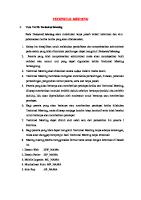
!-:dfird VARIABLE DRRUING FORHflT variable /me, symbol, text parameters clear, concise- presentation of
shop drawing information degree of accuracy offsets, -^xlentions, witness lines, d r awng size and location show 1, 2, 3, or 4 beams pe* sheet with or wthout 81" of Mater a s plot or, preprinted sheets o* b'ank paper down to 816" X 11" can enlarge any portion r or sict variable variable
clarifica
1
il-lU
Mi
l
drrhing fehtures AOQjr/O.VAL FEATURES parameters stored for automated shop and accounting system interface f vll communication capabilities b lr totally mteractive-NO INPU T SHEETS
FLEXIBILITY-USER ORIENTED SOFTU»RE for site specie a'ieral'OTs the po*e calculating and graphics capabilities m simple routines suited r or their unique situations pe-form tedious aspects of deto
user
can combine
cveri'ght
tio">
from ^
--nat'on
symbols can be user defined o r standard
GRAPHICS SrSTEn complete,
fully interactive g'aphic capab'iit'es for edii'ng and creating non-standa r d
CONNECTIONS double
angle
bolted, shear
tab,
end
plate, or weld to embedded plate DESIGNED BY RISC CODE (eigth edition)
coping, and edge distances calculated automatically definable plate, angle, or bolt sue for intentional over design
blocking,
Figure 1-36 Structural steel drawing
{Courtesy
full,
state-of-the-art gr a p-
complete suppct a"a l"a system configuration fully upgradable r freedom from obsolescence
SIGMR DESIGN
c
PROVEN OVERALL PRODUCTIVITY
=
6
TO
1
Sigma Design)
Introduction
17
o
1
of the 1/2 scale, Figure 1-55.
Figure 1-56 Architectural scale
(full size)
Architect's Scale
The
architect's scale
large buildings
and
is
used primarily
structures.
The
for
drawing
full-size scale is
drawing smaller objects. Because is generally used for all types of measurements. It is designed to measure in feet, inches, and fractions of an inch. Measure full feet to the right of 0; inches and fractions of an inch to the left of 0. The numbers crossed out in Figure 1-56 correspond to the 1/2 scale. They can be used, however, as 6 inches as each falls halfway between full-foot divisions. Measurements from are made in the opposite direction of the full scale, because the 1/2 scale is located at the opposite end of the used frequently
2'-9"
DISTAN CE
1/2" - 1'-0"S
ZE
for
of this, the architect's scale
Figure 1-57 Architectura
-2.50"
scale, Figure 1-57.
DISTANCE FULLSIZE
10
Civil
A
civil
engineer's scale
The number
X is
also called a decimal-inch
located
in the corner of the scale Figure 1-58, indicates that each graduation is equal to 1/10 of an inch or I". Measurements are read scale.
10.
2
1
Engineer's Scale Figure 1-58
Civil
engineer's scale
in
directly from the scale. The number 20, located in the corner of the scale shown in Figure 1-59, indicates that it is 1/20 of an inch.
Using the same scale for civil drafting, one inch equals two hundred feet, Figure 1-60, and one inch equals one hundred feet, Figure 1-61. A metric scale is used if the millimetre is the unit of linear measurement. It is read the same as the decimal-inch scale except that it is in millimetres, Figure 1-62.
250.0' DISTANCE 1" -200.0'
20 3
)4
Figure 1-59
24 Civil
4
5
^ engineer's scale (half scale)
Chapter
I
39
Pocket Steel Ruler
DISTANCE
2.50"
1/2 SIZE
The drafter should make use of a pocket steel ruler. The pocket steel ruler is the easiest of all measuring tools to use. The inch scale, Figure 1-63, is six inches long, and is graduated in lOths and lOOths of an inch on one side and 32nds and 64ths on the other side. The metric scale is 50 millimetres long (approximately six inches) and is graduated in millimetres and half millimetres on one side, Figure 1-64. Some-
lllllllllllllll
20 2
1
4
3
5
*4
1
Figure 1-60 Mechanical scale (half
size)
times metric pocket steel rulers are graduated 64ths of an inch on the other side.
DISTANCE
250.0'
1" = 100.0'
in
Measuring The metric system uses the metre (m) as its basic A metre is 3.28 feet long or about 3 3/8
dimension.
10
1
1
inches longer than a yardstick.
H Figure 1-61
scale
Civil
multiples, or parts,
Its
are expressed by adding prefixes. These prefixes represent equal steps of 1000 parts. The prefix for a thou-
sand 1000) (
is
the prefix for a thousandth (1/1000)
kilo-,
One thousand metres
(1000 m), therefore, equals one kilometre 1.0 km). One thousandth of a metre (1/1000 m) equals one millimetre (1.0 mm). Comparing metric to English then: is milli.
(
63.5
mm DISTANCE FULL SIZE One
mm) =
millimetre (1.0
0.001 metre (0.01 m)
=
.03937 inch
One thousand (1.0m)=
millimetres
(
1000
One thousand metres 1000 m)= km) = 328 1.0 feet 1
Figure 1-62 Metric scale
nun iwii
liiiiiui1THE
10THS
I
No.
100THS
LS.STARRETT CO. ATHOL. MASS. U.S.A.
305R
(
/
\
\
TTT
4
J 32N0S 64THS 8
l6 ,
12
I
l fc
32
24
i
ii lii il
i 1 48 40 56
Figure 1-63 Steel scale (inch)
i
i
i
i
i
20 .,.28 28
ililililililililililil.lilililil.lilnil.li.il.lil.l.hl.lilih
mm
10
UN
|
4
|
li|i
I
li
|
il
[|i|i |
20
12
8
16
Section
I
1.0
kilometre
EMPERED
iiin]iii|iliH|ii'ii|iiii'|iiii'ii|i|i|'i'i'i
28 24 '24
4
48 5 6
8
I
I
J
1
16
24
J lllllrifllllll
20 Ill
'
20
12
40
48/
y
^r\
ihlililihlihlill
24 28 '
16
32
32 8
y
40 48
24
i
liikkl
'inlilrliliii
/lllllllllllllllllll
{Courtesy L. S. Starrett Co.)
30
40
lllllllllllll
Figure 1-64 Steel scale Imetricl Kourtesy
40
metre
nniiin
fj
|'|ipT|||||||||i|||ip|||iii|f|i|||||i|||'|||i|i|||i|i|i|i|i|i|ipi|i|
1/2 Tnm
1.0
k4iiiliii.UI.il
ikl.iiI)iiJi!iil.iiIii.lfl
W
I
K
mm) =
3.281 feet
L. S. Starrett Co.l
f
|M
1
,
l
l
iM^H iT MM iTiM l
120
130
l
,
l
,
l
iT i, ri iT'
l
l
iT
|l
l'r^
140
UJLL iiii illiliMi
illili 11J
(
1.0
Anvil
Measuring Faces
Spindle
Lock Nut
Thimble
Sleeve
Ratchet Stop
Figure 1-65 Micrometer (Courtesy L. S. Starrett Co.)
How in
To Read a Micrometer Graduated Thousandths of an Inch (.001")
A micrometer consists screw or spindle which
of a highly accurate
is
rotated
in
Example (See Figure
The
means
a fixed nut, thus
senting .025". Thus,
toward or away from the anvil face precisely 1/40 or .025 inch.
The reading
divided into 40 equal parts by vertical lines that correspond to the number of threads on the spindle. Therefore, each vertical line designates 1/40 or .025 inch and every fourth line, which is longer than the others, designates hundreds of thousandths. For example: the line marked " I" represents 100", the line marked "2" represents .200". and the line marked "3" represents .300", line
on the sleeve
is visible,
representing
3 x
visible,
.025"
=
each repre-
.075"
The
third line on the thimble coincides with the reading line on the sleeve, each line representing .001". Thus, 3 x .001" = .003"
of the thimble until the anvil
in the following paragraphs. Since the pitch of the screw thread on the spindle is 1/40" or 40 threads per inch in micrometers that are graduated to measure in inches, one complete revolution of the thimble advances the spindle face
on the sleeve
Three additional lines are
and spindle both contact the work. The desired work dimension is then found from the micrometer reading indicated by the graduations on the sleeve and thimble, as described
line
100"
ground
opening or closing the distance between two measuring faces on the ends of the anvil and spindle, Figure 1-65. A piece of work is measured by placing it between the anvil and spindle faces, and rotating the spindle by
I"
1-66):
The micrometer reading = .178"
An easy way ter
is
to
is
100"
remember how
+
.075"
to read a
to think of the various units as
if
+
.003"
microme-
you were mak-
ing change from a ten dollar bill. Count the figures on the sleeve as dollars, the vertical lines on the sleeve as quarters, and the divisions on the thimble as cents. Add up your change and put a decimal point instead
of a dollar sign in front of the figures.
is
THIMBLE
.
o
LO
and so forth. The beveled edge of the thimble is divided into 2 5 equal parts, with each line representing .001" and every line numbered consecutively. Rotating the thimble from one of these lines to the next moves the
_
spindle longitudinally 1/25 of .02 5" or .001 inch; rotat-
SLEEVE
ing two divisions represents .002".
and so
forth.
Twenty-five divisions indicate a complete revolution: .025 or 1/40 of an inch.
To read the micrometer the
number of vertical
by .02
5",
and
to this
in
READING
thousandths, multiply
divisions visible on the sleeve
add the number
of thousandths
indicated by the line on the thimble which coincides
Figure 1-66 Reading a micrometer
with the reading line on the sleeve.
[Courtesy
L. S. Starrett Co.)
Chapter
.178
Micrometers come
in
both English and metric
Microfinish
graduations. They are manufactured with an English size range of
inch through 60 inches,
1
size range of 2 5 millimetres to
micrometer
1
and
The microfinish comparator is a handy tool for the drafter to approximate surface irregularities. Various
a metric
500 millimetres. The and must be
kinds of microfinish comparators are available. Figure 1-69 illustrates a comparator for cast surfaces.
a very sensitive device
is
treated with extreme care.
Ellipses Instrument
Vernier Caliper
Two unique instruments are used to draw large An ellipsograph is shown in Figure 1-70A. The OvalCompass is shown in Figure 1-70B. With these tools, the height and width of the ellipse are measured, locked-in, and quickly drawn. A template is used to draw small ellipses.
Vernier calipers have the capability of measuring
ellipses.
both the outside and the inside measurements of an object. Figures 1-67
Comparator
and
1-68.
Use the bottom scale
when measuring an outside size. Use when measuring an inside size.
the top scale
USE BOTTOM SCALE AND VERNIER FOR OUTSIDE
MEASUREMENTS
Figure 1-67 Caliperoutside measurement
OUTSIDE MEASUREMENT USE TOP SCALE AND VERNIER FOR INSIDE
MEASUREMENTS
''I
'l l'-f'l'I'l t V Vl 'l'
1
'l
Figure 1-68 Caliperinside
measurement
42
Section
INSIDE
MEASUREMENT
1
m
GAR
:-9
ELECTROFORMING
CAST SURFACES OIE INVESTMENT •HELL MOLD CENTRIFUGAL - PERM. MOLD
8B-I20 60-200 120-300
20-300
PERMANENT MOLD NORMAL NON-FERROUS SAND NORMAL FERROUS GREEN SAND
60
200
120
300
DIV.
RMS
200
-
420
300-560 660-900
420
Figure 1-69 Microfinish comparator [Courtesy Electro fornung Div.,
-
GAR
Mite Corp.)
\m r
1
1
Figure 1-70A
IKvSc *?1
K^P^t
Ellipsograph
\Courtesy Omicron Co.)
Ink Tools Some
such as civil (map) drafting, drawings be done in ink. Some companies ink their drawings so that they can be reduced and filed on film. All artwork that is to be reproduced by camera, such as in the field of technical illustration, is done in ink. Ink drawing is no more difficult than fields of drafting,
require that
all
pencil drawing. Figure 1-7
I.
Technical Pens The key to successful inking is a good technical pen. Figure 1-72. Technical pens are produced in two styles.
Figure 1-70 B Oval compass
\Courtcsij
Oval Compass)
Notice the ends of the two pens in the figure: a tapered end. the other a straight end. The
one has
Chapter
I
43
KOH-I-NOOR
Figure 1-71 Technical inking pen
(Courtesy Koh-\-
Noor Rapidograph)
Figure 1-73 Revolving pen holder
{Courtesy Koh-\-
Noor Rapidograph)
Figure 1-72 Drafting and art technical pens {Courtesy Koh-\-Noor Rapidograph)
tapered pen is used primarily for artwork; the straight is used for drafting and mechanical lettering. Pens are available in various sizes and styles of pen-holder
end
sets.
Figures 1-73 and 1-74.
Technical pen points are manufactured of stain-
The stainless steel point on tracing paper or vellum. Tungsten points are long wearing for use on abrasive, coated plotting film or triacetate. Jewel points are used on a plotter that has a controlled pen force. Pen points are available in thirteen standard sizes less steel, tungsten or jewels. is
chromium plated
for use
of varying widths, Figure 1-75. For general drafting inking,
numbers
.45/
1
and
.
70/2'/2
are
recommended.
Cleaning Technical Pens Pens should be cleaned when they get sluggish or before storing them for long periods of time. The parts
most technical inking pens are similar to those shown in Figure 1-76. When not in use, technical pens of
44
Figure 1-74 Flat pack pen holder
{Courtesy Koh-\-
Noor Rapidograph)
should be kept in a storage clamp or else capped to prevent ink from drying in the point. If a pen does get clogged, remove the point and hold it under warm tap water. This normally softens the ink. If the ink has dried, use an ultrasonic cleaner or a mild solvent. If the pens will not be used for a week or more, all
Section
Hffek
18/4x0 25/3x0
.13/5x0
30/00
Figure 1-75 Pen sizes [Courtesy
35/0
.50/2
.45/1
80/3
.70/2'/?
1.0/3V*
12/4
14/5
2 0/6
Staedtler Mars)
Reservoir Pen
INK
CONTAINER—
i
PEN BODY
—
>
CLEANING NEEDLE
*— SPACER RING
LOCK RING
—
POINT SECTION
,
COVER OR CAP
^— NEEDLE RETAINER
Figure 1-76 Internal parts of a technical inking pen
be removed and the pens stored empty must be taken when removing and
ink should
and
replacing the cleaning needle. is
Immerse all body parts in a good pencleaning fluid or hot water mixed half with
Step 4.
clean. Care
used quickly and
An
ammonia.
ultrasonic cleaner
efficiently to clean technical pens,
Step
Figure 1-77.
When pens are to be cleaned by recommended steps:
5.
hand, use the
To
Step
1.
Unscrew and remove the knurled lock
Step
2.
Remove
Cleaning.
I
when cleaning Step Step
i
.
2.
pens. (Refer again to Figure 1-76.)
Remove
the cap and the ink container.
Soak the body
of the
ink container should also
dried
in
pen in hot water. The be soaked if ink has
3. After soaking, remove the pen body from the water. Hold the knurled part of the body with the top downward. Unscrew and remove the
Remove the end of the cleaning needle weight. Do not bend the cleaning needle
point section. or
it
will
break.
fill
the pen, follow Steps
spacer ring Step
3.
not Step
4.
Fill fill
it
in
I
5:
ring.
the ink container. Leave the place.
the ink container with lettering
more than \
ink.
Do
inch from top.
Hold the filled container upright and pen body into the container.
insert the
it.
Step
through
Filling.
following
Pens can be ruined by improper cleaning. Study Steps through 5 and follow them closely
Dry and clean.
Step
5.
Replace the knurled lock
ring.
Ink
A
must be used in techThe ink must be black
high-quality, fast-drying ink
nical
pens
for the best results.
Chapter
I
45
Mechanical Lettering Sets Lettering sets plates, Figure
come
in a variety
of sizes and tem-
contain a scriber, and various pen sizes and templates. 1-79. All sets
Scriber Templates Scriber templates consist of laminated strips with engraved grooves which are used to form letters. A
moving in the grooves guides the scriber pen (or pencil) in forming the letters, Figure 1-80. Guides for different sizes and kinds of letters are available for any of the lettering devices. Different point sizes are made for special pens so that fine lines can be used for small letters and wide lines for large letters. Scribers may be adjusted to form vertitracer pin
cal or slanted letters of several sizes
from a single guide by simply unlocking the screw underneath the scriber and extending the arms, Figure 1-81. One of the principal advantages of lettering guides is that they maintain uniform lettering. This is especially useful where many drafters are involved. Another important use is for the lettering of titles, and note headings and numbers on drawings and reports. Figure 1-77 Technical pen ultrasonic cleaner (Courtesy Keuffel
&
Letters used to identify templates are:
EsserCo.)
1
U = Uppercase L = Lowercase N = Numbers Thus, a template identified as 8-ULN inch high
case
and has uppercase and numbers.
(1/2"),
letters,
Tracing Pin Better,
means
letters
more expensive
it is
8/ 16
and lower-
scribers use a
double tracing pin, Figure 1-82. The blunt end is used for single-stroke lettering templates or very large templates that have wide grooves. The sharp end is used for very small lettering templates, doublestroke letters or script-type lettering using a fine
groove. Most tracing pins have a sharp point, but some do not. Always screw the cap back on the
unused end after turning the tracing pin to the desired tip. Be careful with the points as they will break if dropped and can cause a painful injury if mishandled.
Standard Template Figure 1-78 Drawing ink
Learning to form mechanical letters requires a shows a template having three sets of uppercase and lowercase letters. Practice forming each size letter and number until they can be made rapidly and neatly. Use a very light, delicate touch so as not to damage the template, great deal of practice. Figure 1-83
and erasable, and it must not crack, chip or peel. Figure 1-78. Keep inks out of extremely warm or cold temperatures. The bottles or jars should be kept airtight, and the excess ink should be cleaned from the neck of the container to keep it from drying in the cap. Inks in large containers should be transferred to smaller bottles or directly into pens, away from working areas
46
Section
1
to
avoid the possibility of spillage.
scriber or pen. Size of Letters
template
is
The
size or height of the lettering
called out by the
number used
on
a
to iden-
Figure 1-79 Lettering set Courtesy I
Keuffel
&
EsserCo.)
LOCKING SCREW
Figure 1-81 Scribers are adjustable
set. Sizes are in thousandths of an inch. A 100 inch high, or slightly less than an eighth of an inch: a *240 is .240 inch high, or slightly less
tify
each
# 100
is
.
than a quarter of an inch.
Figure 1-80 Forming letters with a scriber Koh-\-Noor Rapidograph)
(Courtesy
Another system to determine template size uses simple numbers. These numbers are placed above Chapter
1
47
fin
CAP INK
RESERVOIR
BLUNT POINT PEN SIZE
RED RING
SHARP POINT POINT
Figure 1-82 Double tracing pen
the
number
Figure 1-84 Ink pens used for lettering
16 to indicate the fraction height of the
For instance, the number 3 placed above the number 16 would read as 3/16 inch in height.
letter.
pen being used, and an adjustable pressure post screw with locking nut for controlling the amount of pressure at which the pen is set. The pressure post rides on the surface of the work when for securing the
and
use,
in
Pens
swivel knife.
There are two types of pens: the regular pen and
site
end
is
The
of the
used only
pen arm
the reservoir pen, Figure 1-84. The regular pen must
means
be cleaned after each use. The reservoir pen should be cleaned when it gets sluggish or before being
ages and angles desired.
stored for long periods of time. This procedure
used
the
same
as
it is
for the cleaning of technical
is
pens as
described previously
Butterfly- Type Scriber
butterfly-type scriber
shown
a delicate, precision tool that
in
does
Figure 1-85
its
is
job without
requiring any adjustments, repairs or maintenance.
The clear
plastic
ting chart
used
base of the scriber bears the setadjusting the pen arm for enlargements, reductions, verticals, and slants to be produced by tracing the engraved letters of a letter guide template. The pen arm of the scriber holds the pen accessories for the various jobs to be performed. The pen and the arm have a thumb-tightening screw device in
SPACE BARS
conjunction with the
marker at the oppo-
offers a concise, accurate
of setting the scriber for the various percent-
The tracing pin
is
the hardened tool steel point
letter. The tail pin serves as the pivot point for the triangular action of the scriber. This pin travels in the center groove of the template.
in
tracing the template
Operation of the Butterfly Scriber
Basic Parts The
in
bull's-eye setting
The butterfly scriber, a precision lettering tool, is the key to producing clean, sharp, controlled letter-
The setting chart, using the bull's-eye at the end pen arm for a marker, begins at the outer edge with a starting line marked "vertical.'' In this position, the scriber produces a vertical letter of normal size ing.
of the
with the template being used. To enlarge this set the bull's-eye at a position
letter,
above the 100 per-
cent intersection. At 120 percent, the scriber produces a letter 20 percent greater in height than it does at 100 percent. A reduction can be produced by setting the bull's-eye at a position below the 100
DOT ALSO USED FOR A DASH LINE
(-)
ABCDEF,GHIJKLMNOPQRSTUVWXYZa,abcdefghijklmnopqrstuvwxyz
ABCDEF,GHIJKLMNOPQRSTUVWXYZa,abcdefghijk!mnopqrstuvwxyz
ABQpEFjGHIJKLMNOPQRSTUVWXYZa^bcdefghijl
X
x ^GROOVED
LETTERS
Figure 1-83 Lettering template
48
Section
I
TAILPIN GROOVE
SCREW
HEIGHT ADJUSTMENT
PEN TIGHTENING SCREW PEN ARM. TRACER
TAIL
PIN
.L'S-EYE
RESULTS
ENGRAVED LETTERS__ TAIL PIN
A*M?
SLOT
Figure 1-85 Butterfly-type scriber [Courtesy Letterguide
\nc.)
CALIBRATIONS FOR ITALICS
CALIBRATIONS FOR HEIGHT VARIATION
percent intersection. Variations in height range from 100 up to 140 percent and down to 60 percent. The extreme settings produce condensed letters, and the intermediate settings produce headings, subheadall
sizes are easily
produced by setting
can be achieved. Figures
15-degree or 22 1/2-degree line, and at the desired percent of height of the letter on the template. Variations
may be produced
in slants
ranging from
degree to 50 degrees forward. Tracing the engraved template letter requires a very light and delicate touch. This results
and
less
in
more accurately traced
wear on the equipment. Each
cation requires
its
own
specific pen,
ure rendering, architectural rendering, and technical illustration.
There are two kinds of airbrushes: the and the double-action type. In the
single-action type
single-action airbrush, the trigger controls the flow
The
lettering appli-
the nozzle.
In
and
controls both the flow of air
place
and
Airbrush guns are used for such purposes as production designing, pictorial rendering, portrait fig-
of air only
will
spe-
Airbrush
letters
at the fingertips of the drafter the very best in stan-
many
1-88.
the bull's-eye on a line other than the vertical line. Normal slants or italics are produced in all height
adjustments by setting the bull's-eye on either the
for fast,
1-86, 1-87
Special Effects By using one's imagination cial effects
ings or large or small letters.
Slants in
dard typeface and hand-lettered alphabets easy rendering.
fluid control is adjusted in front by the double-action airbrush, the trigger
to be sprayed, Figure
and the amount
of fluid
1-89.
Figure 1-86 Adjustable scriber creates special effects (Courtesy Letterguide
Inc.)
Chapter
I
49
a ??">
:
I
ftEte
r
:
Lowercase letters
32) L
L^^
REVERSE Figure 1-87 Sample lettering styles {Courtesy guide
Letter-
\nc.)
3,
CO)
^
'--'= -"\
******
rarer Y®ft» IF,
Figure 1-88 Additional special effects
50
Section
(Courtesy Letterguide
\nc.\
1
.
Figure 1-89 Airbrush {Courtesy Badger Airbrush Co.
MILLIMETRES
INCHES
DIMENSIONS
SIZE
Figure 1-90 Paper sizes
A
1/2x11
SIZE
9x12
DIMENSIONS
C
17 x 22
18 x 24
A-2
210 297 420
D
22 x 34
24
36
A-1
594
E
34 x 44
36 x 48
A-0
841 x
B
8
11
x
17
12 x
x
A-4
18
A-3
x
x
297 420 594
x
841
x
1189
Paper Sizes Two basic standard paper sizes are 8 I/2 x II 9x12 inches. The basic standard metric
inches and
297 millimetres. See Figure 1-90. paper folded to A-size are shown in Fig-
size, A-4, is 2 10 x
Examples
of
ure 1-91.
Figure 1-91 Paper folded to A-size
Chapter
I
51
8.0
—
•
3.0
BSD
e
a
l
a
4
1
i
r
-ARROWHEAD AT CENTER OF EACH SIDE
-
3.0 c a d
i ZONE AS NOTED BELOW
\ 8.0 E i'
s
*
+
—
1
B
STANDARD BORDER SIZES DRAWING SIZE A C B D 1
A A
HORIZONTAL
8.5
.25
II
.0
8.5
.38
.38 .25
B C
II
.0
17.0
17.0
.38 .75
D
22.0
22.0 34.0
.62 .50 1.00
.50
VERTICAL
ll.
E
2AT4.25 2AT5.50 4AT2.75 4AT4.25 4AT5.50
2
AT 5.50
2AT4.25 4AT4.25 4AT5.50 8AT4.25
D.50 HORIZONTAL ZONE 7 C
VERTICAL ZONE
PAGE NUMBER ZONE IDENTIFICATION
SEE ZONE ABOVE Figure 1-91A Standard border sizes
52
Section
1
use of numbers running horizontally and letters running vertically in the margins. By extending these imaginary lines, the exact rectangular zone, Zone 7-C,
orders The location of the borders varies with each neet of paper, Figure
1-9 1A.
size
This chart indicates the
is
arious standard borders used today. A standard orizontal border is shown in Figure -9 IB. A stan-
located as
(
is
shown
in
in
Figure 1-9
1A.
See the corre-
sponding symbol below the chart. The number at the indicates the page number, the number at the left top right (7) indicates the corresponding number on the horizontal margin. The letter at the lower right (C) indicates the corresponding letter in the verti-
I
ard vertical border
shown
Figure 1-9 1C.
oning
1
)
cal margin.
Zoning is used to pinpoint a particular detail on a rawing. The exact rectangular zone is located by the
4 DESCRIPTION
MATERIAL SPECIFICATION
PARTS LIST UNLESS OTHERWISE SPECIFIED DIMENSIONS ARE IN INCHES TOLERANCES ARE FRACTIONS DECIMALS ANGLES
CONTRACT NO
APPROVALS
APPLICATION
00 NOT SCALE DRAWING
Figure 1-91 B Standard horizontal border
[Courtesy Bishop Graphics Co.
Chapter
53
APPLICATION DESCRIPTION
UNLESS OTHERWISE SPECIFIED DIMENSIONS ARE IN INCHES TOLERANCES ARE FRACTIONS DECIMALS ANGLES XX XXX
ccMifiuun s;
-
APPROVALS
SIZE
A DO NOT SCALE DRAWING
Figure 1-91 C Standard vertical border
Whiteprinter Many types
of whitepapers are available for use in
A whiteprinter. Figure 1-92. reproduces drawing through a chemical process. Most of these
drafting rooms. a
machines work on the same basic
A
principle. Figure
bright light passes through the translucent original drawing and onto a coated whiteprint paper. The light breaks down the coating on the whiteprint paper, but wherever lines have been drawn on the original drawing, no light strikes the coated sheet. 1-93.
54
Section
{Courtesy Bishop Graphics Co.
Then the whiteprint paper is passed through ammonia vapor for developing. This chemical developing causes the unexposed areas - those that were shaded by lines on the original — to turn blue or black. Most whiteprinters have controls to regulate the speed and flow of the developing chemical. Each type of machine requires different settings and has different controls. Before operating
read
all
any whiteprinter.
of the manufacturer's instructions.
Toda\ with the advent of new technology, copies made on an outprint printer. Figure 1-94.
are
I
'
^
Figure 1-92 Whiteprinter
(Courtesy Blu-Rau
\nc.
RACK-
EXPOSED TO AMMONIA
REMOVE ORIGINAL
(FACEUP)
^
ORIGINAL DRAWING I
I
I
I
1
1
WHITEPRINT PAPER (COATED SIDE UP) Figure 1-93 Whiteprinter process
Figure 1-94 Copier
(Courtesy
].
S. Staedtler Inc.
Chapter
I
55
Figure 1-95 Drawing Products
file
system
[Courtesy Safco
Inc.]
Files
Figure 1-96 Vertical drawing Products
A finished drawing represents a great deal of valuable drafting time and is. therefore, a costly investment. Drawings must be stored flat in a clean storage area. Figure 1-95. Vertical drawing storage is provided by hangers. Figure 1-96. Most engineering firms keep their files in fireproof and theftproof vaults.
Open-End Typewriter A word processor-equipped, open-end is
1-97.
Figure 1-97 Open-end typewriter \Courtesij
56
Diagram Corp.)
Section
file \Coiirtesy
Safco
mc.i
Care of Drafting Equipment Drafting tools are precision instruments,
proper care
will
ensure that they
and the
last a lifetime.
Plastic Tools typewriter
used to speed up the lettering process on
drawing. Figure
I
a large
Plastic drafting tools, such as T-squares, parallel
straightedges, templates
wiped immediately
and
triangles,
after use with a
should be
damp
cloth to
remove
may stain the tools or be Once a plastic instrusoap or ammonia solution
ink or graphite that
carried to the next drawing.
ment will
is
stained, a mild
dissolve
ful not
many water- and
O
o
O
o
oil-based inks. Be care-
to use a solvent such as paint thinner, lacquer
thinner or alcohol.
should be kept out of direct and away from warm surfaces to prevent them from becoming brittle, cracked, and warped. They should be stored in a flat position with cloth or paper between them to reduce scratching the surface. A great number of plastics are used in drafting instruments. Most are made from either styrene or acrylic plastic. Styrene is a more flexible and softer Plastic drafting tools
sunlight
plastic than acrylic.
harder, they are
Although acrylic instruments are to chipping. Because
more prone
both types of plastic are relatively soft, plastic drafting instruments should never be used for a cutting edge.
Compasses Almost all compasses are made of brass that is chrome- or nickel-plated. To clean these instruments, use a mild solution of soap and water to remove residue and dirt. Compasses should not normally need oiling, unless they are kept in a damp area which could cause rust. If
a
compass
is
soiling the next
oiled unnecessarily, there
drawing on which
it is
is
a risk of
used.
Wooden drafting furniture is cared for in the same manner as any other wooden furniture. It may be polished or waxed with ordinary products. Do not polish the insides of drawers or cabinets. These areas retain the wax.
which can then be transferred
to drawings. Steel furniture can
and then waxed. The gears and
be cleaned with soap and
joints
water,
on adjustable drafting tables
are lubricated at the factory, and generally do not require further oiling. Additional oiling increases the risk of getting oil or grease on a drawing.
The tops of most drafting tables are coated with a such as melamine or a phenol-laminate material. A glass cleaner or mild. ammonia solution
vinyl film
is
board drafting ious other ready-made appliques for creating printed
board artwork. Figure 1-98. These same matealso be used for a variety of tasks in other drafting fields, Figure 1-99. For example, architects use tapes for making lines and walls on floor plans. Transfer cards are used primarily as substitutes for mechanical lettering, but any type of symbol or frequently used piece of graphic data can be placed on a transfer card. Transfer cards are especially designed to fit against a parallel bar. drafting rule or other straight edge for ease of alignment. Symbols are transferred from the card by rubbing them with a circuit rials
Tables and Chairs
may
Figure 1-98 Tapes and pads for printed circuit
used to clean these surfaces.
may
blunt point. Dry transfer sheets are designed according to the same principles as transfer cards. The major differences are that transfer sheets are just that, sheets-not cards.
Dry transfer sheets are used a great deal
tends to
lift
The word
applique
is
a generic
term used to describe
a variety of shortcut products used in drafting.
These products include such items as tapes, pads, and var-
architec-
dry transfer material from the sheet.
addition, the material
Use of Appliques
in
and technical illustration. The transfer is made by rubbing the symbols on the sheet with a blunt, rounded point or a special burnisher. Dry transfer materials do have some drawbacks. The heat of ammonia-developing print machines
tural drafting
may
In
dry out and crack with age.
Use of Burnishing Plates Burnishing
is
another shortcut
graphic
for creating
symbology fast and easily, burnishing involves placing an especially textured plate under the drafting
Chapter
I
57
LINEX DIRECT
LETTERING ON DRAFTING SURFACES
INK
THE LINEX 801 SCRIBER DOES SCRlBER OUALITY LETTERING FRACTION OF THE TIME IT TAKES TO DO MANUALLY!
LETTERING FR0M=
°.
6)i 7)t
8)i 9) 10)
Chapter One
Problem
Problems
1-3
METRIC (FULL SIZE) MILLIMETERS
2) 3)
Problems metric
is
through
1-6
4)
line in inches, or in millimeters
5)
indicated. Neatly enter your answers on a sheet
6)
Carefully if
1-1
measure each
of paper. For extra practice,
measure each
line full size as
7)
given, half size as given, quarter size as given, or ten-times
8)
scale as assigned by the instructor.
9)
10)
Problem
1-4
FULL SIZE
n-
METRIC
(HALF SIZE)
MILLIMETERS
2)l)>-
3)*
2)4)'
3)5>-
4)6)>5)»7)-
9)>8'-
10)-
9)10)-
Problem
1-1
Problem
HALF SIZE
METRIC (QUARTER SIZE)
!-5
MILLIMETERS
D21
2)i-
3)
3)-
4)
4)-
5'
5)-
6)
6)t-
7)
7)»-
8:
B)
(
UNSTABLE POSITION POOR
Figure 4-29 Poor front view- unstable, too many hidden lines
Sketching Procedure Sketching should be done freehand, quickly, and only to an approximate scale. Do not take the time to make fancy sketches, and do not use any straightedges or compasses. Select the front view, and. using
Chapter
4
59
-
TOO MUCH WHITE SPACE
NO HIDDEN LINES
EVEN SPACING ALL
AROUND
_
.
N
I
\ 1
FRONT
SIDE
VIEW
SIEW
X
VERY STABLE POSITION
TOO CLOSE TO EDGE
WORK AREA
POOR
BEST
BEST Figure 4-32 Positioning the views within the work area
Figure 4-31 Best positionfront view the criteria previously outlined for the most important view, sketch it in position. Project upwardly to
make the top view, and
horizontally to
make
the right-
side view. Lightly draw the basic first,
and then add the
details
shape of each view to each view.
Centering the Drawing The drawing must be neatly centered within the work area of the paper or within the border, if one is provided. A full one-inch (25 mm) space should be placed between all views drawn, regardless of which scale is used. This space may be adjusted with increased experience, and as the demands of dimensioning are introduced. Figures 4-33 and 4-34 show
TOP VIEW
the procedures used to center a drawing within a specified work area. Given is an isometric view of
dimensions added. In this example, distance of the views (front view and side view) is determined by adding 4.0, the width of the front view, plus the 1.0 space between views, plus the 2.0 depth of the side view, for a total of 7.0 inches. See Figure 4-33. To center these two views 1.0, the width of the horizontally, subtract 7.0 from
the object with
the total
1
example work area. The answer
4.0 represents available extra space. This answer, or 4.0, is divided in two in order to have equal spacing on either side: refer to
dimension
—
2-
-'
cedure
is
followed.
f 'D'
The
total
vertical
same
basic pro-
distance of the
TOP VIEW 8.5
FRONT
SIDE
VIEW
VIEW
A BASIC SHAPES-
2.5
WIDTH o sp»>ce REO' D
4-.0
HE>6HT
O SPAC6- eWt> I. O bfcPTH I
ZO DEPTH 7.0 TOTftU
the
vertically,
T
D'-
2.5
I.
D.
To center the drawing
2.0
5)
all
horizontal
55
DiSTa,K>ce-
TOTAL ClSTAMCt
2 5
I
I
.O UJiDTH
- 7.o
ee
.
'
r
CUTTING-PLANE LINE (THICK LINE)
DIRECTION OF SIGHT
Figure 5-9 Section A-A added
ri SECTION ^INING
196
Section
2
SECTION
A-A
I
ipj
THIN LINE)
Figure 5-10 Pictorial view of the object
removed and the remaining section
is
viewed by the
direction of sight, Figure 5-12.
Notice that section lining
is
applied only to the
area the imaginary cutting plane passed through. The
back side of the hole and the back sides of the notches are
not
section lined.
Figure 5-
Offset Section
Many
do not fall in a do in a full section. These important features can be illustrated in an offset section by bending or offsetting the cutting-plane line. An off-
1
1
Imaginary cutting-plane line added
times, important features
straight line as they
set section
is
very similar to a
that the cutting-plane line
is
full
section, except
not straight, Figure 5-13.
Note that the features of the countersunk holes A, projection B with its counterbore, and groove C with a shoulder are not aligned with one another. The cutting-plane line is added, and changes of direction {staggers) are formed by right angles to pass
through these features. An offset cutting-plane line A-A is added to the top view and the material behind the cutting plane is viewed in section A-A, Figure 5-14. The front view is changed into an offset section, similar
to a full-sectional view.
The actual bends
cutting-plane lines are omitted
in
of the the offset section.
Figure 5-15. By using a sectional view, another view
may be omitted. In this example, the right-side view could have been omitted, as it adds nothing to the drawing and takes extra time to draw. often
GIVEN
L
T-l-T'
rrr TT±
Figure 5-12 Pictorial view of the
full
section
3
r*F?n
L.
r
Figure 5-13 Offset section
Chapter
5
197
Figure 5-14 Pictorial view of the offset section
7// OMIT
BEND
LIN ES
12& SECTION
A-A
NOT REQUIRED
Figure 5-15 Bends omitted from section view
Half Section GIVEN
:
In a half section,
and
the object
a quarter section
is
is
cut only halfway through
removed, Figure
5-16.
A cut-
one arrowhead to indicate the viewing direction. Also, a quarter section is removed and, in this example, the
ting plane
right side torial
5-18.
is
is
added
to the front view, with only
sectioned accordingly, Figure
5-17.
A
pic-
view of this half section is illustrated in Figure The visible half of the object that is not removed
and the removed half The half of the object not sectioned can be drawn as it would normally be shows the shows the
exterior
of the object,
interior
of the object.
drawn, with the appropriate hidden lines. Half sections are best used when the object
Figure 5-16 Given: Regular two views of an object
198
Section
2
metrical,
that
is,
the exact
same shape and
size
is
sym-
on both
T
Figure 5-17 Half section
SECTION VIEW (NO HIDDEN LINES)
REGULAR VIEW IHIDDEN LINE,
IF
NECESSARY)
SECTION
A
sides of the cutting-plane line. A half-section view is capable of illustrating both the inside and the outside of an object in the same view. In this example, the top half of the right side illustrates the interior: the bottom half illustrates the exterior. A center line is used to separate the two halves of the half section (refer back to Figure 5-17). A solid line would indicate the presence of a real edge, which would be false information.
Broken-out Section Figure 5-18 Pictorial view of the half section given:
Sometimes, only a small area needs to be sectioned order to make a particular feature or features easier to understand. In this case, a broken-out section is used. Given: Figure 5-19. As drawn, the top section is somewhat confusing and could create a question. To clarify this area, a portion is removed. Figure 5-20. in
SOMEWHA CONFUSING DIRECTION
OF SIGHT
Figure 5-19 Given: Regular two views of an object
Figure 5-20 Pictorial view of the broken-out section
Chapter
5
199
GIVEN
OF CUTTING PLANE ROTATION AT L INE OF SYMME TR Y
-AXIS
CUTTING-PLANE LINE NOT DRAWN
CUTTING PLANE Figure 5-22 Given: Regular two views of an object SECTION LINING ADDED TO BROKEN -OUT
AREA ONLY
A revolved section is made by assuming a cutting plane perpendicular to the axis of the feature of the
BROKEN LINE, THICK, PUT IN BY HAND Figure 5-2
1
should remain questionable, and a section through the center portion of the arm would provide the complete information.
object to be described, Figure 5-23. Note that the rotation point occurs at the cutting-plane location
Broken-out section
and, theoretically,
will
be rotated
90°. Rotate the imag-
inary cutting-plane line about the rotation point of
The finished drawing would be drawn as illustrated in Figure 5-21. The broken line is put in freehand, and is drawn as a visible thick line. The actual cuttingplane line
is
usually omitted.
the object, Figure 5-24. Notice that dimension X is transferred from the top view to the sectional view ot the feature; in this example, the front view. Dimension Y in the top view is also transferred to the front view.
Revolved Section (Rotated Section)
A
revolved section,
section, is
used to
sometimes referred
to as a rotated
illustrate the cross section of ribs,
webs, bars, arms, spokes or other similar features of an object. Figure 5-22 is a two-view drawing of an arm. The cross-sectional shape of the center portion of the arm is not defined. In drafting, no feature
The section
is
now drawn
in place.
The finished
drawing is illustrated in Figure 5-25. Note that the break lines in the front view are on each side of the sectional view, and are put in freehand.
The revolved section is not used as much today as was in past years. Revolved sections tend to be confusing, and often create problems for the people who must interpret the drawings. Today, it is recomit
mended
to use a removed section instead of a revolved or rotated section.
IMAGINARY CUTTING PLANE
Figure 5-23 Revolved section
200
Section
Figure 5-24 Pictorial view of a revolved section
2
.
ADD BREAK LINES BY HAND
SECTION
DO
A-A
NOT DRAW FEATURES OTHER THAN THE SECTION AREA
Figure 5-26 Removed section Figure 5-25 Revolved section view
Removed Section A
removed section
isverysimilartoa rotated section
except that, as the name implies, it is drawn removed or away from the regular views, Figure 5-26. The removed section, as with the revolved section, is also used to illustrate the cross section of ribs, webs, bars, arms, spokes or other similar features of an object. A removed section is made by assuming that a cutting-plane, perpendicular to the axis of the feature of the object, is added through the area that is to be sectioned. (Refer back to Figures 5-23 and 5-24.1 Transfer dimensions exactly as
was done
X and Y in
to the
removed
views,
the rotated section. Height
dimensions A and B, are transferred from the front view in this example. Note that a removed section must identify the cutting-plane line from which it was taken. In the sectional view, do not draw features other than the features, such as
Sometimes
removed section
is simply drawn on extended from the object, Figure 5-27. A removed section can be drawn to an enlarged scale if necessary to illustrate and/or dimension a small feature. The scale of the removed section must be indicated directly below the sectional view, Fig-
a
a center line that
is
ure 5-28. In
the field of mechanical drafting, the removed
section should be drawn on the
same
same page
as the
not room enough on the page and the removed section is drawn on
regular views.
If
there
is
another page, a page number cross reference must be given as to where the removed section may be found. The page where the removed section is located must refer back to the page from which the section is taken. For example, section A-A on sheet 2 of 4.
actual section.
Removed
sections are labeled section A-A, section .01
and so forth, corresponding to the letters at the ends of the cutting-plane line. The sections are usually placed on the drawing in alphabetical order from left to right or from top to bottom, away from the B-B,
X45° CHAMFER •R.OIO (MAX)
regular views.
SQUARE CROSS SECTION FOR THIS LENGTH
m Figure 5-27
DETAIL OF HOLE
SECTION
A-A (5 X SIZE)
Removed
section view
Figure 5-28 Enlarged removed section Chapter
t
201
SOLID BLACK
—n — — — i—
i
i
i
THIN SECTION
—
i
~
!
i
Figure 5-30 Thinwall section
an offset section, a half section or a combination of the various kinds of sectional views. The assembly section shows how the various parts go together. Each part in the assembly must be labeled with a name, part or plan number, and the quantity required for one complete assembly If the assembly section does not have many parts, this information is added by a note alongside each part. If the assembly has this example),
SECTION
A-A
Figure 5-29 Auxiliary section
Auxiliary Section If
a sectional view of an object
is
intended to
illus-
and shape of an object's boundary, the cutting-plane path must be perpendicular to the axis or surfaces of the object. An auxiliary section is projected in the same way as any normal auxiliary view, and it provides an option of orienting the cutting plane at any desired angle, Figure 5-29. trate the true size
Thinwall Section
Any very
thin object that
is
drawn
in section,
such
as sheet metal, a gasket or a shim, should be filled-in solid black, as it is impossible to show the actual section lining. This 5-30.
If
is
called a thinwall
section,
Figure
several thin pieces that are filled-in solid black
are touching one another, a small white space is between the solid thinwall section. Figure 5-3 1.
many parts, and there is not enough room to prevent the drawing from appearing cluttered, each individual part may be identified by a number within a The balloon callout system is table must be added to the drawing, listing the name, part or plan number, the quantity required for one complete assembly, and a cross reference to the corresponding balloon number. This is called a parts list. The exact form of the list varies from company to company. Figure 5-33 is an example of a parts list used with the balloon system of callouts. Notice that entries are sometimes listed circle called a balloon.
used
in
in this
example.
A
reverse (bottom to top) order, as illustrated.
left
Assembly Section When a sectional drawing is made up of two or more parts it is called an assembly section, Figure 5-32. An assembly section can be a full section (as it is in
SPACE BETWEEN PARTS
PARTS SOLID BLACK
-NOTE THINWALL SECTION
Figure 5-31 Space between thinwall sections
202
Section
2
Figure 5-32 Assembly section
given
/ '
5 4'
PIVOT PIN
A520O1
ARM
e»
i
\
3
CENTER SHf^FT
f\\
\
2
B^S£ MMN F£P\N\e:
Cl
»
C\
i
z
615
i
6>Z4-
\
Figure 5-34 Given: Two-view drawing of an object
i
PART NO
TITLE
NO
6
I
:
NO REQ'D j
\
USUAL CALLOUT INFORMATION Figure 5-33 Example of a parts
list
Sections through Ribs or
Webs
True projection of a sectioned view often produces incorrect impressions of the actual shape of the object. Figure 5-34 has a given front view and a rightside view. 5-35.
A
Its
full
pictorial
view would look
like
section A-A would appear as
Figure 5-36. This
is
it
Figure 5-35 Pictorial view of an object
Figure
does
in
a true projection of section A-A,
as the cutting-plane line passes through the
rib.
However, such a sectional view gives an incorrect impression of the object's actual shape, and is poor drawing practice. It misleads the viewer into thinking the object is actually shaped as it is in Figure 5-37. The conventional practice used to illustrate this section is to draw the section view as illustrated in Figure 5-38, which is not a true projection. Note that the web or rib is not section lined. Some companies use another method to compensate for this problem. It is somewhat of a middle ground or a combination of true projection and correct representation, Figure 5-39. This nate section lining.
PICTORIAL VIEW
called
alter-
Section lining, over the rib or
web
is
SECTION
A-A
^-TRUE PROJECTION OF SECTION
Figure 5-36 True projection of an object
MISLEADING
drawn using every other section line, and the actual shape is indicated by hidden lines. However, most companies do not use alternate section lining. Another example of a cutting-plane passing through a rib or web is shown in Figure 5-40. This example is a true projection, but it is poor drafting practice, as section,
it
is
gives the impression that the center portion
is
mass. Figure 5-4 is drawn incorrectly, but does not give the false impression of the object's center portion. This is the conventional practice used.
thick, solid
PICTORIAL VIEW
a
Figure 5-37 True projection can be misleading
1
Holes, Ribs and Webs, Spokes
and Keyways Holes located around a bolt circle are sometimes not aligned with the cutting-plane line, Figure 5-42 The cutting plane passes through only one hole. This is a true projection of the object, but poor drafting practice. In actual practice, the top hole is theoretically revolved to the cutting-plane line and projected
SECTION LINING
^ SECTION
A-A
\- CONVENTIONAL PRACTICE
Figure 5-38 Conventional practice
web
or rib
not
-
sectioned
Chapter
5
203
to the sectional view, Figure 5-43. This practice
HIDDEN LINE A
called aligning
Ribs and Ribs or
Webs webs sometimes do not
cutting-plane
line,
A-A
align with the
Figure 5-44. The cutting plane pas-
ses through only one
SECTION
is
of features.
web and
only one hole. This
is
a true projection of the object, but poor drafting prac-
A
tice. In
^-ALTERNATIVE PRACTICE Figure 5-39 Alternate conventional
actual practice,
up
cally revolved
one
of the
webs
is
theoreti-
to the cutting-plane line
and pro-
jected to the sectional view, Figure 5-45. Notice that
practice CONVENTIONAL PRACTICE
TRUE PROJECTION
77?.
VO SECTION LINING
^-
SECTION
section
-*-Ja
ON WEB
A-A
Figure 5-41 Example of conventional practice
a-a
Figure 5-40 Example of true projection CONVENTIONAL PRACTICE
TRUE PROJECTION HOLE
SECTION
A-A
Figure 5-43 Holes using conventional practice (aligning of features)
Figure 5-42 Holes using true projection i
CONVENTIONAL PRACTICE
t-TRUE PROJECTION
A
HOLE
I
SECTION
Figure 5-44 Rib or
204
Section
2
web
A-A
using true projection
*Ja Figure 5-45 Rib or
web
using conventional practice
)
TRUE PROJECTION
^CONVENTIONAL \ PRACTICE
vzzzzzzi
I
KEYWAY INCLUDED I ROTATED
-NOTE, KEYWAY HAS BEEN OMITTED
z SPOKE
^~^~ .
SECTION
——•a
SECTION
A-A
A-A
Figure 5-47 Spokes and keyway using convenFigure 5-46 Spokes and keyway using true
tional practice
projection
is unaffected and is projected noranother example of aligning of features.
the bottom hole mally. This
is
preceding section. This procedure is used if the cutting-plane line cannot align completely with the object, as illustrated in Figure 5-48.
Spokes and Keyways Spokes and keyways and other important features sometimes do not align with the cutting-plane line, Figure 5-46. The cutting-plane line passes through only one spoke and misses the keyway completely. This also is a true projection of the object, but poor drafting practice. In conventional practice, spoke B is revolved to the cutting-plane line and projected to the sectional view, Figure 5-47. The keyway is also projected as illustrated. This is another example of
The arm or feature is now revolved to the imaginary cutting plane, and projected down to the sectional view, Figure 5-49. The actual cutting-plane line is bent and drawn through the arm or feature and then revolved to a straight, aligned vertical position. Notice that section lining is not applied to the arm, and is also omitted from the web area.
aligning of features.
Fasteners and Shafts If
in
Section
a cutting plane passes lengthwise through any kind
of fastener or shaft, the fastener or shaft
Aligned Sections
is
not
sectioned. Section lining of a fastener or shaft would
Arms and other alignment
in
similar features are revolved to
the cutting plane, as were spokes
in
the
have no interior
detail, thus
pose and only add confusion
it
would serve no pur-
to the drawing. Figure
IMA GINA RY CUTTING- PL
r-ARM NOT IN LINE
ANE
LI NE
&J
-ARM
1Mb
-«-H Till. (NO SECTION LINING)
Figure 5-48 Two-view drawing
Figure 5-49 Aligned section Chapter
5
205
Pi -ROUND HEAD
MACHINE SCREW
HEX HEAD CAP SCREW W/NUT
RIVET
SHAFT
-FASTENERS (RETAINING RINGS) Figure 5-50 Parts
not
TUBE
sectioned
The round head machine screw, the hex head cap screw w/nut, and the rivet are not sectioned. The
Intersections in Section
5-50.
other objects
in
the figure such as fasteners, ball bear-
and so
not sectioned. If a cutting-plane line passes perpendicularly through the axis of a fastener or shaft, section lining is added to the fastener or shaft. Figure 5-51. The end view has section lining added as shown. ing rollers,
forth, are also
Where an
intersection of a small or relatively unim-
portant feature
is
cut by a cutting-plane
drawn as a true projection, Figure
line,
it is
not
5-52. Since a true
projection takes drafting time, it is preferred that it be disregarded, and the feature drawn, using conventional practice, as
cedure
is
much
shown
in
Figure 5-53. This pro-
quicker and more easily understood.
45" PROJECTION
LINE
^SHAFT NOT SECTION LINED
END VIEW SECTION LINED SECTION
A-A
TRUE PROJECTION Figure 5-5
206
1
Shaft sectioned
Section 2
in
end view only
SECT ION
A-A
Figure 5-52 Intersection using true projection
.
3.
Are hidden lines used
in
a sectional view?
Why? 4.
Why
is
a
removed section sometimes drawn
at a larger scale? 5.
List the nine kinds of sectional views and describe the various features of each.
6.
What
is
alternate section lining?
Where
is it
used? 7.
List
two major functions of an assembly
drawing. 8.
Explain the practice used for drawing intersections of small or unimportant features that are cut by a cutting-plane line.
CONVENTIONAL PRACTICE 9.
Figure 5-53 Intersection using
What
kind of sectional view illustrates both
the exterior and interior of the object?
conventional practice 10.
What must be done
if
a
removed section
is
placed on another page other than the page on which the cutting-plane line is placed?
Review I
1
in 2.
1.
Explain the difference between true projection and conventional practice. Which is used a sectional view
and
ommended
a
removed
today?
section.
in
regard to a
dimension and perpendicularly to the center
and why?
of a fastener or shaft.
Explain the difference between a revolved section
Explain the two methods used
cutting-plane line passing through the long
Which
is
rec-
1
2.
What must be included
for each part in an assembly section? Explain the two methods used to accomplish this.
Chapter
5
207
Problem
5-1
Center three views within the work area, and make the front view a
full
section.
812
TOP/BOTTOM SIDES
Chapter Five
Problems
The following problems are intended ning drafter practice
in
to give the begin-
using the various kinds of sectional
Problem
As these are beginning problems, no dimensions will be used at this time. The steps to follow in laying out all problems in this
views used
chapter Step Step
1
in industry.
are:
Study the problem carefully
.
Problem
Choose the view with the most
2.
detail as the
Position the front view so there will be the least
3.
amount
ribs.
of hidden lines in the other views.
Make
Step 4.
5-2
Center two views within the work area, and make one view a full section. Use correct drafting practices for the
front view. Step
5-1
38,(TYP) 90'APART a sketch of
all
required views.
5. Determine what should be drawn in section, what type of section should be used, and where to
Step
place the cutting-plane
line.
Center the required views within the work area
Step 6.
with a 1-inch (25-mm) space between each view. Step
Use
7.
complete
Step 8. Lightly
Check
Step 9.
Do not
light projection lines. all
to see that
all
erase them.
0.88
THRU
views.
views are centered within
the work area. Step
1
Check
0.
to see that there
space between 1
Step
1
2.
Darken
Step
1
3.
Add
.
in all
is
a
1
-inch
(
2
5-mm
04 2.0
views.
Carefully check
Step
1
all
all
dimensions
in all
views.
views using correct line thickness.
a cutting-plane line
and section
lining as
required.
Problem 5-2
Recheckall work, and, if correct, neatly the title block using light guidelines and neat
Step 14.
lettering.
208
Section
2
fill
out
Problem
5-3
Center two views within the work area, and make one view a full section. Use correct drafting practices for the holes.
040 088, THRU
3X0.50, THRU EVENLY SPACED, 120" APART ON A 2.25 B.C.
03
Problem
5
5-4
Center the front view and top view within the work area.
Make one view
Problem 5-3
a
full
044
Problem
section.
^-03O,THRU
5-5
Center two views within the work area, and make one view a full section. Use correct drafting practices for the arms, horizontal hole, and keyway.
R
I0(TYP)
Problem 5-4 01.06,
THRU
2.0
88.TH
0.56, THRU
38
Problem 5-5
Chapter
5
209
Problem 5-6 Center two views within the work area, and make one view a full section. Use correct drafting practices for the keyway.
ribs,
and
holes.
30'
SHARP
3
RIBS/120 APART
RIB THICKNESS
375
,
3 REO'D.
1.25
3X0.5O,THRU 120° APART ON A
4.0
0.56
B.C
THRU
ALL UNMARKED RADIUS R
.12
Problem 5-6
Problem 5-7
Problem 5-8
Center three views within the work area, and make one view an offset section. Be sure to include three major
Center three views within the work area, and make one view an offset section. Be sure to include three major
features.
features.
2X 25, THRU 50.
^STh R 22(TYP.)
Problem 5-7
Problem 5-8
210
Section
2
THRU 09 T 3
•0 6, j
Problem 5-9
Problem
Center three views within the work area, and make one view an offset section. Be sure to include as important features as possible.
many
of the
5-1
I
Center two views within the work area, and make one view an offset section. Be sure to include as many of the important features as possible.
Problem 5-9
Problem 5-10 Center three views within the work area, and make one view an offset section. Be sure to include as many of the important features as possible. Problem
044
/-Q> 12, i_.
5-1
1
THRU 28 T 6
Problem 5-12 Center the front view and top view within the work area.
Make one view
ALL
UNMARKED RADIUS
=
a half section.
R3
Problem 5-10
375,
THRU
Problem 5-12
Chapter
5
211
BW Problem 5-13
Problem 5-15
Center two views within the work area, and make one view a half section.
Center two views within the work area, and make one view a half section.
(8)
TYP.
02.25
(O.D.)
-bio 50.THRU
2X
30
LINE)
(IN (O.D.)
-0 2.75
ALL
UNMARKED
RADIUS
=
R. 09
Problem 5-15
•0I6.THRU i_> 028 T 8
BOTH ENDS)
(
Problem 5-16
METRIC
Center two views within the work area, and make one view a half section.
Problem 5-13
I
75^
1.25
TYP.)
90* APART
56
THRU
Problem 5-14 Center the two views within the work area, and make
one view
a half section.
02.5
01.88
06 30
ALL UNMARKED RADIUS
R
13
Problem 5-16
Problem 5-14
212
Section
2
..
—
i
Problem 5-17 Center the required views within the work area, and make to illustrate the complicated
one view a broken-out section interior area.
-22-H 8 (— -12-1
1.512
R6
THRU
/T *
^
-i
— r--|
'
32
41
50 32
4C
062
*
025
Ki -^
50
R6-
METRIC
^3
-68-
88 Problem 5-17
Problem 5-18 Center the required views within the work area, and make one view a broken-out section as required.
020
0.625
375
OJ f\ .._.,_..
i
(25)
h3o-
.625
25
1
k E?
!
I
\
325 30« 1
±=h= 1.0—
1*0
—
—
J
I.
:06 X
45° CHAMFER
1.63I
75-
Problem 5-18
Chapters
213
Problem 5-19 Center three views within the work area, and add removed sections A-A and B-B.
2X0. 25, THRU
ALL UNMARKED RADII
=
R 125
Problem 5-19
Problem 5-20 Center two views within the work area, and add removed
R.88
sections A-A. B-B. and C-C.
R2.I25
.06X45°CHAMFER-h 0.38, T 1.38
Problem 5-20
214
Section
2
Problem
5-2
1
Center the required views within the work area, and add
removed section as required.
-0
^0 18, THRU
50
U032T9
(
BOTH ENDS)
Problem 5-21
Problem 5-22 Center the required views within the work area, and add
removed section as required. 01.5
,THRU
4X
1.81
18
,THRU
^?625 ALL UNMARKED RADII
R .06
Problem 5-22
Chapter
5
215
Problem 5-24
Problem 5-23 Center the required views within the work area, and add
removed sections A-A-and
Center the required views within the work area, and add
removed section
B-B.
A-A.
.375
ALL UNMARKED RADII
=
R .06
Problem 5-23
Problem
Problem 5-24
5-2 5
Center the four views within the work area. Make the top view section A-A and the right-side view section B-B.
ALL UNMARKED RADII
=
R .06
Problem 5-25
216
Section
2
!•
!
.375
Problem 5-26 R 75
Center the required views within the work area, and add
removed sections A-A and
B-B.
-0.50,
THRU
R 56
R 50
n— "^ :T
r
T
31
56
088
4 375
(5.375)
R
1.5
Tr 1.0
R.50-
4.5
0.06, THRU2.0
75 1
1
L .375
1.5
0.31 T 56
-*
ALL UNMARKED RADII
-2.0
=
R .06
Problem 5-26
2.50 01.25 *
Problem 5-27
U
THRU
88 f 50
/I
Center the required views within the work area, and add
removed sections A-A and
I
B-B.
2.00
-R Problem 5-27
ALL
UNMARKED
RADII
-R
06
Chapter
=>
217
Problem 5-28 Center the front view, side view and removed sections and C-C within the work area.
A-A, B-B,
3.125
1.50
-2.0 .21
—75-
T .75
:75—
2X
.28,
THRU
(IN LINE)
2.0
1.88
.25
1.375
.375
|
.50
j
50
-0.50, THRU u_i 01.25 X TI.0
'
1 t
'
SIDE VIEW
Figure 6-14 Given: Regular three views
Auxiliary Section jected
An iary
auxiliary section,
view
exactly as
as
in section. is
its
An
name
implies,
is
auxiliary section
an is
any removed sectional view, and
auxil-
drawn is
pro-
in
exactly the
Figure 6-16.
same way
as any auxiliary view.
the usual auxiliary view rules apply, and generally only the surface cut by the cutting-plane line
is
All
drawn. Chapter 6
23
r-
AUXILIARY SECTION VIEW
PARTIAL TOI
AUXILIARY VIEW
m&J FULL FRONT VIEW
PARTIAL
S IDE VI
EW
Figure 6- 15 Partial auxiliary views
FRONT VIEW
Half Auxiliary Views
SIDE VIEW
Figure 6-16 Auxiliary section
an auxiliary view is symmetrical, and space is it is permitted to draw only half of the auxiliary view. Figure 6-17. Use of the half auxiliary view saves some time, but it should only be used as a last resort, as it could be confusing to those interpreting the drawing. Always draw the nearest half, as shown in If
limited,
Review 1
What three purposes does an
auxiliary view
serve?
the figure. 2.
Name
3.
What must be done face
4.
HALF AUXILIARY VIEW
5.
7.
FRONT VIEW 8.
is
first
if
the projected sur-
round or has a radius?
Explain the use of partial views as used conjunction with an auxiliary view.
What in
6.
the three major kinds of auxiliary views.
is
in
the practice for the use of hidden lines
an auxiliary view?
How should the regular views and the auxiliary view be placed within the work area? Explain the use of a reference line. Where should it be drawn, and at what angle? Projection lines must be drawn at what angle
from the edge view?
U_ +
UiT
HALF BOTTOM VIEW Figure 6-17 Half auxiliary view
232
Section
2
9.
When and why
is
a half auxiliary view used?
10.
What
1
Explain the use of a secondary auxiliary view.
1
is
an auxiliary sectional view?
1
Problems
6-1
through 6-4
Draw the front view top view, right-side view and view Complete all views using the listed steps
auxil-
iary
Chapter Six
Problems
The following problems are intended to give the beginin sketching and laying out multiviews
ning drafter practice
Problem
6-
with an auxiliary view.
The steps
to follow in laying out
any drawing with an
auxiliary view are: i.
Step
2.
Study the problem
Step
carefully.
Choose the view with the most
detail as the
front view. Step
Position the front view so there will be the least
3.
number Step
of
hidden
lines in the other views.
Determine which view from which to project
4.
the auxiliary view. Step
Make
s.
a sketch of
views, including the auxil-
all
iary view.
Center the required views within the work area with approximately -inch |2^-mm] space between
Step 6.
I
the views. Adjust the regular views to
accommodate Problem 6-2
the auxiliary view. Step
Use
7.
light projection lines.
Step 8. Lightly
Check
Step 9.
complete
not
erase them.
views.
all
to see that
Do
all
views are centered within
the work area. Step 10. Carefully Step
1
1
.
Darken
check
in all
all
dimensions
in all
views.
views using correct line thickness.
12. Recheckall work. and. if correct, neatly fill out the title block using light guidelines and neat
Step
lettering.
Problem 6-3
Chapter 6
233
Problems 6-7 through 6-13 Draw the front view, top view, right-side view and Complete all views using the listed steps.
auxil
iary view.
R
1.2
5
(2.0)
Problem 6-4
Problems 6-5 and 6-6 Draw the
and tw and shape of the
Problem 6-7
front view, top view, right-side view
auxiliary views to illustrate the true size
slanted surfaces. Complete
all
views using the listed steps.
(2.25)
Problem 6-5
Problem 6-6
234
Section
2
Problem 6-8
Problem 6-9
2X
31
-THRU
225
Problem 6-10 Problem 6-13
0.75
Problem 6-14
THRU
Draw the surfaces.
and and shape of
front view, top view, right-side view
auxiliary views to illustrate the true size
Complete
all
two all
views using the listed steps.
01.5
Problem 6-11
r
2X 0.68 THRU
Problem 6-14
L
R 75 (TYP)
Problem 6-12
Chapter 6
235
Problems 6-15 through 6-22 Draw the required views to fully Complete all views using the listed
illustrate
each object.
steps.
0.62
THRU
R.56
Problem 6-15
(2.0)
Problem 6-16
ALL UNMARKED RADII, R.06
Problem 6-17
236
Section
2
2X
25 THRU
i_i0.5O T.I25
R
43 (TYP)
ALL UNMARKED RADII
,
R 38
R.O
R 88
Problem 6-18
4X0.313, THRU 4X 375, THRU
ALL UNMARKED RADII, R.06 Problem 6-19
Chapter 6
237
0.43 THRU
Problem 6-20
1.25
0.43.THRU l_i
0.75 ?.
18
ALL UNMARKED
3X R.50(TYP.)
Problem 6-21
238
Section
2
.31
,
THRU
RADII, R.06
R.50 (TYP)
0.75, THRU
Problem 6-22
Problems 6-23 through 6-29 Make
a finished
drawing of selected problems as as-
signed by the instructor. Draw the given front and side views,
add the top view with hidden
lines
if
right-
required,
assigned, design your
own
right-side view consistent with the given front view,
and
and add an
add
a
auxiliary view.
complete
If
auxiliary view.
Do
not add dimensions.
METRIC
—
H2-I
©ONLY
®
15
Ll2-|
®
Ll2-I
©
L— 036
®
Problem 6-23
Chapter 6
239
METRIC
M2-1
^24^1
1—30
A
©
®
©
Problem 6-24
f
ImetricI
7
n
D ONLY J
*
»•
r
12
/5 1
\
Riy
|
36
L /
1
R6
R24 \
1
^(2)0/ -@ONLY 60
-
"
H2-i
5
1© — 18—
©
Problem 6-25
METRIC
n
-7-—^
R
18
itit
r
1
36 4
/
L(C)@ ONLY f-
60
—
1—18
5
—
r— 24-
©
Problem 6-26
240
Section
2
©
©
METRIC
h" 24
JCk
30°
12
-
15*—
'
36
-22-
-J
K-22
J
H2H
®
©
®
®
Problem 6-27
METRIC
7
: .
tf
F
*
line to the
Figure 7-7 Skip-a-view
point.
Example:
when
To project a top view of a line from a given front
and
bR
right-side view.
oF
al R
F R
transferring
distances
Chapter
7
247
GIVEN T F
SKIP-A-VIEW
Figure 7-8 Locating line a-b
in
top view
view and line a-b in the right-side view, Figure 7-8. Extend projection lines into the top view from the end points in the front view, aF and bF. Find the distances X and Y from the line end points in the rightside view aR and bR to the frontal viewing plane at fold line F R and transfer them into the top view. Label all points and fold lines in
Figure 7-9 Line a-b
Given: Line a-b in the front
all
at
views. Be sure that all projections are made 90 = from the relevant fold lines, Figure 7-9.
in
the top view using the
fold line
front view, Figure 7- 10B. Project
it
over into the
X to find point points and fold lines in
side view. Transfer distance
a.
to always label
all
How Any its
all
right-
Be sure views.
To Find the True Length of a Line
line that
is
parallel to a fold line will
appear
in
true length in the next successive view adjoining
:hat fold line.
How A
To Locate a Point in Space (Right View)
point
in
exactly the
the point
projected and measured in in space, except that a line with a single end point. Figure
space
is
same way
is
To find the true length of any Step
i
.
Draw
line:
a fold line parallel to the line of which
is required. This can be done at any convenient distance, such as approximately
as a line
the true length
7-10A.
one-half inch.
Example: To project the right-side view of a point from a given top and front view.
Step
2.
Label the fold line
Step
3.
Extend projection lines from the end
"A" for auxiliary view.
points of the line being projected into the auxiliary view. These must always be at 90 to the :
Given:
Point a
in
the front view and top view
fold line.
(Figure 7-10A).
Project point aF from the front view into the rightside view. Point
aR must
lie
on
Step
4.
Transfer the end point distances from the
second preceding view from the one being drawn, to locate the corresponding end points in the view being drawn. fold line in the
this projection line.
Find X, which is the distance from fold line FT to aT in the top view and project it into and through the aT
a
x
given: T F
T F 1
+
aF T
aR SKIP- A -VIEW
fIr
Figure 7- 10A Locating a point in
248
Section 2
space
(right view)
Figure
7-
10B Step
1
h
given:
Step
oT,
i
Draw
.
a fold line parallel to line a-b,
and
B. Extend light as shown in Figure 7projection lines at 90° to the fold line from
label
it
1
I
points a and b into the auxiliary view.
bT
—
2. Determine distance X and Y from the front view to the near-fold line and transfer them into the auxiliary view, as shown in Figure 7-1 1C. Label all points and fold lines. The result
Step
bF
bR
be the actual true length of
will
Use these steps to
How Figure 7- 11A Finding the true
line a-b.
find the true length of
any
line.
To Construct a Point View of a Line
To construct a point view of a
line:
length of a line Step
l
Step
Find the true length of the
.
Draw
2.
line.
a fold line perpendicular to the true
length line at any convenient distance from either Step
end of the true length
line.
Label the fold line A-B (B indicates a sec-
3.
ondary auxiliary
view).
FOLD LINE PARALLEL TO LINE
bR-aR
Step
Extend a
4.
light projection line
from the
true length line into the secondary auxiliary view. Step
oR
\a FT
projection Z.//V£
Transfer the distance of the line
5.
end points
secondary auxiliary view (B) from the corresponding points in the second preceding into the
view.
Figure 7-1 IB Step
Example: Refer to Figure
7-
1
2A.
bT,
Line a-b
Given-.
in
auxiliary view.
bT
the front view, side view, and is located in the
The true length
which is projected from the front view. (The true length could have been projected from any of the given views.)
auxiliary viewing plane (A),
TRUE LENGTH
At any convenient distance from either end. draw a fold line A/B perpendicular to the true length of line a-b. This will establish a
Step
1
.
viewing plane that
is
perpendicular to the direcExtend a projection line
tion of the line's path.
SKIP-A-VIEW
Figure 7-1 1C Step
aligned with the true length line into this
new
2
GIVEN Example: Refer to Figure 7-1 A. I
Line a-b in the front view, side view, and top view. The problem is to find the true length of line a-b. A true length can be projected from any of the three principal views by placing a
Given:
fold line parallel to the line in
right-side
view
is
selected
any view. The example.
in this
Figure 7-12A Constructing a point view of a line Chapter
7
249
Step
Project a secondary auxiliary view (B) to
2.
find the point view of the line,
TRUE
LENGTH
point into the
same
and project the
view.
3. The observable distance between the end view of the line and the point will be the actual distance between them. The location in the line that is nearest to the point is on the path that is perpendicular to the line from the point. but this is not discernable in the secondary
Step
\^9C
:
°
A
Figure 7-12B Step
auxiliary view.
1
bA
Example: Refer to Figure 7-13A.
Line a-b and point c
Given:
in
the front view and
right-side view.
Step
1
Project the true length of line a-b by plac-
.
ing a fold line parallel to a given view of the line,
left
the auxiliary view.
the second preceding view. Label and all points. Figure 7-13B.
2
Step
secondary auxiliary view. The projection lines from both points a and b appear to align in this common projection line. Therefore, both points a and b must be located on this projection line in the secondary auxiliary view. In Figure 7-12B, the fold line A B was added to the
c into
Recall that point locations are transferred from
-POINT VIEW(PM) OF LINE a-b Figure 7-12C Step
and project point
2.
Draw
all
fold lines
a fold line perpendicular to the true
length of line a-b. and label the fold
line. Pro-
secondary auxiliary view IB) to find the point view of line a-b. Project point c along into the secondary auxiliary view IB). The actual distance between the point view of line a-b B and point cB is evident. Figure ject line a-b into the
of the true length line a-b.
7-13C. Step
The
2.
front view
is
the second preceding
view to the secondary auxiliary view being constructed. Therefore, distance X in the front view from the fold line T A to line a b is transferred to the secondary auxiliary view from the fold
A
B. Figure 7- 12C. As points a and b in the view are both at the same distance from the fold line T A. and they both lie on the same projection line in the secondary auxiliary view
line
front
to coincide at the same locaprovides evidence that the end view of the line has been achieved.
they
will
appear
Figure 7-13A Finding the true distance between a line
tion. This
in
and
a point
space
f R
oA
How
To Find the True Distance Between a Line and a Point in Space
/
TRUE
LENGTH
The true distance between a line and a point in will be evident in a view that shows the end point of the line and that point simultaneously. space
Step
1.
Project an auxiliary view iviewing plane A)
to find the true length of the line,
the point into the
250
Section
2
same
view.
and project
SKI P-A- VIEW
fI,
Figure 7-13B Step
How
To Find the True Distance Between Two Parallel Lines
appear needed to show the end view of both lines simultaneously, where the real distance between them will be apparent. If
two
lines are actually parallel, they will
A view
parallel in all views.
Step
i
is
Find the true length of each of the two Projecting a view that will provide the
.
lines.
true length of a line will automatically provide
FlR
-TRUE DISTANCE
FROM POINT
LINE o-b
the true length of any other parallel line that
projected into the
AND
same
is
view.
c
Step
Figure 7- 13C Step
2
Find the point view of each of the two Projecting a view that will provide the
2.
lines.
The location in the line a-b that is nearest to point c lies on a path that is perpendicular to line ab and passes through c. Any path that is perpendicular to a line will appear perpendicular in a view where the line is true length. Therefore, the path can be drawn in the preceding view to locate point p on the line. Point p can be projected to its correct location on the original views of line a-b.
end view of a line will automatically provide the end view of any other parallel line that is projected into the
same
view.
The true distance between the parallel is the straight-line path between their end points. There is no single location within the length of the lines where this occurs, as each
Step
3.
lines
location in a line has a corresponding closest point location on the other line, each on the
path connecting them and perpendicular to
given:
their respective lines.
Example: Refer to Figure 7-I4A.
The
Given-.
and c-d, in and a top view.
parallel lines a-b
view, right side view,
a front
i .
Step
Find the true lengths of line a-b and line
1.
c-d in auxiliary view A. will
also be parallel
2.
Draw
The two
parallel lines
the auxiliary,
if
they are
See Figure 7-I4B.
actually parallel. Step
in
a fold line perpendicular to the true
and
length lines, a-b
c-d. Project
the lines into
the secondary auxiliary view (B) to find the
Figure 7- I4A Finding the true distance between
two parallel
lines
point view of the two lines a-b and c-d. Measure the true distance between the point views of lines a-b/B and c-d/B. See Figure 7-I4C. TRUE DISTANCE BETWEEN LINES 0-bB AND c-d B
,a-b B
oT
F
SKIP -A-VIEW
Figure 7-14B Step
Figure 7-I4C Step
R
2
Chapter
7
251
How
To Find the True Distance Between Two Nonparallel (or Skewed) Lines
two lines are not parallel, they will appear nonparallel in at least one view. It is wise to first check two nonparallel (or skewed) lines to determine if they actually intersect, which would make the distance between them to be zero. This can be verified by projecting the apparent point of intersection of a view to the adjoining view. If the apparent points of inter-
3. Measure the true distance between the point view line at a location that is perpendicu-
Step
lar to
the other
line.
If
section align, then the lines actually intersect. parallel lines: i
.
two
and project the other
auxiliary view Step
2.
1
Nonparallel lines a-b and c-d view and right-side view.
Given-.
Step
1
one
of the
line into that
(A).
Find the point view of the true length
and project the other
line into that
line,
secondary
in a front
Project the true length of line a-b in an
.
(A),
and project
line c-d
along
into that auxiliary view. Figure 7-15B. Notice
that c-d
Project the true length of either lines,
Refer to Figure 7- 5A.
auxiliary view
To determine the true distance between two non-
Step
Example:
is
not the true length.
2. Project the point view of line a-b into the secondary view (B)and project line c-d into this view. Measure the true distance between the point view of line a-b/ B, perpendicular from
Step
line c-d CON ICAL TAPE R U--* ARC LENGTH SR SPHE RICAL RADIUS S0 SPHERICAL DIAMETER
^
ExU BASIC DIMENSION Figure 9-30 Geometric breakdown of an object
3
30
Section
2
Figure 9-31
Dimensioning symbols
1
-
Dimensioning Chords, Arcs, and Angles Chords, arcs, and angles are dimensioned in a When dimensioning a chord, the dimension line should be perpendicular and the extension lines parallel to the chord. When dimensioning an arc. the dimension line runs concurrent with the arc curve, but the extension lines are either vertical or horizontal. An arc symbol is placed above the dimension. When dimensioning an angle, the extension lines extend from the sides forming the angle, and the dimension line forms an arc. These methods are illustrated in Figure 9-32. Figures 9-33 and 9-34 contain additional information relative to dimensioning angles. Notice in Figure 9-33 that angles are normally written in degrees, minutes, and seconds. The symbols used to depict degrees, minutes, and seconds are also shown in this figure. Angular measurements may also be stated in decimal form. This is particularly advantageous when they must be entered into an electronic digital calculator. The key to converting angular measurements to decimal form is in knowing that each degree contains 60 minutes, and each minute contains 60 seconds. Therefore to convert a similar manner.
CHORD
ARC
ANGLE Figure 9-32 Dimensioning chords, arcs, and angles
2°
15'
DEGREES
I
30" SECONDS
MINUTES
(DECIMAL FORM)
measurement stated in degrees, minutes, and seconds into decimal form is a two-step process. Consider the example of the angular measurement 2 degrees, 15 minutes, and 30 seconds. This measurement would be converted to decimal form as follows: The seconds are converted to decimal form by dividing by 60. Thirty seconds divided by 60 equals .50. The 15 minutes are added to this so that the minutes are expressed in decimal form or 15.50.
Step
»iH
0* 32'
ANGLE DRAWN EXAGGERATED FOR CLARITY l50'-28'
i
.
2. The minutes stated in decimal form are converted to decimal degrees by dividing by 60. The number 5.50 divided by 60 equals .25833. The 2 degrees are added to this number to have the measurement stated in decimal form or 2.2 583 degrees. Figure 9-34 illustrates
Step
1
WHIM,
how
angles can be dimensioned for size and The size dimension gives the overall size of the angular cut. However, it does not locate the angular cut in the object. This is location.
Figure 9-33 Dimensioning angles
done by using
a locational dimension off of the
center line of the object. Figure 9-3 SIZE DIMENSION
5
shows
—
r 1
LOCATION DIMENSION
\]
1
—
—
Figure 9-34 Dimensioning angles
—
^
OR'
^
-
,
^1
Figure 9-35 Using normal linear dimensions for effecting the proper angle
Chapter 9
331
how normal
linear
dimensions can be used
effecting the proper angle.
When
this
for
method
used in the example on the left, all surfaces are dimensioned except the angular surface. When this method is used the angular surface is defined by default. In the method on the right, three linear dimensions and one angular dimension define the angular surface. is
is the case, the radius dimension line should be foreshortened and the radius center located using coordinate dimensions. This is done by relocating the arc center and placing a zig-zag in the radius dimension line, as shown in Figure 9-37. When this method is used it is important that the arc center actually lie upon the real center line of the arc.
this
Dimensioning Curved Surfaces
Dimensioning a Radius Dimension lines used to specify a radius have one arrowhead, normally at the arc end. An arrowhead should not be used at the center of the arc. Where space permits, the arrowhead should be placed between the arc and the arc center with the arrowhead touching the arc. If space permits, the dimension is placed between the arc center and the arrowhead. If space is not available, the dimension may be placed outside the arc by extending the dimension line into
Curved surfaces containing two or more arcs are dimensioned by showing the radii of all arcs and locating the arc centers using coordinate dimensions.
Other radii may be located using their points of tangency This method is illustrated in Figure 9-38.
CORRECT SWING POINT OFF PAPER
The arc center of a radius is denoted with a small cross. Figure 9-36 illustrates the preferred
a leader.
method
for
dimensioning a radius.
Dimensioning a Foreshortening Radius On occasion the center of an arc radius will fall outside the drawing or will be so far removed from the drawing as to interfere with other views. When
MOST RADIUS DIMENS
ION
ARROWHEADS ARE PLACED INSIDE THE RADIUS EXCEPT FOR SMALL RADIUS
BOTTOM LEG POINTS TOWARD CORRECT SWING POINT
^ PAPER
SIZE
INCORRECT SWING POINT ON PAPER
*-
PAPER SIZE
Figure 9-37 Dimensioning a foreshortening radius
R XX
R XX
SMALL RADIUS or as a note placed above title block-,
note: all unmarked radii
r.xX'x
Figure 9-36 Dimensioning a radius
332
Section
Figure 9-38 Dimensioning curved surfaces
2
-
Dimensioning Offsets dimensioned from the points of interone side of the object. Figure 9-39. The distance from one end of the offset Offsets are
section of the tangents along
to the intersection is specified with a coordinate dimension. The distance from the other end to the offset is also specified with a coordinate dimension,
as
shown
in
DA TUNIS
Figure 9-39. STATION
Figure 9-4
1
2
1
X
1.12
2 12
Y
1.75
1
.50
4
3 3 oo! 3 1.12
]
62
.75
5
400 .31
Dimensioning contours not defined as arcs
SWING POINT
Dimensioning Multiple Radii Figure 9-39 Dimensioning offsets
When dimensioning an
object that requires sev-
should be dimensioned showing the radius in a view which gives the true shape of the curve. The dimension lines for a radius should be drawn as a radial line at an angle, rather than horizontally or vertically. Only one arrowhead is used. The dimensional value of the radius should be followed by a capital "R" when dimensioning in the decimal-inch system. The "R" precedes the dimensional value when dimensioning in the metric system. This method is illustrated in Figures 9-42. 9-43. and 9-44. Notice in Figure 9-44 that where a radius is dimensioned in a view that does not show the true radius, a note should be used to indicate that the true radius is not shown, and a separate note used eral radii, arcs
Dimensioning Irregular Curves You have already seen in Figure 9-38 how to dimension curved surfaces using arc centers, radius dimensions, and tangent points. Irregular curves may also be dimensioned using coordinate dimensions from a specified datum. When this is the case the coordinate dimensions extend from a common datum to specified points along the curve, Figure 9-40.
to indicate
what the true radius
is.
Figure 9-40 Dimensioning irregular curves
Dimensioning Contours Not Defined as Arcs Contours not defined as arcs can be dimensioned by indicating X. Y coordinates at points along the surface of the contour. Each of these points, sometimes referred to as stations, is numbered. The X and Y coordinates for each station are tabulated and placed in table form under the drawing. Figure 9-41.
HT TANGENT POINTS
Figure 9-42 Dimensioning multiple
radii
Chapter 9
333
'
J
.
-CENTER LINE -
i
\
DATUM
.
/
.
\ OBJECT
i-
Figure 9-46 Dimensioning by offset
(flat
object)
Dimensioning Spheres
DATUMS Figure 9-43 Dimensioning multiple
TRUER
radii
88
Figure 9-47 illustrates the proper method for dimensioning spheres. The diameter method is used when the sphere is shown in plan. When this is the case, a leader points to the center of the sphere, and the diameter note is preceded with a capital "S" to a spherical diameter. When the used, a dimension extends from the arc center to the arc and is extended on with a leader, and the note is preceded by a capital "SR"
indicate that
NOT TRUE RADIUS I— AS SHOWN INCLINED SURFACE
radius
it
method
is
is
to indicate a spherical radius.
Figure 9-44 Dimensioning multiple radi
Dimensioning by Offset Round Objects) (
SR 62
Another way to dimension a round object is the offset method. In this method, dimension lines are used as extension lines. Dimension lines are distributed across the object perpendicular to the center line of the object
H
and spaced using coordinate
dimensions, Figure 9-45.
^^^—
DIAMETER-
-CENTER LINE DA TUM
RADIUS
Figure 9-47 Dimensioning spheres ROUND OBJECT
Dimensioning Round Holes Figure 9-45 Dimensioning by offset (round object)
Dimensioning by Offset
(Flat Objects)
Round holes are dimensioned in the view in which they appear as circles, Figure 9-48. Holes may be dimensioned using a leader which points toward the center of the hole in which the note gives the diameter, or extension lines may be drawn from the circle with a dimension that also indicates the diameter. Larger circles are dimensioned with a dimension
offset
may also be dimensioned using the method. Again, dimension lines on the object become extension lines. Dimension lines are spaced across the object perpendicular to the center line of the datum and extended to become extension lines for the coordinate dimensions which space them,
line drawn across the circle through its center at an angle with the diameter dimension shown. Except for very large holes, the arrowhead and the dimensional value are placed outside the hole. It is important when dimensioning holes to call off the diameter,
Figure 9-46.
not the radius.
Flat objects
334
Section
2
XX
make the rough hole and then reamed to refine the hole. Figure 9-49 shows the difference between a drill and a ream. No hole is only reamed. A hole to
ARROWHEAD POINTS TOWARD CENTER
must be
-OR-
drilled before
A through-hole
can be reamed.
it
callout has a leader line extending
toward the center of the hole 0.XX
in
the view
in
which
The note attached to the leader gives the diameter of the hole, the depth symbol, and the word 'thru'' to indicate that the hole
the hole appears as a ARROWHEAD POINTS TOWARD CENTER
rules
circle.
passes through an object. Blind-hole callouts are similar to through-hole callouts. except that the depth symbol is followed by the actual depth of the hole.
:
most diameter dimensions place arrowhead outside hole — except for large diameter
always call off diameter size not radius size Drill
Size Tolerancing
Holes are not drilled to the exact size specified on is because there are several factors which mitigate against a perfectly sized hole. The accuracy of the actual drill, the tolerance level of the machine, and the qualifications of the machinist all have an impact on the actual size of a hole once it's drilled. It is accepted in manufacturing that no hole, even with the added accuracy provided by computeraided manufacturing, is going to be drilled exactly the size specified. Therefore, drafters and engineers need to know how much variation to expect in a hole so that they can decide what limits to give the hole and whether the actual drilled hole will give the fit
a drawing. This
LARGE DIAMETER
Figure 9-48 Dimensioning round holes
required
Simple Hole Callouts
a given situation.
in
tolerance charts have been developed to assist drafters and engineers in determining the expected upper and lower limits of a drilled hole. Such charts are contained in Appendix B as Table Drill size
Drafters and engineers need to know how to apply simple callouts to both through-holes and blindholes. A through-hole is one which passes all the way through the object. A blind-hole is one which cuts into but does not pass through the object. Both types of holes, and the callout used for each, are illustrated in
16. Turn to these tables and you will notice that the standard drill size is given a number/letter, a fractional designation, a decimal designation, and a metric designation. To the right-hand side of the table
Figure 9-49. Machine holes are generally drilled
REAM
DRILL
THROUGH HOLE 50
1
THRU
—N^
(
BLIND HOLE 50 Z
I
12
Figure 9-49 Simple hole callouts
FULL
DEPTH
v
I -ALL REAMED HOLES MUST BE DRILLED FIRST -
.
.
t
00 HOT CA-LOUT MACHINE
PROCESS
i
E
ORILL.REAM
ChapterQ
335
the tolerance for each
drill size is
given
in
decimals.
THRU
Find the letter or number of the drill in question on the left-hand side of the table.
ALWAYS ADD DIMENSIONS, SIZE AND /- LOCATION, TO PROFILE DEFEATURE
/
h xp
apply the following steps: 1.
S 7
\
The left-hand column is the plus tolerance, and the right-hand column is the minus. To use these tables,
I
L t
CORRECT 2.
Find the corresponding size for the
drill in
decimal form. 3.
DO NOT DIMENSION TO A HIDDEN LINE OR A CEN TER L INE OF A HIDDEN FEA TURE
Find the plus tolerance for that size drill and it to the decimal drill size. This will give you the upper limit for the hole size.
S 7
THRU
add
4.
Find the minus tolerance for that drill size and it from the decimal drill size. This will give you the lower limit for the hole. subtract
5.
INCORRECT IF
„ c t -ruo.i r«SITHRU
Write the upper and lower limits with the
NECESSARY CHANGE VIEW
TO A FULL- SECTION VIEW
number on top separated from the number by a horizontal line. For exam-
smaller larger
ple, an H-size drill has a decimal diameter of 0.2660. To find the upper limits for a hole
using this
drill size,
add the plus tolerance
0.0064 to this decimal
drill size
of
to get 0.2724
CORRECT
as the upper limit for the hole. To find the
lower limit, subtract the minus tolerance of .002 from the decimal drill size to get a lower limit of 0.2640.
Figure 9-50 Dimensioning hole locations
—^
Dimensioning Hole Locations
/
addition to dimensioning the size of a hole, and engineers must also dimension the locations of holes. Figure 9-50 illustrates the proper In
SIZE
/
drafters
methods
1
I.O
s
-
5 - 4
1
u
S
•
-
09
10
•
08
2
11
1
s
1
1
14
-
1
6
-
1
8
-
*
14
-
B
1
6
•
2
•
-
>
6
1
-
1
-
•
4 2
-
2
1
6
- 2 4 - 3 3
data dbote hea\> lines are m ae :ord *ith ABC agreements Svmhois H"? " - ) Pdir^ of \alues shown represent maximum amount of interference tolerance limits
* 0.1
-
-
1
-
1
•
"
-
1
-
5
8
11
*
20
Limits
LN
Class
Size Range.
of Interference
Inches
11
2
06
2
4
-3.O
-0
2
-06 -
04
3
0.4
•
+ 0.6
73-
i 73
-
1
1
-06
1
+
1
3
-
• 1.0
08
-
0.1
•
1
-
1
-
1
02
09
6
-
1.0
2
1
-
1
1
1.6
0.4
-
1
2
2
*
2 2
02
9 8S-12 41
2
-
1
2
I
4
2
02 26
+ 14
0.2
-
All data
•he
i
1
6
Pairs
from app
.
i
6
-
2
2.0
2
-
*
3
9
SI
* J 5
4 4 •
4 4
ire not
salues sh tissn represent m nimum and standard tolcrarv e limits
- 2 6 • 1 4
-
1
6
1
6
1
8
•
04 1
- 2
4
•
2
8
-
2
•
I
.
2
2
1
4
-
3
4
-
38
g 6
-
4
•
!
2
-
-06 3
8
1
-
1
6
-t
|
1
8
AS ME]
09
-
2
1
08 1
4
"
2.0 4
1
+ 1.6
-
1
4
ABC
• •
1
2
4
2
I
J
•
2
1
s
si
2
1
+ 0.6
2
04
i
2
1
2
2
-
4
1
2
+ 0.6
0-3
1
07
-
0.2
+ 0.5
2 1
1.9
7.09- 9 85
-
0.1
06 29
6
9
1
2
1,6
.
"4
9
14
I
4
1
-
1
-
1
an nch
01
10
-
1
2
1.6
4
-
-
II
•
-
•
" 3
2
•IIS
118
Limits
0.75
08
06
+ 0.8 s
i
1
•.is-
06
11
1
II
LN
0.9
1
-0
6s
-
+
.
2 1
•
•
2
-
•
•»4
Standard
1.0
0.1
is
[as indicated
Limits
08
08
+ 0.4
11
5
4
Fits {Cou rtesy of
Ci as.
2
-04
+ 0.65 + 0.4
1.0
si~-
»
r6
-0
1
-
06
s\\iem resulting from application of standard
Shaft
05 -0 J
2
•
\BC
H-
0-1- 119
1
in
ference
-04
2
1
6s
1)8
.,,3
2
1
n
11
-02s
(ANSI B4 .1-196?. R 19-91
Limits
O.65
u
s
P6
25
•
-
-
s
- 3 4
5
H"
+ 0.3
97
2
-
ference
45
1
2
•
4
3
-
H6
-0
n-
l>4
IS
-
3
1
,
1)
-
-
Hole
040
1
- 2.0
6
1
-
*
-
- 2 "
1
1
-
of Inter-
-
Shaft
H-
g |
1
0.6
-
8
Shaft
0.8
19-
6
Hole
0.65
1
1
1
of Inter-
4-0.25
0.40- 0.71
-
ns
5
24-
-
4
Shaft
45
0.12- O.24
1
11
6
-
\ alues shovsn bclovs are gisen in thousant ths of
0-0.12
-
2
4
- 2
1
•
2
Hole
To
Oser
*
9
Standard Limits
1
.
I
••
Limits
-
-,,4
bod> of table are added or subtracted to bask USE or - sign! to obtain maximum and minimum sues of mating pans
Nominal
-
IM 1
"4
-II-
are hole and shaft designations maximum amount of clearance -
Standard
-
1
t
2
in
-
n
s
-
1
Figure 9-1 18 ANSI Standard Transition Locational
CI
D
2
-
-38
Interference Locational Fits
•
-
-
5
-08
3
-
•09
-
2
etc
(
ANSI Standard
1
- 3.O 6 i
11
-04
1
•O]
8
2
1
-
2
• 2
n 6
...
O
1
2S
u6 -„1 -
-
II
-
2
1
-
-40
-02
1
1
-
9
2
4
- 1.8
5
- 2 3
2
O
1
2
-
1
2
08
8
1
1
2.2
A!!
Tolerance limits gi\en
-
•05
2
11
-
09
-
s
1
- 2
-
-0
1
1
1
1
• 1.6
•
:
•
-
•
2
-
1
2
•
1
4
1
1
•
- 2
-
-
2 - 1.2
1
•
1
1
1
-
1
Hole
F.r
-
is
-08
*
I.J
1
1
-
4 6
1
-
-
- I.I -
-,
1
•
1
1
-0
0.1
0.8
-09
1
1
-09
-
118
o.t
.
* -
11
-
* 0.1
0.8
11
1
-
-
11
to
-0.7
1
-
3
1
o
-
-
(,
O
- 1.0
1
-
•
-
•
-Oh
:
-
5
-06 -06
"4 °5
OS
-1.6
5
-07 -09 -08
-0.5
2.2
•
•
1
"4 OS
2.0
•
"
1
n6
-06
;
-
Shaft
H-
-04
-,
f
7\
JR
>l
Problem 9-15
-
1
I
:
r
j
l
:ti
"""
Problem 9-16
Chapter 9
379
I
i
i.
~&i
Problem 9-17 Problem 9-20
:
-
—
>:IT
n:
——
——
^
r
i-
timr K
w
~~"
-€^ sua
Urtr h--~
A-+
j
i;ii
|
3.20 ±J0\
Runout
.005
BETWEEN A 8 B Runout is a feature control that limits the amount of deviation from perfect form allowed on surfaces or rotation through one full rotation of the object
about
datum
Revolution of the object is around a Consequently, a runout tolerance does
its axis.
axis.
require a
datum reference. is most frequently used on objects consistseries of concentric cylinders and other
Runout ing of a
shapes of revolution that have circular cross sections; usually, the types of objects manufactured on lathes. Figures 12-47 and 12-48.
CIRCULAR RUNOUT
— |
Figure 12-44 Profile "ALL
— 005
,
/>
>7
SECTION
1.002"Ta]
THRU ANYPLACE
AROUND"
TOLERANCE
ZONE
E3
AS DRAWN
.002
TOLERANCE ZONE
Figure 12-47 Circular runout Figure 12-45 Interpretation of
"BETWEEN A &
B"
TOTAL RUNOUT
—\&\ 005
TOLERANCE
ZONE
AS DRAWN
fW 00 2 A |
|
002 MAXIMUM VARIATION EN TIRE SURFACE
MEANS Figure 12-48 Total runout
Figure 12-46 Interpretation of "ALL
AROUND
may be inspected using a dial However, because the tolerance zone must be measured at right angles to the basic true profile and perpendicular to the datum, the dial indicator must be set up to move and read in both directions. Other methods of inspecting profile tolerances are becoming more popular, however. Optical comparators are becoming widely used for inspecting profile tolerances. An optical comparator magnifies the silhouette of the part and projects it onto a screen where it is compared to a calibrated grid or template so that the profile and size tolerances may be inspected visually. Profile tolerances
indicator.
444
Section 4
Notice in Figures 12-47 and 12-48 that there are two types of runout: circular runout and total runout. The circular runout tolerance applies at any single-line element through which a section passes. The total runout tolerance applies along an entire surface, as illustrated in Figure 12-48. Runout is most frequently used when the actual produced size of the feature is not as important as the form, and the quality of the feature must be related to some other feature. Circular runout is inspected using a dial indicator along a single fixed position so that errors are read only along a single line. Total runout requires that the dial indicator move in both directions along the entire surface being toleranced.
Symmetry
Concentricity It
is not uncommon made up of several
manufacturing to have a
in
subparts all sharing the same center line or axis. Such a part is illustrated in Figure 12-49. In such a part it is critical that the center line for each subsequent subpart be concentric with the center lines of the other subparts. When this is the part
Parts that are symmetrically disposed about the center plane of a datum feature are common in manufacturing settings. If it is necessary that a feature be located symmetrically with regard to the center plane
datum
of a
symmetry tolerance may be The part in Figure 12-51 is sym-
feature, a
applied, Figure 12-51.
metrical about a center plane that
is perpendicular To ensure that the part is located symmetrically with respect to the center plane, a .002 symmetry tolerance is applied. This creates a .002 tolerance zone within which the center plane in question must fall, as illustrated on the right-hand side of
to
CYLINDER
-
Datum
A.
Figure 12-51.
SYMMETRY CON
=
SPHERE-
E
SAME CENTER OR AXIS
002 TOLERANCE ZONE
—
Figure 12-49 Part with concentric subparts XX
XX
r
XX I
case, a concentricity tolerance
L
A concen-
applied.
is
I=Ma|
tolerance locates the axis of a feature relative to the axis of a datum. A concentricity tolerance deals only with the center-line relationship. It does not
tricity
Figure 12-51 Symmetry
affect the size, form, or surface quality of the part.
True Positioning
Concentricity deals only with axial relationships. Regardless of how large or small the various subparts of an overall part are, only their axes are required to be concentric. A concentricity tolerance creates a
of parts that are to
which all center lines cylindrical of an overall part must for each successive subpart fall. This concept is illustrated in Figure 12-50. A tolerance zone
concentricity tolerance tor
movement
in
inspected by a
is
full
indica-
True position tolerancing position
is
used to locate features
is
be assembled and mated. True
symbolized by a
circle overlaid
plus sign or cross. This symbol
by a large
followed by the tolerance, a modifier when appropriate, and a reference datum. Figure 12-52. Figures 12-53 and 12-54 illustrate the difference
is
between conventional and The tolerance dimen-
true position dimensioning.
of a dial indicator.
shown in Figure 12-53 create a square tolerance zone. This means that the zone within which the center line being located by the dimensions must fall takes the shape of a square. As you can see in Figure 12-54. the tolerance zone is round when true position dimensioning is used. The effect of this on manufacturing is that the round tolerancing zone with true position dimensioning increases the size of the tolerance zone by 57%. Figure 12-55 This sions
CONCENTRICITY j|J
f- AXIS
OF
8
Q |g
002] A
means that for the same tolerance the machinist has 57% more room for error without producing an out-
'
AS DRAWS!
AXIS OF
A
EXTREME POSITION OF ax,-:
of-tolerance part.
M 002 TOL
MEANS Figure 12-50 Concentricity
042
©
1
A| B[ C
MODIFIER ADDED
Figure 12-52 True position symbology
Chapter
12
CONVENTIONAL DIMENSIONING
—z
-0.XXX
xxx
|
254/250 y THRU 042 M A B~|
[
|
|
—
SQUARE TOLERANCE ZONE
042 TOLERANCE ZONE
250
.
to t
254
^^~ :
1
985
;
:
(
HOLE}
LMC HOLE)
i
1015
MAX
1.015
985 MIN *
MEANS
5
r
985_ ^ MAX
985 1.0
MMC
i
r
AS DRAWN
(
_I.0I5_ MIN
~
~
254 (LMC HOLE)
250 (MMC HOLE)
Figure 12-53 Conventional dimensioning I
1
127
TRUE POSITIONING
»
—1»|
42
021
—1*1
e 042|a|b ROUND TOLERANCE ZONE
a| b[ I
P
^\
125 t
A. *
1
J
'
i
1
"
/f
— •0
04 2
046
TOLERANCE ZONE
TOLERANCE ZONE
Figure 12-56 True positioning at
maximum MEANS
EE
EE
-'
( A.
296 MAX DEVIATION
_2
AS DRAWN
1
023
(p&
MMC
material condition 1.250 diameter), the
tol-
erance zone increases to .046 diameter. The tolerance zone diameter increases correspondingly as the hole size decreases.
Figure 12-54 True position dimensioning
Projected Tolerance Zone Occasionally when working with mating parts it becomes necessary to control the perpendicularity of a surface of a part to ensure ease of assembly. When this is the case, a designer can specify a projected tolerance zone. This means that the tolerance zone is projected above the surface for a specified distance. Figure 12-57 illustrates the symbol used for specifying a projected tolerance zone.
R .021
57" LARGERTOLERANCE ZONE
042
—H.0I5 SOUA PE ZONE
ROUND ZONE
Figure 12-55 Comparison of tolerance zones PROJECTED TOLERANCE ZONE
When ance
is
using true position dimensioning, the toler-
assumed
to apply regardless of the feature
size unless modified otherwise. Figure
12-56
Figure 12-57 Projected tolerance zone symbol
illus-
trates the effect of modifying a true position toler-
ance with a maximum material condition modifier. In this example a hole is to be drilled through a plate. The maximum diameter is 0.254 and the minimum diameter is 0.2 50. Therefore, the maximum material
when
Figure 12-58 illustrates
how
a
projected tolerance
attatched to a normal feature control zone symbol box and what doing so means for manufacturing peris
sonnel. In the
example
in
Figure 12-58, a .25 diame-
as the hole size decreases, the positional tolerance
threaded hole is to be placed in a part. The hole located using true position dimensioning with a positional tolerance of .042 at maximum material
increases. At least material condition 1.2 54 diameten the tolerance zone has a diameter of .042. At
ance zone
condition of the part occurs to a
446
diameter of
Section 4
.2
50. Notice
the hole
is
drilled
from this example that
ter is
condition. The designer has specified that the toleris
to project
above the surface
of the part
-25-20UNC-2B fr
25-20UNC-2B
10 042
AS DRAWN
0O42»|AjBl
MEANS
-cw-
Figure 12-60 Establishing datums
Figure 12-58 Projected tolerance zone
for a distance of .50 of
an
inch. This
is
illustrated in
Figure A. Figures B and C illustrate what such a callout actually means. A 2
Review of Datums
EACH POINT IS CALLED OFF BY TARGET SYMBOL
Fundamental to an understanding of geometric dimensioning and tolerancing is an understanding of datums. Since many engineering and drafting students find the concept of datums difficult to understand, this section will review the concept in depth. It is important to understand datums because they represent the starting point for referencing dimensions to various features on parts and for making calculations relative to those dimensions. Datums are usually physical components. However, they can also be
Figure 12-61
The
letter
the
datum
Datum
A
DATUM
symbol
target
designation in the datum target symbol is identifier. For example, the letter A in Figure 12-62 is the datum designator for Datum A. The number 2 in Figure 2-63 is the point designator for Point 2. Therefore, the complete designation of A2" means Datum A-Point 2. 1
invisible lines, planes, axes, or points that are
located by calculations or as they relate to other features. Features such as diameters, widths, holes, and slots,
are frequently specified as
Datums ary,
datum
features.
are classified as being a primary, second-
or tertiary datum, Figure
1
2-59.
Three points are
THE
'A'
INDICATES THE DATUM
Figure 12-62 Datum designation PRIMARY
THE
't'
INDICATES THE POINT
Figure 12-63 Point designator
-SECONDARY
TERTIARY
Figure lish
Figure 12-59 Datums required to establish a primary datum. Two points are required to establish a secondary datum. One point is required to establish a tertiary datum. Figure 12-60. Each point used to establish a datum is called off by a datum target symbol. Figure 12-61.
1
2-64 illustrates
how
the points which estab-
datums should be dimensioned on
a drawing. In
this illustration, the three points which establish Datum A are dimensioned in the top view and labeled using the datum target symbol. The two points that establish Datum B are dimensioned in the front view. The one point that establishes Datum C is dimen-
sioned in the right-side view. Figure 2-65 illustrates the concept of datum plane and datum surface. The 1
Chapter
12
447
theoretically perfect plane
represented by the top
is
machine table. The less perfect actual datum surface is the bottom surface of the part. Figure 12-66 shows how the differences between the perfect datum plane and the actual datum surface are reconciled. The three points protruding from the machine table correspond with the three points which establish Datum A. Once this difference has been reconciled, inspections of the part can be carried out. of the
Review Define the term
tolerancing.
What are the two types
What
led to the
of size tolerances?
development of geometric
dimensioning and tolerancing? Define the term geometric dimensioning and
toler-
ancing.
Figure 12-64 Dimensioning datum points
Identify the ANSI standard that pertains to geometric dimensioning and tolerancing.
Sketch the symbols for the following: a. Flatness e. Perpendicularity b.
Circularity
c.
Straightness
d.
True position
f.
Parallelism
g.
Angularity
Explain the term maximum
Figure 12-65 Datum plane versus datum surface
materiai condition.
Explain the term
regardless of feature
Explain the term
least material condition.
What
How
is
is
a a
size.
datum?
datum established on
a
machined
surface? 12.
How
is
a
datum established on
a cast surface?
13.
Sketch a sample feature control symbol that illustrates the proper order of elements.
14.
Which feature controls
do not require a
datum
reference?
Figure 12-66 Reconciling the datum surface to the datum plane
448
Section
4
15.
Which feature controls reference?
must have a
datum
Problem
12-2
Apply tolerances so that the top surface of this part is to within .00 and the two sides of the slot are parallel to each other within .002 RFS. flat
1
2X0 56 * THRU (DRILL) r-
SURFACE A
Chapter Twelve
Problems The following problems are intended
XX
to give beginning
•
t 015
in applying the principles of geometric dimensioning and tolerancing.
drafters practice
The steps Step
i.
Step
2.
to follow in completing the
Study the problem
problems
750 NOM SIZE IRC-1) (
are:
)
carefully.
Problem 12-2
Make
a checklist of tasks you will need to
complete. Step
3.
Center the required view or views
in
the work
area. Step
4.
Include
all
dimensions according to ANSI
YI4.5M-I982.
Problem
Re-check all work. If it's correct, neatly fill out the title block using light guidelines and freehand
Step
Apply tolerances so that the smaller diameter has a and the smaller diameter is concentric to the larger diameter to within .002. The shoulder must be perpendicular to the axis of the part to
cylindricity tolerance of .005
lettering. Note-.
12-3
5.
These problems do not follow current drafting stan-
dards. You are to use the information
shown here
to
develop properly drawn, dimensioned, and toleranced
within .002.
drawings.
Problem
12-1
Apply tolerances so that .004 at
this part
is
straight to within
MMZ.
06 X 45« CHAMFER (
BOTH ENDS) » I
062
312
Problem 12-3
Problem
12-1
Chapter
12
4
l«
Problem
12-4
Apply tolerances to locate the holes using true position and basic dimensions relative to datums A-B-C. 06 (
X 45°
CHAMFER BOTH ENDS)
2 38
25
0.88 Z 1.50
2X 505 Z THRU
(
LN-2)
Problem 12-6
Problem 12-4
Problem
Problem
12-7
Apply a line profile tolerance to the top of the part between points X and Y of .004. Apply true position tolerand parallelism tolerances of ances to the holes of .02 .00 to the two finished sides. 1
12-5
.
1
Apply angularity, true position, and parallelism tolerances of .001 to this part. Select the appropriate datums. The parallelism tolerances should be applied to the sides
R 3 50
of the slot.
338
1.75
0-50 T THRU
(DRILL)
Problem 12-7
Problem
12-5
Problem
Problem 12-6 is
Apply tolerances so that the outside diameter of the part round to within .004 and the ends are parallel to within
.001 at
4
50
maximum
material condition.
Section 4
12-8
datum A and the right side Apply surface profile tolerances of to the top of the part between points X and Y.
Use the bottom of the part as .00
1
of the part as
datum
B.
)
Problem
12-1
I
R.75
Apply tolerances to this part so that diameters X and Z have a total runout of .02 relative to datum A (the large diameter of the part) and line runout of .004 to the two tapered surfaces. R 62
—
686 I THRU ( RC-6)
I
Problem 12-8
1
06X45* CHAMFER (BOTH ENDS
062
062
Problem 12-9 Select datums and apply tolerances in such a way as to ensure that the slot is symmetrical to within .002 with the .50 diameter hole, and the bottom surface is parallel to the top surface to within .004.
Problem
12-11
V^ 2
00
Problem 12-12 Select
625
J
THRU
(DRILL)
.001 at
datums and apply
MMC
to the holes,
ance of .003 to the
a true position tolerance of
and
a perpendicularity toler-
vertical leg of the angle.
2X
R 25
Problem 12-9
2X0
625
J
Problem 12-10 Apply tolerances to this part so that the tapered end has a total runout of .002.
r-0 344
03X45* CHAMFER 25
Problem 12-12
Problem 12-10
Chapter
12
151
Problems 12-13 through 12-30 For each of the remaining geometric dimensioning and tolerancing problems examine the problem closely with will be served by the part. Then datums tolerances, and feature controls as approand apply them properly to the parts. In this way
an eye to the purpose that select
priate
begin to develop the skills required of a mechaniDo not overdesign. Remember the closer the tolerances and the more feature control applied the more
you
will
16
cal designer.
expensive the
AppK
part. Try to
only as
many
thumb
use the rule of
feature controls
its
purpose
after
that says:
and tolerances as
absolutely necessary to ensure that the part serve
I THRU
will
properly
assembly'
v
E
TR C :
Problem 12-15 052
7 Z I
THRU
RC-2)
1.76
Problem 12-13 Problem 12-16
^.09 WIDE X
.06
DEEP
DERCUT
e
44
5C .03 X 45
CHAMFER Problem 12-14 1.50
452
Section 4
.\\
3X R24
METRIC
3X0 20 I THRU 1
(
2
IN
14
LINE)
T 16
040
Problem 12-18 METRIC
Problem 12-20
2.50
031 * THRU 38* 38
l_i
88 $ THRU 1.50
2X0
25 Z
(BOTH ENDS
THRU
1
500/495 75 I
Problem 12-19 Problem 12-21
Chapter
12
4S3
)
N
SHARP
3
RIBS/120* APART
RIB THICKNESS
375
,
3 REQ'D.
3X 0.5O,THRU 120° APART ON A
4.0
B.C
ALL UNMARKED RADIUS R
.12
Problem 12-22
4X R8
64
018
02
1
THRU
SQUARE shaft
KEY WAY FOR aria
46
METRIC|
Problem 12-24
Problem 12-23
ALL UNMARKED RADII, R.06
Problem 12-25
454
Section 4
R 50 (TYP)
0.75, THRU
ALL UNMARKED RADII
=
R.09
Problem 12-26
2X0 44
J THRU
2
I
03 00 IOD)
75
2
75
(
ID)
ALL UNMARKED RADII
1.25 *
R
06
U
2
I
THRU
88 I 50
Problem 12-27
25 (0 0)
2
01 00
2X0
L
UNMARKED
50 f THRU
RAOI
I
R 06
Problem 12-28
Chapter
12
50
2XR
10
2X0 6? THRU
LJ0IO 13
3C
R 23
2X R
I
0— ALL
UNMARKED
RADII
R2
Problem 12-29 METRIC
Problem 12-30
Problem 12-31 This problem deals with feature control symbols. 1-19 explain
what each symbol means.
In
In
items
MEANS
items 20-30, draw
H3
the required symbols.
SYMBOL 8)
®
9)
BE—
10)
(
)
R
12)
T
13)
V-
I
I
1
—
rrpT
SYMBOL
MEANS I
)
005
4)
O
5)
>oy
6)
I
I
I
I
7)
B
C
pn i
MEANS
•$•
©
8)
9)
a SYMBOL
ANGULARITY 2 1) TRUE POSITION 22) FLATNE SS 23) PROFILE OF A SURFACE 20)
24)
PERPENDICULARITY
25)
CIRC ULAR R UNOUT ST RAIGHTNE SS
26)
27) 28) 29) 30)
TOTAL RUNOUT PRO FILE OF A LINE
CYLINDRICITY CIRCULARITY Problem 12-31
456
Section 4
-
CHAPTER
13
This chapter covers all terminology associated with the major kinds of fasteners, and Illustrates the fasteners used in industry today. How to interpret and draw tabulated fastener standard-size drawings is covered. In-depth study is devoted to where to use groove pins and retaining rings, and how to design them into existing assemblies.
FASTENERS
Classifications of Fasteners As a new product to fasten
it
is
together
developed, determining how a major consideration. The
is
product must be assembled quickly, using standard, Some products are designed to be taken apart easily— others are designed to be permanently assembled. Many coneasily available, low-cost fasteners.
siderations are required as to what kind, type, and
be used. Sometimes the stress load upon a joint must be considered. There are two major classifications of fasteners: permanent and material of fastener to
temporary. Permanent fasteners are used when parts will not be disassembled. Temporary fasteners are
used when the parts
will
be disassembled
at
some
future time.
Permanent fastening methods include welding, and riveting. Temporary fasteners include screws, bolts, keys, and pins.
brazing, stapling, nailing, gluing,
Many temporary
fasteners include threads
in their
was no such thing as standand bolts from one company would not fit nuts and bolts from another company. In 1841. Sir Joseph Whitworth worked toward some kind of standardization through England. His efforts were
design. In early days, there
ardization. Nuts
finally accepted, and England came up with a standard thread form called Whitworth Threads. In 1864. the United States tried to develop a standardization of its own but, because it would not interchange with the English Whitworth Threads, it was not adopted at that time. It was not until 1935 that the United States adopted the American Standard Thread. It was actually the same 60" V-thread form proposed back in 1864. Still, there was no standardization between countries. This created many problems, but nothing was done until World War II. which
changeability of parts that,
in
1948. the United States.
Canada, and the United Kingdom developed the Unified Screw Thread. It was a compromise between the newer American Standard Thread and the old Whitworth Threads. Today, with the changeover to the metric system, new standards are being developed The International Organization for Standardization (ISO was formed to develop a single international system using metric screw threads. This new ISO standard will be united with the American National Standards Institute (ANSI standards. At the present time, we are in a transitional period and a combination of both systems is still being used. I
I
4^7
Pikh-Jhe distance from a point on a screw thread to a corresponding point on the next thread, as measured parallel to the axis. Root— The bottom point joining the sides of a
Threads Threads are used 1
for four basic applications:
to fasten parts together, such as a nut
and
thread. a bolt.
Crest-Jhe top point joining the sides of a thread. 2.
3.
4.
adjustment between parts in relation each other, such as the fine adjusting screw to on a surveyor's transit.
Depth
for fine
for fine
thread-The distance
of
and the root
right angle to the axis.
Angle
measurement, such as a micrometer.
of
thread— The included angle
Series of thread— A standard number of threads per inch (TPI) for each standard diameter.
motion or power, such as an automatic screw threading attachment on a lathe or a house jack. to transmit
Screw Thread Forms The form of a screw thread is actually its profile shape. There are many kinds of screw thread forms. Seven major kinds are discussed next.
Unified National Thread
Thread Terms
Form
The Unified National thread form has been the standard thread used in the United States. Canada, and the United Kingdom since 1948, Figure 13-2A. This thread form is used mostly for fasteners and
Refer to Figure 13-1 for the following terms. • External thread— Threads located
of a part, such as those
on a
a part, such as those
on a
on the outside
bolt.
• Internal thread— Threads located
adjustments.
on the inside of
nut.
• Axis— A longitudinal center line of the thread. • Major diameter— The largest
thread, both external
and
ISO Metric Thread Form
diameter of a screw
The ISO metric thread form is the new standard to be used throughout the world. Its form or profile is
internal.
Minor diameter-Jhe smallest diameter of a screw thread, both external and internal.
very similar to that of the Unified National thread, except that the thread depth is slightly less. Figure
• Pitch diameter— The
diameter of an imaginary diameter centrally located between the major diameter and the minor diameter.
13-2B. This thread form
is
used mostly
and adjustments.
DEPTH OF THREAD
ROOT
ANGLE
NTERNAL THREAD
EXTERNAL THREAD Figure 13-1 Thread terms 458
between the
sides of the thread.
There are many types and sizes of fasteners, each designed for a particular function. Permanently fastening parts together by welding or brazing is discussed in Chapter 19. Although screw threads have other important uses, such as adjusting parts and measuring and transmitting power, only their use as a fastener and only the most used kinds of fasteners are discussed in this chapter.
•
between the crest measured at a
of the thread, as
Section 4
**k
for fasteners
|
KPITCH—
Figure 13-2A Unified national thread form (UN]
Figure 13-2B ISO metric thread form
PITCH
Figure 13-2C Square thread form
Figure 13-2D
Acme
thread form
Acme Thread Form The Acme thread is a slight modification of the square thread. It is easier to manufacture and is actually stronger than the square thread, Figure 13-2D. It, too, is used to transmit power.
Figure 13-2E
Worm
Worm Thread Form
thread form
The worm thread and is used primarily
is
similar to the
Acme
thread,
to transmit power. Figure
1
3-2C.
Square Thread Form profile is exactly as its name square. The faces of the teeth are at right angles to the axis and. theoretically, this is the best thread to transmit power. Figure 13-2C. Because
The square thread's
implies: that
is,
thread is difficult to manufacture, replaced by the Acme thread.
this
it
is
being
Knuckle Thread Form The knuckle thread is usually rolled from sheet metal and is used, slightly modified, in electric light Chapter
13
459
.163 X
P^\
RAD/US APPROX. .020 XP (OPTIONAL) i
MAJOR
Figure 13-2F Knuckle thread form
bulbs, electric light sockets, tle tops.
The knuckle thread
Figure 13-2G Buttress thread form
and sometimes for botis sometimes cast, Fig-
ure 13-2F.
Buttress Thread
Form
The buttress thread has
certain advantages in appli-
cations involving exceptionally high stress along axis in one direction only.
Examples
its
of applications
are the breech assemblies of large guns, airplane propeller hubs, and columns for hydraulic presses, Figure 13-2G.
-APPROX.
TAP
DIE
TAP DRILL
DIAMETER
Tap and Die Figure 13-3 Tap and die Various methods are used to produce inside and outside threads. The simplest method uses threadcutting tools called taps
and
dies.
The
9 T.RI.
tap cuts inter-
nal threads: the diVcuts external threads. Figure 13-3.
2
making an internal threaded hole, a tap-drilled hole must be drilled first. This hole is approximately the same diameter as the minor diameter of the threads. In
ili
hi. lilililih'i
lil
SCALE (FULLS
I
ZE)
Notice how the tap is tapered at the end; this taper allows the tap to start into the tap-drilled hole. This
tapered area contains only partial threads. Figure
Threads per Inch (TPI) One method
of measuring threads per inch (TPI
3-4 Use of a scale to calculate threads per inch (TPI)
)
is
on the crests of the threads, and count the number of full
to place a standard scale
parallel to the axis,
1
threads within one inch of the scale, Figure 13-4. if only part of an inch of stock is threaded, count the number of full threads in one half inch and multiply by two to determine TPI. A simple, more accurate method of determining threads per inch is to use a screw thread gage, Figure 13-5. By trial and error, the various fingers or leaves of the gage are placed over the threads until
Pitch
is found that fits exactly into all the threads. Threads per inch are then read directly on each leaf
The pitch of any thread, regardless of its thread form or profile, is the distance from one point on a thread to the corresponding point on the adjacent thread as measured parallel to its axis. Figure 13-7. Pitch is found by dividing the TPI into one inch. In this example, a coarse thread pitch, there are 10 threads in one measured inch: 10 TPI divided into one inch equals a pitch of 10. In a fine thread of the same diameter there are 20 threads in one measured inch: 20 TPI divided into one inch equals a
of the gage, Figure 13-6.
pitch of 20. Figure 13-8.
one
460
Section 4
For metric threads, the pitch is specified in metres. Pitch for a metric thread is included call-off designation.
For example:
indicates the pitch; therefore,
M
10 x
1.5.
milliin its
The
does not as a
it
1.5
rule
have to be calculated.
THREAD GAGE
Single and Multiple Threads A single
composed
one continuous ridge. equal to the pitch. Lead is the distance a screw thread advances axially in one full turn. Most threads are single threads. Multiple threads are made up of two or more continuous ridges following side-by-side. The lead of a double thread is equal to twice the pitch. The lead of a triple thread is equal to three times the pitch. Figure The lead
Figure 13-5 Use of a screw thread gage
thread is
of a single thread
of
is
13-9.
when speed or travel an important design factor. A good example of a double or triple thread is found in an inexpensive ball-point pen. Take a ball-point pen apart and study the end of the external threads. There will probably be two or three ridges starting at the end Multiple threads are used
distance
is
of the threads. Notice
how fast the
This speed, not power,
is
parts screw together.
the characteristic of multi-
ple threads.
Figure 13-6 Reading screw thread gage The L.S. Starrett Co.)
-I
{Courtesy
t~ START
OF
LEAD
\ THREAD
=
PITCH
INCH SINGLE THREAD
•LEAD =2X PITCH
Figure 13-7 Coarse thread pitch
DOUBLE THREAD LEAD
START OF
THREAD Figure 13-8 Fine thread pitch
=
3X PITCH
TRIPLE THREAD
Figure 13-9 Single and multiple threads Chapter
13
40
1
AS SEEN / 1
III
II
1
ftttt
k
)
SCHEMATIC REPRESENTATION
A
~L
SIMPLIFIED REPRESENTATION
Figure 13-11 Thread representation
r
COUNTERCLOCKWISE
LEFT-HAND THREAD
Figure 13-10 Right-hand and left-hand threads
MAJOR
LENGTH OF THREAD
CHAMFER
CREST (THIN LINES)
r Right-Hand and Left-Hand Threads
,
MINOR
Threads can be either right-handed or left-handed. To distinguish between a right-hand and a left-hand thread, use this simple trick. A right-hand thread winding tends to lean toward the left. If the thread leans toward the left, the right-hand thumb points in the same direction. If the thread leans to the right, Figure 13-10, the left-hand thumb leans in that direction indicating that
it is
J>* _J — PITCH
(
APPROXIMATE)
*
»
MINOR
a left-hand thread.
ROOT ( THICK LINES)
Thread Representation AS DRAWN
The top illustration of Figure 13-11 shows a normal view of an external thread. To draw a thread exactly as
it
will
actually look takes too
much
LENGTH OF THREAD! X a+ 5 C AR
draft-
speed up the drawing of threads, one of two basic systems is used and each is described and illustrated. The schematic system of represent-
r pN E -?IyfR A Fi
N
E.,. 5
X
9+
.
5
ing time. To help
ing threads was developed approximately in 1940, and is still used somewhat today. The simplified system of representing threads was developed 5 years later, and is actually quicker and in greater use today. 1
Figure 13-12 •
Step
Draw Threads Using the Schematic System
To
l. Refer to Figure 13-12. Lightly draw the major diameter, and locate the approximate
Step
length of
462
full
Section 4
threads.
threads using the schematic system
Lightly locate the
minor diameter and
draw the 45° chamfered ends as illustrated. Draw lines to represent the crest of the threads spaced approximately equal to the pitch.
Draw slightly thicker lines centered between the crest lines to the minor diameter. These lines represent the root of the threads.
Step
How
2.
How to draw
3.
Step 4.
Check
all
work and darken in. Notice the and the root
crest lines are thin black lines lines are thick black lines.
EXTERNAL THREADS
MAJOR
AS SEEN
LENGTH OF THREAD
CHAMFER
MINOR
45*
ASCHEMATIC SYSTEM (SECTION)
I
^ DRAWN
AS
SIMPLIFIED SYSTEM
LENGTH OF THREAD
2X0 + .5O
COARSE.
FINE-EVtRA FINE, Figure 13-13
How
to
1.
5X0 +
.50
draw threads using the
simplified system
SIMPLIFIED SYSTEM (SECTION)\
How To Draw
Figure 13-14 Standard external thread representation
Threads Using the
Simplified System Step
i.
Refer to Figure 13-13. Lightly draw the
major diameter and locate the approximate length of
full
threads.
implies, goes completely through an object.
hole that does
A
blind
2. Lightly locate the minor diameter and draw the 45° chamfered ends as illustrated. Draw dash lines along the minor diameter. This
go completely through an object. In the manufacture of a blind hole, a tap drill must be drilled into the part first. Figure 13-15. To illustrate a tap drill, use the 30°-60° triangle. This is
represents the root of the threads.
not
hole is a
Step
the actual angle of a
for illustration. Step
3.
Check
all
work and darken
in.
The dash
not
drill
The tap
is
point but
is
now turned
close
enough
into the tap
hole. Because of the taper on the tap, full threads not extend to the bottom of the hole (refer back do to Figure 13-3). The drafter illustrates the tap drill and the full threaded section as shown to the right in Figure 13-15. drill
lines are thin black lines.
Standard External Thread Representation The most recent standard
to illustrate external
threads using either the schematic or simplified system is illustrated in Figure 13-14. Note how section
views are illustrated using schematic and simplified systems.
Using the schematic system to represent a through hole is illustrated in Figure 3- 16. A blind hole and a section view are drawn as illustrated in Figure 13-17. 1
Using the simplified system to represent a through hole is illustrated in Figure 13-18. A blind hole and a section view are drawn as illustrated in Figure 13-19.
Thread Relief (Undercut)
Standard Internal Thread Representation There are two major kinds of interior holes: through holes and
blind holes.
A
through hole, as its
name
On fectly
it is impossible to make peruniform threads up to a shoulder: thus, the
exterior threads,
Chapter
13
463
END VIEW OF TAP DRILL
END VIEW OF THREADS
\
1
1
1
1
1
1
1
1
g
NOTE END OF TAP
Figure 13-15 Standard internal thread representation
INTERIOR THREADS (THROUGH HOLE)
INTERIOR THREADS (BLIND HOLE)
AS SEEN
AS SEEN
'
' i
tr-r t:
SCHEMATIC SYSTEM
I—
SCHEMATIC SYSTEM
V//////////A
Y///////////A
SCHEMATIC SYSTEM (SECTION)
l—A
Figure 13-16 Standard internal thread representation for a through hole (schematic system
SCHEMATIC SYSTEM (SECTION) Figure 13-17 Standard internal thread representation for a blind hold (schematic system)
464
Section 4
INTERIOR THREAD (THROUGH HOLE)
INTERIOR
THREAD
(BLIND HOLE)
m AS SEEN
AS SEEN
&
,
©
/rr
^~-.s
*-L-
SIMPLIFIED SYSTEM
SIMPLIFIED SYSTEM
I
r SIMPLIFIED SYSTEM (SECTION) Figure 13-18 Standard internal thread representa-
SIMPLIFIED SYSTEM (SECTION)
tion for a through
Figure 13-19 Standard internal thread representation for a blind hold
hole (simplified
system)
(simplified system)
threads tend to run out, as illustrated in Figure 3-20. Where mating parts must be held tightly against the shoulder, the last one or two threads must be removed or relieved. This is usually done no farther than to the 1
depth of the threads so as not to weaken the fastener. The simplified system of thread representation is illustrated at the bottom of Figure 13-20. Full interior threads cannot be manufactured to
Screw, Bolt, and Stud Figure 13-22 illustrates and describes a screw, a and a stud. A screw is a fastener that does not
bolt,
use a nut and
end of a blind hole. One way to eliminate this problem is to call-off a thread relief or undercut, as illustrated in Figure 13-2 1. The bottom illustration is as it would be drawn by the drafter.
is
screwed directly into a
part.
the
EXTERIOR THREAD RELIEF (UNDERCUT
INTERIOR THREAD RELI EF(UNDERCUT)
—
NOTE THREAD RUNOUT
)
/-NOTE THREAD RUNOUT
DEPTH OF THREAD-
r-
THREAD RELIEF
THREAD RELIEF
AS SEEN AS SEEN
•MININUM OF
I
OR
2
M OF
2
OR
3
THREAD
THREADS
-THREADRELIEF 06XTHD DEPTH
AS DRAWN
AS DRAWN Figure 13-20 External thread
relief
(undercut)
HREAD RELIEF
Figure 13-21 Internal thread
relief
.12
X
THD. DEPTH
(undercut)
Chapter
13
465
SCREW
BOLT
STUD
— CLASS
2
THREAD CLEARANCE
HOLE
X=MINIMUM THREADS REQUIRED! STEEL, X=OUTSIDE DIAMETER CAST IRON/BRASS/BRONZE X = 1.5 X OUTSIDE DIAMETER ALUMINUM/ZINC/PLASTIC, X= 2X OUTSIDE DIAMETER ,
=
MINIMUM SPACE
=
2XPITCH LENGTH
CLEARANCE HOLE!
TO .375 (9)
UP
.375(9)
.03 .06
(I
)
(2)
LARGER THAN OUTSIDE Dl AM ETER LARGER THAN OUTSIDE DIAMETER
Figure 13-22 Screw, bolt and stud
A
boh
is
a fastener that passes directly through
parts to hold
them
together,
and uses
Machine Screws
a nut to tighten
Machine screw
or hold the parts together.
A
stud is a
fastener that
both ends.
is
a steel rod with threads
screwed into a blind hole and holds other parts together by a nut on its free end. In
at
is
It
general practice, a stud has either fine threads at one end and coarse threads at the other, or Class 3-fit threads at one end and Class 2-fit threads at the
other end. Class of fit is fully explained later chapter under "Classes of Fit."
The minimum stud
thread length for a screw or a
is:
In steel: In
full
in this
equal to the diameter.
cast iron, brass, bronze: equal to
1.5
times
the diameter. In
aluminum,
zinc, plastic:
equal to
2
times the
diameter.
1
(.3)
to .750 (20)
screws are used for screwing into thin materiMost machine screws are threaded within a thread or two to the head. Although these are screws, machine screws sometimes incorporate a hex-head nut to fas-
Machine
als.
ten parts together.
The length of a machine screw is measured from the top surface to the part to be held together to the end of the screw (refer again to Figure 13-23).
Cap Screws Cap screw sizes run from .2 50 (6) and up. There are five standard head forms, Figure 13-24. A cap used as a true screw, and it passes through a clearance hole in one part and screws into another part. screw is usually
The clearance hole is
sizes run from .02
diameter. There are eight standard head forms. Four major kinds are illustrated in Figure 13-23.
in
approximately
for holes
up
to .375 |9|
diameter
.03 oversize; for larger holes, .06
oversize.
CAP SCREWS MACHINE SCREWS SIZES
FROM
2.021 TO 0.750
LENGTH
OVAL HEAD
FLAT HEAD
ROUND HEAD
Figure 13-23 Machine screws
466
FILLISTER HEAD
HEX HEAD ROUND HEAD SOCKET HEAD FILLISTER HEAD FLAT HEAD
Figure 13-24 Cap screws
Section 4
w
MACHINE SCREW DIMENSIONS APPROX. SIZES- FOR EXACT SIZES SEE APPENDIX
Figure 13-25
Approximate sizes machine screws or cap screws
,
for
6
LENGTH
^0-
How
To
FILLISTER HEAD
ROUND HEAD
FLAT HEAD
Draw a Machine Screw or Cap Screw
The exact dimensions of machine screws and cap screws are given in the Appendix of the text but. in actual practice, they are seldom used for drawing purposes. See Figures 13-2 5 and 13-26. which show the various sizes as they are proportioned in regard to the diameter of the fastener. Various fastener templates are
now
available to further speed
up
draft-
ing time.
Set Screws
A
set
screw
is
used to prevent motion between mathub of a pulley on a shaft. The
ing parts, such as the
screwed into and through one part so that it applies pressure against another part, thus preventing motion. Set screws are usually manufactured of steel, and are hardened to make them stronger than the average fastener. Set screws have various kinds of heads and many kinds of points. Figure 13-27 illustrates a few of the more common kinds of set screws. Set screws are manufactured in many standard lengths of very small increments, so almost any required length is probably "standard." Exact sizes and lengths can be found in the Appendix. As with machine screws and cap screws, in actual practice, the actual drawing of set screws is done using their proportions in relationset screw
is
ship to their diameters.
CAP SCREW DIMENSIONS
75
APPROX SIZES" FOR EXACT SIZES SEE APPENDIX ,
Figure 13-26
Approximate sizes for machine screws or cap screws
FLAT HEAD
ROUND HEAD
FILLISTER HEAD
HEX HEAD
HEX SOCKET HEAD
Chapter
13
467
SET SCREW
APPROX. SIZES-
FOR EXACT SIZES, SEE APPENDIX
*
i
SLOTTED HEX-SOCKET SQUARE
— 0H
K0
0-4
i
f— 0—
^0-1
^7
TEB
ri
r
I
I
.
I
45* L
ra
30
-4-.6 0^
M-.6
.75
.75
.75
90'
FLAT POINT
CUP POINT
OVAL POINT
CONE POINT
HALF DOG POINT
FULL DOG POINT
POINTS Figure 13-27 Approximate sizes for set screws and set screw points
SQUARE-HEAD BOLT
30°
TANGENT TO ARC
END CHAMFER
f7
^ \^y
SEETABLEFOR EXACT SIZES Figure 13-28 Approximate sizes for a square-head bolt
468
Section 4
•""w
HEX-HEAD BOLT
SEE TABLE FOR EXACT SIZES Figure 13-29 Approximate size for a hex-head bolt
How To Draw
Square- and Hex-Head Bolts
Exact dimensions for square- and hex-head bolts are given in the Appendix of the text, but. in actual practice, they are drawn using the proportions as
HEX-HEAD BOLT
R
given
in
Figures 13-28 and 13-29. Notice that the
heads are shown seen
in
in
the profile so three surfaces are
the front view.
head bolt must be as illustrated
in
In
the event a square- or hex-
90
illustrated
: .
the proportions
Figure 13-30 are used.
=
and Other Fasteners
Nuts, Bolts, If
Section
in
the cutting plane passes through the axis of any is not sectioned. It is treated
fastener, the fastener
exactly as a shaft
and drawn exactly as
incor-
cially
the
Thread
how
Figure 13-30 Side view of hex- and square-head bolts
figure at the right
difficult
it
is
is
to understand, espe-
nut).
Call-offs
Although not SEE TABLE FOR EXACT SIZES
viewed. left is
rectly (notice
R=2X0
is
drawn
drawn correctly The SQUARE-HEAD BOLT
it
Refer to Figure 13-31. The illustration at the
all
companies use the exact same
call-offs for various fasteners,
drafters within
it
is
important that
all
one company use the same method.
One method used
to call-off fasteners
is
Chapter
illustrated
13
169
CORRECT
SCREW - HEX HP MACHINE
INCORRECT
1
2
3
GENERAL ID ENTI FIC ATION OF FASTENER TYPE OF HEAD CLASSIFICATION OF FASTENER
1/2-13
(6 (6 S _ H
4
CO
6
5
7
5
i
o
SECTION Figure 13-31 Fasteners
in
2 A X 3 LG
W
(M
(S&
.
NOMINAL SIZE (IN FRACTIONS) THREADS PER INCH T.P.I.) UNIFIED NATIONAL SERIES C INDICATES, COARSE THREAD F INDICATES, FINE THREAD EF INDICATES, EXTRA FINE THREAD CLASS OF FIT, 2 INDICATES AVERAGE FIT FIT J_ INDICATES LOOSE (
A^
SECTION
UNC-
B
3 INDICATES TIGHT FIT INDICATES EXTERNAL THREAD INDICATES INTERNAL THREAD
LENGTH
section
M 8 X 1.25 Figure 13-32. Regardless of which system is used, first line contains the fastener's general identification, type of head, and classification. The second
-
6g
{external thread
6H
(
)
in
the
M
5 X
assumed
to
be
right
hand to be
wise noted. If a thread is noted at the end of the second
(R.H.), left
DIAMETER
unless other-
hand
(L.H.).
it
INTERNAL THREAD
)
DENOTES METRIC SYSTEM
line contains all exact detailed information. All threads
are
0.8
PITCH
IN
-- IN
MILLIMETRE
MILLI
METRE
THREAD TOLERANCE (US E D
is
IN
COMBIN ATI ON
INTERNAL-EXTERNAL TIGHT FIT 5 H 4g
line.
!
MEDIUMFIT
FREE
Various Kinds of Heads
Figure 13-32 Thread
Many different kinds of screw heads are used
Fl
T
:
!
6 H 7 H
6g 8g
call-off
today.
Figure 13-33 illustrates a few of the standard heads.
concerning larger field structural rivets, such as bridges, buildings and ships, see ANSI standards or
Rivets
a Machinery's Handbook. This chapter covers informa-
are permanent fasteners, usually used to hold sheet metal together. Most rivets are made of wrought iron or soft steel and. for aircraft and space missiles, copper, aluminum, alloy or other exotic metals. Riveted joints are classified by applications, such
joints
such sources as
ASME boiler codes.
used
butt strap which
For data
Clutch
Typ«G
g) Tnplt
Squir*
TRI-WINC
Clutch
Typ« A
for lighter
Two kinds of basic rivet joints are the lap joint, and the butt joint. Figure 13-34. In the lap joint, the parts overlap each other, and are held together by one or more rows of rivets. In the butt joint, the parts are butted, and are held together by a cover plate or
as pressure vessels, structural and machine members. For data concerning joints for pressure vessels refer to
machine-member riveted mass produced applications.
tion for small-size rivets for
Rivets
® o T0RO-
Slab
SET-
H.i.
is
riveted to both parts.
Hullt-
Splln*
RmO 1 Princ* (Frttrion)
Figure 13-33 Kinds of screw heads
470
Section 4
*'
LAP JOINT
ally
made
nominal
"Dx" EXPANDED DIAMETER-CAN BE DETERMINE D ACCU RATELY JNLY Wl TH RING GAGES 1
(
.250) -375) .500) .625)
V*
(
750)
ft
(
.875)
V*
H % %
1 l>/4
1% 1% 2 2>/4
2% 2>/4
3 3V*
3% 3*
( ( (
(1.000) (1.250) (1.500) (1.750)
.068 .068 .068 .068 .068 .068
.084 .084 .084 .084 .084 .084
.101 .101 .101 .101 .101 .101
.117 .117 .117 .117 .116 .116
.134 .134 .134 .134 .134 .133
368
.084
.101 .101
.115 .115
.133 .132 .132
.
Nib. Ell. Dim Oiia.(D) (Oi)iriicribr
He %4 y32
(2.000) (2.250) (2.500) (2.750)
7
/%4
y32 He Ha
(3.000) (3.250) (3.500) (3.750)
H 5
/l6
4 4>/4
4V4
Figure
(4.000) (4.250) (4.500)
1
.002 .002 .002 .002 .002 .002 .003 .003 .003 .004 .00 5
/l6
.00 6
H
.00 6
7
TOLERANCES:
.166 .166 .166 .166 .165
.198 .198 .198 .198 .198
.230 .230 .230 .230
.263 .263 .263 .263
.329 .329 .329
.394 .394
.459
.165 .164 .164 .163
.198 .197 .197 .197
.230 .230 .229 .229
.263 .263 .262 .262
.329 .329 .329 .328
.394 .394 .394 .393
.459 .459 .459 .459
.525 .525 .525 .525
.163
.196 .196
.229 .229 .228 .228
.262 .262 .261 .261
.328 .328 .327 .327
.393 .393 .393 .393
.458 .458 .458 .458
.525 .524 .524 .524
.227
.260 .260
.327 .326 .326
.392 .392 .391 .391
.457 .457 .456 .456
.523 .523 .522 .522
.390 .390
.455 .455 .454
.521
On Nominal Diameter "0 + .000— .001 up to 51/ d ameter + .000—002 &' and abc ve ±.001 up
±
.002 %»'
diameter and above
to 51/
On over-all Length "L" ±.010 lor all diameters a
\
For stainless steels and other special m< terials, th 8 expanded diameters shown in at >ove table are reduce 1 by amount shown at eft. i
Ml II
M
1
lltiratll III III lllftll ((lift III
In itir.
leiflti
Inn .
ti
ulei
ill special
1.
|ii
IS
lnnel in i|
SIICIlll
ten metal-to-metal parts together. of grooved pins
is
The
installation cost
invariably lower because of the and no special guides are
V
.
t'MIC
lll|
iiicily
Ij
111.
II.
ii'ilies
3-45 Standard size chart of grooved pin types
In many cases, grooved fasteners are lower in cost than knurled pins, taper pins, pins with cotter pins, rivets, set screws, keys or other methods used to fas-
ti
Whei iriin if.
A.
.521
.520
A3 and U
Material Standard grooved fasteners are made of coldsteel. The physical properties of this material are more than enough for ordinary appli-
drawn, low-carbon
required hole tolerances,
cations. Alloy steel, hard brass, silicon bronze, stain-
required at assembly.
less steel,
and other exotic metals may also be Chapter
13
specially ordered. These special materials are usually
heat treated for
optimum
physical qualities.
deep. Chromate, brass, cadmium, and black oxide can also be specially ordered.
Standard Types
Finish Standard grooved fasteners have a
finish of zinc
electroplated, deposited approximately .0001
5
inch
Study the various types of grooved fasteners and the related technical data
Figures 13-44 (page 420),
in
TYPE
Type B Pins have three tapered grooves extending
The Type C
one-half the length of the Pin. This type is widely used as a hinge or pivot Pin. Driven or pressed into a straight drilled hole, the grooved portion locks in one part, while the ungrooved portion will remain free. Also excellent for dowel and locating applications.
one-quarter
Pin has three parallel grooves extending its over-all length. It is ideally suited for linkage or pivot applications, especially where a relatively short locking section and longer free length are required. Widely used in certain types of hinge
applications.
The long
lead permits easy insertion.
Roller Pins
Control Valve Hinge Assembly
Linkage or Hinge Pin
Hinge Pins
Figure 13-46 Typical applications for grooved pin types B and C
476
Section 4
and
Note the various types and what each replaces. For example, Type A is used in place of 13-46, 13-48, 13-50,
taper pins,
13-53.
how each
of fasteners,
rivets, set
Standard Sizes
functions,
and
screws,
Refer to the standard size charts in Figures 13-4 5 13-47, 13-49, and 13-5 (page 421 Across the top of each chart are the nominal sizes from 1/16-inch diameter to /2-inch diameter. At the left side of each
keys.
),
I
.
1
TYPE
TYPE
STANDARD SIZES Nominal diameter and
3
Vl6
%A
Dec. Equivalents
.0625
.0781
Crown Height,
.0065
.0087
recommended
Radius,
In.
In.
±.010
1
1V4 IVS IV*
/32
%
Vi6
%
7 /i«
Vk
.1875
.2188
.2500
.3125
.3750
.4375
.5000
.0180
.0220
.0260
.0340
.0390
.0470
.0520
%2
Vie
/«4
Vs
V32
Vu
.0938
.1094
.1250
.1563
.0091
.0110
.0130
.0170
2V4 2Vz
2%
/32
Vs
%*
7
3% 3% 4
.084 .084 .084 .084 .084 .084
.101 .101 .101 .101 .101 .101
.117 .117 .117 .117 .117 .117
.134 .134 .134 .134 .134 .134
1.000) 1.250) 1.500) 1.750)
.068
.084
.101 .101
.117 .117
.134 .134 .134
4.000) 4.250) 4.500)
4»/4
4y2
1
l
/16
/4
K
15 /32
,7
*>
/32
EXPANDED DIAMETER-CAN BE DETERMINED ACCURATELY ONLY WITH RING GAGES
Nom
Eip Oram (D) (Di) reduced by
Dum
'/l6
b
A*
V32
%4
M
3'/4
V32
.068 .068 .068 .068 .068 .068
3.000) 3.250) 3.500) 3.750)
3
3
.250) .375) .500) .625) .750) .875)
2.000) 2.250) 2.500) 2.750)
2
3
%4
'Dx"
Figure
7
/32
sizes
drill
S
/32
3
/l6
7
/32
V*
% 7
/l6
'/2
.002 .002 .002 .002 .002 .002 .003 .003 .003 .004 .005 .006 .006
.166 .166 .166 .166 .166
.198 .198 .198 .198 .198
.230 .230 .230 .230
.263 .263 .263 .263
.329 .329 .329
.394 .394
.459
.166 .166 .166 .165
.198 .198 .198 .198
.230 .230 .230 .230
.263 .263 .263 .263
.329 .329 .329 .329
.394 .394 .394 .394
.459 .459 .459 .459
.525 .525 .525 .525
165
.198 .197
.230 .230 .230 .229
.263 .263
.329 .329 .329 .329
.394 .394 .394 .394
.459 .459 .459 .459
.525 .525 .525
.229
.262 .262
.329 .328 .328
.394 .393 .393 .393
459 459
TOLERANCES On Nominal Diameter "0
+ .000 * 000
-
001 up to 5i/ diameter
002
V
and above
263 .262
525
On Eipanded Diameter "Di" ±
.001
-
00?
up
W
On over
diameter and aboveLength L all diameters
to V«'
all
i .010 lor
'
A For stainless steels and other special materials, the expanded diameters shown in above table are reduced by amounts shown at left.
.525 .525 .525
.459 .458
525
tJ
Nile
Intermediate pin lenttr.s. pin diameters
aid |rooAa
.104
.125
3
3
/fe4
'/l6
y32
3
/32
%
'/l6
Y3 2
l
/l6
.146
y32
/l6
/i4
Vi6
Aa
Vie l
/l6
'/32
'/32
l
H
%2 l
.167
.209
15
»%2
y8
y3Z
3
Vn
/32
'/16
hi
/32
3
/32
3
/!6
A
%
.250
.293
l
Vl2
Vm
A
l
312
"DX" EXPANDED DIAMETER-CAN BE DETERMINED ACCURATELY ONLY WITH RING GAGES
%
(
V4
(
% %
(
V%
(
(
.375)
500) 625) 750) 875)
.101 .101 .101 .101 .101
.117 .117 .117 .117 .117
.134 .134 .134 .134 .134
.166 .166 .166 .166 .166
.198 .198 .198 .198 .198
.230 .230 .230 .230
.263 .263 .263 .263
.329 .329 .329
.394 .394
.117 .117
.134 .134 .134
.459
.166 .166 .166 .165
.198 .198 .198 .198
.230 .230 .230 .230
.263 .263 .263 .263
.329 .329 .329 .329
.394 .394 .394 .394
.459 .459 .459 .459
.165
.198 .197
.230 .230 .230 .229
.263 .263 .263 .262
.329 .329 .329 .329
.394 .394 .394 .394
.459 .459 .459 .459
.525
.229
.262 .262
.329 .328 .328
.394 .393 .393 .393
.459 .459 .459 .458
.525 .525 .525 .525
.393 .393
.458 .458 .458
.525 .524 .524
Ui
O
1
5 Z ~
VA
* O ! £ W
l'/i
Hi
(1.000) (1.250) (1.500) (1.750)
.101 .101
Nm,
2 2V*
2% 2*
(2.000) (2.250) (2.500) (2.750)
TOLERANCES: 3
/32
7
Aa
A
3V4 3V4 3»/4
(3.000) (3.250) (3.500) (3.750)
5
/32
3
/l6
7
/32
A
l
Vl6
4
(4.000)
y8
4V4
(4.250) (4.500)
7
4%
/l6
.002 .002 .002 .002 .003 .003 .003 .004 .005 .006 .006
On Nominal Diameter "D" + .000—001 up to 'At' diameter and above + .000— .002
V
On Expanded Diameter "Dx"
V V
j
diameter ±.001 up to and above ±.002 On over-all Length "L" ±.010 for all diameters For stainless steels and
by amounts shown
othe r special
at
Nete: Intermediate pin lenjths. pin diameters up le
and (reeve
positions
te
n latenals,
erder is specials
'/
c
£k
KLIPRING® externa/ series
5304 T-5304 TRIANGULAR PUSH-ON external senes
5305 GRIPRING