![The Principle of Side Scan Sonar and Its Application in The Detection of Suspended Submarine Pipeline Treatment [PDF]](https://pdfs.asia/img/200x200/the-principle-of-side-scan-sonar-and-its-application-in-the-detection-of-suspended-submarine-pipeline-treatment.jpg)
4 0 2 MB
IOP Conference Series: Materials Science and Engineering
PAPER • OPEN ACCESS
The principle of side scan sonar and its application in the detection of suspended submarine pipeline treatment To cite this article: Li Jing 2018 IOP Conf. Ser.: Mater. Sci. Eng. 439 032068
View the article online for updates and enhancements.
This content was downloaded from IP address 139.5.154.99 on 10/08/2021 at 02:22
AEMCME 2018 IOP Publishing IOP Conf. Series: Materials Science and Engineering 439 (2018) 032068 doi:10.1088/1757-899X/439/3/032068 1234567890‘’“”
The principle of side scan sonar and its application in the detection of suspended submarine pipeline treatment Li Jing1,2* 1
Tianjin Research Institute for Water Transport Engineering, M.O.T., Tianjin 300456, China
2
Tianjin key lab of survey technology for water transport engineering, Tianjin 300456, China
*
Corresponding author’s e-mail: [email protected]
Abstract. According to the underwater structure characteristics of suspended submarine pipeline after treatment, it can be divided into two types: non-permeable and permeable. They have different reflection characteristics in the side scan sonar detection images. According to this principle, the side scan sonar detection method can be used to detect and evaluate the treatment effect of suspended submarine pipeline. Before the treatment of suspended submarine pipeline, the pipeline shows strong reflection on the sonar image, and the gap between the pipeline and the seabed surface shows permeable reflection. If the method of " throwing sandbags combined with covering layer " is adopted, the permeable reflection on the sonar image will disappear, and the strong reflection image of the pipeline will coarsen and appear granular due to the filling of the gap. If the "underwater short pile support" and other permeable methods are adopted, the reflection characteristics of underwater short pile are only increased, and the permeable reflection still exists.
1. Introduction Submarine pipeline is the lifeline of offshore oil and gas fields, and its operation condition is directly related to the safety of offshore oil and gas fields. The ocean environment is very complicated. The external forces such as tidal current, wave, tide, storm surge, marine disaster geology and so on will exert certain influence on the submarine pipeline. Especially near the platform derrick, the artificial structure changes the local flow field, makes the hydrodynamic conditions strengthen, and usually produces scouring around the platform. Therefore, the submarine pipeline at the root of the platform is more likely to be exposed and suspended. Shengli Oilfield is located in the Yellow River Delta region with loose sediment and strong sediment activity. The survey results of 128 submarine pipelines in this region from 2009 to 2011 show that the suspended part of the 227.7 km submarine pipeline reaches 10.8 km, accounting for 4.74%. In Tangshan coastal waters and Liaodong Bay coastal waters, due to the strong hydrodynamic force and long-term service of marine pipelines, some submarine pipelines have also appeared more suspended sections. Submarine pipeline suspension is a major hidden danger in safety production. When the suspension span of the pipeline exceeds the allowable range, it should be treated in time. 2. Suspended submarine pipeline treatment method
Content from this work may be used under the terms of the Creative Commons Attribution 3.0 licence. Any further distribution of this work must maintain attribution to the author(s) and the title of the work, journal citation and DOI. Published under licence by IOP Publishing Ltd 1
AEMCME 2018 IOP Publishing IOP Conf. Series: Materials Science and Engineering 439 (2018) 032068 doi:10.1088/1757-899X/439/3/032068 1234567890‘’“”
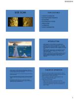
Many scholars have studied the suspended submarine pipeline treatment method, and most of them have been applied to engineering practice, including: throwing sandbags combined with covering layer, underwater short pile support, throwing sandbags combined with bionic grass cover, underwater pile combined with bionic grass cover, etc. [1-3]. According to the different forms of underwater structures after treatment, the above-mentioned treatment methods are divided into two types: non-permeable treatment and permeable treatment. Taking the method of "throwing sandbags combined with covering layer" as an example, a sandbags with a weight of about 30 kg was thrown around the suspended pipeline. During the process of throwing and filling the sandbags, the diver arranged the sandbags to ensure that the bottom of the suspended pipeline was filled with sandbags. After the sandbags were finished, the covering layer was laid on the pipeline. Obviously, after the treatment of "throwing sandbags combined with covering layer", the gap between pipeline and seabed are filled, forming a non-permeable structure. The principle of the underwater short pile support method is to set up support brackets in the suspension section of pipeline to reduce the amplitude of lateral and longitudinal vibration and prevent the pipeline from breaking caused by vortex-induced vibration under the action of current. The principle of the underwater short pile support method is to install support brackets in the suspended section of pipeline to reduce the amplitude of lateral and longitudinal vibration and prevent the pipeline from breaking due to vortex-induced vibration under the action of current. The specific way is to install underwater short pile support alternately along the suspended pipeline to shorten the suspended span of pipeline. the underwater short pile is about 15 m into the soil and every underwater short pile has a cantilever beam near the sea pipe. It can be seen that after the "underwater short pile support" method, there are still gaps between the pipeline and the seabed, which is a permeable structure. The actual effect of non-permeable treatment and permeable treatment can be detected by side scan sonar. 3. The principle of side scan sonar detection Side scan sonar technology uses the backscattering principle of incident acoustic beam to detect the shape of the object. It can provide a more intuitive acoustic image of the object. Side scan sonar transmits fan-shaped beam to the left and right sides of the sonar linear array, and the backscattering signal is received by the sonar linear array in time. The object with a certain height can produce "shadow" on the acoustic reflection image [4-7]. By analysing the "shadows" in acoustic reflection image under different imaging conditions, it can be judged whether the submarine pipeline is permeable or non-permeable, and the treatment effect of suspended pipeline can be evaluated. When the submarine pipeline is suspended, the lateral emitted sonar beam first meets the pipeline, because of its shortest reflection distance, it first forms strong reflection on the sonar image. The gap between the bottom of the submarine pipeline and the seabed (the height of the gap is the height of the suspension) allows the sonar beam to pass through and form an "acoustic permeability zone", which is located outside the strong reflection of the pipeline on the sonar image. The pipeline blocks some sonar beam from passing through and forms an "acoustic shadow zone" with the longest reflection distance, which is located outside the "acoustic permeability zone" on the sonar image. Thus, the sonar image formed by the suspended pipelines are in the order of strong reflection of pipeline, "acoustic permeability zone" and "acoustic shadow zone" (Figure 1a). When the suspended pipeline is treated by non-permeable method, the lateral emitted sonar beam first meets the pipeline and the sandbags supporting the pipeline, because of its shortest reflection distance, it first forms strong reflection on the sonar image. The pipeline and sandbags block some sonar beam from passing through and forms an "acoustic shadow zone" with the longest reflection distance, which is located outside the strong reflection on the sonar map. Thus, the sonar image formed by the suspended pipelines after non-permeable treatment are in the order of strong reflection of pipeline and sandbags, "acoustic shadow zone" (Figure 1b).
2
AEMCME 2018 IOP Publishing IOP Conf. Series: Materials Science and Engineering 439 (2018) 032068 doi:10.1088/1757-899X/439/3/032068 1234567890‘’“”
a. Side scan sonar detection for pipeline suspension
b. Side scan sonar detection of suspended pipeline after non-permeable treatment Figure 1. Principle of side scan sonar detection before and after suspended submarine pipeline treatment The beam path and sonar pattern shown in Figure 1b will be produced when the treatment method of underwater short pile support" is used. The reflection characteristics of the area between the two piles are equivalent to the detection results when the pipelines are suspended in Figure 1a.
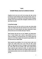
4. Engineering example When side scan sonar is used, a higher resolution can be obtained by choosing a higher frequency. A clearer sonar image can be obtained by choosing a shorter detection range and setting a smaller survey range. However, not the detection effect is sure to be better when the detection distance is getting closer. The experiment reveals that the detection effect for suspended pipeline is best when the angle between the acoustic beam and the seabed is kept at about 20 degree [8]. In addition, in some cases, when there is a pit on the seabed beneath the pipeline, its reflection characteristics are easy to be confused with the "shadow" of the pipeline on the sonar image. Then it can be detected in different directions and distances around the suspended pipeline to obtain abundant detection data and make correct interpretation. 4.1. Detection results after non-permeable treatment The detection example after the treatment of "throwing sandbags combined with covering layer " method is shown in Figure 2. It can be seen that the treated pipeline suspended section always forms "acoustic shadow zone" along the direction of the sonar beam emission, which is characterized by the reflection of the energy blank and the "acoustic shadow zone" is variable in size, which is related to the detection angle, the relative position of the line and the pipeline, and so on. This further shows that it is not the reflection characteristics of the topography such as the seabed depression. In addition, the suspended pipeline section after treatment changes from the original uniform strong reflection image to a granular non-uniform reflection, which is the reflection characteristic of sandbags piled around the pipeline. In Fig. 2a, after measuring the water depth, the distance between pipeline and sonar trailer, the width of "shadow" and other parameters, the height of pipeline and sandbags is about 1.0 m by geometric relationship calculation. Comparing the suspended height of 0.7 m given by the data before treatment, the thickness of the overburden above the pipeline after treatment is about 0.3 m. In Fig. 2b, we can also see that there is a pipeline in suspension on the north side of the treatments pipeline, and its reflection characteristics are: there is a section of "acoustic permeability zone" about 2 m wide outside the strong reflection area of the pipeline, and then the outer side is "acoustic shadow zone". The suspended height can be calculated to be about 0.7 m based on geometric relations.
3
AEMCME 2018 IOP Publishing IOP Conf. Series: Materials Science and Engineering 439 (2018) 032068 doi:10.1088/1757-899X/439/3/032068 1234567890‘’“”
a. The sweep range is 50 m, the survey line is parallel to the treatment pipeline.
b. The sweep range is 75 m, the survey line is oblique crossing to the treatment pipeline.
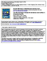
Figure 2. Side scan sonar detection image after non-permeable treatment 4.2. Detection results after permeable treatment Figure 3 is an example of test after treatment of underwater short pile support. It can be seen that a total of four underwater steel pipe piles were drilled into the suspended section of the marine pipeline, and the underwater steel pipe piles were alternately arranged on both sides of the suspended pipeline. Four underwater short piles divided the suspended section into five small sections, effectively reducing the suspended span length and reducing the risk of damage of the pipeline after vortexinduced vibration. In sonar images, the strong reflection of steel pipe piles intersects with the strong reflection of pipelines, reflecting the contact relationship between steel pipe piles and pipelines. The strong reflection of steel pipe piles is "shadow" outside, and there is a certain width of "acoustic permeability zone" between the strong reflection of pipelines and "shadow". The width of the "acoustic permeability zone" in Figure 3 is larger. The calculation of geometric relationship shows that the maximum suspended height of the pipeline is about 1.9 m, and the suspended condition is serious.
Figure 3. Side scan sonar detection image after permeable treatment
4
AEMCME 2018 IOP Publishing IOP Conf. Series: Materials Science and Engineering 439 (2018) 032068 doi:10.1088/1757-899X/439/3/032068 1234567890‘’“”
5. Conclusion In this paper, the imaging principle of side scan sonar for detecting submarine objects is analysed, the application of side scan sonar in the detection of suspension and treatment effect of submarine pipelines is discussed, and the detection results and interpretation are illustrated. The detection application of side scan sonar in the non-permeable and permeable treatment of submarine suspended pipeline are furtherly illustrated with the examples of "sandbags combined with covering layer" and "underwater short pile support". The sonar image formed by the suspended pipelines after non-permeable treatment are in the order of strong reflection of pipeline and sandbags, "acoustic permeability zone" and "acoustic shadow zone". The sonar image formed by the suspended pipelines after permeable treatment are in the order of strong reflection of pipeline and sandbags, "acoustic shadow zone". Side scan sonar detection technology is effective and feasible in detecting the effect of suspended pipeline treatment. It is helpful to reduce the misjudgement by using scanning sonar to detect the suspended pipeline in different directions and at different distances. Acknowledgments The study was supported by the Basic research business fees of Central Research Institutes of TIWTE (No. TKS170212). References [1] Miao Wencheng. (2004) Analysis and Settlement of Hidden Trouble of Pipeline on Chengdao Seabed. Petroleum Engineering Construction., 30(3): 40–58. [2] Meng Fansheng, Xu Aimin, Li Jun. (2006) Control of Hanging Problem of Offshore Subsea Pipeline. China Offshore Platform., 21(1): 52–54. [3] Yang Baozhen. (2009) Suspension Hazard of Submarine Pipeling Risers and Treatment Problem. Shipbuilding of China, 50(2): 621–627. [4] Xu Feng, Cong Hongwen. (2001) Acoustic image Analysis of Side Scan Sonar. Hydrographic Surveying and Charting, 1:58–61. [5] Yang Kun, Sun Yanjun, Sui Haichen. (2003) Application of Investigation of Sub-bottom Profile Sidescan Sonar in Boxi Oil Field Project. Journal of Waterway and Harbour, 1:43– 47. [6] Zhou Xinghua, Jiang Xiaojun, Shi Yongzhong. (2007) Application of Side Scan Sonar and Sub-bottom Profile in the Checking of Submerged Pipeline in Hangzhou Bay. Hydrographic Surveying and Charting, 4:64–67. [7] Wei Ronghao, Chen Tiexin, Guo Chen. (2014) Application of Side scan Sonar in Suspended Submarine Pipeline Investigation. Hydrographic Surveying and Charting, 34(2):63–65. [8] Jiang Junjie, Tang Minqiang, Zheng Xilai. (2008) Application of Side scan Sonar in Suspended Submarine Pipeline Investigation. China Science and Technology information, 14:49–5.1
5