![Air Circuit Breaker-Chint [PDF]](https://pdfs.asia/img/200x200/air-circuit-breaker-chint.jpg)
8 0 3 MB
Air Circuit Breaker
NA1 NA1-1000 200A to 1000A
NA1-2000 630A to 2000A
Summary 5 basic frame sizes For your various requirements, the Air Circuit Breaker NA1 includes 5 basic frame sizes as followed.
NA1-3200, 4000 2000A to 4000A
NA1-6300 4000A to 6300A
C-71
> >>
Air Circuit Breaker
NA1 1. General
2.6 Type designation
1.1 Application scope NA1 series air circuit breaker is suitable for the circuit of AC 50Hz/60Hz with rated service voltage 400V, 690V and rated service current up to 6300A. It is mainly used to distribute electric energy and protect circuits and electric equipment against over-load, under-voltage, short-circuit and single-phase earthing fault. With intelligentized and selective protection functions, the breaker can improve the reliability of power supply, and avoid unnecessary power failure. The breaker is applicable for power stations, factories, mines (for 690V) and modern high-buildings, especially for the distribution system of intelligentized building. 1.2 Standard: IEC/EN 60947-2.
NA1 - □-□□ / □-□-□-□-□ Voltage of secondary circuit AC220V, AC380V, AC230V, AC400V DC220V, DC110V Wiring of main circuit: H:Horizontal wiring of main circuit V:Vertical wiring of main circuit Mode of installation: F:Fixed type D:Draweout type
2. Operation conditions
C
Mode of operation: M:Manual P: Power-driven
2.1 Temperature condition: -5℃~40℃; the average value within 24h shall not exceed +35℃ (special situation excluded); 2.2 Altitude:≤2000m; 2.3 Pollution grade: Grade 3; 2.4 Air conditions: At mounting site, relative humidity not exceed 50% at the max temperature of +40℃, higher relative humidity is allowable under lower temperature, RH could be 90% at +20℃, special measures should be taken to occurrence of dews; 2.5 Note: Without the intelligent controller, the breaker functions as a switch-disconnector.
No. of poles: 3:3-pole 4:4-pole Intelligent controller: M: Standard type 3M: Multifunctional type 3H: Communication type Rated current: Frame size rated current
Rated current 200A 400A
1000A
630A 800A 1000A 630A 800A
2000A
1000A 1250A 1600A 2000A
3200A
2000A 2500A
4000A 4000A
3200A 4000A 4000A
6300A
5000A 6300A
Frame size rated current: 1000A, 2000A, 3200A,4000A, 6300A Design sequence number ACB Company code
> >>
C-72
Air Circuit Breaker
NA1
11
7
12
8
13
14
1
15 3
4
5
C-73
> >>
Air Circuit Breaker
NA1
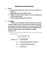
NA1 Air Circuit Breaker 1
Drawout type
2
Fixed type
3
Intelligent controller
4
Operating mechanism
5
Auxiliary contact
6
Locking-device
7
Arcing chamber
8
Secondary connecting part
9
Wire-cable mechanical interlock
C
9 10
10 Connecting-rod type mechanical interlock 11 Shunt release 12 Closing electromagnet 13 Under-voltage release 14 Motor-driven energy-storage mechanism 15 Rotary handle 16 Fixed plate
2
16
6
> >>
C-74
Air Circuit Breaker
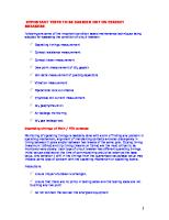
NA1 3. Structure
=
+ Drawer seat
Body Drawout type breaker/switch-disconnector
Fixed plate for the fixed type breaker Fixed type breaker/switch-disconnector
Fault-breaking indicator reset button
Enclosure
Under-voltage release
Making button
Breaking button
Energy storage & release indicator
Breaking/making indicator
Name plate
Shunt release Closing electromagnet Auxiliary contact
Structure for in and out
Rotary handle
Motor-driven energy storage mechanism
Locking device
Rotate out Rotate in
C-75
> >>
Intelligent controller
Air Circuit Breaker
NA1 4. Main technical parameter Type
NA1-1000
Rated ultimate short circuit breaking capacity
Icu=42kA
400V
25kA
690V
Rated service short circuit breaking capacity
Ics=30kA
400V
20kA
690V
Rated short-time withstand current
Icw=30kA / 1s 400V
Rated current
In (A)
200
400
630
Number of poles
C
20kA / 1s 690V 800
1000
3, 4
Rated voltage Ue (V)
400, 690
Rated insulation voltage Ui (V)
800
Rated current of N-pole In (A)
50%In
Fixed disconnection time (ms)
23~32
Standard type (M)
Intelligent controller
Communication type (H) 5000
Electric life
Operation performance
Non-maintenance 10,000
Mechanical life
Maintenance
Connection pattern
20,000
Horizontal, Vertical
Motor operational standard configuration weight (kg)
Drawout 3P/4P
38/55
Fixed 3P/4P
22/26.5
Standard configuration: M type intelligent controller; Under-voltage release; Shunt release; Motor-driven energy-storage mechanism
Type
NA1-2000
Rated ultimate short circuit breaking capacity
Icu=80kA
400V
50kA
690V
Rated service short circuit breaking capacity
Ics=50kA
400V
40kA
690V
Rated short-time withstand current
Icw=50kA / 1s 400V
Rated current
In (A)
630
Number of poles
800
1000
1250
1000
Rated current of N-pole In (A)
50%In
Fixed disconnection time (ms)
23~32
Standard type (M) Communication type (H) 5000
Electric life
Non-maintenance 10,000
Mechanical life
Maintenance
Connection pattern Motor operational standard configuration weight (kg)
2000
400, 690
Rated insulation voltage Ui (V)
Operation performance
1600
3, 4
Rated voltage Ue (V)
Intelligent controller
40kA / 1s 690V
20,000
Horizontal, Vertical Drawout 3P/4P
67.5 / 79.8
69.6 / 83.65
78.6 / 90.5
Fixed 3P/4P
42.4 / 52
44 / 54
45 / 56
> >>
C-76
Air Circuit Breaker
NA1 Type
NA1-3200, NA1-4000
Rated ultimate short circuit breaking capacity
Icu=80kA
400V
65kA
690V
Rated service short circuit breaking capacity
Ics=65kA
400V
65kA
690V
Rated short-time withstand current
Icw=65kA / 1s 400V
Rated current
In (A)
2000
50kA / 1s 690V
2500
Number of poles
3200
4000
3, 4
3
Rated voltage Ue (V)
400, 690
Rated insulation voltage Ui (V)
1000
Rated current of N-pole In (A)
100%In
Fixed disconnection time (ms)
23~32
Standard type (M)
Intelligent controller
Communication type (H) 5000
Electric life
Operation performance
Non-maintenance 10,000
Mechanical life
Maintenance
Connection pattern
20,000
Horizontal, Vertical
Motor operational standard configuration weight (kg)
Drawout 3P/4P
90.5 / 116
90.5 / 116
102.8 / 131
132 / 172
Fixed 3P/4P
54.8 / 68
54.8 / 68
56.5 / 86
85 / -
Standard configuration: M type intelligent controller; Under-voltage release; Shunt release; Motor-driven energy-storage mechanism
Type
NA1-6300
Rated ultimate short circuit breaking capacity
Icu=120kA
400V
85kA
690V
Rated service short circuit breaking capacity
Ics=100kA
400V
75kA
690V
Rated short-time withstand current
Icw=100kA / 1s 400V
rated current
In (A)
4000
Number of poles
5000
3 400, 690
Rated insulation voltage Ui (V)
1000
Rated current of N-pole In (A)
100%In
Fixed disconnection time (ms)
23~32
Operation performance
Standard type (M) Communication type (H) 2500
Electric life
Non-maintenance 5000
Mechanical life
Maintenance
Connection pattern Motor operational standard configuration weight (kg)
C-77
> >>
6300
3, 4
Rated voltage Ue (V)
Intelligent controller
75kA / 1s 690V
10,000
Horizontal, Vertical Drawout 3P/4P
202 / 236
202 / 236
236 / -
Fixed 3P/4P
-/-
-/-
-/-
Air Circuit Breaker
NA1 5. Dimensions and connection NA1-1000 Drawout-type 216
34
Boring dimension of doorcase
268 226
Installation panel
91.5
5
358
304
316
8×φ5
101.5
362
H
N
L1 L
70
158
C
Installation hole on right side
65
323
Connected position
70 n×φ13
35 15
35
18
12
Disconnected position
27 70
12
105 A
N
200,400A
16
45
n×φ10.5 630,800, 1000A
158
2×φ8.5 2-11.5×8.5
NA1-1000
L1
L
3P
194
284
4P
264
354
In(A)
A(mm)
n(3P/4P)
H(mm)
200, 400
32
3/4
6
630
50
6/8
8
800, 1000
50
6/8
10
L1(3P)
L1(4P)
NA1-1000 Fixed-type
Boring dimension of doorcase
H
268
N
259
Installation panel
70
70
9
A
239
3
15
216
N
2
46.5
312
8×φ5 270
101.5
315
226
Installation hole on right side
70
12 200,400A
n×φ13
35
12
18
15
35
53
144
12
630,800, 1000A
4-9×13
n×φ10.5
NA1-1000
L1
In(A)
A(mm)
n(3P/4P)
H(mm)
3P
246 274
200, 400
32
3/4
6
4P
316 344
630
50
6/8
8
800, 1000
50
6/8
10
L
L1
L
> >>
C-78
Air Circuit Breaker
NA1 NA1-2000 Drawout-type 45(Disconnected position)
448(4P) a
353(3P)
N pole
258
439
42.5
95
92.5
30
N pole
60
14
37
95
16×Φ13
70 175
67
187.5
383.5
30
97
14
37.5
a
112 92
95
horizontal connection(Default Configuration)
23
10
8×Φ13
60
28
292
465
375(3P)
95
470(4P)
95
95
92.5
268
378
40
17
Φ14
11×Φ5 175
N pole 115
2×11×17
55
302
47 20
265(3P)
360(4P)
Φ11
302
155
21.5
horizontal connection Lengthen busbar
172
Installation panel 32×Φ13
187.5
Right & outer side of breaker
344
33
Right & outer side of breaker
28 60 95
95
95
L type Horizontal Connection
Opening hole on panel
In A
a mm
630
10
800~1600 15 2000
20
NA1-2000 Drawout-type, vertical, rear connection 448(4P)
45(Disconnected position)
353(3P)
C Direction
97
175
10
187.5
14
439
292 375(3P)
55
438.5
37
10
70
95.5
42.5
122.5
258
60
28
4×Φ13
Φ14
378
268 2×11×17
302
47 20
265(3P)
360(4P)
Φ11
302
155
21.5
470(4P)
In A
a mm
630
10
800~1600
15
2000
20
55
C Direction 172
11×Φ5 175
33
344 187.5
Installation panel
a
N pole
Right & outer side of breaker
Right & outer side of breaker
Opening hole on panel
C-79
> >>
95
95
95
92.5
Air Circuit Breaker
NA1 NA1-2000 Drawout-type, horizontal, rear connection 448(4P)
45(Disconnected position)
353(3P)
37
187.5
175 438.5
268
439
a mm
630
10
800~1600
15
2000
20
378
302
In A
C Direction
47 20
265(3P)
2×11×17 Φ14
60
Installation panel
344
33
Right & outer side of breaker
187.5
Right & outer side of breaker
8×Φ13
55
172
11×Φ5
28
10
55
N pole
95
95
92.5
95
Opening hole on panel
NA1-2000 Fixed-type 413(4P)
18min
Zero arcing covering ferreous material
318(3P) 292
28
115
17 95
258
112
95
435(4P)
311.2
86
95
N pole
17 Installation hole on Right & outer side of breaker
2
342.2
Opening hole on panel
Installation panel
8×Φ13
60
95
95
86
horizontal connection shortened busbar
115
269 Installation hole on Right & outer side of breaker
95
horizontal connection Lengthen busbar
28.5
150
8×Φ5
340(3P)
95
28
N pole
30
340(3P) 435(4P)
300
60
67
21 11 181
359
30
N pole
13
11
290
4×Φ12
86
b
55 69.5
95
16×Φ13
60
150
95
horizontal connection (Default Configuration)
32
a
402
a
50
8×Φ13
60
42
N pole
40
360(4P)
302
155
21.5
470(4P)
Φ11
175
C
292 375(3P)
14
97
14
10
70
95.5
42.5
122.5
258
a
C Direction
In A
a mm b mm
630
10
17
800~1600 15
17
2000
18.5
20
28 60
32×Φ13 95
95
95
L type Horizontal Connection
> >>
C-80
Air Circuit Breaker
NA1 NA1-3200 Drawout-type
100
45(Disconnected position)
16×Φ13
100
50
25
N Pole
528(4P) 413(3P)
50
a
125
125
92.5
439
70
37.5
352
491
25
75
14
37 92
175
100 16×Φ13
217.5
23
97
10
horizontal connection(Default Configuration)
42.5
112
258
a
125
435(3P)
536
550(4P)
125
125
125
92.5
55
202
11×Φ5 33
Installation panel
404
Right & outer side of breaker
Right & outer side of breaker
217.5
40
115
N Pole
17
2×11×17 Φ14
175
378
362
47 20
325(3P)
440(4P)
Φ11
302
268
155
21.5
horizontal connection shorten busbar
a mm
2000~2500
20
3200
30
40 100
32×Φ13 115
Opening hole on panel
In A
125
125
L type vertical connection
NA1-3200 Drawout-type, horizontal, rear connection
528(4P)
45(Disconnected position)
413(3P)
C Direction
97
175
439
37
10
70
100
100
42.5
126
258
50
8×Φ13
20
217.5
40
352 435(3P)
94 495
In A
a mm
2000~2500
20
3200
30
2×11×17
55
Φ14
175
Right & outer side of breaker
302 202
11×Φ5 33
404 217.5
Opening hole on panel
C-81
> >>
N pole
378
362
C Direction
a
47 20
268
Φ11 325(3P)
440(4P)
155
21.5
550(4P)
Installation panel Right & outer side of breaker
115
115
115
102.5
Air Circuit Breaker
NA1 NA1-3200 Drawout-type, horizontal, rear connection 528(4P)
45(Disconnected position)
413(3P)
97
439
37
10
70
107.5
42.5
112
258
a
C Direction
175
C
217.5 352 435(3P)
495
a mm
2000~2500
20
3200
30
302
268
378
362
202
11×Φ5 33
404
Right & outer side of breaker
217.5
Right & outer side of breaker
N pole
100
50
Installation panel 94
55
20
C Direction 40
2×11×17 Φ14
175
In A
47 20
Φ11 325(3P)
440(4P)
155
21.5
550(4P)
16×Φ13 115
Opening hole on panel
125
125
92.5
NA1-3200 Fixed-type
Zero arcing covering
493(4P) 378(3P)
N pole
16×Φ13
86
40
40
72
352
15
18min
ferreous material
402
115
11 211
389
13
11
290
115
96
12×Φ13 18.5
86
50
32
21
N pole
60
69.5
150
115
400(3P)
115
115
96
horizontal connection shorten busbar
115
362
28.5
Installation hole on
400(3P)
Installation hole on Right & outer side of breaker
404
2
In A
a mm
2000~2500
20
3200
30
40 86
32×Φ13
8×Φ5 Right & outer side of breaker 202
515(4P)
40
4×Φ12
N pole
15
269
311
515(4P)
150
50
115
horizontal connection(Default Configuration)
55
258
112
a
115
a
115
115
115
Installation panel
L type vertical connection
Opening hole on panel
> >>
C-82
Air Circuit Breaker
NA1 NA1-4000 Fixed-type (3P) 493 134
40
10
ferreous material
16×Φ13
120
15
15
18min
Zero arcing covering
352
130
189.5
79
21
258
402 130
11
11
13
69.5
150
50
189.5
Horizontal
55
112
30
40
15
290
515
424
311
269
4×Φ12
17
40
175
479
50 24×Φ15
28.5
150
362
140 8×Φ5
202
2
Installation hole on
515
Right & outer side of breaker
Installation panel
207.5
207.5
Installation hole on Right & outer side of breaker
404
Vertical
Opening hole on panel
NA1-4000 Drawout-type (3P) 45(Disconnected position)
97
258 37
10
70
92
42.5
112
439
30
528
175 217.5 494
352
378
103
302
362
20
440
268
Φ11
40
155
20
21.5
550
12×Φ13
2×11×17
50
47
Φ14 55
140
175
202
11×Φ5
33
Right & outer side of breaker
404 217.5
Opening hole on panel
C-83
> >>
Installation panel Right & outer side of breaker
197.5
197.5
77.5
Air Circuit Breaker
NA1 NA1-4000 Drawout-type (4P) 756
45(Disconnected position)
92 97
175
C
37
10
439 70
42.5
112
258
20
C Direction
187.5 292
490
155
21.5
788
302
16×Φ13
155
40
N Pole
20
C Direction 378
302
20
678
268
Φ11
55
Φ14
175
103
47
2×11×17
172
11×Φ5 33
Installation panel
344
Right & outer side of breaker
187.5
Right & outer side of breaker
80
50 142.5
206.5
206.5
140
Opening hole on panel
NA1-6300 (In=4000A,5000A) Drawout-type
903(4P)
45(Disconnected position)
258
92
70
37
42.5
112
439
30
798(3P)
217.5
10
97
352
175 813(3P)
494
302
362
378
268
Φ11
N Pole 100
202
55
11×Φ5
33
404 217.5
220
40
103
Φ14
175
28×Φ15 155
47
2×11×17
20
20
703(3P)
818(4P)
155
21.5
928(4P)
Opening hole on panel Right & outer side of breaker
Right & outer side of breaker
55 178
247
247
164
Opening hole on panel
> >>
C-84
Air Circuit Breaker
NA1 NA1-6300 (In=6300A) Drawout-type (3P) 45(Disconnected position)
258 42.5 70
92
37
112
439
30
903
10
97
175
217.5 352
494
155
21.5
928
180
260
40
103
20
302 378
362
20
818
268
Φ11
47
2×11×17
55
Φ14
175
24×Φ15 202
11×Φ5
33
Right & outer side of breaker
404 217.5
Opening hole on panel
C-85
> >>
Installation panel Right & outer side of breaker
80 320
320
140
Air Circuit Breaker
NA1 6. Secondary circuit wiring Standard type, type (M)
6.1 NA1-1000
Intelligent controller
Main circuit
Auxiliary contact
Emergency break
Motor-driven Motor-driven make break
Motor-driven energy-storage
Auxiliary contact
SB1 SB2 SB3 HL1
HL2
HL3
▲ 3
5
7
9
14
15
19
17
21
23
25
27
29
33 35
31
37
C
39 XT
FU
Intelligent controller
Q
DF1
DF2
F
X
M
Power of control circuit
DF3
DF4 SA
TA FU 1
2
+
-
DC24V
4
6
8
10
11
12
13
16
18
20
22
24
26
28
30
32
34
36
38
40 XT
Power module
Hl1: Failure indicator HL2: Close indicator HL3: Energy storage indicator SB1: Under-voltage button SB2: Shunt button SB3: Close button Q: Under-voltage release F: Shunt release X: Close electromagnet M: Energy storage motor DF1-F4: Auxiliary switch 1#, 2#: Auxiliary power input(DC24V) 3#,4#,5#: Fault trip contact output(4# common terminal, contact capacity AC230V,5A 6#,7#: To be connected with current transformer(selective)
8#,9#: Making indicator (capacity AC400V,1A) 10#: Over-current pre-alarm signal output (selective) # 11 : Short current trip signal output (selective) 12#: Earthing trip alarm output (selective) 13#: Self-checking alarm signal output (selective) # 14 : Common line of different contacts 15#: Earthing protection line 16#,17#: Normal contact of the controller (contact capacity AC400V 1A) 27#,28#: Under-voltage release 29#,30#: Shunt release # # 31 ,32 : Closing electromagnet # 33 ,34#,35#: Energy storage motor 18#~26#, 38#~40#: Auxiliary contact (auxiliary contact capacity: AC230V,5A)
Note: Dashed is to be connected by users.
> >>
C-86
Air Circuit Breaker
NA1 Communication type, type (H)
L1 N PE
Emergenay break
Intelligent controller
Main circuit
Motor-driven break
Motor-driven make
Auxiliary switch
FU
L
Profibus-DP
N
PE
ST-4 Power module -
ST-DP Device
12 13
Fault indicator
-
+
14 15
-
+
16 17
-
HL3
+
18 19
1 2 3 4 5 6 7 8 9 10 11 D11D12 D13 + + DC24V COM ST201
Green HL1
+
HL2
D01
D02
D03
12 13
14 15
16 17
SB1 SB2 SB3
▲
Red
3
5
7
9
11
13
15
17
19
21
23
25
Intelligent controller
27
29
31
Q
F
X
33
35
39 XT
37
M
DF1
DF2
DF3
SA
TA
1
DC24V
+
2
4
6
8
10
12
14
16
18
20
22
24
26
28
30
32
34
36
38
40 XT
-
Power module
Hl1: Failure indicator HL2: Close indicator HL3: Energy storage indicator SB1: Under-voltage button SB2: Shunt button SB3: Close button Q: Under-voltage release F: Shunt release X: Close electromagnet M: Energy storage motor DF1-F4: Auxiliary switch 1#, 2#: Auxiliary power input(DC24V) # # # # 3 ,4 ,5 : Fault trip contact output(4 common terminal, contact capacity AC230V,5A 6#, 7#: To be connected with current transformer(N/O auxiliary contact, capacity AC400V, 1A,when no current transformer)
Note: Dashed is to be connected by users.
C-87
> >>
8#,9#: Making indicator(capacity AC400V,1A) 10#, 11#: communication output # # 12 , 13 : Signal alarm of load 1 output # 14 , 15#: Signal alarm of load 2 output 16#, 17#: Making signal output # # 18 , 19 : Closing signal output 20#: Communication shield ground line 21#~24#: Voltage signal input of phase N,A,B,C # # 25 , 26 : Auxiliary contact (capacity:AC230V,5A) 27#,28#: Under-voltage release 29#,30#: Shunt release # # 31 ,32 : Closing electromagnet # 33 ,34#,35#: Energy storage motor 36#~40#: Auxiliary contact (capacity:AC230V,5A)
Air Circuit Breaker
NA1 3NO(normal open) 3NC (normal close) standard type (M)
Main circuit
Auxiliary contact
Intelligent controller
Emergency Motor-driven Motor-driven break break make
Motor-driven energy-storage
Auxiliary contact
SB1 SB2 SB3 HL1
HL2
HL3
C
▲ 3
5
7
14
9
15
17
19
21
23
25
27
29
31
33
37
35
39 XT
FU
Q Intelligent controller
DF5
DF6
DF1
DF2
F
M
X
Power of control circuit
DF3 DF4
SA
TA FU
DC24V
1
2
+
-
4
6
8
10
11
12
13
16
18
20
22
24
26
28
30
32
34
36
38
40
XT
Power module
Hl1: Failure indicator HL2: Close indicator HL3: Energy storage indicator SB1: Under-voltage button SB2: Shunt button SB3: Close button Q: Under-voltage release F: Shunt release X: Close release M: Energy storage motor DF1-DF4: Auxiliary switch 1#, 2#: Auxiliary power input(DC24V) # # # # 3 ,4 ,5 : Fault trip contact output(4 common terminal,contact capacity AC230V,5A 6#, 7#: to be connected with current transformer(selective)
8#,9#: Making indicator (capacity AC400V,1A) 12#~26#: Auxiliary contact(auxiliary contact capacity: AC230V,5A) 27#,28#: Under-voltage release 29#,30#: Shunt release 31#,32#: Closing release 33#,34#:Energy storage indicator 34#,35#: Energy storage motor 38#~40#: Auxiliary contact(auxiliary contact capacity: AC230V,5A)
Note: 6NO(normal open) 6NC(normal close), without any additional function. Dashed is to be connected by users.
> >>
C-88
Air Circuit Breaker
NA1 6.2 NA1-2000~6300 The secondary circuit wiring for NA1-2000~3600 with standard type (M) intelligent controller and instantaneous under-voltage release
Emergency break
Over-current release
Main circuit
Auxiliary contact
Motor-driven Motor-driven make break
SB2
Failure 3
5
7
9
Energy storage
SB1 SB3 11 13 15 17 19 21 23
25 27
29
31 33 35
F
X
36
38
40
42
44
46
48 50
FU Q
M
AX
Power
SA
Processing unit
Intelligent Controller
FU
1
4
2
6
8
10
26 28
12 14 16 18 20 22 24
30
32
34
37
39
41
43
45
47
Open
49
51
Close
_ 110V ~ _ 220V Intelligent release power ("1" connect positive pole, and "2" connect negative pole for direct current) ~ ~380V
The auxiliary contact modes for customer use Ⅰ Four switch contact (acquiescence) 36
38
37
40
39
41
42
44
43
46
45
47
Ⅱ Five switch contact 36
38
37
40
39
41
42
44
43
46
45
47
48
50
49
SB1: Shunt button SB2: Under-voltage button SB3: Making button Q: Under-voltage release F: Shunt release X: Closing electromagnet M: Energy storage motor XT: Connection terminal SA: Position switch Note: If control voltage of Q, F, X is different from each other, they can be connected to different power. # # 1 ,2 : Auxiliary power input # # # 3 ,4 ,5 : Fault trip contact output(4# common terminal) # # # # 6 ,7 ,8 ,9 : Auxiliary contact, normal open, # # 10 ~24 : empty # # 25 ,26 : to be connected with current transformer(selective) # # 27 ,28 : Under-voltage release # # 29 ,30 : Shunt release # # 31 ,32 : Closing release # # 33 ,34 : Energy storage indicator # # 34 ,35 : Energy storage motor # # 36 ,51 : Auxiliary contact
Circuit explanation for signal output: a. Broken-line parts shall be provided by customers. # # b. Terminals 6 ,7 can output NC (normal close) contact if that is required by users. # c. Terminal 35 can be directly connected to power (automatic pre-storing energy), alternatively connect power after connecting NO button (manual-controlled pre-storing energy). d. Terminals 21#~24# is only for wiring with function meter display. (excluding the special wiring)
C-89
> >>
Air Circuit Breaker
NA1 The secondary circuit wiring for NA1-2000~6300 with type (3M) intelligent controller and instantaneous under-voltage release 2
1
L1 N PE
to the incoming-line side PE Un U1 U2 U3
SB2 SB1 SB3
C
Transformer connected
2
4
6
8
10
12
14
16
18
20
22
24
26
28
30
32
Q
F
X
34
36
38
40
42
44
46
48
50
47
49
51
SA
AX M
1
5
3
7
9
11
13
15
17
19
21
23
25
27
29
31
33
Main circuit
Shunt Closing Undervoltage release release electromagnet
Intelligent controller
The auxiliary contact modes for customer use Ⅰ Four switch contact (acquiescence) 36 38
40 42 44
37 39 41
#
#
#
46
4 3 45 47
35
37
39
41
43
Energystorage
Fault
Ⅱ Five switch contact 36 3 8
40 4 2 44
37 39 41
#
46
48 50
43 45 47
49
Energy- Energystorage storage indication motor
45
Open Close
Auxiliary switch
SB1: Shunt button SB2: Under-voltage button SB3: Making button Q: Under-voltage release F: Shunt release X: Closing release M: Energy storage motor XT: connection terminal SA: Position switch 1#, 2#: Intelligent controller power input Note: When the power supply of the intelligent controller is AC power, the 1#~2# connects to the AC power directly. When the power supply is DC power, forbid connecting the 1#~2# to the DC power directly. Add a DC power supply module, then the DC power connect to the input terminal of the DC power supply module, and the 1#~2# connect to the output terminal of the DC power supply module, or else the intelligent controller will be damaged.
3 ,4 ,5 : Fault trip contact output(4 common terminal) # # # # 6 ,7 ,8 ,9 : Auxiliary contact(normal open) # # 10 ~11 : empty # # 12 ~19 : The programmable output terminal. The normal products without these terminals, but if the customer special ordered, the cost extra added.
3M type acquiescence output: # # # # 12 ,13 : Signal alarm of load 1 output; 14 ,15 : Signal alarm of load2 output # # # # # # # 16 ,17 : Self-diagnose alarm; 18 ,19 : Fault trip; 20 : PE line; 21 ~24 : Display the voltage of the signal input. The normal products without these terminals, if the customer special ordered the function meter, the cost extra added. # 21 : N phase input terminal # # # 22 ,23 ,24 : A, B, C three phase power input terminal (note the sequence) # # 25 ,26 : Connect to the N phase current transformer or the input terminal of the current leakage transformer. The normal products without these terminals, if the customer special ordered, the cost extra added. # # # # # # # # 27 ,28 : Under-voltage release; 29 ,30 : Shunt release; 31 ,32 : Closing release; 33 ,34 : Energy storage indicator # # # # 34 ,35 : Energy storage motor; 36 ~51 : Auxiliary contact
Note: a. Red colored part is to be connected by users b. When the power system is three phase three wire, directly connect the Un to U2. ( If the voltage exceeds 400V, special explanation when ordered)
> >>
C-90
Air Circuit Breaker
NA1 The secondary circuit wiring for NA1-2000~6300 with type (3H) intelligent controller and instantaneous under-voltage release
L1 N PE
2
1
1 2 3 4 5 ST Power Supply L N L N PE Modular IV - + - + -+ - +
To TO3 busbar Profibus-DP
12 13
ST-DP
Special connecting wire
To the inconnecting-line side PE Un U1 U2 U3 SB2
D11D12D13 DO24VDO24VCOM ST201 DO3 DO1 12 13 14 15 16 17 18 19
SB1 SB3
Transformer connected 4
6
8
18 19
Green
Red
2
16 17
+ + 1 2 3 4 5 6 7 8 9 10 11
Device
Modbus-RTV
14 15
10
12
14
16
18
20
22
24
26
28
30
32
Q
F
X
34
36
38
40
42
44
46
48
50
47
49
51
SA
AX M
1
3
5
7
9
11
13
15
17
19
21
23
25
27
29
Main circuit
Intelligent controller
Undervoltage release
The auxiliary contact modes for customer use Ⅰ Four switch contact (acquiescence) Ⅱ Five switch contact 36 38
40 42 44
37 39 41
#
#
#
31
33
35
37
39
41
43
Energy storage
Fault
46
43 45 47
36 38
46
48 50
43 45 47
49
4 0 42 44
37 39 41
#
Shunt release
Closing EnergyEnergyelectromagnet storage storage indication motor
45
Open
Close
Auxiliary switch
SB1: Shunt button; SB2: Under-voltage button SB3: Making button; Q: Under-voltage release F: Shunt release; X: Closing release M: Energy storage motor; XT: connection terminal SA: Position switch 1#, 2#: Intelligent controller power input Note: When the power supply of the intelligent controller is AC power, the 1#~2# connects to the AC power directly. When the power supply is DC power, forbid connecting the 1#~2# to the DC power directly. Add a DC power supply module, then the DC power connect to the input terminal of the DC power supply module, and the 1#~2# connect to the output terminal of the DC power supply module, or else the intelligent controller will be damaged.
3 ,4 ,5 : Fault trip contact output(4 common terminal) # # # # 6 ,7 ,8 ,9 : Auxiliary contact(normal open) # # 10 ~11 : communication output # # # # 12 ,13 : Signal alarm of load 1 output; 14 ,15 : Signal alarm of load2 output # # # # 16 ,17 :Breaking signal output; 18 ,19 :Making signal output # # 20 : PE line; 21 : N phase input terminal # # # 22 ,23 ,24 : A, B, C three phase power input terminal (note the sequence) # # 25 26 : Connect to the N phase current transformer or the input terminal of the current leakage transformer. The normal products without these terminals, if the customer special ordered, the cost extra added. ST~DP: DP protocol module. There is no need for the ST-DP protocol module, if the communication protocol is Modbus-RTV. But when the communication protocol is Profibus-DP, the ST-DP protocol module is necessary, but the cost extra added. ST power module IV: power converter (optional components) ST201: Magnify the signal capacity of the controller. ( optional components) If the customer special ordered, the cost extra added. # # # # 27 ,28 : Under-voltage release; 29 ,30 : Shunt release # # # # 31 ,32 : Closing release; 33 ,34 : Energy storage indicator # # # # 34 ,35 : Energy storage motor; 36 ~51 : Auxiliary contact
Note: a. Red colored part is to be connected by users b. When the power system is three phase three wire, directly connect the Un to U2. (If the voltage exceeds 400V, special explanation when ordered)
C-91
> >>
Air Circuit Breaker
NA1 The secondary circuit wiring for NA1-2000~6300 with standard type (M) intelligent controller and time-delay under-voltage release
Main
Over-current release
circuit
Emergency disconnection
SB2
Motor driven break
Motor driven close
SB1 SB3
Motor driven energy storage
7 9
Auxiliary switch
Energy storage
Failure 3 5
Under-voltage time-delay release
Under-voltage time-delay controller
11 13 15 17 19 21 23
25 27 29
31 33 35
36
38
40
46 48 50
42 44
C
FU
AX Processing unit
Power
Intelligent controller
FU
4 6
1 2
8
10 12 14 16 18 20 22 24
26 28 30
32
34
37 39
41
43 45 47 Open
~_ 110V ~_ 220V
49
51
Close
Intelligent release power(”1” connect positive pole, and “2” connect negative pole for direct current)
~380V
The auxiliary contact modes for customer use Ⅰ Four switch contact (acquiescence) 38
4 0 42 44
3 9 41
#
46
48 50
43 45 47
49
SB1: Shunt button SB2: Under-voltage button SB3: Making button Q: Under-voltage time-delay release F: Shunt release X: Closing electromagnet M: Energy storage motor XT: Connection terminal SA: Position switch Note: If control voltage of Q, F, X is different from each other, they can be connected to different power.
#
1 ,2 : Auxiliary power input # # # 3 ,4 ,5 : Fault trip contact output(4# common terminal) # # # # 6 ,7 ,8 ,9 : Auxiliary contact(normal open) # # 10 ~24 : empty # # 25 ,26 : to be connected with current transformer(selective) # # 27 ,28 : Under-voltage release # # 29 ,30 : Shunt release # # 31 ,32 : Closing release # 33 ,34#: Energy storage indicator 34#,35#: Energy storage motor 36#,37#: Under-voltage time delay release 38#~51#: Auxiliary contact Circuit explanation for signal output: a. Broken-line parts shall be provided by customers. b. Terminals 6#,7# can output NC (normal close) contact if that is required by users. # c. Terminal 35 can be directly connected to power (automatic pre-storing energy), alternatively connect power after connecting NO button (manual-controlled pre-storing energy). d. The 21#~24# is only for wiring with function meter display. (Excluding the special wiring)
> >>
C-92
Air Circuit Breaker
NA1 The secondary circuit wiring for NA1-2000~6300 with type (3M) intelligent controller and time-delay under-voltage release L1 N PE
1
2
SB2 SB1 SB3 To the incoming-line side PE Un U1 U2 U3 Transformer connected
2
4
6
8
10
12
14
16
18
20
22
24
26
Under-voltage time-delay controller
28
30
32
F
X
34
36
38
40
42
44
46
48
50
47
49
51
Q
SA
AX M
1
5
3
7
9
11
13
15
17
19
21
23
25
27
29
31
33
Main circuit
Intelligent controller
The auxiliary contact modes for customer use Ⅰ Four switch contact (acquiescence) 38
#
#
#
46
48 50
43 45 47
49
4 0 4 2 44
3 9 41
35
37
Energy storage
Fault
#
Emergency break
Shunt release
EnergyClosing storage electromagnet indication
Energystorage motor
39
41
43
45
Open
Under-voltage time-delay release
Close
Auxiliary switch
SB1: Shunt button; SB2: Under-voltage button SB3: Making button; Q: Under-voltage release F: Shunt release; X: Closing release M: Energy storage motor; XT: Connection terminal SA: Position switch # # 1 , 2 : Intelligent controller power input Note: When the power supply of the intelligent controller # # is AC power, the 1 ~2 connects to the AC power directly. When the power supply is DC power, forbid connecting the # # 1 ~2 to the DC power directly. Add a DC power supply module, then the DC power connect to the input terminal # # of the DC power supply module, and the 1 ~2 connect to the output terminal of the DC power supply module, or else the intelligent controller will be damaged. #
#
#
#
3 ,4 ,5 : Fault trip contact output(4 common terminal); 6 ,7 ,8 ,9 : Auxiliary contact(normal open) # # # # 10 ~11 : empty; 12 ~19 are the programmable output terminal. The normal products without these terminals, but if the customer special ordered, the cost extra added. 3M type acquiescence output: 12#,13#: Signal alarm of load 1 output; 14#,15#: Signal alarm of load2 output # # # # 16 ,17 : Self-diagnose alarm; 18 ,19 : Fault trip # # # 20 : PE line; 21 ~24 : Display the voltage of the signal input. The normal products without these terminals, if the customer special ordered the function meter, the cost extra added. # # # # 21 : N phase input terminal; 22 ,23 ,24 : A, B, C three phase power input terminal (note the sequence) # # 25 ,26 Connect to the N phase current transformer or the input terminal of the current leakage transformer. The normal products without these terminals, if the customer special ordered, the cost extra added. # # # # 27 ,28 : Under-voltage release; 29 ,30 : Shunt release # # # # 31 ,32 : Closing release; 33 ,34 : Energy storage indicator 34#,35#: Energy storage motor; 36#,37#: Under-voltage time delay release # # 38 ~51 : Auxiliary contact
Note: a. Red colored part is to be connected by users b. When the power system is three phase three wire, directly connect the Un to U2. (If the voltage exceeds 400V, special explanation when ordered)
C-93
> >>
Air Circuit Breaker
NA1 The secondary circuit wiring for NA1-2000~6300 with type (3H) intelligent controller and time-delay under-voltage release L1 N PE
1
2
1 2 3 4 5
To TO3 busbar
12 13
ST-DP
Modbus-RTV
8
To the inconnecting-line side PE Un U1 U2 U3 Transformer connected
Green
Red 6
- +
- +
16 17
18 19
10
12
D11D12D13 DO24VDO24VCOM ST201 DO3 DO1 12 13 14 15 16 17 18 19
SB2 SB1 SB3
Special connecting wire
4
14 15
+ 1 2 3 4 5 6 7 8 9 10 11
Device
2
STPower Supply Modular IV
L N L N PE - + - +
Profibus-DP
14
16
18
20
22
24
26
C
Under-voltage time-delay controller
28
30
32
F
X
34
36
38
40
42
44
46
48
50
47
49
51
Q
SA
AX M
1
3
5
7
9
11
13
15
17
19
21
23
25
27
29
31
Fault
Intelligent controller
The auxiliary contact modes for customer use Ⅰ Four switch contact (acquiescence) 46
48 50
43 4 5 4 7
49
4 0 42 4 4
39 41
35
37
39
Energy storage
Main circuit
38
33
Emergency break
Shunt release
Closing electromagnet
Energy storage indication
Energy storage motor
41
43
45
Open
Under-voltage time-delay release
Close
Auxiliary switch
SB1: Shunt button; SB2: Under-voltage button SB3: Making button; Q: Under-voltage release F: Shunt release; X: Closing release M: Energy storage motor; XT: Connection terminal SA: Position switch # # 1 , 2 : Intelligent controller power input Note: When the power supply of the intelligent controller # # is AC power, the 1 ~2 connects to the AC power directly. When the power supply is DC power, forbid connecting the # # 1 ~2 to the DC power directly. Add a DC power supply module, then the DC power connect to the input terminal # # of the DC power supply module, and the 1 ~2 connect to the output terminal of the DC power supply module, or else the intelligent controller will be damaged.
3#,4#,5#: Fault trip contact output(4# common terminal) # # # # 6 ,7 ,8 ,9 : Auxiliary contact(normal open) # # # # 10 ~11 : Communication output; 12 ,13 : Signal alarm of load 1 output # # 14 ,15 : Signal alarm of load 2 output; 16#,17#: Breaking signal output; 18#,19#: Closing signal output 20#: PE line; 21#: N phase input terminal 22#,23#,24#: A, B, C three phase power input terminal (note the sequence) 25#,26# Connect to the N phase current transformer or the input terminal of the current leakage transformer. The normal products without these terminals, if the customer special ordered, the cost extra added. ST~DP: DP protocol module. There is no need for the ST-DP protocol module, if the communication protocol is Modbus-RTV. But when the communication protocol is Profibus-DP, the ST-DP protocol module is necessary, but the cost extra added. ST power module IV: power converter (optional components) ST201: Magnify the signal capacity of the controller. ( optional components) If the customer special ordered, the cost extra added. # # # # 27 ,28 : Under-voltage release; 29 ,30 : Shunt release # # # # 31 ,32 : Closing release; 33 ,34 : Energy storage indicator # # # # 34 ,35 : Energy storage motor; 36 ,37 : Under-voltage time delay release # # 38 ~51 : Auxiliary contact
Note: a. Red colored part is to be connected by users b. When the power system is three phase three wire, directly connect the Un to U2. (If the voltage exceeds 400V, special explanation when ordered)
> >>
C-94
Air Circuit Breaker
NA1 7. Installation 7.1 Installation 7.1.1 Unload the breaker from the soleplate of package. If it is drawout type, firstly pull out the handle under the drawer-base of breaker, and plug it into the hole on central part of plastic cover under the drawer-base crossbeam, anticlockwise turns the handle, the body will slowly slide along the outside of drawer-base.
When the guide rod points to separated position and handle can't be rotated any longer, pull out the handle and firmly grasp the aluminum handle on drawer-base, pull out the breaker body and remove it form the base, then move the base from the sole plate and clean up the dirty things inside the drawer-base.
Possible positions
7.1.2 Check the insulation resistance with a 500V megger, resistance should not be less than 20M Ω when ambient temperature is 20 ℃± 5 ℃ and relative humidity is 50%~70%. Otherwise dry it.
C-95
> >>
7.1.3 Power supply NA1 devices can be supplied either from the top or from the bottom without reduction in performance, in order to facilitate connection when installed in a switchboard.
Air Circuit Breaker
NA1 7.1.4 Put the breaker (fixed-type) or drawer-base (drawout-type) into the installation-bracket, and make it fixed, directly connect the cable wire of main circuit to the bus wire of fixed-type circuit breaker. Alternatively put breaker body onto the slideway of drawer-base. Plug the handle into installation hole, clockwise turns it until the under-part of drawer-base points at the connection position and ”click” sound is heard. It indicates that breaker body has been connected to its place, then connect the cable of main circuit to drawer-base.
Mounting the circuit-breaker It is important to distribute the weight of the device uniformily over a rigid mounting surface such as rails or a base plate. This mounting plane should be perfectly flat (tolerance on support flatness: 2 mm).This eliminates any risk of deformation which could interfere with correct operation of the circuit breaker. NA1 devices can also be mounted on a vertical plane using the special brackets.
Mounting with vertical brackets
Mounting on rails
C
7.1.5 Partitions Sufficient openings must be provided in partitions to ensure good air circulation around the circuit breaker; Any partition between upstream and downstream connections of the device must be made of nonmagnetic material. For high-currents, of 2500 A and upwards, the metal supports or barriers in the immediate vicinity of a conductor must be made of non-magnetic material A;Metal barriers through which a conductor passes must not form a magnetic loop.
A:non magnetic material
A
Busbars The mechanical connection must be exclude the possibility of formation of a magnetic loop around a conductor.
non magnetic material
> >>
C-96
Air Circuit Breaker
NA1 7.1.6 Busbar connections The busbars should be suitably adjusted to ensure the connection points are positioned on the terminals before the bolts are inserted B The connections are held by the supporter which is fixed to the framework of the switchboard, in this way the circuit breaker terminals do not have to support its weight C. (This support should be placed close to the terminals).
B
C
B
A
7.1.7 Main circuit adopts cable connection Users should not apply too strong mechanical strength on the terminals of Air Circuit Breaker. Extend the bus-bar of circuit breaker with connecting bus-bar, position the wiring piece of cable before inserting bolts; the cable should be fixed on the frame of distributing cabinet firmly.
18min
C-97
> >>
18min
Air Circuit Breaker
NA1 7.1.8 Clamping Correct clamping of busbars depends on the tightening torques used for the nuts and bolts,etc. Over-tightening may have the same consequences as under-tightening.
1
2
3
4
For connecting busbars to the circuit breaker, the tightening torques to be used are shown in the table below. These values are for use with copper busbars and steel nuts and bolts, class 8.8.
1 2 3 4 5
breaker terminal busbar bolt washer nut
5
C
Examples
Preferred tightening torque for NA1's tightening components Type of screw
Application
Preferred tightening torque
M4
Screws for secondary terminals
11 Nm
M10
Installing bolts of Air Circuit Breaker
45 Nm
M12
Connection terminals
50 Nm
Connected position
Test position
Disconnected position
Drawout position
1.Both main circuit and control circuit are connected. 2.Normal application conditions
1.The main circuit is disconnected, and the control circuit is connected. 2.Test application conditions.
Neither the main circuit nor the control circuit is connected.
Main body is out of the drawer seat.
> >>
C-98
Air Circuit Breaker
NA1 7.2 Wiring the secondary circuit according to electric principle diagram. Note: Bolts, nuts, gaskets shouldn't be left inside the drawer seat to avoid being blocked. 7.3 Operation Check the rated voltage of the following components whether conforms to the power voltage . Such as under voltage release, shunt release, closing electromagnet, motor-driven mechanism and intelligent controller. 7.4 Maintenance Check the technical parameters in time or add some lubricating oil, etc. This breaker structure is arranged vertically and modularized composition with each functioncell separated, which make the maintenance easy. It has compact structure, reliable operation and strong free maintenance capability. Please check the technical parameters on the nameplate in accordance with the requirements of order before installation.
Secondary connecting part Arcing chamber
Main body
Drawer seat
Handle
Slideway
Making the secondary circuit power, the motor-driven mechanism can store energy automatically until hearing the click and energy stored indicating on the panel.
Manual energy-storage
Otherwise press the storage handle for 6 times until hearing the click and the indicator display energy stored And the closing operation can be realized either by closing electromagnet or manual button.
Shake with the manual energy-storage handle up and down about six times to "click".
8. Recommendation for user's connecting bus-bar Inm(A)
NA1-1000
In(A) Thickness(mm) Busbar Width(mm) Number
200
400
5
5
5
6
30
30
40
1
2
2
NA1-2000
630 800 1000
NA1-3200
NA1-4000
NA1-6300
1000 1250 1600 2000 2000 2500 2900 3200 4000/3P 4000/4P 4000 5000 6300
630
800
8
5
6
8
10
12
10
8
10
10
10
10
10
10
10
50
50
60
60
60
60
60
60
100
100
100
100
120
120
120
100 100
2
2
2
2
2
2
2
3
2
2
4
4
4
4
4
10
7
8
Note: the specifications in the table is obtained as the ambient temperature of air circuit breaker is 40℃, with open installation; this is in compliance with the specification of copper busbars adopted under the heating conditions regulated in IEC/EN60947-2.
9. Power loss Inm(A)
NA1-1000
Power loss (W)
C-99
NA1-3200
NA1-2000
NA1-4000
NA1-6300
200 400 630 800 1000 630
800
1000 1250 1600 2000 2000 2500 3200 4000/3P 4000/4P 4000 5000 6300
Drawer type
40
101 123 110 177
110
172
268
440
530
384
600
737
Fixed type
33
85
50
78
122
200
262
200
312
307
In(A)
> >>
107
94
70
476 34.4
921 -
900
575
898
1426
-
-
-
-
Air Circuit Breaker
NA1 10. A2S curve 2
2
6
I t(A s×10 )
741
341
200 190 180 170 160 150 140 130 120 110 100 90 80 70 60 50 40 30 20 10
C 20
40
60
80
100 120 Is(kA)
Is: prospective symmetrical current(of an a.c. circuit)
11. Temperature compensation correction Ambient
Standard
IEC/EN60947-2
NA1-3200
NA1-2000
NA1-1000
temperature
NA1-6300
NA1-4000
40℃
200
400
630
800 1000 630
800 1000 1250 1600 2000 2000 2500 3200 4000 4000 5000 6300
45℃
195
395
623
790
985
630
800 1000 1250 1600 1900 2000 2400 3000 3800 4000 5000 6000
50℃
192
384
605
768
960
630
800 1000 1250 1500 1900 2000 2300 3000 3600 4000 5000 5600
55℃
182
328
584
725
924
630
800 1000 1200 1500 1800 2000 2200 2800 3400 4000 4800 5400
60℃
174
248
548
696
870
610
800 1000 1150 1300 1700 2000 2200 2800 3200 4000 4800 5200
65℃
163
192
500
620
810
610
800 1000 1150 1300 1650 2000 2200 2600 3200 4000 4800 5100
Note: The ACB is to calibrated at 40℃, special application please refer to the table above and the curve below. 5000 4800 4600
1200 1100
Rated current (A)
Rated current (A)
In=1000A
1000 900
In=800A
800 700
In=630A
600 500
In=400A
400 300
In=200A 200 100
4400 4200 4000 3800 3600 3400 3200 3000 2800 2600 2400 2200 2000 1800
In=4000A
In=3200A
In=2500A In=2000A
40
0 40
45
50
55
60
65
1700 1600 1500 1400 1300 1200 1100 1000 900 800 700 600 500 400
In=1600A
40
In=1000A In=800A In=630A
50
60
65
70
7000 6800 6600
In=1250A
45
55
NA1-3200, NA1-4000
Rated current (A)
Rated current (A)
In=2000A
50
Ambient temperature(℃)
Ambient temperature(℃) NA1-1000
2000 1900 1800
45
70
55
60
65
70
6400 6200 6000 5800 5600 5400 5200 5000 4800 4600 4400 4200 4000 3800 40
In=6300A
In=5000A
In=4000A
45
50
55
60
65
Ambient temperature(℃)
Ambient temperature(℃)
NA1-2000
NA1-6300
70
> >>
C-100
Air Circuit Breaker
NA1 12. Coordination recommendations Rated current of transformer In(A)
Short circuit current of main circuit (kA)
Breaking capacity of air circuit breaker for main circuit (kA)
1×250
360
9
9
2×250
360
9
9
3×250
360
9
18.5
1×315
455
11.4
11.4
2×315
455
11.4
11.4
3×315
455
11.4
22.7
1×400
578
14.4
14.4
2×400
578
14.4
14.4
3×400
578
14.4
28.8
1×500
722
18
18
2×500
722
18
18
3×500
722
18
36.1
1×630
910
22.7
22.7
2×630
910
22.7
22.7
3×630
910
22.7
44.5
1×800
1154
19.3
19.3
2×800
1154
19.3
19.3
3×800
1154
19.3
38.5
1×1000
1444
24
24
2×1000
1444
24
24
3×1000
1444
24
48.1
1×1250
1805
30
30
2×1250
1805
30
30
3×1250
1805
30
60.1
1×1600
2310
36.5
36.5
2×1600
2310
36.5
36.5
3×1600
2310
36.5
73
1×2000
2887
48.2
48.2
2×2000
2887
48.2
48.2
3×2000
2887
48.2
96.3
1×2500
3608
60
60
2×2500
3608
60
60
1×3150
4550
75.8
75.8
2×3150
4550
75.8
75.8
Capacity of transformer (kVA) & parallelly connected number
C-101
> >>
Air Circuit Breaker
NA1 Type of air circuit breaker for main circuit
Number and area of the busbar for main circuit (n×W×T)
NA1-1000-400 NA1-1000-400
Breaking capacity of air circuit breaker for branch circuit (kA) 9
2×(5×30)
18.5
NA1-1000-400
27.5
NA1-1000-630
11.4
NA1-1000-630
2×(5×40)
NA1-1000-630
36.1 22.7
2×(8×50)
NA1-2000-1000
44.5 19.3
2×(10×60)
38.5
NA1-2000-1250
57.8
NA1-2000-1600
24 2×(12×60)
3×(10×60)
2×(10×100)
NA1, NM8
48.2
NA1-3200-3200 4×(10×100)
96.3
NA1, NM8
144.5
NA1-3200-3200
NA1-6300-5000
73 109.5
NA1-3200-2500
NA1-6300-5000
NA1, NM8
36.5
NA1-3200-2500
NA1-6300-4000
60.1 90.1
NA1-2000-2000
NA1-6300-4000
NA1, NM8
30
NA1-2000-2000
NA1-3200-3200
48.1
NA1, NM8
72.1
NA1-2000-1600
NA1-3200-2500
NA1, NM8
67.2
NA1-2000-1250
NA1-2000-2000
NA1, NM8
54.1
NA1-1000-1000
NA1-2000-1600
C
NA1, NM8
18 2×(6×50)
NA1-1000-800
NA1-2000-1250
28.8 43.2
NA1-1000-800
NA1-1000-1000
NA1, NM8
14.4 2×(5×40)
NA1-1000-630 NA1-1000-800
22.7
NA1, NM8
34.1
NA1-1000-630 NA1-1000-630
Air circuit breaker for branch circuit
4×(10×120) 7×(10×100)
60 120 75.8 151.6
NA1, NM8 NA1, NM8
> >>
C-102
Air Circuit Breaker
NA1 13. Selectivity protection 13.1 Selective protection between NM8 and NA1 NA1-2000
Circuit breaker
Downstream
Upstream
Rated current (A)
400
630
800
1000
1250
Default setting ratings of short time-delay 8In (kA)
3.2
5.04
6.4
8
10
Setting range (kA)
0.4~6
0.63~9.45
0.8~12
1~15
1.25~18.75
Delayed tripping time (s)
0.1, 0.2, 0.3, 0.4
Returnable time
0.06, 0.14, 0.23, 0.35
Instantaneous Rated Frame size rated current current (A) setting ratings (kA) 16
NM8-125 NM8S-125
NM8-250 NM8S-250
C-103
> >>
0.16 0.19(motor)
0.4~6
0.63~9.45
0.8~12
1~15
1.25~18.75
0.4~6
0.63~9.45
0.8~12
1~15
1.25~18.75 1.25~18.75
0.4~6
0.63~9.45
0.8~12
1~15
0.4~6
0.63~9.45
0.8~12
1~15
1.25~18.75
20
0.2 0.24(motor)
25
0.25 0.30(motor)
32
0.32 0.38(motor)
40
0.40 0.48(motor)
50
0.50 0.60(motor)
0.69~6 0.828~6
0.4~6
0.63~9.45
0.8~12
1~15
1.25~18.75
0.414~6
0.63~9.45
0.8~12
1~15
1.25~18.75
0.4416~6
0.63~9.45
0.8~12
1~15
1.25~18.75
0.5224~6
0.63~9.45
0.8~12
1~15
1.25~18.75
0.552~6
0.63~9.45
0.8~12
1~15
1.25~18.75
0.6624~6
0.6624~9.45
0.8~12
1~15
1.25~18.75
0.69~9.45
0.8~12
1~15
1.25~18.75
0.828~9.45
0.828~12
1~15
1.25~18.75
0.8694~9.45 0.8694~12
1~15
1.25~18.75 1.25~18.75
63
0.63 0.75(motor)
0.8694~6 1.035~6
1.035~9.45
1.035~12
1.035~15
80
0.80 0.96(motor)
1.104~6
1.104~9.45
1.104~12
1.104~15
1.25~18.75
1.325~6
1.325~9.45
1.325~12
1.325~15
1.325~18.75
100
1.0 1.20(motor)
1.38~6 1.656~6
1.38~9.45 1.656~9.45
1.38~12 1.656~12
1.38~15 1.656~15
1.38~18.75 1.656~18.75
125
1.25 1.5(motor)
1.725 ~6 2.07~6
1.725~9.45 2.07~9.45
1.725~12 2.07~12
1.725~15 2.07~15
1.725~18.75 2.07~18.75
100
1.0 1.2(motor)
1.38~6
1.38~9.45
1.38~12
1.38~15
1.38~18.75
1.656~6
1.656~9.45
1.656~12
1.656~15
1.656~18.75
160
1.6 1.92(motor)
2.208~6
2.208~9.45
2.208~12
2.208~15
2.208~18.75
2.65~6
2.65~9.45
2.65~12
2.65~15
2.65~18.75
200
2.0 2.4(motor)
250
2.5 3.0(motor)
2.76~6
2.76~9.45
2.76~12
2.76~15
2.76~18.75
3.312~6
3.312~9.45
3.312~12
3.312~15
3.312~18.75
3.45~6
3.45~9.45
3.45~12
3.45~15
3.45~18.75
4.14~6
4.14~9.45
4.14~12
4.14~15
4.14~18.75
Air Circuit Breaker
NA1
NA1-3200 1600
NA1-4000
NA1-6300
2000
2000
2500
3200
3200
4000
4000
5000
6300
16
16
20
25.6
25.6
32
32
40
50.4
2~30
2~30
2.5~37.7
3.2~48
3.2~48
4~60
4~60
5~75
6.3~94.5
C
0.1, 0.2, 0.3, 0.4 0.06, 0.14, 0.23, 0.35
1.6~24
2~30
2~30
2.5~37.7
3.2~48
3.2~48
4~60
4~60
5~75
6.3~94.5
1.6~24
2~30
2~30
2.5~37.7
3.2~48
3.2~48
4~60
4~60
5~75
6.3~94.5 6.3~94.5
1.6~24
2~30
2~30
2.5~37.7
3.2~48
3.2~48
4~60
4~60
5~75
1.6~24
2~30
2~30
2.5~37.7
3.2~48
3.2~48
4~60
4~60
5~75
6.3~94.5
1.6~24
2~30
2~30
2.5~37.7
3.2~48
3.2~48
4~60
4~60
5~75
6.3~94.5
1.6~24
2~30
2~30
2.5~37.7
3.2~48
3.2~48
4~60
4~60
5~75
6.3~94.5
1.6~24
2~30
2~30
2.5~37.7
3.2~48
3.2~48
4~60
4~60
5~75
6.3~94.5
1.6~24
2~30
2~30
2.5~37.7
3.2~48
3.2~48
4~60
4~60
5~75
6.3~94.5
1.6~24
2~30
2~30
2.5~37.7
3.2~48
3.2~48
4~60
4~60
5~75
6.3~94.5
1.6~24
2~30
2~30
2.5~37.7
3.2~48
3.2~48
4~60
4~60
5~75
6.3~94.5
1.6~24
2~30
2~30
2.5~37.7
3.2~48
3.2~48
4~60
4~60
5~75
6.3~94.5
1.6~24
2~30
2~30
2.5~37.7
3.2~48
3.2~48
4~60
4~60
5~75
6.3~94.5
1.6~24
2~30
2~30
2.5~37.7
3.2~48
3.2~48
4~60
4~60
5~75
6.3~94.5
1.6~24
2~30
2~30
2.5~37.7
3.2~48
3.2~48
4~60
4~60
5~75
6.3~94.5
1.6~24
2~30
2~30
2.5~37.7
3.2~48
3.2~48
4~60
4~60
5~75
6.3~94.5
1.6~24
2~30
2~30
2.5~37.7
3.2~48
3.2~48
4~60
4~60
5~75
6.3~94.5
1.6~24 1.656~24
2~30 2~30
2~30 2~30
2.5~37.7 2.5~37.7
3.2~48 3.2~48
3.2~48 3.2~48
4~60 4~60
4~60 4~60
5~75 5~75
6.3~94.5 6.3~94.5
1.725~24 2.07~24
1.725~30 2.07~30
1.725~30 2.07~30
1.725~37.7 2.07~37.7
1.725~48 2.07~48
1.725~48 2.07~48
1.725~60 2.07~60
1.725~60 2.07~60
1.725~75 2.07~75
1.725~94.5 2.07~94.5 6.3~94.5
1.6~24
2~30
2~30
2.5~37.7
3.2~48
3.2~48
4~60
4~60
5~75
1.656~24
2~30
2~30
2.5~37.7
3.2~48
3.2~48
4~60
4~60
5~75
6.3~94.5
2.208~24
2.208~30
2.208~30
2.5~37.7
3.2~48
3.2~48
4~60
4~60
5~75
6.3~94.5
2.65~24
2.65~30
2.65~30
2.65~37.7
3.2~48
3.2~48
4~60
4~60
5~75
6.3~94.5
2.76~24
2.76~30
2.76~30
2.76~37.7
3.2~48
3.2~48
4~60
4~60
5~75
6.3~94.5
3.312~24
3.312~30
3.312~30
3.312~37.7
3.312~48
3.312~48
4~60
4~60
5~75
6.3~94.5
3.45~24
3.45~30
3.45~30
3.45~37.7
3.45~48
3.45~48
4~60
4~60
5~75
6.3~94.5
4.14~24
4.14~30
4.14~30
4.14~37.7
4.14~48
4.14~48
4.14~60
4.14~60
5~75
6.3~94.5
> >>
C-104
Air Circuit Breaker
NA1 NA1-2000
Circuit breaker
Upstream
Downstream
Rated current (A)
400
630
800
1000
1250
Default setting ratings of short time-delay 8In (kA)
3.2
5.04
6.4
8
10
Setting range (kA)
0.4~6
0.63~9.45
0.8~12
1~15
1.25~18.75
Delayed tripping time (s)
0.1, 0.2, 0.3, 0.4
Returnable time
0.06, 0.14, 0.23, 0.35
Instantaneous Rated Frame size rated current current (A) setting ratings (kA)
NM8-630 NM8S-630
NM8S-630
NM8-1250 NM8S-1250
C-105
> >>
250
2.5 3.0(motor)
3.45~6
3.45~9.45
3.45~12
3.45~15
3.45~18.75
4.14~6
4.14~9.45
4.14~12
4.14~15
4.14~18.75
315
3.15 3.78(motor)
4.347~6
4.347~9.45
4.347~12
4.347~15
4.347~18.75
5.216~6
5.216~9.45
5.216~12
5.216~15
5.216~18.75
350
3.5 4.2(motor)
400
4.0 4.8(motor)
500
5.0 6.0(motor)
630
4.83~6
4.83~9.45
4.83~12
4.83~15
4.83~18.75
5.796~6
5.796~9.45
5.796~12
5.796~15
5.796~18.75
5.52~6
5.52~9.45
5.52~12
5.52~15
5.52~18.75
6.624~9.45
6.624~12
6.624~15
6.624~18.75
6.9~9.45
6.9~12
6.9~15
6.9~18.75
8.28~9.45
8.28~12
8.28~15
8.28~18.75
6.3 7.56(motor)
8.694~9.45
8.694~12
8.694~15
8.694~18.75
10.44~12
10.44~15
10.44~18.75
630
6.3 7.56(motor)
8.694~9.45
8.694~12
8.694~15
8.694~18.75
10.44~12
10.44~15
10.44~18.75
700
7.0 8.4(motor)
800
8.0 9.6(motor)
1000
10 12(motor)
1250
12.5 15.0(motor)
9.66~12
9.66~15
9.66~18.75
11.59~12
11.59~15
11.59~18.75
11.04~12
11.04~15
11.04~18.75
13.25~15
13.25~18.75
13.8~15
13.8~18.75 16.56~18.75 17.25~18.75
Air Circuit Breaker
NA1 NA1-3200 1600
NA1-4000
NA1-6300
2000
2000
2500
3200
3200
4000
4000
5000
6300
16
16
20
25.6
25.6
32
32
40
50.4
2~30
2~30
2.5~37.7
3.2~48
3.2~48
4~60
4~60
5~75
6.3~94.5
0.1, 0.2, 0.3, 0.4 0.06, 0.14, 0.23, 0.35
C 3.45~24
3.45~30
3.45~30
3.45~37.7
3.45~48
3.45~48
4~60
4~60
5~75
6.3~94.5
4.14~24
4.14~30
4.14~30
4.14~37.7
4.14~48
4.14~48
4.14~60
4.14~60
5~75
6.3~94.5
4.347~24
4.347~30
4.347~30
4.347~37.7
4.347~48
4.347~48
4.347~60
4.347~60
5~75
6.3~94.5
5.216~24
5.216~30
5.216~30
5.216~37.7
5.216~48
5.216~48
5.216~60
5.216~60
5.216~75
6.3~94.5 6.3~94.5
4.83~24
4.83~30
4.83~30
4.83~37.7
4.83~48
4.83~48
4.83~60
4.83~60
5~75
5.796~24
5.796~30
5.796~30
5.796~37.7
5.796~48
5.796~48
5.796~60
5.796~60
5.796~75
6.3~94.5
5.52~24
5.52~30
5.52~30
5.52~37.7
5.52~48
5.52~48
5.52~60
5.52~60
5.52~75
6.3~94.5
6.624~24
6.624~30
6.624~30
6.624~37.7
6.624~48
6.624~48
6.624~60
6.624~60
6.624~75
6.624~94.5
6.9~24
6.9~30
6.9~30
6.9~37.7
6.9~48
6.9~48
6.9~60
6.9~60
6.9~75
6.9~94.5
8.28~24
8.28~30
8.28~30
8.28~37.7
8.28~48
8.28~48
8.28~60
8.28~60
8.28~75
8.28~94.5
8.694~24
8.694~30
8.694~30
8.694~37.7
8.694~48
8.694~48
8.694~60
8.694~60
8.694~75
8.694~94.5
10.44~24
10.44~30
10.44~30
10.44~37.7
10.44~48
10.44~48
10.44~60
10.44~60
10.44~75
10.44~94.5
8.694~24
8.694~30
8.694~30
8.694~37.7
8.694~48
8.694~48
8.694~60
8.694~60
8.694~75
8.694~94.5
10.44~24
10.44~30
10.44~30
10.44~37.7
10.44~48
10.44~48
10.44~60
10.44~60
10.44~75
10.44~94.5
9.66~24
9.66~30
9.66~30
9.66~37.7
9.66~48
9.66~48
9.66~60
9.66~60
9.66~75
9.66~94.5
11.59~24
11.59~30
11.59~30
11.59~37.7
11.59~48
11.59~48
11.59~60
11.59~60
11.59~75
11.59~94.5
11.04~24
11.04~30
11.04~30
11.04~37.7
11.04~48
11.04~48
11.04~60
11.04~60
11.04~75
11.04~94.5
13.25~24
13.25~30
13.25~30
13.25~37.7
13.25~48
13.25~48
13.25~60
13.25~60
13.25~75
13.25~94.5
13.8~24
13.8~30
13.8~30
13.8~37.7
13.8~48
13.8~48
13.8~60
13.8~60
13.8~75
13.8~94.5
16.56~24
16.56~30
16.56~30
16.56~37.7
16.56~48
16.56~48
16.56~60
16.56~60
16.56~75
16.56~94.5
17.25~24
17.25~30
17.25~30
17.25~37.7
17.25~48
17.25~48
17.25~60
17.25~60
17.25~75
17.25~94.5
20.7~24
20.7~30
20.7~30
20.7~37.7
20.7~48
20.7~48
20.7~60
20.7~60
20.7~75
20.7~94.5
> >>
C-106
Air Circuit Breaker
NA1 13.2 Selective protection in NA1 NA1-2000
Circuit breaker
Upstream
Downstream
Frame size rated current
Rated current (A)
400
630
800
1000
1250
Default setting ratings of short time-delay 8In (kA)
3.2
5.04
6.4
8
10
0.8~12
1~15
1.25~18.75
Setting range (kA)
0.4~6 0.63~9.45
Delayed tripping time (s)
0.1, 0.2, 0.3, 0.4
Returnable time
0.06, 0.14, 0.23, 0.35
Default instantaneous Rated current (A) setting ratings 12In (kA)
NA1-2000
NA1-3200
NA1-4000
NA1-6300
400
4.8
630
7.56
800
9.6
1000
12
1250
15
1600
19.2
2000
24
2000
24
2500
30
3200
38.4
3200
38.4
4000
48
4000
48
5000
60
6300
75
6.348~9.45
6.348~12
6.348~15
6.348~18.75
9.998~12
9.998~15
9.998~18.75
12.696~15
12.696~18.75
Note: It can satisfy the selective protection if only the short time-delay setting value of the superior breaker 1.32 times more than the subordinate breaker, when the instantaneous setting value is adjustive.
C-107
> >>
15.87~18.75
Air Circuit Breaker
NA1
NA1-3200 1600
NA1-4000
NA1-6300
2000
2000
2500
3200
3200
4000
4000
5000
6300
16
16
20
25.6
25.6
32
32
40
50.4
2~30
2~30
2.5~37.7
3.2~48
3.2~48
4~60
4~60
5~75
6.3~94.5
0.1, 0.2, 0.3, 0.4
C
0.06, 0.14, 0.23, 0.35
6.348~24
6.348~30
6.348~30
6.348~37.7
6.348~48
6.348~48
6.348~60
6.348~60
6.348~75
6.348~94.5
9.998~24
9.998~30
9.998~30
9.998~37.7
9.998~48
9.998~48
9.998~60
9.998~60
9.998~75
9.998~94.5
12.696~24
12.696~30
12.696~30
12.696~37.7
12.696~48
12.696~48
12.696~60
12.696~60
12.696~75
12.696~94.5
15.87~24
15.87~30
15.87~30
15.87~37.7
15.87~48
15.87~48
15.87~60
15.87~60
15.87~75
15.87~94.5
19.837~24
19.837~30
19.837~30
19.837~37.7
19.837~48
19.837~48
19.837~60
19.837~60
19.837~75
19.837~94.5
25.392~30
25.392~30
25.392~37.7
25.392~48
25.392~48
25.392~60
25.392~60
25.392~75
25.392~94.5
31.74~37.7
31.74~48
31.74~48
31.74~60
31.74~60
31.74~75
31.74~94.5
31.74~37.7
31.74~48
31.74~48
31.74~60
31.74~60
31.74~75
31.74~94.5
39.675~48
39.675~48
39.675~60
39.675~60
39.675~75
39.675~94.5
50.784~60
50.784~60
50.784~75
50.784~94.5
50.784~60
50.784~60
50.784~75
50.784~94.5
63.48~75
63.48~94.5
63.48~75
63.48~94.5 79.35~94.5
> >>
C-108
Air Circuit Breaker
NA1 14. Intelligent controller 14.1 The intelligent controller of NA1-1000 a. The standard M type intelligent controller (NA1-1000)
1: Reset key 2: Rated current 3: MCU indicator( normal operation indicator) 4: Current indicator 5-Earthing fault indicator 6: Short circuit instantaneous fault indicator 7: Short circuit short time-delay fault indicator 8: Overload fault indicator 9: Time setting table 10: Current setting table 11: Overload long time-delay time setting key 12: Overload long time-delay current setting key 13: Fault cheking key 14: Short circuit short time-delay time setting key 15: Short circuit short time-delay current setting key 16: Test key 17: Short circuit instantaneous current setting key 18: Clear LED key 19: Earthing current setting key 20: Earthing time setting key
1
3
2 4
7
5
8
6 9
10
11 13
12 14 15
16
17
18
19
20
The function of keys show as followed: “Fault checking“ key: After the breaker tripping, press this key to indicate the kind of fault. “Test key” key: used for checking the controller and the action of the breaker. “Clear LED” key: After the setting,testing and fault checking of the controller, make the circuit breaker at normal operation.
b. The communication H type intelligent controller(NA1-1000)
1
2
3 4
5 6 7
10 8
11
9 12
14 15
13
16
C-109
> >>
1: Reset key 2: LCD display window 3: Fault and alarm reset key 4: Curve LED indication 5: ”Fault/alarm” LED 6: ”Normal” LED 7: ”Communication” indicator 8: Test key 9: Setting key 10: Message key 11: Protection key 12: Increasing key 13: Decreasing key 14: Choosing key 15: Exit key 16: Testing port
Air Circuit Breaker
NA1 c. Basic functions ● stands for definite setting
■ stands for optional setting Standard (M type)
Controller type
Basic function
Optional auxiliary function
— stands for no funcion Communication (H type)
Three cascades protection
Four cascades protection
Three cascades protection
Four cascades protection
Long time-delay protection
●
●
●
●
Short time-delay protection
●
●
●
●
Instantaneous protection
●
●
●
●
Earthing fault protection
—
●
●
●
Load current display
●
●
—
—
Load current digital display (Ampere Meter)
—
—
●
●
Test function
●
●
●
●
Fault recall
●
●
●
●
Self-diagnose function
●
●
●
●
MCR making and breaking function
●
●
●
●
Fault alarm
●
●
●
●
Fault breaking indication
●
●
●
●
Customer setting, testing
●
●
●
●
Load monitor
—
—
—
—
RS485 port MODBUS protocol
—
—
—
—
Voltage measuring
—
—
—
—
Frequency display
—
—
—
—
Active power measuring
—
—
—
—
Power factor measuring
—
—
—
—
Electric energy measuring
—
—
—
—
Over voltage protection
—
—
—
—
Under voltage protection
—
—
—
—
Phase protection
—
—
●
●
■ (3P+N model)
■ (3P+N model)
■
■
■
■
■
■
Current transformer earthing protection Exceed breaking function Thermal recall fuction
■
■
■
■
Four output contacts
■
■
■
■
Man-machine interface instruction
LED display, code switch and toggle switch setting
C
LCD display, LED indication, keyboard operation
d. Operation instructions Standard intelligent controller setting According to the panel number 9 showed, dial the switch 11,14,20 to set the time you need. According to the panel number 10 showed, dial the switch 12,15,17,19 to set the current you need. Example 1: means that overload long time-delay current is 0.9In, overload long time-delay time is 60s. Example 2: means that short circuit short time-delay current is 4In, short circuit short time-delay time is 0.4s.
> >>
C-110
Air Circuit Breaker
NA1 Example 1
Example 2
tr
Ir
tsd
Isd
Communication intelligent controller setting and operation. It provides 4 main menu and 1 default interface. Default interface Without other function action, it displays phases current column chart.
547 A N A B C 150 100 50 0
2. “System data setting” menu
1. “Testing” menu
Current I Voltage U
Clock setting
Harmonic wave H
Measure metre setting
Frequency F
Testing lock
Power P
Communication setting
Electric energe E
I/O setting
Press or key to return default interface. On other non-fault interface, press to skip to testing menu. Without action for several minutes, it returns to the default interface.
Press or key to return default interface. On other non-fault interface, press to skip to system data setting menu. Without action for several minutes, it returns to the default interface.
4. “Historical record and maintain” menu
3. “Protection data setting” menu
Current protection
Present alarm Operation times
Load monitor Voltage protecting
Contact wearing
Other protection
Product information
Alarm record Shift record
Trip record
Press or key to return default interface. On other non-fault interface, press to skip to protection data setting menu. Without action for several minutes, it returns to the default interface.
C-111
> >>
Press or key to return default interface.. On other non-fault interface, press to skip to testing menu. Without action for several minutes, it returns to the default interface.
Air Circuit Breaker
NA1 5. Submenu operation show: overload longtime-delay protection setting Long time-delay
Long time-delay
Long time-delay
Ir=400A
Ir=1000A
Ir=1000A
(40.0%In)
(100%In)
(100%In)
Curve type
Curve type
Curve type
= SI ▲ -
▲
+
= SI
then
▲
+
▲ -
= SI
Setting definite value
Save definite value
C
Note: communication controller actual menu will change as customers' choice.
e. Over current protection characteristic The characteristic of intelligent controller
10000
5000
I R =(0.4~1)In 2000
tl=(30~240)s (M type)
1000
500
200
100
50
20 10
t(a)
5
2 1
Isd=(3~10)IR(M type) or(1.5~15)In(H type)
0.4s
0.5
0.3s 0.2
ts=(0.2~0.4)s(M type)
0.2s
0.1
ts=(0.1~0.4)s(H type)
0.1s
0.05
Ii=(3~15)In+OFF(M type) or(1~20)In+OFF(H type)
0.02 0.01 .2
.3
.4
.5 .6
.8
1
2 xIn
3
4
5
6
8
10
20
30
40 50 60 70 80 100 kA
> >>
C-112
Air Circuit Breaker
NA1 Long time-delay overcurrent protection, inverse time characteristic. Setting current (IR)
Error
Current
Tripping time (s)
1.05IR
>
3
4
5
6
8
Time error
Air Circuit Breaker
NA1 Wiring diagram of the earthing fault protection.
Transformer
Current transformer
Transformer
Current transformer
N
Intelligent controller
Intelligent controller
C
Transformer
Current transformer
Transformer
Current transformer
N
N
Intelligent controller
Intelligent controller
PE
Load monitor characteristic.
10
×In
×In
> >>
C-114
Air Circuit Breaker
NA1 14.2 The intelligent controller of NA1-2000, 3200, 4000, 6300 14.2.1 The standard M type intelligent controller (NA1-2000 3P 4P; NA1-3200 3P 4P; NA1 4000 3P) The M type intelligent controller is the core part of the NA1 Air Circuit Breaker to protect the electric circuit and the power supply against the dangers such as overload, short circuit and single-phase earthing fault. The controller adopts highly-integrated and highperformance digital signal processor that featuring power functions and reliable performance to perform real-time processing to the signal so as to achieve various protection function and numerous auxiliary functions. Appearance and panel illustration
Reset button
Frame size rated current Rated current
Ammeter display window
Select key Clear key Fault indicator Protection indicator
Fault checking key Function key Program interface
Selectivity protection
t
t
IL
C-115
Earth fault protection
> >>
IS
II
I
IG
I
Air Circuit Breaker
NA1 a. Symbol designation table Designation
Number
Symbol
1
Inm
Frame size rated current of breaker
2
In
Rated current
3
IL(Ir1),Is(Ir2),Ii(Ir3)
Action current of long time-delay, short time-delay and instantaneous
4
IG(Ir4)
Action current of earth fault or phase N
5
tL,ts,tG
Action time of long time-delay, short time-delay and grounding
6
L1,L2,L3,G
Phase A, B, C and N (or earth)
7
Ic1,Ic2
Action current of load monitor 1 and load monitor 2
8
T,I
Time, current
9
A,kA,s
Unit Indicator: Ampere, kilo-Ampere, second
b.Operating power supply The operating power supply input to the intelligent controller: AC 400V/380V, 230V/220V, AC 110V, 50Hz; DC220V, 110V, 24V. c. Basic functions of intelligent controller Main protection function Query function Parameter setting function Test function Load monitor function (optional) Making current release (MCR) and High-Set Instantaneous Short Circuit (HSISC) function (optional) Signal alarm function (optional) d. Operation instructions Parameter setting operation Step 1: Setting right confirmation. The key must be switched to ”setting” position for type H. This step is no necessary for type M. Step 2: Make sure the controller is under reset status. If the controller isn't under reset status, press ”reset” key till the ammeter displays operation current. Note: When the controller is under malfunction alarm status, then the setup function is locked and the setup operation can't be conducted. Step 3: Press “set” key till the ammeter display window displays required action current or time setting. Step 4: Press ”+” and ”-” to set the items to be changed. Step 5: Press “save” key. At that time, the “save“ indicator will flash once to indicate that the parameters are saved. If not desiring to save, then directly press “reset” key. Then the parameters won't be changed and will remain the original values.
C
Step 6: Repeat step 3 ~ step 5 in case requiring changing other parameters. If not, press “reset” key till the characteristic curve indicator is off. Note: In case of occurrence of malfunction under setup status, it will automatically exit the setup status and enter into malfunction status. During the adjustment of the parameters, the longer the time of pressing or holding the “+” or “-” key is, the faster the up or down speed is. Failure inquiry operation Query operation method Step 1: Make sure the controller is under reset status. Step 2: Press “fault display” key till the ammeter display window indicates the failure action value and the action time alternately. Press “select” to inquiry relevant parameters. Step 3: Press “reset” key to exit the inquiry status. Test operation method Step 1: Make sure the controller is under reset status. Step 2: Press “set” key till the indicator of the short time-delay characteristic curve current is on. Press “+””-” to adjust the required current. Press “trip” key, then the breaker will trip. The ammeter display window will display the action current and action time in turn. Step 3: Press “reset” key to exit the test status.
> >>
C-116
Air Circuit Breaker
NA1 e. Characteristic Over-current protection characteristic curve figure 10000 5000 Ir1=(0.4~1)In 2000
Tr=(15~480)s
1000 500 200 100 50 20 10 t(a)
5 2 1 Ir2=(1.0~15)Ir1
0.5
0.4s 0.3s
0.2
I 2t OFF
0.1
0.2s 0.1s
0.05 Ir3=1.0In~50kA/75kA/100kA 0.02 0.01 .2
.3
.4 .5 .6
.8
1
2 xIn
3
4
5 6
8
10
20
30
40 50 60 70 80 100 kA
Overload long time-delay protection Current Ratings Range(lr1)
(0.4~1) In
Error
±10%
Current
Action Time
≤1.05Ir1
<2h Non-trip
>1.30Ir1
<1h trip
Time Error
1.51Ir1(setting time)
15
30
60
120
240
480
±10%
2.0Ir1
8.4
16.9
33.7
67.5
135
270
±10%
Phase N Overload and Over-Current Characteristic
100% or 50% (Applicable to 3P+N or 4P)
Short-circuit short-delay protection Current Ratings Range(lr2)
Error
NA1-2000 1.3Ir1~15Ir1+OFF (OFF Position) NA1-3200 1.3Ir1~15Ir1+OFF (OFF Position), Ir2≤40KA
±10%
NA1-6300 1.3Ir1~15Ir1+OFF (OFF Position), Ir2≤50KA
Current
Action Time
≤0.9Ir2
Non-trip
>1.10Ir2
Delayed-trip
Time Error
Time setting (ts)
0.1
0.2
0.3
0.4
±25%
Returnable Time
0.06
014
0.19
0.25
±25%
Short circuit instantaneous protection Current Ratings Range(lr3)
Error
NA1-2000 1.3In~50kA NA1-3200 1.3In~65kA NA1-6300 1.3In~75kA
C-117
> >>
Current
Action Characteristic
≤0.85Ir3
Non-trip
>1.15Ir3
trip
±15%
Air Circuit Breaker
NA1 f. Earth fault protection The earth fault protection has definite time-delay characteristic with the failure delayed time no less than the definite time-delay time setting. Earth fault Protection Characteristic Curve 1000 500
100
C
50 20 Ir4=(0.2~0.8)In
10 t(s)
5 2 1 0.5 0.2
0.4s 0.3s 0.2s
0.4s 0.3s 0.2s
0.1
0.1s
0.1s
0.05 0.02 0.01 .05 .06 .08 .1
.2
.3 .4 .5 .6
.8 1 xIn
2
3
4 5 6
8 10
20 30
Single phase earth fault protection technical data: Current Ratings Range(lr4) (0.2~0.8)ln +OFF (OFF position) (NA1-2000, min160A)
Error
±10%
Current
Action Time
≤0.8 lr4
Non-tripping
Time Error
Tripping
>1.0 lr4 Setting time (Tg)
0.1
0.2
0.3
0.4
±25%
Returnable time
0.06
014
0.19
0.25
±25%
> >>
C-118
Air Circuit Breaker
NA1 14.3 NA1 Multifunctional Intelligent Controller a. Menu Operation Explanation Display operation kneading board
7
7
1
1
2 3 4
2 3 4 5
6
6
16
16
1: LCD interface display 2: fault and warning Reset 3: fault/warning LED The LED will not flash when it works normally; the red LED will flash fast when tripping at fault; the red LED will on when warning occurs. 4: “normal” LED The green LED will always flash if only the ST40-3 is powered and works stably. 5: communication indicating lamp The communication condition is indicating as follows: Profibus: off when no communication; on when communication. Modbus: off when no communication; flash when communication. Device Net: Flash when no communication, on when communication.
6: curve LED There is the red LED indicating lamp hiding in the curve. The corresponding LED lamp will flash to indicate the fault type when tripping at fault. The LED is on to indicate the project set at the moment when protective parameter is set. 7: machinery reset button The button will spring when fault trips or test trips. When not press down, the circuit breaker are not allowed to shut off. When press down, fault indication will be reset at the same time.
C-119
> >>
Air Circuit Breaker
NA1
8
12
9
10
13
8: Measure— function key 1, switch to measure default theme menu (the key in the password input interface is “left”) 9: Set— function key 2, switch to parameter set theme menu (the key in the password input interface is “right”) 10: protection—function key 3, switch to protection parameter set theme menu. 11: Information—function key 4, switch to history and maintenance theme menu. 12: Up—up to move the menu content under the current used grade, or up to change the chose parameter. 13: Down—down to move the menu content under the current used grade, or down to change the chose parameter. 14: Escape—to escape from this grade and return to upper menu; or cancel the current parameter selected. 15: Select—enter into the next menu directed by the current item, or for the current parameter selected and store modifications. 16: Test port—The bottom of the front board has a 16 pin test port, which can insert a inserted portable power supply or inspection unit.
11
14
15
Earth fault/residual current protection
Selective protection t
t
0
0
I
I
b. Panorama of intelligent controllers for NA1 series Type
Rated current (A)
NA1-2000
630 800 1000 1250 1600 2000
NA1-3200
2000 2500 3200
NA1-6300
Number of poles
3P, 4P
4000 5000 6300
3P
M
3M
3H
Yes
Yes
Yes
Yes
Yes
Yes
Yes
Yes
Yes
Yes
Yes
Yes
> >>
C-120
C
Air Circuit Breaker
NA1 c. NA1 Multifunctional Intelligent Controller subject menu NA1 Multifunctional Intelligent controller has provided 4 subject menu and 1 default interface 2. “measure” menu
1. Default interface
452 A 150
A
B
3H
C
N
current
I
100
voltage
U
50
frequency
F
0
3H energy
·The controller displays the default interface when on electiicity. ·Under each subject menu, press or the corresponding subject key can return to default interface. ·If don't press any keys in 5 minutes and then the pane cursor will show the maximum phase automatically. ·In the non-activated fault interface, if don't press any key in 30 minutes and then will automatically return to the default interface.
E
power
P
harmonic
H
·press to enter into measure main menu ·press or to return to default interface ·In other non-fault interface, press to jump to measure menu
3. “system parameter set”menu
3H clock set measurement meter set
test & clock
3H communication set
4. “protection parameter set”menu
3H current protection load monitor voltage protection
3H other protection
I/O set
·Press or to return to default interface ·In other non-fault interface, press to jump to system parameter set menu
C-121
> >>
·Press or to return to default interface ·In other non-fault interface, press to jump to protection parameter set menu
Air Circuit Breaker
NA1 5. “history and maintenance”menu
3H
3H
3H
current warning
production information
operating time
release record
contact wearout
warning record
Variable-record
·Press or to return to default interface ·In other non-fault interface, press to jump to history and maintenance menu
C 6. Sub-menu operation example: overload long delay protection set
Ir =10 00 A =40.4 %In curve type =VI
▲ -
▲
+
then
adjust
Ir 1200 A =48.0 %In curve type =VI
▲ -
▲
+
fixed value
Ir =1200 A =48.0 %In curve type =VI
save fixed value
d. Instruction to technical property 5000
2000 1000
500
200
100
Express inverse-time 1 (Ordinary use) Express inverse-time 2 (Motor protection) Express inverse-time
50
Standard inverse-time
20
10 t(s)
High-voltage fuse compatibility
5
2
1 0.5
0.2
0.1
0.05
0.02
0.01
0.3
0.4 0.5 0.6
0.8
1
2 Xin1
3
4
5
6
8
10
20
> >>
C-122
Air Circuit Breaker
NA1 Function of intelligent controller ● stands for definite setting
■ stands for optional setting
— stands for no funcion Type
Function configuration M
3M
3H
Current display function
●
●
●
Overload long time delay protection(inverse)
●
●
●
Short circuit short time delay protection(inverse and definite)
●
●
●
Short circuit instantaneous protection
●
●
●
Single-phase earthing fault protection
●
●
●
Current imbalance protection caused by phase failure
●
●
●
Parameter setting function
●
●
●
Test(simulate trip)function
●
●
●
Inquiry function
●
●
●
Self-diagnose function
—
●
●
Programing interface function
—
—
—
Communication function
—
—
●
Contact abrasion extent record
—
●
●
Operating times record
—
●
●
Clock function
—
●
●
Alarm record
—
●
●
Position (making, energy storage or breaking) change record
—
●
●
The history current peak value record
—
●
●
MCR(Making current release) and HSISC(High-setting instantaneous short circuit)
—
●
●
Current leakage protection(inverse and definite)
—
■
■
Neutral (N phase) protection
—
●
●
Load monitor function (Modes 1 and Modes 2)
—
■
●
Voltage measurement display function
—
■
●
Frequency measurement display function
—
■
●
Voltage imbalance measurement display function
—
■
●
Power measurement display function
—
■
●
Power factor measurement display function
—
■
●
Electrical energy measurement display function
—
■
●
Fault clock function
—
■
■
History data record function
—
■
■
Phase sequence checking
—
■
■
Average value in a certain period of time measurement function (current and power)
—
■
■
Humorous-wave measurement
—
■
■
Over-voltage protection
—
■
■
Under-voltage protection
—
■
■
Voltage imbalance protection
—
■
■
Over-frequency protection
—
■
■
Under-frequency protection
—
■
■
Phase sequence protection
—
■
■
Inverse power potection
—
■
■
Position lock function
—
—
—
C-123
> >>
Air Circuit Breaker
NA1 e. Overload long time-delay protection ■Power distribution or motor protection (0.4~1.0)In + OFF (Exit position)
Ir1= Setting current
I≤1.05Ir1 without actions in 2h
Acting property
Inverse-time (s) (Corresponding 2Ir1)
I>1.3Ir1 with actions while it's less than 1h
Property curve
Curve 1~curve 5, could be rectified, rectified as curve 3 for ex-factory
Curve speed
IEC255 standard, 80 level points totally, could be rectified
Precision
±10% (intrinsic 40ms)
Note: When N-phase is 50%, protective settings are treated as 50% for N-phase. If long delay setting is 2000A, long delay setting for phase A, B and C is 2000A, and 1000A for phase N.
C
f. Instruction to short time-delay property (1.5~15) Ir1 + OFF (exit position)
Ir2= Setting current
≤0.9Ir2 without actions
Acting property
>1.1Ir2 delay action
Inverse-time delay (s)
Ts=
(0.1~0.4)s (0.1s level error)
(Corresponding 2Ir1)
Precision
±10% (intrinsic 40ms)
Inverse-time property
Curve is the same as overload long delay, but curve speed is 10 times faster
Short delay inverse-time thermal memory (15min)
Standard + OFF
Note: When controller is frame I (Inm=2000A), rectified value of short time-delay protection is 1.5 Ir1~15 Ir1; when controller is frame II (Inm=3200A, 4000A), rectified value of short time-delay protection is 1.5 Ir1~15 Ir1 and max is 40kA; When controller is frame III (Inm=6300A), rectified value of short time-delay protection is 1.5 Ir1~15 Ir1 and max is 50kA. g. Instruction to short circuit instantaneous property 1.01n~50kA/65kA/75kA+OFF (Exit position)
Ir3= Setting current
≤0.85Ir3 without actions
Acting property
>1.15Ir3 with actions
Note: When controller is frame I (Inm=2000A), rectified value of instantaneous protection is 1.0In~50kA+OFF; when controller is frameII (Inm=3200A), rectified value of instantaneous protection is 1.0In~65kA+OFF; When controller is frame III (Inm=6300A), rectified value of instantaneous protection is 1.01n~75kA+OFF. h. Earth fault or residual current protective property: t=TG×KG×If /I ■Earth fault protection If= Setting current Acting property
(0.2~0.8)In + OFF (with 160A as the minimum and 1200A as the maximum. OFF means it only alarms without tripping) <0.8If without actions ≥1.0 If delayed action
■Earth fault protection TG = Inverse-time (s) (Corresponding 2Ir1)
Setting current
Delay (s)
Inverse-time cutting coefficient KG
(0.1~1.0)s + OFF (Level difference 0.1s, OFF means it only alarms without tripping.) (1.5~6)s+OFF (Level difference 0.5, OFF means earth fault is definite-time)
Precision
±10% (intrinsic 40ms)
If=
(0.1~1.0)Io + OFF (Level different 0.01A, OFF means exit position)
Acting property
<0.8If without actions ≥1.0 If delayed action
Property curve
Curve 1~curve 5, could be rectified, rectified as curve 3 for ex-factory
TG =
(1.5~6)s + OFF (Level difference 0.5s, OFF means is definite-time)
Precision
±15%
> >>
C-124
Air Circuit Breaker
NA1 Wiring diagram of earth fault protection 4PT type
3PT type CT
(3P+N) T method CT
L1 L2 L3
CT
L1 L2 L3 N PE
PEN
L1 L2 L3
intelligent controller
intelligent intelligent
controller
N PE
controller
externally connected zero sequence current inductor type 1 applied(ZCT)
externally connected zero sequence current inductor type 2 applied(ZCT)
ZCT CT
externally connected zero sequence current inductor type 3 applied(ZCT) ZCT
CT
L1
CT
L1
L1 L2
L2
L2
L3
L3
L3
N
N
PEN
PE
intelligent
intelligent ZT100
intelligent
controller
controller
controller PE or PEN
I. Load monitor protection property load type method 1 property curve 10000
load monitor type 2 property curve
10000
5000
5000
Ir1=(0.4~1)In Ic1=(0.2~1)In
2000
Ir1=(0.4~1)In Ic1=(0.2~1)In
2000
Ic2=(0.2~1)In
Ic2=(0.2~1)In
1000
1000
500
500
200
200
100
100
50
50
t1=(15~480)S 20 10
t(a)
tr2=60s
tr2=1/4tL
10
5
t(a)
5
2
2
1
1
0.5
0.5
tr1=1/2tL
0.2
0.2
0.05
0.05
0.02
0.02 30
0.01 0.01 0.02 0.03 .1
.2
.3
.4 .5 .6
xIn
C-125
t1=(15~480)S
20
Tr1=(1/2)tL Tr2=(1/4)tL
> >>
.8 1
2
3
4
5 6
8 10
20
0.01 0.010.02 0.03.1
.2
.3
.4 .5 .6
xIn
.8 1
2
3
4
5 6
8 10
20 30
Air Circuit Breaker
NA1 Technical parameter: ■Load monitor type 1 (0.2~1.0)In + OFF (OFF means exit position)
IC1= Rectified current
≤1.05Ic1 without action
Acting property
Inverse-time (s)
Rectified current
>1.21c1 delay relay action
Property curve
The same as overload long delay
Curve speed
Could be set separately (Setting content is the same as that of overload long delay)
Ic2=
(0.2~1.0)In + OFF (OFF means exit position) ≤1.05Ic2 without action
Acting property
>1.21c2 delayed relay
Maximal inverse-
Property curve
The same as overload long delay
time delay (s)
Curve speed
Could be set separately (Setting content is the same as that of overload long delay)
Ic1=
(0.2~1.0)In + OFF (OFF means exit position)
■Load monitor type 2 Rectified current
≤1.05Ic1 without action
Acting property
Inverse-time (s) Rectified current
>1.21c1 delay relay action
Property curve
The same as overload long delay
Curve speed
Could be set separately (Setting content is the same as that of overload long delay)
Ic2=
(0.2~1.0)In + OFF (OFF means exit position)
Acting property
≤0.9Ic2 without action
Fixed delay (s)
Fixed as 60s
Precision
±10% (Intrinsic 40ms)
Thermal memory (30min, could be eliminated while power-off)
Standard + OFF
j. Protective property on unbalance current 40%~100% + OFF (Level difference 0.1, OFF means exit)
δ= Rectified current
Action or alarm property
Delay time (s)
≤0.9δ without actions >1.1δ delay action (0.1~1.0)s (Level difference 0.1, OFF means exit)
Tδ=
±10% (Intrinsic 40ms)
Precision
k. Communication networking Make key-lock at “communication” position, connect to # # secondary terminals “10 ” and “11 ” through cable to achiveve the communication function. Profibus-DP protocal networking
Modbus protocol networking
Rt Rt RS232
CP5×11Main station card r
RS485
Converter
NA1
NA1
ST-DP
ST-DP
ST-DP
NA1
NA1
RS485
NA1
NA1 Monitor host
Monitor host
Communication connection diagram (Modbus protocol) Communication connection diagram (Profibus-DP protocol)
> >>
C-126
C
Air Circuit Breaker
NA1 15. Accessories 15.1 Under-voltage release Without power supply, under-voltage release can't close. It is classified into instantaneous and time-delay type. Delay time 0, 1s, 2s, 3s, 4s, 5s, 6s, 7s are fixed for NA1-1000; 1s, 3s, 5s are fixed for NA1-2000, 3200, 4000, 6300. Within 1/2 time-delay range, circuit breaker does not trip when power voltage recovers and exceeds 85%Ue. Characteristic
Type
NA1-2000, 3200, 4000, 6300
NA1-1000
Rated control power voltage Us(V)
AC230, 400
AC400, 230, 127
Action voltage(V)
(0.35-0.7)Us
Reliable making voltage(V)
(0.85-1.1)Us
Reliable non-making voltage(V)
DC220, 110
≤0.35Us 48VA
20VA
Power loss(W)
Optional configure: Auto suction type under-voltage release, and this device can substitute normal one, it can prvent mechanism form misoperation. Make sure there is power supply on the under-voltage release, before making the circuit breaker. 15.2 Shunt release Shunt release can realize the remote control to break the circuit breaker. Characteristic
Type
NA1-2000, 3200, 4000, 6300
NA1-1000
Rated control power voltage Us(V)
AC230, 400
AC400, 230, 127
DC220, 110
Work voltage
DC220, 110
(0.7-1.1)Us 56VA
Power loss Breaking time
250W
300VA
75W
134W
(30~50)ms
(50±10)ms
Forbid making the power for long time to avoid the shunt release being damaged. 15.3 Closing electromagnet After the motor finishing the energy storage, closing release can instantly close the circuit breaker. Characteristic
Type
NA1-2000, 3200, 4000, 6300
NA1-1000
Rated control power voltage Us(V)
AC230, 400
DC220, 110
Work voltage (V) Power loss (W) Closing time
AC400, 230, 127
56VA
250W
(50±10)ms
Forbid making the power for long time to avoid the closing release being damaged.
C-127
> >>
DC220, 110
(0.85-1.1)Us 300VA ≤70ms
134W
75W
Air Circuit Breaker
NA1 15.4 Motor-driven energy-storage mechanism With the function of motor-driven energy storing and auto restoring energy after closing the circuit breaker, the mechanism can ensure closing the circuit breaker instantly after breaking the circuit breaker. Manual energy-store is available. Characteristic
Type Rated control power voltage Us(V)
C
NA1-2000, 3200, 4000, 6300
NA1-1000 AC230, 400
DC220, 110
Power loss (W)
75VA
75W
Energy-storage time
>>
C-130
Air Circuit Breaker
NA1 16. Regular malfunction and solutions Fault description
Reasons analysis
Maintenance method
Over load tripping (IL indicator flashing)
1. 2. 3. 4.
Check the breaking current value and operation time of intelligent release. Analyze the load and electric network, exclude the overload if it happens. Match the actual operating current with long time-delay current setting value. Press the reset button to reclose the breaker
Short circuit tripping (“Is”or“Ii”indicator flashing)
1. 2. 3. 4. 5.
Check the breaking current value and operation time of intelligent release. Exclude the short circuit fault if it happens Check the setting value of intelligent release Check the normal state of breaker Press the reset button to reclose the breaker
Earthing fault tripping (IG indicator flashing)
1. 2. 3. 4.
Check the breaking current value and acting time of intelligent release. Exclude the earthing fault if that happens. Match the fault current setting value with the actual protection. Press the reset button to reclose the breaker.
Under-voltage release fault: 1. Rated working voltage is less than 70%Ue 2. Fault of control unit
1.Check the power is on or not 2.Check the power voltage of under-voltage release, it shouldn't be less than 85%Ue. 3.Replace the control unit of under-voltage release
Mechanical interlock acting
Check the working state of two circuit breakers fixed with mechanical interlock
Intelligent release don't reset (panel is raised)
Press the reset button to reclose the breaker
Secondary circuit of drawerouttype breaker isn't connected
Make the breaker to "making" position ("click" sound will be heard)
Breaker hasn't stored energy
Check the secondary circuit: 1. Power voltage of motor shouldn't less than 85%Ue. 2. Check the storage mechanism, replace it if necessary.
Mechanical interlock acting leads to locking of breaker
Check the working state of two circuit breakers fixed with mechanical interlock
Closing electromagnet: 1.Rated control voltage is less than 85%Us; 2.Closing electromagnet is damaged
1. Power voltage of closing electromagnet shouldn't less than 85%Us. 2. Replace the electromagnet.
Tripping immediately: 1. Short circuit current is closed 2.Delay tripping because of transient current is high when closing; 3. Overload current is closed
1. 2. 3. 4. 5. 6.
The breaker can't be opened manually 1. There is fault with mechanical operating mechanism
1. Check the mechanism, if there is fault happened.
The breaker can't be opened by motor remotely 1. There is fault with mechanical operating mechanism 2. Power voltage of shunt release is less than 70%Us; 3. Shunt release is damaged
1. Check the mechanism, if there is fault happened. 2. Check the Power voltage of shunt release is less than 70%Us or not 3. Replace shunt release
Tripping of circuit breaker
The breaker can't be closed
The breaker can't be closed
Tripping after closing the circuit breaker (Fault indicator flashing)
Circuit breaker can't be opened
C-131
> >>
Check the breaking current value and operation time of intelligent release; Exclude the short circuit fault if it happens; Exclude overload fault Check the normal state of breaker Modify the current setting value of intelligent release Press the reset button to reclose the breaker
Air Circuit Breaker
NA1 Reasons analysis
Maintenance method
Manual storage can't be realized
Mechanical fault with the energy-storage device
Motor storage can't be realized 1.Power voltage of motor energy-stored device is less than 85%Us; 2.There is mechanical fault with energy-storage device
1. Power voltage of motor energy-stored device shouldn't less than 85%Us 2. Mechanical fault with the energy-storage device
Handle of drawerouttype circuit breaker can't be drawn in or out
1. There is padlock at the "opening" position 2. Slideway or breaker body isn't pulled into its position
1.Take away the padlock 2.Pull the slideway or breaker body into its position
Drawerout-type breaker can't be drawn out at the "opening" position
1.Handle isn't pulled out 2.Breaker is not totally at the “opening" position
1.Pull out the handle 2.Keep the circuit breaker totally at “opening” position
Drawerout-type breaker can't reach the "making" position
1. Something drop into the drawer base, and lock the mechanism or mechanism fault happens. 2. Breaker body not match with the frame-size rated current of drawer base
1. Check and clean the drawer base, or contact with manufacturer 2. Match the body with relevant drawer base
1. Release isn't connected with power 2.There is fault with release
1.Check the power is connected or not 2.Cut off the power, then connect again. Otherwise contact with manufacturer
Closing electromagnet: 1. Rated control voltage is less than 85%Us; 2. Electromagnet is damaged
1. Check the electromagnet power voltage shouldn't be less than 85%Us. 2. Replace the closing electromagnet.
Fault happened with intelligent release
Cut off the power, then connect again. Otherwise contact with manufacturer
Fault description
Circuit breaker can't store energy
No display on intelligent release panel
Fault indicator still flashing after pressing the clear button
> >>
C
C-132
Air Circuit Breaker
NA1 NA1-1000 Orde sheet Customer:
Tel:
Date:
Quantity: NA1-1000
Model Rated current In ( A )
□ 200 □ 4 00 □ 63 0 □ 8 00 □ 10 00
Installation mode
□ Drawerout type
□ Fixed type
Number of poles
□ Three poles
□ Four poles
Conventional setting before delivery: IR=1In, 30s, Isd=8In, Tsd 0.4s; Ii=12In; Ig=OFF tg=0.4s Long time-delay protection IR Short circuit short timedelay protection Isd
□Standard
In (0.4, 0.5, 0.6, 0.7, 0.8, 0.9, 1, OFF)
Time setting: Current setting:
s (30, 60, 120, 240) IR (3, 4, 5, 6, 7, 8, 10,OFF)
Time setting:
Short circuit instantaneous protection Ii
M type
Current setting:
s (0.2, 0.4)
Current setting:
In (3, 4, 6, 8, 10, 12, 15, OFF)
Current setting:
Earthing protection Ig
In (0.2, 0.3, 0.4, 0.5, 0.6, 0.7, 0.8, OFF Min100A)
Time setting:
s (0.2, 0.4, 0.6, 0.8)
Protection data setting: LED display; Test function; Fault recall; Self-diagnose function; MCR and HSISC function; Fault breaking indication Intelligent controller
Optional function
□ Exceed skipping function
□ Self-diagnose alarm
□ Overload alarm
□ Earthing fault alarm
□ Fault breaking alarm
Conventional setting before delivery: IR=1In, 17.2s,; Is=6IR, Isd=8IR; Tsd 0.4s; Ii=12In; Ig=OFF tg=0.4s Current setting:(0.4~1)In
Long time-delay protection IR
□Communication H type
Time setting(1.5In): 0.61, 0.98, 1.47, 2.46, 3.68, 4.91, 6.14, 8.29, 11.1, 17.2, 24.6, 36.8, 49.1, 61.4, 73.7, 86s
Short circuit short timedelay protection Isd
Current setting: (1.5~15)IR + OFF
Instantaneous protection Ii
Current setting: (1.0~20)In+OFF
Time setting: (0.1~0.4)s
Current setting: (0.2~1.0) In
Earthing protection Ig
Time setting: (0.1~1)s
LCD display; Code switch and toggle switch; Fault recall; Self-diagnose function; LED indication; Clock Peak current recall;Test function: Earthing current measuring; Thermal recall fuction; Earthing fault alarm; Phase protection; unbalanced current protection; MCR making and breaking function; Fault recall; Optional function
□ Modbus communication
Other
Power of controller: □ AC400V
□ Display of power
□ Profibus-DP communication
□ Display of voltage
□ Display of frequency
□ Over voltage/under voltage protection □ Phases protection □ AC230V
Under-voltage release: □ Instantaneous
□ DC220V
□ delay
□ DC110V
□ DC24V
s(Delay of RC under-voltage release: (1~7)s )
□ AC400V □ AC230V Shunt release: □ AC400V □ AC230V □ DC220V □ DC110V Electrical accessories
Closing electromagnet: □ AC400V □ AC230V □ DC220V □ DC110V Motor for breaker: □ AC400V □ AC230V □ DC220V □ DC110V Auxiliary contact: □ 2NO(normal open)and 2NC(normal close) □ 3NO(ornmal open)and 3NC(normal close)
Busbar
□ Horizontal Connection □ Vertical Connection
Special requireme nts
□ Phases barrier □ Steel cable interlocking □ Off position locking device
Note: 1) Please mark “√” or fill figure in the relative ”□” if no mark, we will provide according to conventional.
NA1-1000
C-133
> >>
Air Circuit Breaker
NA1 NA1-2000~6300 Orde sheet Customer:
Tel:
Date:
Quantity: Model
NA1-2000
NA1-3200
NA1-4000
Rated current
□630 □800□1000
□2000 □2500
(In)A
□1250 □1600 □2000
□3200
Installation mode
□Drawerout type
□Fixed type (note: =In 4000A fixed type is not available)
Number of poles
□Three poles
□Four poles
□4000
Protection function □M-typ e sta ndard typ e (default
Intelligent controller
configuration)
□H-type Communicationtype (optional)
Explanation: Available set range of protection function and conventional setting before delivery
1. □Ir1 protection for overload long time-delay, Ir2 inverse-time protection + definite time-delay protection for short-circuit short time-delay, Ir3 instantaneous protection for short-circuit, Ir4 4-section protection for single-phrase earthing. 2. □Ir1 protection for overload long time-delay, Ir2 definite time-delay protection for short-circuit short time-delay, Ir3 instantaneous protection for short-circuit, Ir4 4-section protection for single-phrase earthing. 1. Ir1 protection for overload long time-delay, Ir2 definite time-delay protection for short-circuit short-delay, Ir3 instantaneous protection for short-circuit, 4-section protection for single-phrase earthing. 2. Ir1 protection for overload long time-delay, Ir2 inverse-time protection + definite time-delay protection for short-circuit short time-delay, Ir3 instantaneous protection for short-circuit, 4-section protection for single-phrase earthing.
NA1-6300 □4000□5000 □6300(only 3 poles)
Others functions
Optional function
1. Function of current meter 2. Function of self-diagnosis 3. Function of setting 4. Function of test 5. Function of display
□ Display of voltage □ Display of frequency □ Display of power factor □ Display of power □ Function of monitoring load ! Not items to be selected necessarily, cost of the increased will be calculated additionally
Available set range of Ir1 long-delay current:(0.4~1)In !Conventional setting before delivery: overload long time-delay: 1.0In Available set range of operating time with overload 1.5In: 15, 30, 60......480s !Conventional setting before delivery: overload 1.5In, operating 15s ! Conventional setting before delivery: short time-delay current 8Ir1 Available set range of current of Ir2 short-delay; Operating time of short-delay: 0.1~0.4s ! Conventional setting before delivery: operating time of short time-delay: 0.4s 0.1~0.4s Available set range of Ir3 instantaneous current : 1.0 In~50kA/75kA/100kA ! Conventional setting before delivery: 12In Available set scope of Ir4 earthing protection current: 0.2~0.8 In; Available set scope of operating time of earthing protection: 0.1~0.4s
Special requirements
Electrical accessories
! Conventional setting before ex-factory: 0.5 In;OFF (Optional)
Power supply of controller Under-voltage release (default configuration) Shunt release (default configuration)
□Instantaneous
□AC380V, □AC220V, □DC220V, □DC110V
(Optional)
Motor (default configuration)
□AC380V, □AC220V, □DC220V, □DC110V
(Optional)
Interlocking device (cost will be calculated additionally)
□ Connecting-rod interlocking (only provided for drawer-type) □ Steel cable interlocking :( for both types of drawer-type and fixed-type) □ Button lock □ Key lock: ( for both types of drawer-type and fixed-type) □ Door interlock (open or closed position) □ Door interlock(status of ON/OFF)
□AC380V, □AC220V, □DC220V, □DC110V □AC380V, □AC220V, □DC220V, □customize □Delay
Others functions (cost will be calculated additionally)
V
(Optional)
s; □ Time delay of R-C (Resistance-Capacity) type Undser-voltage release: (1~5)s
(Optional)
(Optional)
□ Function of earthing protection with external mutual-inductor (Mutual-inductor is prepared by the user)
Connection of main circuit □ Explanation of vertical connection (prepared with vertical bus-bar): conventional supply is horizontal connection □ Revolving bus-bar (Drawerout type In≤3200) (cost of the increased will be burden by the user) Remark: Current of frame size, rated current, and auxiliary control voltage must be indicated when ordering Note: 1) Please mark “√”or fill figure in the relative“□”if no mark, we will provide according to conventional factory settings. 2) For ordering products with optional function or special requirements, please contact with us.
NA1-6300
NA1-4000
NA1-3200
NA1-2000
> >>
C-134
C
Air Circuit Breaker
NA1 Configurations explanation 1. NA1-2000~6300 fundamental configurations a. Motor-driven: Under-voltage instantaneous release; Shunt release; Closing electromagnet; Motor driven operating mechanism; 4 suits of transform contact; M-type Intelligent Controller; Horizontal wiring of main circuit; Doorcase; Element of main circiut; Operating instructions of Air Circuit Breaker; Packing box; Drawer seat (Drawout type) b. Manual: Under-voltage instantaneous release; 4 suits of transform contact; M-type Intelligent Controller; Horizontal wiring of main circuit; Doorcase; Element of main circuit; Operating instructions of Air Circuit Breaker; Packing box; Drawer seat(Drawout type)
C-135
> >>
2. NA1-1000 fundamental configurations a. Motor-driven: Under-voltage instantaneous release; Shunt release; Closing electromagnet; Motor driven operating mechanism; 4 normal open and 4 normal close auxiliary contacts; M-type Intelligent Controller; Closing and breaking push button lock; Horizontal wiring of main circuit; Doorcase; Element of main circuit; Operating instructions of Air Circuit Breaker; Packing box; Drawer seat(Drawout type) b. Manual: Under-voltage instantaneous release; 4 normal open and 4 normal close auxiliary contacts; M-type Intelligent Controller; Horizontal wiring of main circuit; Closing and breaking push button lock; Doorcase; Element of main circuit; Operating instructions of Air Circuit Breaker; Packing box; Drawer seat(Drawout type)
Air Circuit Breaker
NA1 3. Additional selective configurations(need extra cost) NA1-2000~6300 selective configurations explanation: Under-voltage time release(1s, 3s, 5s). Connecting-rod type mechanical interlock (Drawerout type). Cable mechanical interlock; Operation pushbutton lock; Key lock; Door interlock; Outer transformer with earthing protect function; Vertical bus bar; Rotating bus bar(In≤3200); Indication mechanism; Counter; Shield; 5 suits of transform contact.
C
4. Additional selective configurations(need extra cost) NA1-1000 selective configurations explanation: Breaking button locking device; Vertical bus bar; Mechanical interlock; Transparent cover; Multifunctional intelligent controller; Note: Please indicate the voltage when orderd If there is additional function and special requirement, please contact with the manufacturer.
> >>
C-136