![Circuit Breaker Testing [PDF]](https://pdfs.asia/img/200x200/circuit-breaker-testing.jpg)
17 0 782 KB
IMPORTANT TESTS TO BE CARRIED OUT ON CIRCUIT BREAKERS Following are some of the important condition based maintenance techniques being adopted for assessing the condition of circuit breaker: Operating timings measurement Contact resistance measurement Contact travel measurement Dew point measurement of SF6 gas/air Tan delta measurement of grading capacitors Vibration measurement Operational lock-out checks Trip/close coil current measurement SF6 gas/hydraulic oil Air leakage monitoring SF6 gas leakage test Operating timings of Main / PIR contacts Monitoring of operating timings is basically done with a aim of finding any problem in operating mechanism, alignment of main/arcing contacts and also discrepancy in timing between 2 poles and/or between two breaks of the same pole. Closing timing (maximum 150ms) and trip timing (maximum 25ms) are the most critical to be monitored very closely. Each type of circuit breaker has different operating timings. Initial values obtained at the time of commissioning should be taken as the base value. Any variation / drift in the timings from the guaranteed value/base value may indicate some type of problem with the operating mechanism or operating levers. Precautions Ensure Proper shutdown is arranged. Ensure that there are no joints in testing cable and the testing leads are not touching any live point Do not connect the test set the energized equipment
1
Ground cable must be connected first and removed at last Ensure that high voltage plugs are free from moisture during installation operations CB analyzer body should be earthed (if separate earth is provided) The testing equipment along with the testing procedure are available at site and the testing should be done in the presence of testing personal only. Clean the surface / terminal where the connection for testing are to be made Clean earth point with sand paper / wire brush where earth terminal is to be provided. Ensure that all the pole strips simultaneously through single poles/trip command.
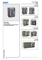
Testing procedure A typical arrangement for measurement of operating timings of circuit breaker is given in Figure 1.
(Figure 1)
2
Make connections as per above figure. Ensure that R, Y and B phase marking cables are connected with proper terminal with the CB (Circuit Breaker) analyzer and maintained color Coates for all the three poles of CB. Connection is to be made for measuring the operating timings of auxiliary contacts AC/DC supply to be extended to CB analyzer Give closing command to closing coil of CB and note down the PIR and main contact closing time. Obtain a print from a CB analyzer Give tripping command to trip coil 1 of CB and note down the main contact tripping time. Repeat the same for tripping coil 2 Note the down the timings of various operations of CB viz. CO, OC, OCO by giving appropriate command. In the event of PIR opening time is required the same may be isolated from the main break and treated as a separate contact using different channel of the analyzer. EQUIPMENT RECOMMANDED: HISAC 2406 CB ANALYZER [Make: Scope] SCOT TIME INTERVAL METERS
Evolution of test results The permissible pole discrepancy as per IEC 56 between 2 poles should not be beyond 1/6 of cycle (3.33 ms) and between 2 breaks should not exceed 1/8 th of a cycle (2.5 ms). As per the practice followed by the most power utilities the limit for pole discrepancy between pole to pole is of the order of 5 ms for breakers under O&M as it is difficult to make any adjustments at site. If these timings are not within limits it may lead to over-stressing of one particular interrupting chamber. Switching over voltage may also be high in case of larger discrepancies in closing timings of the pole because of presence of trapped charges in the phase of circuit breakers which is going to close last. Variation in the operating timing of the order of 3 ms from the base values is generally considered acceptable. However, if these are not within the limits the same is to be corrected by: Equalizing the SF6 pressure in different poles
3
Make necessary adjustment plunger of trip of close coil Adjustment in operating mechanism Changing trip / close coil if required It is also necessary to measure the timings of auxiliary contacts from the point of view of variations with respect to main contact. If the difference in timings of the main or auxiliary contact is maintained within limits this reveals that there is no problem with the auxiliary contact assembly or with the operating mechanisms or with the operating levers of the CB.
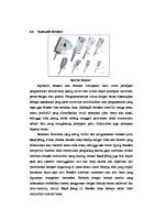
Contact resistance measurement Purpose of measuring contact resistance measurement is to assess the condition of the main contacts against erosion or misalignment of the main contacts. The value of the contact resistance for a new circuit breaker should be around 50 micro-ohms per break. Testing procedure A typical arrangement of measuring the contact resistance is given in Figure 2 below.
Figure 2 The Contact Resistance meter(CRM100) is employed for measurement of pumping resistance. To measure the value, connect the leads as per above figure and inject approximately 100-ampere current flow through the contacts. The value of the contact resistance is directly displayed on the digital LED display screen. By using the
4
Kelvin’s 4 terminal method, effects of resistance of test lead is nullified because the input impedance of the measuring device is very high. If the value of the contact resistance exceeds the permissible limits, this could lead to over heating of contacts. Monitoring contact resistance values is very good techniques for assessing the condition of main contacts. Resistance values of the order of the 100-125 micro-ohms per breaker are considered to be all right for the CB in service.
EQUIPMENT RECOMMANDED: CRM100B, CRM100C [Make: Scope]
DCRM….Definition Dynamic Contact Resistance Measurement is a signature of change in contact resistance of CB during operation. It plots the variation in contact resistance while first, the arcing, and then the main contacts engage and disengage during C-O operation.
Why DCRM…
• • •
Reflects useful information on Contact condition Gives prior indication of deterioration
Operating mechanism linkages
Certain mechanical weaknesses, undetected by travel measurement, are reflected in DCRM measurement.
5
A Look at Contact Assembly Incom Flange
Out Flange
Main Contact, Moving
Moving contact Holder
Arcing Contact, Moving
Arcing contact, Fixed
Main Contact, Fixed Fixed contact Holder
6
Motion…
Fixed contact
A Look at CB
•
Moving contact
The Energy stored in medium is rapidly delivered for moving the CB contacts in a pre-determined fashion, through linkages.
Linkage
DCRM
Operating Rod
Latch
Any change in the dynamic/frictional characteristics of the whole system, immediately reflects as a change in the dynamic resistance signature N
•
R E A C T I O
Mechanism
Stored Energy
Dynamic Resistance Measurement…
7
CB in Motion..!!
Voltage Pickups Current Injection
Dynamic Resistance
Oscilloscope
meter
A C
T
E V E N
Main and Break … Contact
CB Contacts during Make
Break
Contact Make Resistance
8
Time-
A Look at Practical resistance values
…
Our Observations in last 5 years
• • •
Main contacts: 40 to 80 micro-ohms Arcing contacts: 125 to 600 micro-ohms Flange to flange joints: 100 to 1000 micro-ohms
9
Moving Contact
Fixed Contact
10
Arcing Contact 10 Years Before………
11
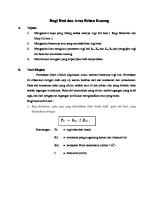
Dynamic contact resistance measurement A typical arrangement for measurement of dynamic contact resistance of CB is given in Figure 3.
(Figure 3 ) This another technique for measuring the contact resistance during dynamic conditions i.e. during operations (close/trip) of CB. A DC current is injected through the CB and the current and voltage drop are measured and the resistance is calculated. The graphs of resistance vs. time data provide useful information on the condition of the main contact of CB and is considered to be a modern diagnostic tool. The variation in the measure resistance vs. time will be seen as ‘finger print’ for the breaker contacts and can be used as reference / base value for comparing future measurement on the same breaker. If the DCRM values matches with the precommissioning /base value then the arcing contact are considered to be O.K. In case of wide variation and also there is change in arcing contact insertion time this shows
12
erosion of arcing contacts. Such as situation may lead of transferring of current from arcing contacts to main contacts and subsequent commutation failure. EQUIPMENT RECOMMANDED: DCRM100B, 200B [Make: Scope]
Contact Travel Measurement Transducers and fixtures are attached to operating rod or interrupting chamber for measuring contact travel. When CB closes contact travel is recorded. Contact bouncing and any other abnormality is also pointed out by contact travel measurement. If contact travel is recorded with DCRM the length of the arcing contact shall also be monitored. It is generally observed that after some time due to erosion of arcing contact the tip length reduces and such condition may lead of commutation failure. This may lead to shifting to arc to main contacts and results in faster damage of main contacts. If contact travel, contact speed and contact restoration signature are compared with the original signature it shall reveal problems related with the operating mechanism, operating levers, main / arcing contacts, contact alignments etc.
Tan Delta and Capacitor Measurement of Grading Capacitor 13
The purpose of this measurement is to be detected any incipient weakness in the HV insulation. The grading capacitor play a vital role when circuit breaker trips TRV stress conditions and also in open condition of circuit breakers. Electrical and thermal stresses produced during operation of CB do lead to degradation of paper insulation of capacitor, capacitor elements and also to the oil in grading capacitors. The value of the tan delta or loss angle increases with degradation of paper or oil. A typical arrangement of tan delta measurement is given below in Figure 4.
Figure 4 Testing procedure Connect LV cable to the middle of the double interrupter Connect HV cable to the other end of grading capacitor to be tested Ground the opposite end of the grading capacitor using earth switch Measurement to be done in UST mode Follow the procedure provided by the equipment supplier. Measurement to be made at 2 kV first and then at 10 kV. Carry out the measurement in the standard mode and also the high quality mode Interpretation of test results A large number of failures of electrical equipment have been reported due to deteriorated condition of the insulation. The correct interpretation of test results requires knowledge about the equipment construction and characteristics of particular type of insulation.
14
Dissipation factor measurements indicate the following conditions in the insulation of wide range of electrical equipments: 1. Chemical deterioration due to time and temperature, including certain cases of acute deterioration caused by localized overheating; 2. Contamination by water, carbon deposits, bad oil, dirt and other chemicals; 3. Severe leakage through cracks and over surfaces; 4. Lionization. Dialectic strength of insulation decreases with the increase in the moisture content. At high temperature is pushed out of the paper insulation with oil. As insulation cooled down water starts migrating from oil into paper. The time for temperature drop may be faster as compared to water returning to cellulose material. Depending upon the condition the dissipation factor also changes. An increase in the value of tan delta indicates the deterioration of cellulose insulation whereas increase in both tan delta and capacitance reveals entry of moisture in the insulation. Ambient temperature At 20 degree C the value of tan delta should not be more than 0.007. In the present testing kit available the software is available to give the test results at 20 degree C and also at rated frequency irrespective of the measurement being made at some other temperature. Factors affecting test results/measurements 1. Temperature – The dialectic losses of most insulation increases with temperature. A rising temperature causes a rise in dialectic loss which in turn causes a further rise in temperature. This is general tendency for capacitance to increase with the temperature. Deterioration of insulation due to aging causes exponential rise of tan delta with the increase in temperature and is expressed as follows: Tan T = Tan Where T0 = 20° C T = Temperature of the specimen Tan To = Tan T at temp. T = Temperature coefficient varies between 0.01 and 0.015° C (if the value is between .05 and 0.3 it considered as questionable condition. Value of more than .03 is a sign of alarming condition) 2. Deposit of surface moisture can have significant effect on the surface losses and consequently on the results. With a view to minimizing the errors the
15
dissipation measurements may be made when the weather is clear and sunny and the relative humidity is less than 80%. 3. Surface leakages – Any leakage over the insulation surfaces of the specimen will get added to the losses in the insulation and make a fake impression about the condition of specimen. It is recommended that surfaces of insulation should be cleaned and dry when taking a measurement. 4. Electrostatic interference – In the energized switch yard, readings may get affected by electrostatic interference current resulting from the capacity coupling between energized line and the bus work to the specimen. To overcome this all the jumpers connected need to be opened when taking a measurement. In the modern automatic testing kits the effect of interference gets nullified due to presence of interference suppression circuits. EQUIPMENT RECOMMANDED: FT-12 [Make: Presco AG]
16
Dew-point measurement of SF6 gas/air 6.4.3 Dew point is the temperature at which moisture content in SF 6 gas/air starts condensing. Measurement of dew point of SF6 gas/air is considered to be a adequate parameter for monitoring of SF6 gas/air. Dew-point measurement of SF6 gas in SF6 CB 6.4.4 Measurement of dew point of SF6 gas in a circuit breaker reveals the change in the value of dielectric properties of SF6 gas. Dielectric properties of SF6 dew get changed with time due to mixing of impurities like moisture, decomposition products of SF6 gas viz. hydroflouride lower valence sulphur fluorides etc. The ingress of moisture in SF6 gas after filling in CB and during O&M could be due to: Exudation of moistures contained during manufacturing from insulation materials used in circuit breakers. Permeation of moisture through sealed sections viz. gaskets ‘O’ rings etc. In the event of presence of moisture in SF6 it gets hydrated to produce highly reactive H2SO3 and HF (hydrogen fluorides). These chemicals results in degradation of insulation and corrosion in the interrupting chamber. As such monitoring of moisture content in SF6 is considered to be very important. Chemical reactions taking place during moisture control conditions are given below: (a) When moisture density is low
SF4 + H2O .................
SOF2 + 2 HF
SOF2 + H2O ................
SO2 + 2 HF
(b) When Moisture density is high
SF4 + 3H2O ................
H2SO3 + 4 HF
2SF2 + 3H2O ...............
H2SO3 + 4 HF
Sulphur oxifulorides, hydrogen fluorides and H2SO3 formed during these reactions attack the materials containing silicon-dioxide (SIO2) viz. glass / porcelain. Primary and secondary decomposition in the presence of moisture forms corrosive electrolytes which may cause damage and operation failure. Testing procedure A typical arrangement for dew point measurement is given below in Figure 5.
17
(Figure 5) Make the connection to the kit from circuit breaker ensuring that regulating valve is fully closed at the time of connection of the dew point kit. Regulate the flow rate of SF6 (0.2-0.5 L/minute) as per IEC 480, the value of the dew point is observed till it becomes stable. Note.: If the regulating valve is provided at the outlet of the dew point kit then dew point value for rated pressure are to be monitored. Frequency of Dew Point Measurement The discharge of moisture from the organic insulating material is faster initially and the rate of release becomes almost negligible after 4 to 5 year of commissioning, and thereafter moisture entry in the CB is through permeation. Recommended frequency of dew point measurement is as given below: First time at the time of commissioning After six months After one year thereafter Once in two years EQUIPMENT RECOMMANDED: SHAW MOISTURE METER Monitoring of Dew Point Values Dew point of SF6 gas varies with the pressure due to the fact that saturation vapor pressure decreases with increase of SF6 pressure. Dew point of SF6 at higher pressure is lower than the dew point at atmospheric pressure. Table given below give
18
the value of dew point at rated pressure and at atmospheric pressure for various makes of CBs.
Sl.No. Make of CB Dew point at rated pressure (Min. º C)
1.
2
3
4
5
BHEL
Dew point at Remarks Atmospheric Pressure (limit) (Min º C)
-15
- 36
At the time of commissioning
-7
- 29
During O&M
-5
- 27
Critical
--
- 39
At the time of commissioning
--
- 32
During O&M
- 15
- 35
At the time of commissioning
- 10
- 31
During O&M
- 15
- 35
At the time of commissioning
-5
- 26
During O&M
-15
-36
At the time of commissioning
-7
- 29
During O&M
-5
- 27
Critical
M&BG
CGL
ABB
NGEF
Dew Point Measurement of Air in ABCB The dialectic properties / arc quenching properties of dry air do get change with the aging of CB and quality of air deterioration if moist air travel to the interrupting chamber. This will lead to deterioration of internal insulation and resulting in unsuccessful arc quenching. It is therefore necessary to carryout measurement of
19
dew point of air in ABCBs. The permissible limits of due point of ABCB is given in Section 7. Other Condition Based Maintenance Techniques Besides the above mentioned condition based techniques, the other techniques adopted includes – monitoring of trip / close coil current, coil current measurement, SF6 gas/air leakage test rate and operating mechanism medium oil/air pressure. Friction in the plunger movement gap between the plunger and the pin of the coil assembly are reflected in the recorded current values / wave shapes. Leakage rate of SF6 gas indicates healthiness of the ceiling system, O ring and strength of cementing joints. SF6 gas leakage upto 1% per annum is considered to be within acceptable limits. Operation Lockout Checks for CB Following operation lockout checks are carried out: a) SF6 gas pressure lockout: Low pressure alarm Operation lockout alarm b) Pneumatic operating system lock-out Compressor star / stop switch CB auto reclose lock-out switch CB closing lockout CB operation lockout Mechanical closing interlock (applicable for air blasé CBs) c) Hydraulic operating system lockout Pump start/stop CB auto re-close lockout CB closing lockout CB operation lockout Evaluation of Test Results
20
a )SF6 gas pressure lockout: All the SF6 gas pressure switches settings should be checked and corrected with ambient temperature. Settings of SF6 gas pressure switches should be within + 0.1 bar/Kg/cm2 of the set value (after taking into account the temperature correction factor). b) Air pressure lockout: All the air pressure switches settings should be checked and corrected and should be within + 0.1 bar/Kg/cm2 of the set value. c) Oil pressure lockout: All the oil pressure switches settings should be checked and corrected and should be within + 0.1 bar/Kg/cm2 of the set value.
TESTING
GO TO TRANSFORMER
CIRCUIT BREAKER TRANSFORMERS CT/CVT’S ARRESTERS
SURGE
21