![CLG230 Bulldozer [PDF]](https://pdfs.asia/img/200x200/clg230-bulldozer.jpg)
10 0 4 MB
Important Safety Information Most accidents involving product operation, maintenance and repair are caused by failure to observe safety rules or precautions. An accident can often be avoided by recognizing potentially hazardous situations before an accident occurs. A person must be alert to potential hazards. This person should also have the necessary training, skills and tools to perform these functions properly. Improper operation, lubrication, maintenance or repair on this product can be dangerous and could result in injury or death. Do not operate or perform any lubrication, maintenance or repair on this product, until you have read and understood the operation, lubrication, maintain and repair information. Safety precautions and warnings are provided in this manual and on the product. If these hazard warnings are not heeded, bodily injury or death could occur to you or other persons. The hazards are identified by the "Safety Alert Symbol" and followed by a "Signal Word" such as "WARNING" as shown following.
The meaning of this safety alert symbol is as follows: Attention. Be alert. Your safety is involved. The message that appears under the warning, explaining the hazard, can be either written or pictorially presented. Operations that may cause product damage are identified by NOTICE labels on the product and in this publication. LiuGong cannot anticipate every possible circumstance that might involve a potential hazard. The warnings in this publication and on the product are therefore not all inclusive. If a tool, procedure, work method or operating technique not specifically recommended by LiuGong is used, you must satisfy yourself that it is safe for you and others. You should also ensure that the product will not be damaged or made unsafe by the operation, lubrication, maintenance or require procedures you choose. The information, specification, and illustrations in this publication are on the basis of information available at the time when it was written. The specification, torques, pressures, measurements, adjustments, illustrations, and other items can change at any time. These changes can affect the service given to the product. Obtain the complete and most current information before starting any job. LiuGong has the most current information available. CALIFORNIA PROPOSITION 65 Diesel engine exhaust and some of its constituents are known to the state of California to cause cancer, birth defects and other reproductive harm. Battery post, terminal and related accessories contain lead and lead compounds, Always wash hands after handling.
1
CONTENTS Preface
Maintenance Manual
Presentation ...................................................... 3
Run-in ............................................................. 50
General Hazard Information.............................. 5
Maintenance Interval Schedule ...................... 50
Crushing and Cutting Prevention ...................... 8
General Torque Specifications ....................... 64
Burn Prevention ................................................ 9
Important Maintenance Procedures ............... 65
Fire & Explosion Prevention............................ 10
Precautions for Assembly and Disassembly .. 65
Fire Extinguishers and First-aid Kit ................. 11
Bulldozer Structure and Principle ................... 67
Electrical Storm Injury Prevention ................... 11
Recommended Fuel, Coolant and Lubricant 108
Attachment Cautions....................................... 12
INDEX Cautions about Machine Operation ................ 12 Cautions about Machine Maintenance............ 17
Application and Specification Main Specifications ......................................... 20
Operation Manual Before Operation............................................. 22 Operator Controls and Instrument Panels ...... 22 Other Controls................................................. 26 Others ............................................................. 29 Engine Starting ............................................... 32 Operation Techniques..................................... 36 Machine Operation.......................................... 42 Lubrication Chart............................................. 48
2
1 Preface
Preface This manual includes important instructions concerning operation, lubrication, checking testing, adjusting the machine and permanent key components. This manual should always be kept safe, clean and with the machine where it is convenient to find for operators to use. This manual should not be separated from the machine even when reselling or leasing. Some photographs and illustrations in this manual show details of attachments that may be different from your machine. Guards and covers may have been removed for the purpose of illustration. Read this manual carefully and follow all instructions for proper operation and maintainance of this machine. Instructions in this manual should help the reader avoid possible personal injury or damage to the machine. The operator should proficiently and correctly operate the machine to ensure safety. Use this machine only for the purpose described in this manual. Contact your LiuGong dealer for approval before making any modifications or adding attachments to the machine. The addition of any unauthorized attachment may cause operation of the machine to become unsafe and reduce the service life of the machine. Guangxi LiuGong accepts no liability for any damage resulting from the use of unapproved attachments or working practices. Only trained or experienced personnel should be allowed to operate or maintain this machine. Correctly record the machine type, serial number, engine serial number and all major component serial numbers for your reference when ordering parts or in the event of theft. Record the correct numbers to both the operators manual and a secure place outside the machine.
Safety The safety section lists basic safety precautions. In addition this section identifies the text and locations of warning signs and labels used on the machine. Read and understand the basic precautions listed in the safety section before operating or performing lubrication, maintenance or repairs on this machine. Operation The operation section is a reference for the new operator and a refresher for the experienced operator. Read, understand and reference it when ever neccessary. This section includes a description of gauges, machine controls, switches and other controls at the operators staion. It also provides transportation and towing information. Photographs and illustrations guide the operator through correct procedures of checking, starting, operating and stopping the machine. Operating techniques outlined in this publication are basic. Skill and techniques develop as the operator gains knowledge of the machine and its capabilities. Maintenance The maintenance section is a guide for equipment care. The illustrated, step-by-step instructions are grouped by servicing intervals. Items without specific intervals are listed under the "When Required" service interval. Items in the "Maintenance Intervals" are referenced to detailed instructions that follow.
2 Preface
Maintenance Intervals Use the service hour meter to determine servicing intervals. Calendar intervals shown (daily, weekly, monthly, etc) can be used instead of service hour meter intervals if they provide more convenient servicing schedules and approximate the indicated service hour meter reading. Recommended service should always be performed at the interval that occurs first. Under extremely severe, dusty or wet operating conditions, more frequent lubrication than is specified in the "Maintenance Intervals" may be necessary. Perform service on items at multiples of the original requirement. For example, at every 500 service hours, also service those items listed under every 250 service hours, 50 service hours and every 8 service hours or daily. All the information, figures, tables and specifications are the latest product information obtainable at the time of publication. Guangxi LiuGong Company will reserve the right to make change without notice. Certified Engine Maintenance Correct maintenance and repair methods are essential to keeping the engine and machine systems operating correctly. As the owner, you are responsible for performance of required maintenace listed in the Maintenance Manual for this machine. It is prohibited for person engaged in the business of repairing, serviceing, selling, leasing or trading engines or machines to remove, alter or render inoperative any emmissions related device or element of design installed on or in an engine or machine that is in compliance with the regulations. Certain elements of the machine such as exhaust system, fuel system, electrical system, air intake system and cooling system may be emmision related and should not be altered unless approved by LiuGong.
3 Preface Presentation
Presentation
4 Preface Presentation
Type and Serial Number of the Machine and Parts Manufacturer Name
Guangxi Liugong Machinery Co., Ltd.
Type of the Machine Serial Number of the Machine Type of Engine Serial Number of Engine Type of Transmission Serial Number of Transmission Type of Hydraulic Pump Serial Number of Hydraulic Pump Cab Manufacturer Serial Number of Cab
Note: The user should fill out the above table according to the specific configuration of the machine after receive the machine.
5 Preface General Hazard Information
General Hazard Information Be familiar with all safety cautions, failure to observe could result in property damage, serious injury or even death. Only trained and qualified personnel should be allowed to operate or maintain the machine.
Wear relevant personal protective equipment (PPE) such as a hard hat, ear protection, safety glasses, safety shoes and gloves when operating or servicing the machine.
Do not operate the machine if you feel sick, sleepy or after taking some medication. Check with your doctor if unsure. Never operate machinery while under the influence of drugs or alchohol.
Da te :
O
pe
ra
te r:
!
d op o n er ot at e
W
AR
NI N
G
Attach a DO NOT OPERATE or similar warning tag to start switch or control levers before servicing or repairing the machine.
Do not wear loose fitting clothing, dangling jewelry or long hair that can catch on controls or in other moving parts of the machine.
Using goggles, safety glasses or full face mask can protect your eyes from being injured by high pressure liquids, when maintaining storage batteries, by flying scraps when the engine is in operation or you are using tools to strike objects, remove springs or resilient parts, add acid/ electrolyte to batteries, you should wear a full face protective mask. When carrying out welding operations or gas cutting operations with a welding torch, wear specific safety goggles suitable for the task being performed. Consult your welding equipment dealer for more information.
6 Preface General Hazard Information
Pay attention when opening fluid compartments, prevent foreign materials from entering the system. Always remove loose materials from near caps and plugs.
When working under high noise conditions, wear appropriate safety equipment to protect your hearing, such as approved earmuffs or plugs. Avoid the damage caused by exposure to high noise on your hearing.
Know the appropriate worksite hand signals and who gives them. Accept signals from one person only. Never put maintenance fluids into glass containers. Observe the relevant laws and regulations when handling harmful articles such as lubricants, fuels, coolants, solvents, filters, batteries and other matterials. Use all cleaning solutions with care. Do not use any flammable material to wash components, for example, diesel oil or gasoline. They may easily catch fire.
Make sure all protective guards and covers are secured in place on the machine. Always replace protective guards and covers removed for servicing or maintenance. Repair damaged guards and covers before operation. Keep the machine, especially the panels, accesses, step and ladders, free of foreign material, such as debris, oil, tools and other items which are not part of the machine. Secure all loose items such as lunch boxes, tools and others. Report all required repairs in time. Do not allow unauthorized personnel on or around the machine. Guangxi Liugong bear no resposibility for failures caused by modifications to machine structure without Liugong’ s permission.
7 Preface General Hazard Information
Compressed Air Compressed air can cause personal injury. When using compressed air for cleaning, wear a protective face shield, protective clothing, hearing protection and protective shoes. Never direct compressed air at yourself or others. Compressed air could penetrate your skin and cause serious injury or death. The maximum air pressure used should not exceed 25psi(0.2Mpa).
Even a pin-hole size leak can cause serious injury, If you are hit by spraying high-pressure oil, see a doctor for treatment at once.
High-pressure Fluid WARNING: Avoid injury from highpressure oil. When repairing hydraulic lines, ensure that system pressure is completely released before beginning the repair. Hydraulic oil under pressure contacting the skin could cause serious injury or damage. Use cautiion before disconnecting hydraulic lines or connectors. High pressure oil that is released can cause a hose to whip. Always support attachments and release residual pressure before attempting to disconnect hydraulic lines. Pressure applied by loads on attachments could cause hydraulic oil to spray when lines are removed. Wear safety glasses and leather gloves. Never check for a high-pressure leaks with your unprotected hand. Use a board or cardboard when checking for leaks.
Disposal of Waste Fluids Improper handling of the waste fluid will cause pollution of the environment. Obey all local regulations for disposal of waste fluids. Collect all waste fluids when performing inspections, maintenance, testing, adjusting and repairs to the machine. Prepare to collect fluids with suitable containers before opening any compartment or disassembling any component that contains fluids. Use suitable containers to collect waste fluids. Do not use food containers or beverage bottles as they could mislead people to drink the contents.
Cautions about Accumulators High-pressure nitrogen is contained in the accumulators making them dangerous articles. Read the following requirements and pay attention to the proper use of accumulators.
8 Preface Crushing and Cutting Prevention
Check accumulators before charging with nitrogen. Safe use cannot be guaranteed if there is not a nameplate attached to the accumulator. Never charge accumulators that have an incomplete nameplate or that are of an unidentified type.
Shower after contact with asbestos. Wear an approved respirator if there is no other way to control the dust. .
Accumulators are charged with nitrogen. The use of oxygen, compressed air or other flammable air in the accumulator could cause an explosion and possible injury, death and damage to the machine. When charging accumulators with nitrogen, care should be taken not to damage the diaphragm. The accumulator's valve should be installed facing vertically upward. Do not attempt to fix accumulators by welding them. Do not drill any hole in the accumulator or close a hole by welding. Do not weld a boss on the accumulator. Accumulators are high-pressure vessels and should be repaired only by trained specialized personnel. Always release pressure in the accumulator before disposing of it. Asbestos Danger Breathing asbestos dust can be hazardous to your health. Equipment and replacement parts shipped from Liugong have no asbestos in them. Liugong recommends the use of genuine factory spare parts only. Observe the following rules if you are handling any spare parts that contain asbestos or asbestos fibers: Never use compressed air to clean up asbestos. Use a wet method in order to clean up asbestos materials. Water the area down to clear asbestos dust. A vacuum cleaner that is equipped with a high efficiency particulate air filter (HEPA) can also be used. Do not grind materials that contain asbestos. Obey environmental regulations for the disposal of asbestos.
Crushing and Cutting Prevention Don't put hands, arms, or any other parts of the body in the way of removable parts. Support equipment and attachments properly when working beneath them. Do not depend on hydraulic cylinders to hold up the implement/ attachment. The implement/attachment can fall if a control lever is accidentally moved, or if a hydraulic line breaks. If it is necessary to remove shields in order to perform maintenance, always install the shields after the maintenance is performed. Check all protective devices for safety such as doors, safety guards and covers. Ensure they have been installed correctly so as to avoid any possible injury caused by moving parts, for example: prevent fans from causing injury by cutting. Keep clear or stop engine before servicing. If any door, guard or cover are damaged, they should be repaired or replaced before using the machine.
9 Preface Burn Prevention
Keep hands and objects away from moving fan blades. They can throw or cut any object that contacts the moving blades.
Check the coolant level only after the engine has been stopped and the coolant filler cap is cool enough to remove with your bare hand.
Never attempt adjustments while the machine is moving or the engine is running unless otherwise specified.
Remove the cooling system filler cap slowly to relieve pressure.
If the machine must be repaired with engine running, make sure that a qualified operator is available in the cab to shut down the engine if required. Do not use a kinked or frayed wire cable. Wear gloves when handling wire cables. Retainer pins, when struck with force, can fly out and injure nearby persons. Make sure the area is clear of people when driving retainer pins. Wear protective glasses when striking a retainer pin to avoid injury to your eyes.
Coolant contains alkali that can cause personal injury. Avoid contact with the skin, eyes and mouth. Oil Hot oil and components can cause personal injury. Do not allow hot oil or components to contact the skin.
Chips or other debris can fly off objects when struck. Make sure no one can be injured by flying debris before striking any object.
Burn Prevention
At operating temperature the hydraulic oil tank is hot and can be under pressure.
Some parts of the machine become hot during normal operation. Use caution when maintaining the engine and hydraulics. Allow the machine to cool after it has been operating for a long period of time.
Remove the hydraulic oil tank cap only after the engine has been stopped and the cap is cool enough to remove with your bare hand.
Coolant
Relieve all residual pressure in air, oil, fuel or cooling systems before any lines, connectors or related items are disconnected or removed.
At operating temperature, the engine coolant is hot and under pressure. The radiator and all lines to heaters and the engine contain hot water or steam. Any contact can cause severe burns.
Remove the hydraulic oil tank oil filling cap slowly to relieve pressure.
Batteries Batteries give off flammable fumes which can explode. Batteries and battery terminals may contain lead, do not touch batteries with your bare hands. Always wash your hands right after maintaining a battery. Do not smoke when observing the battery electrolyte levels.
10 Preface Fire & Explosion Prevention
Electrolyte is an acid and causes personal injury if it contacts skin or eyes. If contact occurs flush with water and seek medical attention right away. Always wear protective glasses and gloves when checking batteries.
Store all oily rags or other flammable materials in a protective container away from naked flames or other sources of ignition. Do not weld or flame cut pipes that contain flammable fluids. Remove them from the machine and clean them thoroughly with nonflammable solvent before welding or flame cutting on them. Remove all flammable materials such as fuel, lubrication and other debris before they accumulate on the machine. Do not operate the machine near an open flame. Keep all open flames or sparks away from the battery. Do not smoke in battery charging areas. Do not charge a frozen battery. This may cause an explosion.
Fire & Explosion Prevention
Ether
All fuels, most lubrications and some coolant mixtures are flammable.
WARNING: EXPLOSION HAZARD. Do not use ether. Machine is equipped with electrical cold weather start aid device.
Fuel leaked or spilt onto hot surfaces or electrical components can cause a fire. Do not smoke while refueling or in a refueling area, or where flammable materials are stored.
Clean and tighten all electrical connections. Check daily for loose or frayed electrical wires. Have all loose or frayed electrical wires tightened, repaired or replaced before operating the machine.
Starting the machine by use of ether could result in serious damage to the engine or personal injury or death.
Cautions Concerning Lines, Tubes and Hoses
Check the electric circuit periodically to avoid fire caused by overload or short circuit.
Do not bend or strike high-pressure lines. Do not install bent or damaged tubes or hoses.
Keep all fuels and lubrications stored in properly marked containers and away from all unauthorized persons.
Tighten any loose fuel or oil pipes, hydraulic system tubes or hoses. Repair any damaged fuel or oil lines, tubes or hoses. Leaks can cause fires. Contact Liugong or your Liugong Dealer for factory authorized replacement parts.
11 Preface Fire Extinguishers and First-aid Kit
If you see evidence of any of the following situations, replace the part before using:
°§Connectors damaged or leaking. °§Outer covering frayed or cut and reinforcing wire exposed. °§Outer covering ballooning. °§Evidence of kinking or crushing. °§Reinforcing steel wire of the hose embedded in the outer covers. °§Connectors incorrectly fitted or tensioned.
Keep telephone numbers of doctors, first-aid centers or fire stations etc with you so you can contact them in case of an emergency. Post the contact telephone numbers in regulated places. Ensure that all persons know where the telephone numbers are located and know the correct contact method.
Make sure that all clamps, guards and heat shields are properly installed. During operation this will prevent vibration, abrasion, friction with other parts and guard from excessive heat. Before removing or servicing any lines of the air conditioning system, always ensure there is not an open fire nearby, any escaping gas coming into contact with fire could result in poisonous fumes. Never smoke when servicing or repairing the air conditioning system, any escaping gas that burns and inhaled can cause bodily harm or death.
Fire Extinguishers and Firstaid Kit A fire extinguisher that meets with all local fire extinguisher laws and regulations should be available on the machine. Maintain the fire extinguisher in accordance with all local laws and regulations. Contact your local fire department for further information. Know how to use the fire extinguisher and firstaid kit. A first-aid kit should be available at the work site. Periodically check the contents of the kit and replace used medical supplies as necessary.
Inspect and service the fire extinguisher regularly. Obey the recommendations on the instruction plate and all local laws and regulations relating to fire extinguishers.
Electrical Storm Injury Prevention When lightning is striking in the vicinity of the machine, the operator should never attempt to mount and dismount the machine. If you are in the cab during an electrical storm, stay in the cab. If you are on the ground during an electrical storm, stay away from the machine.
12 Preface Attachment Cautions
Operator Station
Mount and dismount the machine only where there are handrails, steps or ladders.
Any modification to the inside of the operator station should not project into the operator space. The addition of radio, fire extinguisher, and other equipment must be installed so that the define operator space maintained. Any item that is brought into the cab should not project into the defined operator space. A lunch box or other loose items must be secured. Objects must not pose an impact hazard in rough terrain or in the event of a tipping.
Face the machine when getting on or off, grab the handrails with both hands and step onto the steps or ladders. Touch three points simultaneously (two feet and one hand or two hands and one foot) to ensure stability of the body.
Attachment Cautions Attachments should only be installed by authorized people who have been trained to operate and maintain the attachment according to the operator’s manual. Refer to the instructions in the operation manual and any other related information when installing and using attachments. Incorrect installation of attachments or optional parts not only will result in safety problems, but also will negatively influence the operation and sevice life of the machine and the attatchments. It is forbidden to modify the machine or any attachments without permission from your Liugong dealer. Liugong bears no responsibility for injuries, accidents or machine damage resulting from the use of unauthorized attachments.
Cautions about Machine Operation Mounting and Dismounting Before mounting or dismounting the machine, check the condition of handrails, ladders and steps. Clean them of grease, lubricants and dirt before use. Repair any damaged parts and tighten loose bolts.
Never jump off the machine. Never get on or off a moving machine. Be careful not to touch any control levers when getting on or off the machine. Do not try to climb on or off the machine when carrying tools or supplies. Use a rope to pull equipment up onto the platform or have an assistant pass them to you. Understand Your Machine Be able to operate all the equipment on your machine. Understand the purpose of all control systems, instruments and indicators. Understand the rated load, speed range, the characteristics of braking and steering, turning radius and the space clearance for operation. Remember that rain, snow, ice, gravel and soft earth may change the performance of the machine. Understand the safety signs on the machine (Danger, Warning, Caution) and any other signs.
13 Preface Cautions about Machine Operation
Understand Your Working Area Before starting, inspect the area where you will be working. You should check: adequate ventilation the position of any slopes, visible ditches, falling or hanging objects, conditions of soils (soft or hard), accumulated water and swamp areas, rocks or stumps, hidden groundwork, posts or the outer limits of walls, the outer limits of the areas where garbage is buried or that are filled in with earth, holes or openings, obstacles, mud or ice, traffic, heavy dust, heavy smoke, heavy fog, the exact locations of cables or pipes for power supply, gas supply, phone service, water supply, sewage disposal and other utilities that are hidden or hung. If necessary before starting work you should ask the utility companies to mark out, close or move out these utilities.
Replace all damaged or lost parts and carry out lubrication according to the maintenance interval schedule. Remove all loose objects from the cab. Loose objects may affect the operation and cause accidents. Make sure that all the windows if fitted are clean and the screenwiper works normally. Adjust the operators seat to a position that is most comfortable and provides for easiest operation of the machine. Check the seat belt and the condition of mounting hardware. Repair or replace any items that are damaged. Replace the seat belt after three years of use or any time the belt shows signs of wear or damage. Check all the illumination equipment before operation in low light, and ensure that the illumination system is in good condition.
Before Starting the Engine Engine Starting Inspect the machine carefully before starting the engine, ensure all systems are in good operational condition. Make sure nobody is on or around the machine before starting the engine.
Do not start the engine if there is a DO NOT OPERATE or similar tag attached to the start switch or control levers.
Keep the steps and handrail clean. Clear any dirt and sands from your shoes before mounting the machine. Check all structural members, covers and fenders for deformation or damaged. Check the condition of safety guards such as doors, guards and covers. Repair any damage as necessary. Check the hydraulic system for oil leakage. Check the condition of hoses and pipes. Check all fasteners for security. Check the condtion of electrical wiring harness and fuses, replace or repair as neccessary. Also check the connectors for good connection. Check the fuel level and fuel system for normal condition, drain any water or sediment in the water/fuel separator. Dispose of fluids in accordance with local regulations.
!
W
AR
NG NI
t no te o d era op r:
te
ra
O
pe
:
D
ate
Do not start the engine until seated in operators seat and the seat belt is firmly fastened.
14 Preface Cautions about Machine Operation
Ensure the hydraulic control levers are all in the NEUTRAL position and the shift control lever is in the NEUTRAL position before starting the engine. Only start the engine from the operators seat in the cab. Never start the engine by short-circuiting the start motor terminals. Starting the engine by short-circuiting could result in damage of the electrical system, personal injury or death. After the engine is started, you should observe, instruments and warning lights, and make sure that they work and every reading is within working range. Observe machine movements and listen carefully for unusual noises. If there is any fault or abnormality, you should stop the engine immediately. Locate the source of the problem and fix before further operation.
Keep all the windows, lightshades and rearview mirrors clean. Secure doors and windows in either the open or shut position. Adjust the rearview mirrors for best vision, especially close to the machine. Clear all obstacles from where the machine will be working. Be aware of hazards such as high voltage wires, ditches, etc. Make sure the horn, backup alarm (if equipped) and all other alert devices are working properly. Machine Operation Before run the machine on roads, check that whether the machine meets the requirements of the local laws and regulations for roads traveling and make sure that you get the road traveling permission from relevant road administration offices. Observe the local traffic regulations when driving the machine on roads. Before driving the machine, you should carefully observe the surroundings, and find out the relations between the direction that you want to go in and the pedal/operating lever.
Never run the engine in a closed or poorly ventilated environment. If working inside a building, open the doors and windows to ensure enough ventilation and try to prevent exhaust gas poisoning. Use a power exhaust system when working in an enclosed area.
Do not allow another person seating on the machine unless equpped with additional seat, seat belt and Rollover Protective Structure (ROPS).
Before operating the machine, you should operate the machine slowly to an open area, check for proper operation of all control levers and all protective devices. Before Operating the Machine Make sure the machine is free of personnel and fasten the seat belt before operation.
Note any needed repairs during machine operation such as an abnormal noise, vibration, smell, wrong reading of gauges, gas or oil leakage, etc., stop what you are doing and report any needed repairs in time.
15 Preface Cautions about Machine Operation
Dust, heavy rain, and heavy fog will blur your vision. You should keep windows, mirrors and lights clean and in good conditions. When the visibility decreases, you should decrease the speed and apply the proper lights.
Avoid operating the machine across the slope. When possible, operate the machine up the slopes and down the slopes.
If driving or operating the machine with a bad view or in a crowded area, you should work with a signalman, keep the signalman within the field of your vision, and coordinate your hand signal. Raise the blade to 400~500 mm off ground when traveling.
400-500
If the machine begins to sideslip on a slope, immediately remove the load and turn the machine downhill.
Do not go close to the edge of a cliff, a dyke, or a hillock to avoid collapse.
Be careful when working beside the high voltage wire. If it is possible to contact the ground cable in working, consult the Electricity Company before working. Any contact with the cable will result in serious injuries or death. Keep any parts of the machine away from the cable. Know the accurate height of wire, machine and the ground. If possible, cut off the power before working. If not, use a hand signalman instead. If the machine has contacted the high voltage wire: (a) Alert any person keep away from the machine. (b) If you can handle the contact point, separate the high voltage wire with the machine and make it leave safely. (c) If you can not handle the contact point, stay inside the cab until the Electricity Company cut off the wire and you are informed to go out.
Avoid any conditions that can lead to the machine tipping. The machine can tip when you work on hills, on banks and on slopes. Also, the machine can tip when the machine goes cross ditches, hillocks or other unexpected obstructions.
(d) If a fire occurs, fold your feet as possible as you can and jump off the machine with hands untouched the ground. Try to jump into a safe place. When transporting, make sure that the hooks and the towing devices are adequate. Connect trailing equipment to a drawbar or hook only. Never straddle a wire rope cable or similar device, nor allow others to do so.
16 Preface Cautions about Machine Operation
No personal should be between the machine and trailing equipment when maneuvering to connect them. Block the tongue or hook of trailing equipment to align it with the drawbar or hook.
Stop the engine, and take out the key from the switch.
Parking the Machine
When leaving the machine lock all equipment covers and doors with the key. Remove the key and keep it with you.
When possible choose flat level ground to park the machine, apply the parking brake (if equipped), always lower any attachment to the ground and ensure the machine will not move, possibly causing damage or injury.
Turn the battery disconnect switch to OFF position to avoid battery discharge.
Consider any overhead hazards such as the posibility of falling rocks, any powerlines or any other overhead hazards that may exist. Consider the ground conditions. Do not park the machine near the edge of a cliff, close to an open excavation or pit. Consider environmental conditions such as the posibility of flooding, heavy snow fall, electrical storms and exposure to wind and cold. Any of these conditions may cause damage to the machine. Do not cause an obstruction, consider the site access and other emergency conditions the machine may obstruct. If it is necessary to park the machine on a slope or incline, lower the implement to the ground, engage the parking brake and shut off the engine. Place chocks under the wheels at the downhill side on both sides to prevent the machine from moving. Understand and obey all regulations relating to public roads, if the machine is parked on a public road. Additional signage or lighting may be required. Always lower attachments or other equipment before leaving the machine, apply the parking brake (if equipped). Put the hydraulic control levers to NEUTRAL position and the shift control lever to NEUTRAL position. Engage the parking brake (if equiped). Keep the engine running at idle speed for five minutes to let the engine cool down gradually.
Lowering the Attachment/ Implement with Engine Stopped CAUTION: For a machine controlled by electro-hydraulically control lever, in order to lower the implement, the engine start switch must be on ON position .Turn the engine start switch to OFF position after lowering the implement. In order to lower the implement to the ground or trailer, move all control levers to DOWN position. When release them, they will return to HOLD position.
17 Preface Cautions about Machine Maintenance
Store Accessories Safely
Transportation Information
Store accessories and tools safely so as to prevent them from falling and causing serious injury or death. Keep playful children and bystanders away from the storage area or any area accessories are being stored whilst in use.
Obey the appropriate laws that govern the parameters of the load (weight, length, width, and height). Understand the correct procedures for loading and unloading. Carry out the loading and unloading operations on flat ground. Chock the wheel of the trailer to make it unable to move.
5
Cautions about Machine Maintenance Prepare the Working Area Please choose a clean and flat area with adequate space, enough light, and good ventilation to carry out any repair work. Clean the ground surface, wipe up fuel, lubricating oil and water, and spread sands or other absorptive materials on the slippery ground. Keep the work area clean and dry. Support the Machine Correctly Lower to the ground or support any attachments with stands or other methods. Ensure that any attachment can not move during maintenance or repair work, use wheel chocks or other devices to prevent machine movement. Do not work under any part of the machine or attachment that is not adequately supported. Do not rely on hydraulic systems as support. Use stands or other measures that are secure and can support the weight being applied to them.
1
4 3
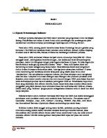
1. 2. 3. 4. 5.
2
Wedge Block Angle (Max. angle is 15°) Distance between the ramps Ramp
Use loading ramps appropriate for the machine being moved. Consider: size, strength, departure angle and proper height. Make sure that the loading ramp is anti-slip and free of mud and snow. Use chains and blocks to secure the machine to the trailer. Keep the bystanders away. Place all the working equipment in the transportation position, secure all the equipment and attachments or additional equipment with chains or other secure methods to prevent accidental movement.
18 Preface Cautions about Machine Maintenance
Welding Operation Any personnel engaging in welding operations must have occupational certificates and carry out the operation at a place with appropriate devices equipped, When carrying out the welding operation, the personnel must follow the instructions below:
When carrying out the cleaning operation, wear suitable PPE. Consider exposure to: chemicals, slippery surfaces, high pressure water spray and material splash.
Before carrying out the welding operation, turn off the battery isolator switch, disconnect the battery, disconnect the controllers, GPS and other electrical parts. Remove all paint from the place to be welded, so as to prevent harmful gas from being produced. Do not inhale smoke produced buy burning paint. Never weld pipes, close to rubber hose and electrical wires. Always remove residual pressure from the machine. Never weld pipes that are fitted to the machine. Always wear correct PPE for welding, protect bystanders by using screens and signs advising of the operation being performed. Ensure good ventilation. Remove all the inflammable materials, supply the work area with a fire extinguisher.
Clean the Equipment Periodically To avoid possible injury or damage to the machine, all the oil and scraps accumulated should be removed. The engine, radiator, storage battery, hydraulic hose, fuel tank and cab should be kept clean.
Do not spray the water directly onto sensors, connectors or instruments of the electrical system. If water enters the electrical system malfunction may occur.
19 Application and Specification Cautions about Machine Maintenance
Application and Specification Applications This bulldozer is a kind of earth-moving construction machinery. It is mainly used for roading, building,mine areas, water, agriculture, forestry and other construction building work. It is mainly applicated for shoveling, bulldozing, levelling, scarifying and snow ploughing and so on. Requirements of Work Environments (1) Altitude: ≤ 3000m (2) Environmental temperature: -20°C~40°C (The cold starting aid device is not available) (3) Water Depth: ≤ 530mm CAUTION: Preventive measures for operation, maintenance and safety rules outlined on this manual are only suitable for the stipulated applications of the machine. Do not use the machine beyond the stipulated application scope, Guangxi Liugong Machinery Co., Ltd will not bear any safety liability, and these safety liabilities will be born by users. Under any cases, do not use the forbidden operation outlined in this manual.
20 Application and Specification Main Specifications
Main Specifications Machine Specifications CLGB230
CLGB230E
CLGB230D
CLGB230S
CLGB230R
Notes
24160
24910
25240
26710
27340
Include straight dozer, cab. Exclude ripper
11.8
11.8
11.8
10.7
10.7
14.3
14.3
14.3
13.3
13.3
Model Spec. Weight (kg) Forward Max. (F) Traveling Reverse Speed (R) (km/h) Engine Model
CUMMINS NT855-C280
Rated Power
169KW/2000rpm
Max.Torque
1036N.M/1400rpm
Power Train System Torque Converter
Three-member Single Turbine
Transmission
Planetary gear, Multi-disc clutch, Manual lubrication type.
Central Transmission
Spiral Bevel Gear, single reduction,Splash Lubrication
Steering Clutch
Wet, multiple spring compression, hydraulic seperation, hand operated.
Steering Brake
Wet, floating, direct clutching, hydraulic boosted, interconnect operation.
Final Drive
Spur gear, double reduction, splash lubrication
Travel System Type
Oscillation type, equalizer bar suspension
Number of Carrier Rollers
2 Each
Number of Track Rollers
CLGB230 7/Each side (single: 5, double: 2)
Track Type
CLGB230 assembled type, single grouser (39Each)
Track Shoe Width Pitch
CLGB230、 CLGB230E
560mm
216mm
Ripper(Three teeth) Type
Adjustable Parallelogram
21 Application and Specification Main Specifications
Ripper(Three teeth) Tooth number
1~3 tooth
Tooth space
1000mm(3 teeth)
2000mm(2 teeth)
Maximum digging depth
665mm
Maximum lift height
555mm
Weight
2900kg
Dozer Equippment CLGB230、 CLGB230E
CLGB230S
CLGB230R
CLGB230D
Model Spec.
Straight blade
Angle blade
U blade
Straight blade
Blade width
(mm)
3725
4365
3860
4365
4365
4365
Blade height
(mm)
1395
1107
1379
1385
1984
1385
Max.digging depth (mm)
540
560
540
545
545
550
Max. lift height (mm)
1210
1240
1210
1210
1210
1358
Max.tilt (mm)
> 735
> 500
> 755
> 500
> 500
> 735
Blade angle (°)
/
25
/
/
/
/
Cutting angle (°)
55
55
55
55
55
55
7.8
5.4
8.4
8.4
17
8.4
2900
3372
3350
2848
3150
2848
Blade capacity Weight
(m3) (kg)
Hydraulic System(Work Equipment) Max. work pressure
19.1Mpa(190kg/cm2)
Oil pump type
Tandem gear pump
Flow
194L/min(Engine rotating speed1850rpm)
Control valve type
Poppet type
Work cylinder bore × No.
120mm × 1
Tilt cylinder bore × No.
160mm × 1
Ripper cylinder bore × No.
140mm × 2
22 Operation Manual Before Operation
Operation Manual
Daily Inspection ●
For a maximum service life of the machine, complete a through walk-around inspection before you mount the machine and before you start the engine.
Mounting and Dismounting
●
Before mounting or dismounting the machine, check the condition of handrails, ladders and steps. Clean them of grease, lubricants and dirt before use. Repair any damaged parts and tighten loose bolts.
Inspect the area around the machine and under the machine. Look for loose bolts, trash buildup, hydraulic oil, coolant leakage, broken parts, or worn parts.
●
Inspect the condition of the implement and the hydraulic components.
●
Check all of the oil levels, all of the coolant levels, and all of the fuel levels
●
About more information, please refer to "Maintenance Interval Schedule" on 50.
Before Operation
Mount and dismount the machine only where there are handrails, steps or ladders. Face the machine when getting on or off, grab the handrails with both hands and step onto the steps or ladders. Touch three points simultaneously (two feet and one hand or two hands and one foot) to ensure stability of the body.
Operator Controls and Instrument Panels Battery Disconnect Switch The battery disconnect switch is located on the left side of the floor plate. Open the battery cover side door to get access to it.
Never jump off the machine. Never get on or off a moving machine. Be careful not to touch any control levers when getting on or off the machine. Do not try to climb on or off the machine when carrying tools or supplies. Use a rope to pull equipment up onto the platform or have an assistant pass them to you. Disconnect switch--ON In this position, the battery disconnect switch key will point to the "I" position.
23 Operation Manual Operator Controls and Instrument Panels
Engine Start Switch The start switch (also called ignition switch) is located on the right side of the steering column and it has three positions in the clockwise direction. See the following picture.
Turn the battery disconnect switch key clockwise to ON position before you start the engine. Disconnect switch--OFF In this position, the battery disconnect switch key will point to the "O" position.
To shut down the electrical system, turn the battery disconnect switch key counterclockwise to OFF position. The battery disconnect switch and the engine start switch perform different functions. To disable the entire electrical system, turn the battery disconnect switch to the OFF position. But the battery remains connected to the electrical system when you just turn off the engine start switch . Turn the battery disconnected switch to the OFF position and remove the key when you serving the machine or when the machine will not be used for an extended period of a month or more. This will help to prevent discharge of the battery. WARNING: Turning the battery disconnect switch off while the engine is running may damage the electrical System!
OFF---The start switch key can only be inserted or taken out in this position. The engine is shut down and the power is cut off . All of the electrical appliances can not work. ON--The first position when inserting the start switch key and turning it clockwise. The electrical system of the machine can turn on and work normally. START--The engine will be turned on and run. Release the start switch key after starting the engine. This position can not hold on automatically and the key will reset to the ON position automatically after being released.
24 Operation Manual Operator Controls and Instrument Panels
CAUTION: The battery disconnect switch must be at ON position and the shift control lever must be in NEUTRAL before starting the engine.
If the engine fails to start, turn the start switch to the OFF position before restarting or the start switch could be damaged! Do not engage the start switch for more than 15 seconds at one time. Wait at least 30 seconds before restarting. Do not exceed three time consecutive attempts before allowing the start motor and choke solenoid to cool down. Failure to comply could result in a reduction of the service life of the battery as well as damage to the start motor and choke solenoid.
25 Operation Manual Operator Controls and Instrument Panels
Instruments Panels
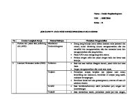
1
3 2 1. 2. 3. 4. 5.
Engine oil pressure gauge Voltmeter Coolant temperature gauge Transmission oil temperature gauge Service hour meter
This instrument panel consists of an engine oil pressure gauge, coolant temperature gauge, voltmeter, transmission oil temperature gauge, service hour timer and alarm unit. The alarm unit includes the engine oil low pressure alert, high coolant temperature and transmission oil temperature alert, alternator fault alert, neutral signal indication and preheating signal indication (Spare).
4
5
If you need to cold start the machine, preheat the engine before starting until the pointer of the gauge points to normal range because the oil pressure may be lower than normal in cold weather. 3.Coolant Temperature Gauge This coolant temperature gauge range should be between 40°C~100°C while the machine is traveling normally. If the temperature is too high, the alert indicator will turn on. Then reduce the engine speed to let the pointer return to normal range. Stop the machine to check the coolant level if it is necessary.
1.Engine Oil Pressure Gauge The range of the engine oil pressure gauge is between 0 bar-10 bar(about 0 MPa ~1MPa), the normal range is between 1 bar-10bar. If the engine oil pressure is too low, the alert indicator will turn on. 2.Voltmeter It indicates the voltage of the battery. Normal voltage is about 24-28 volts. When the voltage is below 24 volts or over 28 volts, the voltage alert indicator will flash to alarm.
4.Transmission Oil Temperature Gauge This gauge is used to indicate the oil temperature of the toruqe converter. Its range is between 50°C~120°C. If the temperature is too high, the alert indicator will turn on. Then reduce the work load to let the pointer return to normal range. 5.Service Hour Meter This meter is used to record the engine running time.
26 Operation Manual Other Controls
Other Controls
1. 2. 3. 4. 5. 6. 7. 8.
Throttle control lever Shift control lever Steering control lever Service brake pedal Decelerator pedal Service brake pedal lock lever Shift lock lever Horn button
9. Blade control lever 10. Ripper control lever 11. Pin lock cylinder button(Unavailable)
27 Operation Manual Other Controls
Accelerator Control Lever
Decelerator Pedal
This lever is used to control the engine rotating speed and the output power.
Depress this decelerator pedal down to lower the engine rotating speed.
L:Idler position H:High speed position
Shift Control Lever Three forward speed and three reverse speed are available. Operate the lever slightly to change the running speed of the machine.(F: forward, R: reverse, N: neutral)
Steering Control Lever Push one of the steering control lever to the medium position of the stroke, then the machine will get a big turning in the lever turning direction.
WARNING:When the machine is traveling to the top of a slope, or dump the soil from a cliff, it will accelerate suddently due to load reducing, depress down the decelerator pedal at this time to reduce speed.
Push the lever to the end can realize spot turn.
Service Brake Pedal Depress down the two service brake pedal simultaneously to engage the service brake. Push one of the two steering control lever to the medium position and depress down the service brake pedal on the same side, then the machine will realize spot turn at the same direction.
Brake Lock Lever This lock lever is used to lock the service brake pedal during parking. Depress down the service brake pedal, and turn the lever to LOCK position, then the service brake pedal will be locked. Depress down the service brake pedal, and turn the lever to UNLOCK position, then the service brake pedal will be unlocked.
WARNING:Do not step on the service brake pedal if engagement is unneeded.
WARNING:Lock the service brake firmly after parking.
28 Operation Manual Other Controls
Shift Lock Lever This lever is used to lock the shift control lever while parking.
NOTICE:If the machine stops working for a long time, push the shift control lever to NEUTRAL position, and turn the lock lever to LOCK position.
Generally, the blade control lever stays at (2) position. Push the lever to position (1), the blade will raise; push it to position (3), the blade will lower; push it to position (4), the blade will float.
The lever can not reset to position (2) when it is pushed to position (4). When operating the straight blade, push the lever to position A, the blade will tilt right, push it to position B, the blade will tilt left. The blade can tilt at position (1), (2), (3). Position A and B are only used for straight blade.
Blade Lock Button Press this button to lock the blade control lever, and pull it up to unlock it. WARNING:When parking or repairing, lower the blade onto ground and lock the button.
When the tilt cylinder reaches the stroke end, push the control lever back to position (2). Do not tilt the blade when it is at highest or lowest position.
Ripper Control Lever Generally, the ripper control lever stays at position (2), push the lever to position (1), the ripper will raise; push it to position (3), the ripper will lower. 6. Blade Control Lever
29 Operation Manual Others
This is a seat which is featuring in mechanical suspension and hydraulic shock absorption. It can be adjusted in the aspects of fore-and aft direction, height, backrest angle , seat tilting angle, armrest angle, suspension stroke, headrest angle and weight to meet the need of different drivers in various working conditions. Make sure that the operator can depress down the pedal to a full stroke after adjusting the seat . Always adjust the seat by seating in it. 1. Fore-and-aft adjustment
Ripper Lock Button .Fore-and-aft adjustment max. 210mm. Press this button, the ripper will be locked; pull up the button, the ripper wil be unlocked. Operate the ripper after it is unlocked. CAUTION:Lower the ripper onto ground and lock it when parking or repairing.
2. Armrest angle adjustment
Others CAUTION: The seat provided on this machine meets the standard of ISO7096.
CAUTION: The maximum supporting capacity of the armrest is 50KG. 3. Seat depth adjustment and seat tilting
30 Operation Manual Others
adjustment
6.
Nonretractable seat belt
4. Document box
7. Weight adjustment and suspension function
5. Backrest angle adjustment. 8.
Infinite adjustable lumber support
9. 3-step height adjustment by lifting the
31 Operation Manual Others
seat top
CAUTION: Do not adjust the seat while the machine is running, otherwise serious accident could be resulted!
The retractor of the seat belt is located on the right rear side of the seat; insert the buckle into the retractor, the retractor will lock the buckle.
A red button is beside the opening of the retractor, press it down, the buckle will spring up from the retractor.
Seat Belt CAUTION: The machine is equipped with seat belt by Liugong before transporting it to the destination. Its quality and installation instruction has met the standard of ISO6683. The seat belt supplied by Liugong is nonretractable. Fasten the seat belt before operating the machine. Before using the seat belt, check the seat belt for wear and tighteness condition, replace if necessary. Contact with your LiuGong dealer for the seat belt replacement. Adjust the length of the seat belt before use to ensure that the seat belt functions safely and provides comfort. Adjust the length of the seat belt by turning the buckle on the seat belt.
Before using the seat belt, first check the buckle of the seat belt is normally locked and released.
32 Operation Manual Engine Starting
Rearview Mirrors A rearview mirror is provided in front of the cab. Before operating the machine, adjust the rearview mirrors and make sure the driver has a good rear vision when sitting on the seat. Rearview mirror adjustment
Check the bolts and nuts at those positions where they are easy to loosen, especially on air filter, carrier roller bracket and track shoe stud for tighteness condition. Tighten them if necessary. 3. Check circuit Check the circuit for damaged wire, short circuit or loose terminals. 4. Check coolant level
Loosen the connection bolts between the rearview mirror bracket and the cab, turn the bracket to adjust the rearview mirrors to proper position. Loosen the connection bolts between rearview mirror and the bracket, turn the rearview mirrors to adjust the elevation. After completing the above-mentioned adjustment, tighten the bolts.
Engine Starting Check Before Starting Check the machine before starting. This is quite critical to operating safety. 1. Check for oil leakage and water leakage Inspect around the machine for oil leakage and water leakage, etc. Pay special attention to the high pressure fittings, hydraulic cylinder, final drive, track roller, floating seal in carrier roller and the water tank for sealing condition. Repair immediatey if any abnormal cases happens. 2. Check bolts and nuts
(1): Water tank cover
Unscrew water tank cover (1) to check whether the coolat is at specific level. Replenish coolant if necessary. Replenish coolant only after the engine is stopped. Refill water until it overflows from the water tank, then start the engine and let it run at idle speed for 5 minutes, check again, refill water if the level is still lower than stipulated. Check whether there is a water leakage if the refill capacity increases abnormally.
33 Operation Manual Engine Starting
WARNING:If the coolant it too hot, unscrew the tank cover (1)slowly to release the pressure before opening in order to prevent personal injury by hot water.
Unscrew the fuel tank cover and take out fuel dipsick G to check the fuel level.
5. Check engine oil level at oil sump tank
F
G 1
F: Oil fiiller G: Engine oil dipstick
(1) After the engine is shut down, take out oil dipsitck G and check the oil level at mark "ENGINE STOP". (2) If the engine is at idle state, first to make sure whether the engine oil pressure gauge and coolant temperature gauge is at normal range, then take out oil dipstick G and check engine oil level at mark "ENGINE IDLING". If it needs to replenish engine oil, refill from oil filler F.
G: Fuel dipstick 1. Fuel tank cover
Replenish fuel through fuel strainer every time after the machine finish working. The machine should be filled with fuel before operating to prevent air coming into the fuel piping.
(3) Engine oil specification depends on the ambient temperature. For more information, please refer to "Recommended Fuel, Coolant and Lubricant" on page 108.
Fuel tank capacity:480L.
(4) Park the machine on flat ground when checking the oil level. When replenishing oil, the level should be not beyond H on the disptick.
7. Check transmission oil level (including gearbox, torque converte, clutch)
6. Check fuel level
WARNING:Do not overflow fuel when refilling to avoid causing fire!
Check the transmissin oil level with dipstick G. If necessary, refill oil through strainer F. The transmission oil specification depends on the ambient temperature. For more information, please refer to "Recommended Fuel, Coolant and Lubricant" on 108. Shut the engine down before checking the oil level.
34 Operation Manual Engine Starting
The oil level should reach H mark if the machine works on a slope with 20°gradient.
2. Mount and dismount the machine according to the safety regulations.
F G
G: Dipstick F: Strainer
8. Check service brake pedal stroke Then standard stroke is 110-130mm with engine running(operating force is 15 kg) while 75 mm when the engine is shut down. The brake performance is poor if the pedal stroke exceeds 190mm. Please refer to"Other ComponentsAdjust" on 61 section for adjustment. 9. Check the disconnect switch to see whether it is open CAUTION: Before start the engine, make sure no personnel work on or around the machine except for the driver. Make sure the machine is under control at any time.
Engine Starting 1. Turn on the battery disconnect switch. After the battery disconnect switch is turned on, the key will point to I position..
3. Close the left and right door of the cab. Check the seat belt for normal condition and fasten it. CAUTION: The electrical system has Neutral/Start Interlock protection function; the engine can start only when the shift control lever is at NEUTRAL position .This can avoid the accident that produced when the machine is started suddenly. 4. Insert the start switch key and turn clockwise to I position to turn on the power. Hoot the horn to warn that the machine is going to run
35 Operation Manual Engine Starting
CAUTION: Start motor operation should not exceed 15 seconds. If the engine doesn't start after 15 seconds, release the start switch at once. Wait 30 seconds before trying to start again. If the engine can not be started for three times, wait for at least three minutes before trying again to prevent damage to the start motor. 5. Warm up the engine at idle speed of 650~750 rpm after the engine is started. Check the coolant temperature gauge. Run the engine with full speed only after the coolant temperature of the engine reaches green zone. 6. Check the readings of all the gauges to make sure they are in the normal range. Check that all the lights, indicators, horn, windshield wiper and brake lights work normally. 7. Check the service brake, parking brake system for normal condition.
36 Operation Manual Operation Techniques
Operation Techniques Operation Information Follow these basic instructions when you are operating the machine. CAUTION: Before start the engine, make sure no personnel work on or around the machine except for the driver. Make sure the machine is under control at any time. 1. Raise the blade or ripper high enough to go over any obstacles. 2. Before disengaging the parking brake, depress the service brake pedal in order to prevent the machine from moving 3. Make sure the machine has best visibility and best stability when working. 4. Reduce the engine speed when turning and go over a hill. WARNING: Personal injury or death can result from falling material. Remove any suspensions and watch out sliding material. CAUTION: Never set the blade and ripper in the float position to avoid blade and ripper damage.
1.Brake lock lever, at LOCK position 2.Shift lock lever,at LOCK position 3.Steering control lever 4.Shift control lever, at NEUTRAL position 5.Accelerator control lever
2. Adjust the driver ’s seat, make sure that the operator can depress down the pedal to a full stroke after adjusting the seat. 3. The shift lock lever (2) is at LOCK position.
Running Operation of the Bulldozer 1. Check all of the control levers before starting.See following figure.
4. Lower the blade and ripper onto ground. Engage the blade lock button and ripper lock button.
37 Operation Manual Operation Techniques
(h) Stop and check the engine if the engine oil pressure indicator turns on and the buzzer sound intermittently. 7. Check the machine surroundings for safety before traveling. 8. Control levers operation: (a) Unlock the blade lock button and ripper lock button. (b) Raise the blade control lever and ripper control lever over ground for 40-50cm.. 5. Start the engine. Push the accelerator control lever to idle position first, then turn the start switch key to start position. Release the start switch key after the engine has been started. Then key will reset to ON position. If the engine fails to start, wait for 2 minutes before restarting. Do not start the machine for over 20 seconds. If the fuel is used up, refill with fuel first then refill the fuel filter to exhaust air in the fuel system before working again. 6. Check after the engine is started: (a) Let the engine run at idle speed until the engine oil pressure indicator turns green.
1.Blade lock button 3.Blade control lever
(b) Push the accelerator control lever to let the engine run at medium idle speed for 5 minutes. (c) Do not let the engine run at idle speed or high idle speed for over 20 minutes. If the engine needs to run idly indeed, add loads to it at times to increase to medium speed. (d) Check all off the monitors, indicators for normal condition after the engine is warmed up. (e) Let the engine run with low load until the coolant temperature mointor turns to green zone. (f) Check the exhaust air color for normal condition, also check for abnormal noise or vibration. (g) Avoid accelerating suddenly before the engine is warmed up.
2.Ripper lock button 4.Ripper control lever
(c) Depress down the cross part of the left and right sevice brake pedal, unlock the brake lock lever, then release the brake pedal.
38 Operation Manual Operation Techniques
(f) Push the shift control lever to desired position, then start the machine. (g) Operate the accelerator control lever to increase engine speed. (h) Operate the shift control lever to change the desired speed.
1.Decelerator pedal 2.Cross part of left and right pedal
(i) Shift between forward and reverse. Shift the running speed in forward to reverse direction can prevent the machine from being shocked. Depress down the decelerator pedal to reduce engine speed, then push the shift control lever to desired speed position, finallly release the decelerator pedal to increase engine speed.
Steering Operation of the Machine 1. Sharp turn to left and right Push the left /right steering control lever partially to half stroke, then the machine will turn sharply to left or right direction. 2. Normal turn to left and right 1.Brake lock lever
1.Brake lock lever, 2.Shift lock lever 3.Steering control lever 4.Shift control lever 5.Accelerator control lever
(d) Release the shift lock lever. (e) Depress down the decelerator pedal to reduce the engine speed so that the machine can avoid shock when starting.
Push the left /right steering control lever fully to the end, the left /right clutch will seperate from each other, then engage service brake, the machine will turn gradually to left or right direction.
39 Operation Manual Operation Techniques
Machine Stopping Push the accelerator control lever to idle position to reduce the engine speed.Then push the shift control lever to NEUTRAL position. Depress down the cross part of left and right service brake pedal, the machine will stop. Then lock the brake lock lever and shift lock lever.
1.Blade lock button 3.Blade control lever
1.Decelerator pedal 2.Cross part of left and right pedal
2.Ripper lock button 4.Ripper control lever
Press the blade lock button and ripper lock button. CAUTION: Park the machine on a flat and hard ground as much as possible. 1.Brake lock lever, 2.Shift lock lever 3.Steering control lever 4.Shift control lever 5.Accelerator control lever
Push the blade control lever and ripper control lever to LOWER position to lower the blade and ripper onto ground.
Engine Stopping Let the engine run at idle speed for five minutes to cool down. Turn the start switch key to OFF position, the engine will stop running. Take out the key. CAUTION:Stopping the machine before the engine cools down will reduce the engine service life. Neve stop the machine suddenly unless under emergency.
40 Operation Manual Operation Techniques
Operation during Cold Weather 1. A severe cold weather will lead to a difficult start to the engine, also could cause coolant frozen. Use specific oil and coolant according to "Recommended Fuel, Coolant and Lubricant" on 108. 2. If the ambient temperature drops below O° C, add anti-freeze into the coolant to avoid frozen. For more information, please refer to "Clean the internal surface of the cooling system." on 59. 3. Use fuel, hydraulic oil and lubrication with low viscosity and add antifreeze to the coolant. Refer to "Recommended Fuel, Coolant and Lubricant" on 108 in the Maintenance Manual for particular oil brands. 4. In severe cold areas, use anti-cold batteries. As the ambient temperature drops, the electrolyte may be frozen. In order to prevent battery capacity loss, cover the battery or move it to a warm place and fix it the next day, then the engine can be started easily at the next day. 5. Thoroughly clean sludge, water or frozen snow on the machine to avoid them entering into the seam and damaging sealing performance. 6. Park the machine on a dry and hard ground. If impossible, park the machine on the wooden board. The wooden board can prevent the machine from being frozen. CAUTION: Drain the coolant compeltely in winter night if the coolant is not added with anti-freeze. Drain the water from the oil cooler together. CAUTION: Use standard anti-freeze only. It is forbidden to use carbinol or ethanol as anti-freeze because that will cause engine fault. 7. Clean the cooling system completely before adding the anti-freeze.
8. When the weather turns warm, drain out the anti-freeze (except for permanent type) and clean the cooling system, then refill with clean water. DANGER:Anti-freeze is flammable, keep it from fire! 9. Remove the snow or water on the cylinder piston rod. The cylinder seals are easy to damage if the piston rod is frozen. NOTICE: When the ambient temperature drops, the capacity of the battery will also drop. If the battery charge ratio is low, the battery electrolyte may freeze. Maintain the battery charge as close as possible to 100%. Insulate it against cold temperature to ensure the machine can be started easily the next morning. Measure the specific gravity and calculate the charge rate from the following conversion table. Electrolyte temp Charging rate 100% 90% 80% 75%
20°C
0°C
-10°C
-20°C
1.28
1.29
1.30
1.31
1.26 1.24 1.23
1.27 1.25 1.24
1.28 1.26 1.25
1.29 1.27 1.26
If the electrolyte level is low, add distilled water in the morning before beginning work. Do not add water after the day’s work to prevent the electrolyte in the battery from freezing in the night.
Downhill Operation Push the left /right steering control lever partially to half stroke, then the machine will turn sharply to left or right direction.
41 Operation Manual Operation Techniques
Push the left /right steering control lever fully to the end, then the machine will turn gradually to left or right direction.
WARNING: If the fuel level in the fuel tank becomes low when working on slopes, the engine may suck in air because of the angle of the machine or the swaying of the machine, this can make the machine stop. Therefore, be careful not to let the fuel level in the fuel tank become too low.
Operation in Water Before operate the machine in water, first to check the water depth and soil condition underwater to avoid any sinkage accidents caused by these factors. Keep the ilder gear center above the water surface.
Cautions in Downhill Operation: (1) Do not park the machine on a slope except for special situation. If it really needs, park the machine on a slope with the front end at downhill side and lock the service brake pedal. If the gredient is big, insert the blade slightly into soil to prevent movement of the machine. (2) It is prohibited to drive the machine on a slope with a gradient over 30 degree. Do not drive the machine reversely when go uphill. WARNING: Do not drive the machine across or turn the machine on a slope. Drive in straight direction as much as possible. CAUTION: Do not shift gear on the slope or try to drive over any obstacles. (3) Before go down the hill, first depress the left and right brake pedal, turn th shift control lever to 1 position, then release the service pedal slowly. (4) Select a slow speed when go downhill and use engine as brake. If the engine is overspeeded and cause danger, use the brake pedal instead to reduce speed.
Wash the machine with fresh water if the machine works in sea water or in other corrosive envrionments.
Operation in Desert Cover the machine with suitable material when the machine travels in desert or dusty envrionments.
42 Operation Manual Machine Operation
Machine Operation Dozing Cutting into hard or frozen ground or ditching For digging and ditch excavation of hard or frozen ground, use a straight or angle blade to improve digging efficiency. If the ground is very hard, use a ripper instead.
Side Dozing Use angle blade when dozing the soil by one side.
Leveling To finish the ground to a flat surface after digging or leveling, do as follows: 1. Put a full load of soil in front of the blade and operate the blade up and down in small movements while traveling forwrd. 2. Place the blade at FLOAT and travel at low speed in reverse while pulling the blade over the ground suface.To prevent damage to the blade, be careful not to travel over any stones or rocks.
CAUTION: D not root up the trees or stumps by angle blade. Try not to start , brake or turn suddenly or sharply during dozing operation.
Blade Adjustment Angle blade adjustment 1. Rotation angle adjustment
43 Operation Manual Machine Operation
The blade can be adjusted to 25°at both ends.
(1) Raise the blade 300-400 mm above the ground, then put blocks under the frame so that the blade does not drop down.
(1) Raise the blade 400-500 mm above the ground, then put blocks under the frame so that the blade does not drop down.
(2) Remove pins on the left and right sides, then remove arm from the frame.
(2) Loosen the bolt of the brace, insert a suitable bar into hole of the brace, and turn it.
1.Pins 2.Arm
1.Bolt 2.Hole
(3) Insert arm into the desired position on the bracket on top of the frame (2 brackets on each side), and insert pin.
(3) Tilt the blade to desired position, then tighten the bolt. Generally, the brace length is about 1338 mm, and the blade tilt must be within 500mm.
WARNING:Be careful after the arm is removed because the blade may rotate.
WARNING :Do not tilt the blade above 500mm to prevent unexpected accidents.
2. Angle blade tilt adjustment Maximum tilt of the blade is 500mm.
When turning the brace with bar, keep the blade above the ground, then tilt it. 3. Adjusting shim adjustment
44 Operation Manual Machine Operation
The standard thickness of the adjusting shim on the blade lift cylinder piston rod is 4mm.
(1) Adjust the shim thickness. Make sure that the spheric joint axial clearance is less than 1mm.(See arrow direction in following picture)
Remove some of the shims from the piston rod of blade lift cylinder to adjust the clearance, keep the clearance between 0.2~ 0.6mm. Straight blade adjustment 1. Straight blade tilt (1) Operate the blade control lever to tilt the blade to 425mm. If it is necessary, adjust the length of brace to tilt the blade to 500mm.Generally, the brace length is about 1287 mm, and the blade tilt must be within 500mm.
(2) Remove shim(1) and tighten the bolt (2)to clear the spheric joint clearance. Measure clearance A, then remove bolt (2).Install shim (1) with thickness A+1, then tighten bolt (2). Make sure that the spheric joint can move freely after the bolt is tightened.
WARNING :Do not tilt the blade above 500mm to prevent unexpected accidents.
L
L:Length
2. Adjusting shim adjustment
1.Shim 2.Bolt A.Clearance
45 Operation Manual Machine Operation
Prolong the Bulldozer’s Service Life Observe the following procedures to maintain the machine. 1. Choose the suitable model with different track according to the soil condition. 2. Try to avoid trackslip during operation. If the track slipes, reduce work load until this phenomenon disappears. 3. Try not to start, accelerate, brake and turn sunddenly and sharply as much as possible. 4. Try to drive the machine straightly as much as possible. Do not always turn to one side. It will be better to turn alternately with maximum turning radius. 5. During dozing operation, if the driver comes across small slopes in the way, drive the machine reversely to flat ground then level the slope. 6. Never attempt to drive the machine over any obstacles, otherwise the idler gear or sprocket will loose contact with the ground. 7. Before starting to work,clear away the big stones and other obstacles on the job site.
Leaving the Machine 1. Close the left and right door. 2. Use the ladder and the handrail when you get off the machine. Face the machine and use both hands. Make sure that the steps are clear of debris before you dismounting. 3. Inspect the engine compartment for debris. Clean out any debris and paper in order to avoid a fire. 4. Remove all flammable debris in order to reduce a fire hazard. Dispose all debris properly. 5. Turn the battery disconnect switch to the OFF position. 6. If the machine is not filled with anti-freeze at ex-factory, after the machine parks in winter, open all water drain valves of the engine in time, discharge all coolant in the cooling system and air conditioner system so as to prevent the machine from being cracked by frost. If the machine has been filled with antifreeze at ex-factory, refer to the instructions of the anti-freeze labels. 7. Fix all covers, lock all equipments and remove the key.
46 Operation Manual Machine Operation
Storage
After Storage
Before Storage
If the machine has been stored without carrying out the monthly rust-prevention operation, do the following procedures before using it.
1. Clean and dry every part of the machine and store it in a dry warehouse. If the machine has to be stored in the open air, park the machine on a concrete ground and cover with canvas. 2. Before storage, refill the oil tank, lubricate every moving pin & shaft and change hydraulic oil. 3. Paint a thin layer of grease on the exposed part of hydraulic oil cylinder piston rod.
1.
Remove the engine oil pan and drain plugs of other tanks to drain out residual oil.
2. Remove the cylinder head, llubricate every air valve and lever. Check the air valve for normal condition. 3. In order to exhaust the air in the hydraulic system, run the engine with idle speed and do as follows:
4. Remove batteries from the machine and store in a separate place.
4. Extend and retract the cylinder repeatly for 45 times, stop the piston at 100mm from the stroke end.
5. If the air temperature is below 0°C, add antifreeze in coolant in advance.
5. Then extend and retract the cylinder repeatly for 3-4 times to the stroke end.
6. Set all of the controls as belows:
NOTICE:If the engine runs at high speed or the piston runs to its stroke end at the beginning, then the piston gasket may be damaged by the mixed air.
(a) Push the shift control lever to NEUTRAL. (b) Push the accelerator control lever to IDLE position. (c) Push the blade control lever to HOLD position.
6. After start the engine, keep it run until it is warmed up.
(d) Push the brake pedal to UNLOCK position.
Before Reuse 1. Lubricate all moving pins and shafts.
During Storage
2. Before starting the machine, wipe off grease on the hydraulic oil cylinder piston rod.
1. Start the machine once every month and run every system, and lubricate every parts of the moving pins and shafts. Meanwhile, charge the battery.
NOTICE: If the machine is not coated with antirust additive per month during storage, please consult with Liugong dealer.
2. Before starting the machine, wipe off grease on the hydraulic oil cylinder piston rod. After operation, paint a layer of grease on it. WARNING: To avoid personal injury or death, when working with anti-freeze inside the room, open the windows for ventilation.
47 Operation Manual Machine Operation
Transportation Information Transportation of the Machine
8. Lower the blade and push all of the control levers to following position. (a) Shift control lever to NEUTRAL position. (b) Blade control lever to HOLD position.
CAUTION: Obey the correlative laws govern characteristics of the load (weight, width, and length).
Note:
Investigate the travel route for overpass clearances, Make sure that there will be adequate clearance for the machine.
1. If the blade length is longer than trailer width, adjust the blade angle or remove it to reinstall.
Clean ice, snow, or other slippery material from the loading dock and from the truck bed before you load the machine onto transport machine. This will prevent the machine from slipping in transit. This will also prevent a the machinn from moving while the during transportation.
2. Take anti-rust measures if it needs to transport the machine on water for long distance.
Perform loading according to the following steps: 1. Chock the trailer wheels or the truck wheels before you load the machine.
2. When the machine is loading on the trailer or truck, it is forbidden to turn. 3. Shut down the engine, push all of the levers and switches to NEUTRAL or OFF position. Take off the start switch key. 4. Turn the disconnect switch to OFF position. 5. Lock the door and remove the key. 6. Turn the battery disconnect switch to OFF position. 7. Place the bulldozer properly onto the trailer. Chock the tracks of the bulldozer and fasten it with steel wires to avoid movement during transportation.
(c) Brake lock lever to LOCK position.
3. Coat the exposed pars of the cylinder piston rod with anti-rust agent.
48 Operation Manual Lubrication Chart
Lubrication Chart
49 Operation Manual Lubrication Chart
Lubrication Table Item
Lubrication position
total
Lubricant
Tool
Lubrication interval(hour)
1
Cylinder support shaft
4
Grease
Grease gun 250
2
Cylinder spherical hinge
2
Grease
Grease gun 250
3
Brace spherical hinge
2
Grease
Grease gun 250
4
Fan belt
1
Grease
Grease gun 250
5
Tensioner
1
Grease
Grease gun 250
6
Tensioner bearing seat
1
Grease
Grease gun 500
7
Brace lead screw
2
Grease
Grease gun 250
8
Cylinder bracket
2
Grease
Grease gun 250
9
Engine oil sump tank
1
Engine oil
10
Steering filter element
2
11
Brake pedal
6
Grease
Grease gun 2000
12
Universal joint
8
Grease
Grease gun 1000
13
Clean the primary filter
1
14
Throttle flexible shaft
3
Grease
Grease gun 2000
15
Brake lock lever
1
Grease
Grease gun 2000
16
Shift control lever
3
Grease
Grease gun 2000
17
Blade control lever
3
Grease
Grease gun 2000
18
Strut
2
Grease
Grease gun 1000
19
fuel primary filter
1
20
final drive gear box
2
Engine oil
21
Rear axle
1
Engine oil
22
Work cylinder
1
Engine oil
23
filter element of work cylinder
1
24
brace of idler gear
2
Grease
Grease gun 250
25
Main shaft of equalizer bar
1
Grease
Grease gun 250
26
Fuel filter
1
27
Engine oil filter
1
Grease
Grease gun Replace every 250hours
28
Spheric hinge of tilt cylinder
2
Grease
Grease gun 250
Spheric joint of ripper (optional)
18
Engine oil Replenish every 10 hours, replace every can 250hours 250
Clean every 500hours
Clean every 250 hours Engine oil can Engine oil can Engine oil can
Check every 250 hours, replace every 1000 hours Replenish every 10 hours, replace every 1000hours Check every 250 hours, replace every 1000hours Replace every 1000 hours
Replace every 250 hours
Replace every 250 hours
50 Maintenance Manual Run-in
Maintenance Manual
3. Check engine oil level, hydrauli oil level and coolant level. 4. Check the hydraulic system for leakages.
NOTICE: Please perform the maintenance procedures at the intervals according to this manual. Proper maintenance will extend the service life of the machine and provide safer operation.
5. Check the connections of all control levers and flexible shaft.
Run-in
CAUTION: Check oil level according to the relevant operation regulations.
The run-in of new machine is an important procedure for prolonging of the service life of the machine, eliminating fault and avoiding accidents. The user must read these guidelines for run-in a new machine and how to operate and maintain the machine after purchase.
Work should be done after the finish of run-in
Run-in-Requirements for New Machine
3. Check the hydraulic system for oil leakage.
1. Run-in of a new machine is 100 hours.
4. Replace the fuel filter, work oil tank filter and clean the shift primary filter.
2. Run the engine with idle speed for five minutes after starting the machine. Start the machine at low speed. Slowly increase speed.
Maintenance Interval Schedule
3. Run-in should be done averagely in gears of F1, F2, F3, F4, R1, R2, R3. 4. Start the machine at low speed. Slowly increase speed. Always avoid starting, speeding up, turning and braking suddenly except for emergency cases. 5. Do not drive the machine with heavy load. Do no drive it at high speed. 6. Pay attention to the lubrication condition of the machine. Replenish or replace the lubricant or grease according to maintenance intervals. The following must be done after the first 8 hours of operation during the run-in period. 1. Check the tightness of all the bolts and nuts . 2. Check the fan belt, engine belt and air conditioner compressor belt for tighteness.
6. Check temperatures and connections of the electrical system, power supply of the alternator, lights and the turn signal lights.
1. Check the tighteness of all bolts and nuts. 2. Check the condition of the fan belts, engine belts and air conditioner compressor (optional) belts.
NOTICE: Read and understand all the safety instructions, warnings and indications before any operations or maintenances. The maintenance intervals stated in this manual are determined according to the service hour meter or calendar intervals shown (daily, weekly, monthly, etc). Liugong recommends that maintenance should be performed according to whichever of the above-mentioned intervals occurs first. Under extremely severe, dusty or wet operating conditions, more frequent lubrication than is specified in the "Maintenance Intervals" chart may be necessary
51 Maintenance Manual Maintenance Interval Schedule
. Maintenance table Item
Service item
Measures
Check before starting 1
Check for oil and water leakage
Check
2
Check bolts and nuts
Check and tighten
3
Check circuits
Check and tighten
4
Check coolant level
Check and replenish
5
Check engine oil level
Check and replenish
6
Check fuel level
Check and replenish
7
Check transmission oil level
Check and replenish
8
Drain the sediment out from the fuel tank
Drain out the water and sediment
9
Check dust indicator
Check and clean the air filter element
10
Check stroke of brake pedal
Check and adjust
Maintenance at first 250 hours 1
Fuel filter
2 3
Steering clutch box(include transmission andReplace oil and clean the primary filter torque converter) Wor oil tank and filter Replace oil and change the element
Replace the strainer
4
Final drive box
Replace oil
5
Engine valve lash
Check and adjust
Maintenance at every 250 hours Lubrication(check and lubricate the following positions) 1
Fan belt pulley
1position
Tensioner and carrier
2 positions
Brace lead screw
Straight tilt blade:1 position, angle blade: 2 positions
Cylinder bracket shaft
2 positions
Cylinder bracket
4 positions
Tilt cylinder spheric joint
Straight tilt blade:1 position
Brace spheric joint
Straight tilt blade:1 position
Arm spheric joint
3 positions
Jack spheric joint
2 positions
All spheric joint of ripper
18 positions
2
Engine oil sump tank and filter
Drain oil and replace filter element
3
Gear shift filter and steering filter
Replace filter element
4
Final drive box
Check oil level and replenish
5
Work oil tank
Check oil level and replenish
6
Alternator drive belt
Adjust the tension force
7
Water pump drive belt
Adjust the tension force
8
Battery electrolyte
Check the electrolyte level
9
Fuel filter at fuel tank bottom
Clean
Maintenance at every 500 hours l
Fuel filter
Replace filter element
2
Breather cap
Wash
3
Fan belt
Adjust the tension force
52 Maintenance Manual Maintenance Interval Schedule
Maintenance table Item
Service item
Measures
Maintenance at every 1000 hours Lubrication(check and lubricate the following positions) 1
Universal joint
8 positions
Strut
2 positions
Brace of idler gear
2 positions
2
Water radiato fins
Check and clean
3
Steering clutch box
Replace oil and wash the primary element
4
Final drive box
Replace oil
5
Work oil tank and filter
Replace oil and the primary element
6
Undercarriage
Check and add grease
7
Turbocharger
Check the rotator clearance
8
Rust preventer
Replace the strainer
Maintenance at every 2000 hours Lubrication(check and lubricate the following positions) 1
Equalizer bar shaft
l position
2
Brake pedal
5 positions
3
Breather cap of engine crankcase
Wash
4
Turbocharger
Wash
5
Engine valve lash
Check and adjust
6
Engine shock absorber
Check or replace
Maintenance at every 4000 hours 1
Water pump
2
Fan belt pulley and tensioner
Check the fan belt pulley for loose condition, also check for water leakage Check for loose condition
Maintain when required l
Air filter
Clean or replace
2
Cooling system
Wash the internal surface and replace coolant
3
Track tension degree
Check and adjust
4
Track bolts
Check and tighten
5
Cutting edges and end bits
Reverse or replace
Maintenance at first 250 hours
5. Engine valve lash.
Maintain the machine after it has worked for 250 hours.
For more information, please refer to the Maintenance table, "Maintenance at every 500, 1000 and 2000 hours" section.
1. Fuel filter 2. Steering clutch box(includes transmission and torque converter) 3. Work oil tank and filter 4. Final drive box
Every-250-Service Hours 1. Lubricate every grease fitting with grease. 2. Lubricate fan belt pulley : 1 position
53 Maintenance Manual Maintenance Interval Schedule
3. Lubricate tensioner and tensioner bracket : 2 positions. 4. Lubricate strut:1position ; straight tilt blade:1position, angle blade: 2 positions. 5. Lubricate cylinder bracket ,2 positions. 6. Lubricate tilt cylinder spheric joint (straight tilt blade): 1 position. 7. Lubricate brace spheric joint (straight tilt blade): 1 position. 8. Lubricate jack spheric joint (straight tilt blade): 2 positions. 9. Lubricate the blade cylinder joint, 2 positions. 10. Lubricate all the articulated joints of the ripper. Upper linkage : 8positions; top of cylinder piston rod: 2 positions; lower frame pin: 4 positions; lower frame shaft: 4 positions.
(2) Remove the engine oil filter strainer and the by-pass engine oil filter strainer, discard them. Fill the new engine oil filter strainer and the by-pass engine oil filter strainer with clean oil and coat the gasket with few oil,then install them onto the filter mount. Tighten the gasket for 3/4~1 turn after it contacts with the mounting surface. Refill engine oil from filler F after new filters are installed. Then let the engine run at idle speed, check the engine oil level. The grease specification depends on the ambient temperature, for more information, please refer to "Recommended Fuel, Coolant and Lubricant" on 108. Replace the oil every 6 months.Before installing the new strainer, fill the strainer with engine oil. NOTICE: Use genuine Liugong brand strainer.
F
G
F: Oil filler G: Engine oil dipstick
11. Check engine oil sump tank and filter. (1)Remove the cover. Unscrew the oil drain plug and oil drain valve to drain oil. Tighten them after drainage is finished.
3. Check transmission oil filter and steering oil filter. (1) Remove bolt (1) and pull up cover (2), take out the strainer and valve. Remove nut( 4), take out the strainer from the filter.Clean the internal surface of filter housing and those removed parts. Then install new strainer to the filter. Do use genuine strainer of liugong.
54 Maintenance Manual Maintenance Interval Schedule
G: Plug
2. Check work oil tank Lower the blade and ripper onto ground, stop the engine and check the oil level after 5 minutes. If the oi leve does not reach the specific mark, refill oil from oil filler F.
1.Bolt 2.Cover 3.Strainer 4.Nut
2. Check final drive box (1) Remove plug (G), if the grease level is not enough, refill grease through the plug hole. The grease specification depends on the ambient temperature, for more information, please refer to "Recommended Fuel, Coolant and Lubricant" on 108.
F: Filler
WARNING: it is forbidden to remove the oil tank cover if the oil is hot. Turn the cover slowly to release the internal pressure. WARNING: Check the engine as usual before starting the engine.
55 Maintenance Manual Maintenance Interval Schedule
3. Check the alternator belt
The alternator belt tension: apply (w=60N) force according to the arrow direction. The deflation should not exceed 10mm, otherwise adjust it. Check the belt for damage. If the belt can not be adjusted any more or cracks, replace it. After installing a new belt, let it run for 1 hour , the check and adjust again. Do not allow the V belt contact with the V groove bottom. 4. Check water pump belt The procedures for checking and adjusting the water pump belt is the same. 5. Check battery electrolyte If the battery electrolyte level is lower than specified, (about 10~12mm lower), add distilled water. If the electrolyte level is reduced due to overflowing, add diluted sulfuric acid in the electrolyte with same concentration. Clean the bleed on the battery cover. Do not use metal funnel when adding sulfuric acid. DANGER: Keep the battery away from sparks in order to avoid as explosion! WARNING:If th electrolyte spurts to skin or clothes, wash with water immediately. 6. Drain sediment and water from the fuel tank
Open the rear cover and loosen the drain valve at the bottom of the fuel tank to drain water and sediment. Every-500-Service Hours In additional to previous checks: 1. Check fuel filter Close the drain valve at the bottom of the fuel tank. Remove the fuel filter strainer and install with a new strainer. Fill the new strainer with clean fuel before installing and coat few oil onto the gasket. Tighten the gasket with hand when installing new strainer until the gasket contacts with the filter base. Then tighten the gakset to 1/2~3/4 turn(Do not over tighten it).
56 Maintenance Manual Maintenance Interval Schedule
(3) Replenish transmission oil from the filler to specified level. 3. Check final drive box
2. Bleed Remove the bleed, wash away the accumulated dust with fuel. 3. Fan belt Check the V belt. Replace it if the following situations exist: (1) When the V belt contacts with the pulley groove; when the V belt is worn, and its surface is below the pulley outer diameter. (2) When the V belt cracks or peels. For replace procedures, please refer to "Fan belt" on 56. Every-1000- Service Hours In additional to the previors checks: Lubricate all the grease fittings. Universal joint:8 positions; half shaft bushing: 2 positions; idler gear tension cylinder : 2 positions. 1. Check radiator fins: Loosen the bolt on the water tank guard, open the guard. Blow the dust and leaves etc. on the radiator fins with compressed air, or use vapor or water instead. Check the hose of the water tank for cracks, replace if necessary. Check the hose clamp for looseness. 2. Check the steering clutch box (include the spiral gear box) and transmission (1) Loosen the oil drain plug on the transmission housing to drain oil.Tighten the plug after finishing. (2) Loosen the oil drain plug on the torque converter housing to drain oil. Tighten the plug after finishing.
(1) Remove the oil drain plug from both sides of the final drive box to drain oil, tighten the plug after finishing. (2) Refill oil into the final drive box through the plug, for more information, please refer to "Every-250-Service Hours" on 52. Refill capacity for each side: 51L. 4. Work oil tank and filter (1) Remove the oil drain plug at the bottom of the oil tank and loosen the oil drain valve to drain the oil. Tighten the oil drain valve and plug after finishing. (2) Remove bolt ,cover and strainer. Clean the removed parts and the internal surface of filter. (3) Install new strainer and refill clean oil to specific level from filler F. For more information, please refer to "Every-250Service Hours" on 52. Refill capacity: 58L.
57 Maintenance Manual Maintenance Interval Schedule
NOTICE: Use genuine Liugong brand strainer.
Close the inlet and outlet valve of corrosion resistor. Remove the corrosion resistor counterclockwise with spanner. Coat few oil on the sealing surface. When installing new elements, tighten it to 1/2 turn ~3/4 turn after the cover contacts with the sealing surface.(Do not over tighten). Open the valve after replace. NOTICE: Use genuine Liugong brand strainer. Every-2000-Service Hour In addtional to previous check:
F:Filler
Lubricate all the grease fitting. Equalizer bar:1 position; brake pedal shaft ::5 positions;
5. Undercarriage
1. Turbocharger
(1) Park the machine on a flat ground. Check the track roller, carrier roller and idler gear for oil comsumption.
The accumulated mud or dust will damage the turbocharger. Please contacat with liugong dealer for further checks or clean. Do not use wire brush or similar toos because that will damage the turbocharger surface.
(2) Loosen the bolt to check whether oil overflows from the thread. If it does, then it indicates the oil level is normal, tighten the bolt immediately. (3) If the oil does not overflows from the bolt when the bolt is removed completely, then the oil level is lower than specified, contact liugong dealer for further informatioin.
2. Enging valve lash Please contact liugong dealer for information to check the valve lash. It needs special tools for checking. Every-4000-Serive Hours In addtional to previous checks: 1. Water pump Check the belt pulley for looseness, also check the grease and water for leakage. Contact liugong dealer for repair or replace if any leakages are found. 2. Fan belt pulley and tensioner
6. Check turbocharger rotator clearance Please contact liugong dealer for checks or repairs. 7. Corrosion resistor(water strainer)
Check the rotator for looseness, also check the grease for leakage. Contact liugong dealer for repair or replace if any leakages are found.
58 Maintenance Manual Maintenance Interval Schedule
Maintenance when required Check the following items when needed: 1. Air filter (1) Check Clean the air filter if the air filter indicator turns on. Shut down the engine when checking. (2) Clean or replace the main element Remove nut (1) and the main element. Clean the internal surface of the air filter housing. Clean and check the main element. Rip off the code label every time when cleaning the main element. Install the cleaned main element.
CAUTION: Replace the main element if it has been used for 1 year or cleaned 6 times. (3) Replace gasket (2) and nut (1) if they are damaged. (4) Check the mounting nut of inner elemnt for looseness. Tighten it again if it is loose. 2. Replace the safety element(if it has been cleaned 6 times or damaged)
Main element
(1) First, remove the main element before removing the safety element. Plug the air inlet. Clean the air filter housing and take out the air inlet cover. (2) Install a new safety element to the connector, tighten with nut, then install the main element. CAUTION: Do not reuse the safety element after it has been cleaned. Do not clean or replace the air filter element when with engine running. 3. Clean method of main element (1) Clean with compressed air
1.Nut 2.Gasket
Clean the main filter element with compressed air (below 0.7MPa). First wash it out along the pleats inside the main filter element, then repeat washing the pleats along the inside and outside surface of the main filter element. Check the element after cleaning. Wear safety goggles or other protective device when working with compressed air.
59 Maintenance Manual Maintenance Interval Schedule
(2) Wash with water
Dry the elemtent with air compressed air (below 0.7MPa). Blow from inside to outside. Do not dry with heat.
Permanent Every year(fall) or Every 1000 type anti- every 2000 hours hours, or when freeze cleaning the (which come first) cooling (suitable for system or all seasons) replacing the NonEvery 6 coolant permanent months(drain in type anti- spring, add in freeze(inclu autumn) de glycol base)(only for winter) No need Every 6 months or anti-freeze every 1000 hours(which comes first)
It also works to use warm water (about 40 °C) instead of soap.
(1) Park the machine onto flat ground when it needs to clean or replace coolant.
After cleaning the main filter element, check with an light, if small holes and particles as well as damage of the washer and seal are found, replace with a new main filter element.
(2) Try to use permanent type anti-freeze as much as possible, if permanent type antifreeze is not available, use glycol based antifreeze instead. But it needs to replace the corrosion resistor strainer (water strainer)
Clean the main filter element with water (below 0.3MPa). First wash it out along the pleats inside the main filter element, then repeat washing the pleats along the inside and outside surface of the main filter element. Check the element after drying. (3) Wash with detergent Clean the grease and dust with neutral detergent, then wash with fresh water, check again after drying.
(3) Use tap water to fill the cooling system. DANGER: The anti-freeze is flammable, keep it from fire!
4. Clean the internal surface of the cooling system. Clean the Clean the internal surface of the cooling system, replace the oolant and corrosion resistor based on following table: Anti-freeze Clean cooling Replace model system and coolant intervals of replace intervals corrosion resistor
60 Maintenance Manual Maintenance Interval Schedule
See the following table for the proportion of coolant and anti-freeze.
(8) After cleaning, stop the engine. Open the water drain valve to drain water. After drain the water, close the drain valves.
Lower ambient - 5 temperature ( °C) Anti-freeze (L) 18.5
- 10
- 15
- 20
24
29
33
(9) After draining the water, clean the cooling system with cleaning agent. For cleaning agent, see the instructions for the cleaning agent.
Water
55
50
46
60.5
(4) Shut down the engine, close the water inlet and outlet valve of corrosion resistor. Unscrew the water tank cover slowly to open it.
(10)After cleaning the cooling system, drain the residual water and close the water drain valve. Refill water until the water overflows. Then let the engine run at idle speed. Open the water drain valve to refill water continuously until the clean water flows from the water drain valve. (11)Adjust the water volume when draining water to make sure the water filling and draining is at same speed so that the water tank is full of water all the time. Stop the engine when the water is clean. Close all the drain valves. Replace the corrosion resistor strainer and open the water inlet and outlet valve of it. For details of procedures for replacing the corrosion resistor, please refer to "Every1000- Service Hours" on 56.
1.Water tank cover
WARNING: Do not open the cap if the water is hot! Unscrew the cap slowly to release pressure. (5) Open the water drain valve at bottom of the water tank and at both ends of oil cooler to drain out the coolant. (6) Close the water drain valve at the bottom of the water tank and at both ends of the oil cooler. Refill water until the water overflows. Then let the engine run at idle speed. Open the water drain valve at bottom of the water tank and at both ends of oil cooler, meanwhile, refill water continuously until the clean water flows from the water drain valve for 10 minutes. (7) Adjust the water volume when draining water to make sure the water filling and draining is at same speed so that the water tank is full of water all the time.
(12)Fill with water until it overflows from the filler. (13)Let the engine run at low idle speed for 5 minutes, then at middle idle or another 5 minutes to exhaust the air in the cooling system.(The water tank cap should be opened when operating). Stop the engine and wait for 3 minutes. Refill coolant to the specific level, then tighten the cap.
Track Tension-Check 1. Inspection Stop the machine on level ground(stop with the transmission in FORWARD without applying the brake).Then place a straight bar on the track shoes between the carrier roller and the idler gear. Measure the clearance between the bar and the grouser at the midpoint. If the clearance is 20 to 30mm , the tension is standard. 2. Adjustment
61 Maintenance Manual Maintenance Interval Schedule
(1) Pump in grease through the grease fitting with a grease pump. (2) To check that the correct tension has been achieved, move the machine backwards and forwards. (3) Check the track tension again, and if tension is not correct, adjust it again.
the
(4) Continue to pump in grease until S becomes 0mm. If the track is still loose, the pin and bushing are excessively worn, so they must be either turned or replaced. Please contact with your liugong dealer.
(1) Raise the blade to a proper height and applly a block to the frame so as to prevent fall of the blade. (2) Remove the end bits and cutting edge and clean the contact surface. (3) Replace new end bits and reverse the cutting edge (or replace with new one). Tighten it to 627 土 78N·m(64 士 8kgm) . Operate it for serveral hours then tighten the nut.
Other Components-Adjust 1. Steereing brake (1) Inspection If the brake disc is worn, the brake pedal stroke will increase, which will bring difficulty to steering operation. If the pedal stroke exceeds 190mm(brake force is losing), then adjust as belows: standard stroke110~130mm, the brake force is 150N when the engine runs at idle speed, stroke when the engine stops:75mm.
WARNING: Do not loosen lubricator for one turn. Do not loosen any part other than the lubricator. Furthermore, do not bring your face in front of the grease fitting. 3. Check and tighten track shoe bolts If the track shoe bolts which are used to secure the track shoes are loose, the track shoe will break, so tighten any loose bolts immediately. (1) Tighten the track shoe bolts to 400 士 40N· m.Then ensure the nut and shoe are in close contact with the link contact surface. (2) After checking, tighten a further 120" 士 10. 4. Reverse and replace the end bits and cutting edges Reverse or replace the end bits and cutting edges before it is worn out to the blade end. If both sides of the cutting edge are worn, then replace the cutting edge.
(2) Adjustment Remove the rear cover and check. Adjust the adjusting bolt to 50N·m until the brake disc contacts witch the brake drum tightly.(Depress down the brake pedal to ensure).Then turn the adjusting bolt for 6/7 turn counterclockwise. Make sure the two brake pedals have same stroke, otherwise the brake performance could be affected. Contact with liugong dealer for replacing the brake band if the adjusting bolt size is small than 71mm. 2. Idler gear
62 Maintenance Manual Maintenance Interval Schedule
Since the idlers are forced to move forward and backward by an external force, then the guide plates will be worn out. Wear of these plates will cause the vibration of idlers from side to side or inclination of the idlers, and running off of track links from the idlers or unevenly worn idler and links may result. (1) Move the machine by 1 to 2 m on a level place, then measure clearance bewteen the trck frame and guide plate (at four places of both sides, inside, and outside) (2) If the clearance exceed 4.0 mm, loosen the fixing bolt and pull out the shim to adjust the clearance at one end to 0.5 to 1.0. Thickness of one shim is 00.5~1.0mm. Do not turn the bolt for more than 3 turns when loosening. 3. Fan belt The fan belt is equipped with auto-tensioning device, so its extension has nothing to do with V belt. When replace a new belt, check its size. Its size should be within 113 土 5mm, adjust if the value does meet the above figure. When replace V belt, replace the two belts together. 4. Undercarriage Check and adjust the track tension. The track should be tensioned than other when working on rocky envrionment. For more information, please refer to "Track Tension-Check" on 60 in When Required section. (1) Measure the grouser height Take one track shoe for sample to measure it grouser height. Standard height: 72mm. Repair limit: 25mm.
(2) Measure the outer diameter of track roller Check C and B, calculate the outer diameter of track roller. A= (B 一 C)X2 Standard size: (A):222mm Repair limit:(A):198mm.
63 Maintenance Manual Maintenance Interval Schedule
5. Blade adjustment(refer to"Dozing" on 42 6. Ripping depth adjustment There are two bores on the ripper shaft. Generally, use the bottom bore. When it needs to increase the ripping depth, then use the upper bore. Align a bar with one end sharp with pin (1), then strike with hammer to take out pin (2) to change the bore position of ripper angle.
1. pin 2. pin
7. Ripper tip proctection and guard replacement If the rippre tip and guard is worn, strike the pin out as above mentioned. Then replace the tips and guards.
64 Maintenance Manual General Torque Specifications
General Torque Specifications Tighten the bolts used in the machine according to the torque requirements shown in the following table unless other specified: Standard Torque for Metric Threads Thread Size
Standard Torque lb.ft (N·m) 8.8 Grade Strength
10.9Grade Strength
M6
7.7 ± 1.1 (10.5 ± 1.5)
M8
19 ± 2.9 (26 ± 4)
M10
38 ± 5 (52 ± 7)
53 ± 4 (72 ± 6)
M12
66 ± 9 (90 ± 12)
89 ± 7 (120 ± 10)
M14
107 ± 15 (145 ± 20)
144 ± 11 (195 ± 15)
M16
166 ± 26 (225 ± 35)
225 ± 18 (305 ± 25)
M18
229 ± 33 (310 ± 45)
306 ± 26 (415 ± 35)
M20
302 ± 37 (410 ± 50)
443 ± 37 (600 ± 50)
M22
443 ± 59 (600 ± 80)
590 ± 52 (800 ± 70)
M24
561 ± 74 (760 ± 100)
752 ± 74 (1020 ± 100)
M27
811 ± 111 (1100 ± 150)
1106 ± 74 (1500 ± 100)
M30
1106 ± 148 (1500 ± 200)
1364 ± 11 (1850 ± 150)
M33
1512 ± 221 (2050 ± 300)
2139 ± 295 (2900 ± 400)
M36
1955 ± 258 (2650 ± 350)
2286 ± 184 (3100 ± 250)
Standard Torque for British System Threads Thread Size
Standard Torque lb.ft (N•m)
1/4
9 ± 3 (12 ± 4)
5/16
18 ± 5 (25 ± 7)
3/8
33 ± 5 (45 ± 7)
7/16
52 ± 11 (70 ± 15)
1/2
74 ± 11 (100 ± 15)
9/16
110 ± 15 (150 ± 20)
5/8
148 ± 18 (200 ± 25)
3/4
266 ± 37 (360 ± 50)
7/8
420 ± 59 (570 ± 80)
1
645 ± 74 (875 ± 100)
65 Maintenance Manual Important Maintenance Procedures
Important Maintenance Procedures
Precautions for Assembly and Disassembly
Daily Inspection
Disassembly
CAUTION: Watch carefully for leakage. If you find the leakage, service it. If you suspect leakage or observe leakage, check the fluid level more frequently.
1. Read the operation manual before disassembling any components.
1. Check the engine compartment and clean the accumulated sundries on it and on the radiator. 2. Check the engine for damaged parts. 3. Check the hydraulic oil tank, all of the tubes and hoses, plugs, seals, connectors and oil nozzles for leakages. Repair the leakage and replace the hose if necessary. 4. Check all of the implement and linkage for cracks and damages. 5. Ensure that all doors, covers and guards are securely attached. Check them for damages. 6. Check the ladder, walkway and handrail. Clear away all the trashes and repair or replace any damaged part. 7. Check the air inlet and outlet of the evaporator in the air conditioner. Clear away the cotton, paper, plastic and film that can block the air inlet. 8. Check all the lighting equipments and replace the cracked bulb and glass if necessary. 9. Check the cab and keep the cab tidy. 10. Check the instrument panels and indicators for damage. Replace the damaged parts if necessary. 11. Check the seat belt, buckle and tighten the bolts. Replace the frayed or damaged parts if necessary. 12. Adjust the rearview mirrors and check the window to ensure a good vision for the driver. Clean the windows if necessary.
2. Pay attention to the direction and position when disassembling. Remember the disassembling orders. 3. Use the tools correctly. The tools must be special used for disassembling. Use similar tools instead if the special tools are not available. 4. Never disassemble those parts which are tapered or fit tightly. If these parts are loose, check them for wear condit ion. 5. Clean the disassembled parts and put them together. Keep them from dust. Use two kinds of detergent:: one is for the contaminants, the other is for cleaning. NOTICE: Filter, magnetic plug and breather cap must be paid special attention when cleaning.
Assembly 1. Clean all of the parts before assembling. Wipe off the anti-rust agent on new parts before assembling. 2. Generally, it needs to use special tools to assemble the bearing, bushing, seals and so on. It is not recommended to strike the parts into the mounting position, place a choke a metal if it really needs to do so. 3. Spring washer, flat washer, tongue washer, cotter pin etc. are important parts. But they can be missed quite easily when assembling Check whether the locking method for these parts are corret when mounting the fasteners like bolts and nuts.
66 Maintenance Manual Precautions for Assembly and Disassembly
4. Use torque spanner when there is a specific torque limit. Tighten the bolts especially on covers slowly and evenly.
Assembly and Disassembly for Bearing 1. Keep the bearings from dust because dust can bring damage to bearing and deteriorate the grease. Open the bearing package after all the parts have been mounted. 2. Use gasoline as detergent for bearing, or use kerosene oil or diesel oil to clean, the blow with compressed air. 3. The mounting position of the bearing must be correct. The bearing must be pressed tightly to the bearing seat to reduce the excessive clearance.
Installation of Oil Seals 1. When installing the seals,the seals edge must be installed inwards to improve the oil protection ability. 2. The seals must be pressed tightly to the oil seal seat. 3. Coat a layer of grease onto the seal edge before instaling the seals. 4.
Use to guide tube when installing the seals,(see picture A ), if a guide tube is not available, use a brass bib (see picture B) instead.
5. Method for pressing the oil seals into the seat:: use a special tool, apply an even force to the oil seal surface, the diameter of the tool must be 0.5~1mm less than that of the seat hole.(See picture C)
67 Maintenance Manual Bulldozer Structure and Principle
Bulldozer Structure and Principle Engine Engine Outlook
1.Alternator 2.Air filter 3.Fuel filter 4. By-pass filter 5.Muffler
6.P.T fuel pump 7.Anti-corrosive agent reservoir 8.Turbocharger 9.Oil cooler 10.Start motor 11.Engine oil filter
68 Maintenance Manual Bulldozer Structure and Principle
Specification of Engine Engine model — Cylinder No. bore × stroke (mm) Air displacement (t) Ignition sequence Dimen- Total length (mm) sion Total width (mm) Total height (mm) Net weight ( ㎏ ) Perfor- rated speed (rpm) mance rated power (kw) Max.torque (N·m/rpm) max.speed (rpm)(without load) Mini.speed (rpm)(with load) Mini.fuel consumption (g/kw·h) Alternator Start pattern Battery Grease capactiy (L) Coolant capacity (L) Introduction to All Systems of Engine 1. Air intake and exhaust system The air intake and exhaust system consists of air filter, turbocharger and exhaust pipe. (1) Air filter This air filter consists of two filtes. One is primary filter, tube type; the other is secondary filter, paper type. The filterating efficiency can reach 99.8%. When cleaning the element, just clean the main element. Do not clean the safety element. Part no. of safety element: 6127 - 81 - 7412 Part no. of main element: 6128 - 81 - 732
NT855-C280* — × 6 139.7 152.4 14.01 (t) 1—5—3—6—2—4 1691 (Flywheel housing~front end of fan) 1116 (Front bracket~rear bracket) 2741.9 (Exhaust pipe~oil drain valve at oil sump tank) 1750 2000 169 (230PS) 1036/1400 2000~2100 500~600 < 217 Sillicon rectification alternator 24V, 35A Start motor ,24V,11KW 24V,195A ,hour × 2 45 79
69 Maintenance Manual Bulldozer Structure and Principle
(2) Turbocharger The model of the turbocharger is T - 46.
1. 2. 3. 4.
Thermal baffle Seal ring Exhaust air outlet Impeller and shaft
5. 6. 7. 8.
Turbine housing Exhaust inlet Engine oil outlet Air, to engine
70 Maintenance Manual Bulldozer Structure and Principle 9. 10. 11. 12. 13. 14. 15. 16. 17. 18. 19. 20.
Air compressor housing Shim Seal ring Oil seal bushing Air compressor impeller Air inlet Oil seal plate O-ring Bearing housing Engine oil outlet Turbocharger bearing Heat isolating material
2. Fuel system (1) Fuel injector (part no.3013725)
1. 2. 3. 4. 5. 6. 7. 8. 9. 10. 11. 12. 13. 14.
Jet Nut Ball valve Snap ring Strainer Orifice Gasket Tube Spring Push rod Injector body O-ring Thread pin Piston
15. Piston bushing
Spring (9) , orfice (6), gasket (7), strainer (5) and snap ring (4) are installed inside the injector body (11). O-ring (12)seals with the cylinder head to form the fuel inlet and fuel outlet passage. The fuel flows through orifice (6) to piston bushing (15), ball valve (3), then reaches the passage between jet and piston bushing, finally gets to the orifice.(As for the piston bushing with direct oil supply, the fuel gets into the orifice directly)
71 Maintenance Manual Bulldozer Structure and Principle
(2) Fuel pump (Part no.3262175) PT(G)VS fuel pump consists of gear pump, standard speed controller, throttle valve and a VS speed controller.
1. 2. 3. 4. 5. 6. 7. 8. 9. 10. 11. 12. 13. 14. 15.
Drive gear and shaft VS speed controller fly ball Fuel, to jet Throttle valve VS speed controller piston VS idling spring VS high idling spring VS throttle shaft Gear pump Shock absorber Fuel, from filter Pressure regulator Adjusting screw Spacer Spring
16. 17. 18. 19. 20. 21. 22. 23. 24.
Spring Spring piston Throttle shaft Strainer Regulator piston Spring Speed controller fly ball Auxiliary piston Main shaft
72 Maintenance Manual Bulldozer Structure and Principle
Work principle of fuel system
1. 2. 3. 4. 5. 6.
Fuel injector Air inlet pipe Fuel pump Fule filter Fuel tank Check valve
When the engine is working, the crankshaft will rotate to drive the fuel pump (3) to rotate toghether. Main shaft (24) will drive gear pump (9), speed controller fly ball (2) and shaft of speedometer to rotate. Fuel from fuel tank (5) flows through fuel filter (4) then goes into the fuel pump(3). Fuel from gear pump (9)is filtered through strainer (19) , then it will flow through the speed controller to throttle shaft (18). When the engine is idling, fuel will flow through the idling port on the speed controller sleeve to the throttle shaft (18) , outputs from the throttle valve (4)on fuel pump and inputs to oil injector (1).
Because the fuel goes to the throttle shaft through main passage and idling passage, therefore, when the engine is idling, the main passage is closed, only the idling passage can supply oil. When the engine increase speed, the ilding passage will close and the main passage supplies oil. This is achieved by the VS speed controller. All the fuel that flows to fuel injector will be injected to the air cylinder combustion chamber throught the orifice. After injection is finished, the piston will stop for a while, then partial fuel will return back to the fuel tank, meanwhile, the fuel injector can be cooled down. Because the oil supply capacity is decided by the oil supply pressure and oil injecting time, therefore, this fuel system is also called PT fuel system.
73 Maintenance Manual Bulldozer Structure and Principle
3. Lubrication system This machine adopts manual lubrication, the pressure is produced by the oil pump, driven by engine crankshaft gear.
1. 2. 3. 4. 5. 6. 7. 8.
Oil sump tank Engine oil pump By-pass valve By-pass filter Regulating valve Engine oil cooler Engine oil filter Safety valve
The lubrication system consists of engine oil pump (2), regulating valve (5), oil cooler(6), engine oil filter (7), oil dipstick and so on.
9. 10. 11. 12. 13. 14. 15. 16.
Cam shaft Main lubrication passage Gear Crankshaft Nozzle Piston Lever Nozzle
74 Maintenance Manual Bulldozer Structure and Principle 17. Lever 18. Door 19. Turbocharger A.Coolant from water pump B.Water discharge (To water manifold)
4. Cooling system
1. Watre filter 2. Thermostate 3. Water manifold 4. Pisto 5. Cylinder bushing 6. Engine oil cooler 7. Water pump 8. Fan 9. Radiator A. Oil inlet from oil pmp B. Main passage, to engine C.Hydraulic system, to chasis D.Hydraulic system, from chasis
Cooled by water recycle from the centrifugal water pump(installed at engine head). The power is delivered from the crankshaft. The cooling system consists of water pump (7), fan (8), thermostate (9).Its principle: fan (8) discharges the heat from radiator (9) into air to cool down.
75 Maintenance Manual Bulldozer Structure and Principle
Power Take-off 1. Flywheel housing assembly
1. 2. 3. 4. 5. 6.
Flywheel housing Idler gear (Z=51) Bearing Transfer case drive gear (Z=56) Bearing Cover
The power take off device is mainly used to output power.
76 Maintenance Manual Bulldozer Structure and Principle
2. Transfer case
1. 2. 3. 4. 5. 6. 7. 8. 9. 10.
Flywheel housing Transfer case housing Driven gear Transfer case cover Main shaft Drive gear Cover Driven gear Lubrication pipe Distributor
The transfer case is installed on the flywheel housing. The gear on the flywheel housing drives the main shaft (5) and drive gear (6) to rotate, then the driven gear (3) and (8) are dirven simultaneously. Remove cover (7) to install the oil pump. The driven gear (3) will drive the transmission oil pump.Install the steering oil pump before the flywheel housing. The lubricant for transfer case gear and bearing is from the return oil hose of engine oil cooler, which is distributed by distributor (10). The lubricant will lubricate every positon through lubrication pipe (9).Radiator assembly
77 Maintenance Manual Bulldozer Structure and Principle
Radiator Assembly The radiator is composed of upper case(1), radiator (12), lower case (10) and other accessories.
This is a closed type cooling system. A pressure valve is installed on the water tank to keep the water tank pressure within 0.075 MPa, lower than that of the pressure gauge to increase the coolant evaporating temperature, reduce water loss, and improve cooling efficiency.
Coolant flows through thermostate to upper case (1), then to lower case (10) through radiator core(12).When the coolant flows through radiator core (12), under the fan effect, the heat inside the core can be cooled down. Then the cooled water will be pumped to engine air cylinder by the water pump.
The fan (13) power is delivered by the fan pulley through the V belt.
1. 2. 3. 4. 5. 6. 7.
8. 9. 10. 11. 12. 13.
Upper case Hose Water inlet pipe Fan guard Water filler pipe Belt pulley Shaft
Guard Water outlet pipe Lower case Guard Radiator core Fan
78 Maintenance Manual Bulldozer Structure and Principle
Engine Operation
1. 2. 3. 4. 5.
Throttle control lever Adjusting screw Lever Linkage Adjusting screw
79 Maintenance Manual Bulldozer Structure and Principle
Hydraulic Torque Converter
1. 2. 3. 4. 5. 6. 7. 8. 9. 10. 11. 12. 13. 14. 15.
Drive gear Housing Turbine Housing Impeller Drive gear Idler shaft Cover Coupling Output shaft Hub Idler Pump housing Drive gear Primary filter
16. 17. 18. 19.
Discharge port Hub Plate Guider
Impeller (5), turbine (3) and idler (12) are full of oil. When the impeller (5) rotates, oil will flush to the vane to drive the turbine work. Firstly, oil flows out of the turbine , then goes to the ilder, then out of the idler and to the impeller. This is a whole recycle.
80 Maintenance Manual Bulldozer Structure and Principle
Idler can change the fluid direction so that the turbine moment can increase. When the work load increases, the turbine will get a bigger resistance moment to drive it to slow down. Power input path: drive gear (1) → housing (2) → impeller (5). Power output path: turbine (3) → hub(17) → output shaft (10).
81 Maintenance Manual Bulldozer Structure and Principle
Universal Joint Universal joint is used to deliver power to hydraulic torque converter and gearbox. It can guarantee that the power can be delivered evenly on the coaxiality between the output shaft of turbine and centerline of transmission main shaft.
1. 2. 3. 4.
Coupling assembly Connection plate Bolt Bolt
82 Maintenance Manual Bulldozer Structure and Principle
Gearbox
1. 2. 3. 4. 5. 6. 7. 8. 9. 10. 11. 12. 13. 14. 15. 16.
Coupling Gearbox housing Shift control valve Rear housing Front cover Input shaft Sun gear Pinion shaft Gear ring Planetary gear Gear ring Sun gear Planetary gear Gear ring Sun gear Planetary gear
17. 18. 19. 20. 21. 22. 23. 24. 25. 26. 27. 28. 29. 30. 31. 32.
Gear ring Planetary gear Gear ring Planetary gear Sun gear Pinion shaft Gear Output shaft Bearing seat Drive gear Bearing seat Bevel gear Cover Bearing seat Driven gear Keeper
33. 34. 35. 36. 37. 38. 39. 40. 41. 42. 43. 44. 45. 46. 47.
Cylinder Linkage Piston Planet carrier Cylinder Planet carrier Cylinder Planet carrier Cylinder Pin Piston Spring Steel plate Friction disc Bolt
83 Maintenance Manual Bulldozer Structure and Principle
Center power train
1. 2. 3. 4. 5. 6. 7. 8. 9. 10. 11. 12. 13.
Hub Plate carrier O.friction disc Inner gear ring Drum Hub Bearing seat Spiral gear Shaft Shim Spring Spring Bolt
The center power train is mainly use for:1. changing the power transmission direction (change longitudinal to cross direction) 2. single reduction, increasing moment. The center power train and steering clutch, steering brake are installed inside the rear axle. The center power train consists of spiral gear (8), shaft (9),bearing seat (7), bearing and so on. Adjust shim (10) to correct the engagement of a couple spiral gear.
The standard side clearance of a couple spiral gear is 0.25~0.33 ㎜ . The engaged impression at gear ring direction should be more than half length of that ring.
84 Maintenance Manual Bulldozer Structure and Principle
If the engagement is not proper, adjust according to the following methods: Contact position for impression on driven gear ring surface
Adjusting methods
Move the driven gear close to the drive gear. If the clearance is too small, move the drive gear outward.
Move the driven gear far from the drive gear, if the clearance is too big, move the drive gear inward.
Forward Move the drive gear close to the driven gear. If the clearance is too small, move the driven gear outward.
Move the drive gear far from the driven gear, if the clearance is too big, move the driven gear inward.
Gear movement
85 Maintenance Manual Bulldozer Structure and Principle
Move the driven gear far from the drive gear, if the clearance is too big, move the drive gear inward.
Move the driven gear close to the drive gear. If the clearance is too small, move the drive gear outward. Reverse Move the drive gear close to the driven gear. If the clearance is too small, move the driven gear outward.
Move the drive gear close to the driven gear. If the clearance is too big, move the driven gear inward.
86 Maintenance Manual Bulldozer Structure and Principle
Steering Clutch The steering clutch is located inside the rear axle , on the left and right with one for each. It is used to connect or cut off the power delivered from the center power train to the final drive so that the machine can dirve forward, reverse, turn and park and so on. The steering clutch consists of inner drum , outer drum, plate carrier, inner and outer friction disc, spring etc. This machine uses wet, multi disc, spring pressing, hydraulic seperation constant mesh type structure.
Power transfer path: unde normal condition, power from shaft passes through hub (6) → inner drum(5) → steel plate(4) → outer.friction disc (3) → outer drum(1) → drive plate of final drive When the pressure oil from steering control valve goes into the hub(6), it will push piston (10), bolt and plate carrier (2) to move toward the arrow direction(overcome the spring pressure) so that the inner gear ring (4) and outer friction disc (3) will seperate from friction, then the outer drum (1) will stop working to cut off the power. If the oil pressure is cut off, then the above-mentioned parts will move according to the following pictures, the steel plate (4) will mesh with the outer friction plate to transfer power.
87 Maintenance Manual Bulldozer Structure and Principle
88 Maintenance Manual Bulldozer Structure and Principle
Steering Brake The steering brake type of this machine : wet type , brake band, floating braking, hydraulic boosting.
1. 2. 3. 4. 5. 6. 7. 8. 9. 10. 11. 12. 13. 14. 15. 16. 17. 18. 19. 20. 21. 22. 23.
Brake cover Linkage Linkage Spring Poppet Valve body Piston Linkage Cover Bolt Spring Cover Bolt Bracket Lever Block Lever End Liner band Brake band Spring Sleeve Spring seat
The steering brake principle: clamp the clutch drum to stop the final drive gear so that the machine can turn or stop.
89 Maintenance Manual Bulldozer Structure and Principle
Final Drive This machine uses double spur gear reduction. The final drive is used to increase the output torque through the double spur gear reduction, then it transfers the power to undercarriage through the sprocket (8).
1. 2. 3. 4. 5. 6. 7. 8. 9. 10. 11. 12. 13. 14. 15. 16.
Drive plate Bearing seat Single drive gear Single driven gear Double drive gear Double driven gear Hub Tooth Hub Nut Bearing Cover Floating seal Cover Floating seal Cover
17. Housing 18. Guard 19. Half shaft
90 Maintenance Manual Bulldozer Structure and Principle
Power Train System Operation Transmission Operation
1. 2. 3.
Shift control lever Shift lock lever Shift control valve
91 Maintenance Manual Bulldozer Structure and Principle
Steering Brake Operation
1. 2. 3. 4. 5.
Brake pedal Brake lock lever Steering control lever Steering valve Brake valve
92 Maintenance Manual Bulldozer Structure and Principle
Undercarriage The undercarriage is made up of track frame (7), sprocket (4), idler (1), track roller (6), carrier roller (2), track and track adjuster.
1. 2. 3. 4. 5. 6. 7.
Idler gear Carrier roller Spring Sprocket Track Track roller Track frame
93 Maintenance Manual Bulldozer Structure and Principle
1.
Track adjuster
The track adjuster is used to maintain a proper tension for the track in order to reduce the possibility of shock and drop for the track when the machine is traveling.
Track adjuster
1. 2. 3. 4. 5. 6. 7. 8. 9. 10. 11. 12. 13.
Bracket Shaft Cylinder Piston Cover Sleeve Tube Spring Draw bar Tube Sleeve Plug Grease fitting
94 Maintenance Manual Bulldozer Structure and Principle
2. Idler gear Idler gear is used to guide the chain link and the track.
1. 2. 3. 4. 5. 6. 7. 8. 9. 10. 11. 12. 13.
Idler gear Bushing Guide bracket Bushing Idler bracket Idler shaft Floating seal Frame Plate Plate Spring Guide support Bolt
95 Maintenance Manual Bulldozer Structure and Principle
3. Track roller Track roller is used to support the machine to avoid track derailing from the rail. It has two types: single type and double type.
1. 2. 3. 4. 5.
Hub Bushing Cover Floating seal Shaft
96 Maintenance Manual Bulldozer Structure and Principle
4. Carrier roller Carrier roller is used to carry the upper track to reduce the track sagging and shock when the machine is running.
1. 2. 3. 4. 5. 6. 7. 8.
Bracket Shaft Floating seal Carrier roller Cover Nut Support Support
97 Maintenance Manual Bulldozer Structure and Principle
5. Track Track is used to support the machine and maintain a good adhesive ability for the machine to ensure the it has enough power when drived.
98 Maintenance Manual Bulldozer Structure and Principle
6. Equalizer bar The equalizer bar functions as a buffering device which is used to connect the frame and undercarriage. It can ensure that the frame can s swing up and down smoothly when the machine is running at uneven ground.
1. 2. 3. 4.
Equalizer bar Shaft Bushing Bushing
99 Maintenance Manual Bulldozer Structure and Principle
Hydraulic System Hydraulis system is composed of two pars: work equipment hydraulic system and shift and steering hydraulic system. 1. Work Equipment Hydraulic System (1) Straight tilt blade, ripper
100 Maintenance Manual Bulldozer Structure and Principle
Hydraulic system schematic
Blade lift cylinder
Blade tilt cylinder Ripper lift cylinder
Float Down
Ripper control valve
Up
Tilt right Tilt left
Flow Engine
1. 2. 3. 4. 5. 6. 7. 8. 9. 10. 11. 12. 13. 14. 15. 16. 17. 18. 19.
Hydraulic oil tank Hydraulic pump (SAL080+036) Main relief valve Check valve Ripper lift valve Compensate safety valve(ripper lower end) Compensate valve(ripper lift end) Ripper lift cylinder Check valve Flow control valve Check valve Blade lift valve Shuttle valve Compensate valve(blade lower end) Quick lower valve Blade lift cylinder Main relief valve Check valve Blade tilt valve
20. Blade tilt cylinder 21. Hydraulic oil filter
101 Maintenance Manual Bulldozer Structure and Principle
2. Hydraulic oil tank
1. Blade control valve 2. Piping 3. Ripper control valve 4. Oil filter 5. Oil dipstick 6. Valve 7. Oil filter P1: From the small pump P3: From the big pump A1:To blade tilt cylinder bottom B1:To blade tilt cylinder end A2:To blade lift cylinder end B2:To blade lift cylinder bottom A3:To ripper lift cylinder bottom B3:To ripper lift cylinder end Capacity: 58L
102 Maintenance Manual Bulldozer Structure and Principle
3. Hydraulic oil pump
Big pump
Small pump Section
View Y 1. 2. 3. 4. 5. 6. 7. 8. 9. 10. 11.
Drive gear Cover Driven gear Housing Cover Coupling Cover Driven gear Housing Drive gear Cover
Item
CBJ45F80
CBJ45F/35.5
Displacement
136L/min
62L/min
Starting pressure
195kg/cm2
195kg/cm2
Engine speed
2,000rpm
2,000rpm
103 Maintenance Manual Bulldozer Structure and Principle
2. Shift and Steering Hydraulic System
1. 2. 3. 4. 5. 6. 7. 8. 9. 10. 11. 12. 13. 14. 15. 16. 17. 18.
Rear axle Primary filter Gear shift pump Gear shift filter Regulating valve Quick return valve Pressure reducing valve Speed control valve Directional valve Safety valve Torque converter Regualting valve Oil cooler Transfer case lubrication Torque coverter Return pump Gearbox lubrication Lubricating valve
19. Brake lubrication 20. Steering pump 21. Steering filter 22. Steering pressure regulating valve 23. Steering brake valve 23A. Steering valve 23B. Brake valve 24. Steering clutch 25. Brake booster A.Test port for gear shift B.Test port for torque converter inlet C.Test port for torque converter outlet CL.Test port for left steering clutch CR.Test port for right steering clutch BL.Test port for left brake BR.Test port for right brake
104 Maintenance Manual Bulldozer Structure and Principle
Hydraulic principle schematic of shift and steering system
105 Maintenance Manual Bulldozer Structure and Principle
Work Equipment Blade and ripper are the work equipment of bulldozer. There are three types of blades for CLGB230: straight blade ,angle blade and U blade. 1.
Straight blade and U blade
See the following picture for the straight blade structure. U blade has similar structure to the straight blade. Structure of straight blade
1. 2. 3. 4. 5. 6. 7. 8.
Blade Cutting edge End bit Push rod Adjusting screw rod Tilt cylinder Arm Bracket
2. Angle blade See the following picture for the angle blade structure. Structure of angle blade
106 Maintenance Manual Bulldozer Structure and Principle
1. 2. 3. 4. 5. 6. 7. 8. 9. 10. 11. 12. 13. 14. 15. 16.
Pin Bracket Arched frame Support Support Screw End bit Blade Cutting edge Pin Pin Bolt Nut Pin Pin Pin
Blade (8) is articulated with arched frame (3) through support (5) and support (4), and arched frame is articulated with bracket (2) on the frame. The blade cylinder drives the arched frame (include the blade )swing around brakcet (2). Take out pin (1), and install support (4) onto different brackets of the arched frame so that the blade can swing left and right for 25 °.
107 Maintenance Manual Bulldozer Structure and Principle
3. Ripper The ripper can be used with the blade and angle blade.
1. 2. 3. 4. 5. 6. 7. 8. 9. 10. 11. 12. 13.
Carrier Linkage Frame Pin Pin Pin Pin Crossbeam Tooth Tip Guard Pin Pin
Ripper is a four-linkage mechanism which is installed at the rear of the frame. Carrier (1), linkage (2), frame (3) and crossbeam (8) are articulated together. The four articulated positions are the apexes of a parallelogram, therefore, a best cutting angle can be ensured no matter how the ripper cylinder works.
There are two holes on the crossbeam (8) which are used for installation. Tip (10) can be rotated for 180°after it has been used for a long time to prolong its service life. When working on a hard ground, use the middle tooth or the left and right tooth.
108 Maintenance Manual Recommended Fuel, Coolant and Lubricant
Recommended Fuel, Coolant and Lubricant
Item
-30
-20
Recommended fuel, coolant and lubricant Ambient temperature and oil brand -10 0 5 10 15 20 25 30 35 40 45°C
Filling capacity (L)
Engine fuel tank
No. -10~-30 light disel oil 480
Engine oil sump tank
S A E 1 0 W - 30 45 *SAE15W-40
Torque converter
SAE10W-30
Gearbox *S A E 15 W-40
Rear axle
122
SAE30 Hydraulic oil tank SAE10W-30 110 *SAE15W-40 Final drive box
CLGB230:82
SAE10W-30
CLGB230E:82 *SAE15W-40 Track roller Carrier roller Idler gear
CLGB230:102S 0.28~0.32
SAE85W-140
0.47~0.53 0.28~0.53
Other positions Engine coolant
No.2, No.3 Lithium based grease
Soft water+anti-freeze
Proper level
79 Soft water
109 INDEX
INDEX A
F
Accelerator Control Lever ................................ 27 Application and Specification ........................... 19 Assembly ......................................................... 65 Assembly and Disassembly for Bearing........... 66 Attachment Cautions........................................ 12
Final Drive ....................................................... 89 Fire &Explosion Prevention ............................. 10 Fire Extinguishers and First-aid Kit.................. 11
B Battery Disconnect Switch ............................... 22 Before Operation.............................................. 22 Blade Adjustment ............................................. 42 Blade Lock Button ............................................ 28 Brake Lock Lever ............................................. 27 Bulldozer Structure and Principle..................... 67 Burn Prevention ................................................. 9
C Cautions about Machine Maintenance............. 17 Cautions about Machine Operation ................. 12 Center power train ........................................... 83 Crushing and Cutting Prevention ....................... 8
D Daily Inspection................................................ 65 Decelerator Pedal ............................................ 27 Disassembly..................................................... 65 Downhill Operation........................................... 40 Dozing .............................................................. 42
E Electrical Storm Injury Prevention ....................11 Engine .............................................................. 67 Engine Operation ............................................. 78 Engine Starting ................................................ 32 Engine Stopping............................................... 39
G Gearbox ........................................................... 82 General Hazard Information .............................. 5
H Hydraulic System............................................. 99 Hydraulic Torque Converter ............................ 79
J Important Maintenance Procedures ................ 65 Important Safety Information ............................. 1 Installation of Oil Seals .................................... 66
L Leaving the Machine ....................................... 45 Leveling ........................................................... 42
M Machine Operation .......................................... 42 Machine Stopping ............................................ 39 Maintenance Interval Schedule ....................... 50 Maintenance Manual ....................................... 50
O Operation Cautions.......................................... 12 Operation during Cold Weather ....................... 40 Operation in Desert ......................................... 41
110 INDEX
Operation in Water ........................................... 41 Operation Information ...................................... 36 Operation Manual ............................................ 22 Operation Techniques...................................... 36 Operator Controls and Instrument Panels ....... 22 Other Components-Adjust ............................... 61 Others .............................................................. 29
P Power Take-off................................................. 75 Power Train System Operation ........................ 90 Precautions for Assembly and Disassembly .... 65 Preface............................................................... 1 Prolong the Bulldozer’ s Service Life............. 45
R Radiator Assembly ........................................... 77 Rearview Mirrors .............................................. 32 Ripper Control Lever ........................................ 28 Ripper Lock Button .......................................... 29 Run-in .............................................................. 50 Running Operation of the Bulldozer ................. 36
S Seat Belt .......................................................... 31 Service Brake Pedal ........................................ 27 Shift Control Lever ........................................... 27 Shift Lock Lever ............................................... 28 Side Dozing...................................................... 42 Steering Brake ................................................. 88 Steering Clutch ................................................ 86 Steering Control Lever ..................................... 27 Steering Operation of the Machine .................. 38 Storage ............................................................ 46
T Track Tension-Check ....................................... 60 Transportation Information ............................... 47 Type and Serial Number of the Machine and Parts................................................................... 4
W Universal Joint ................................................. 81 Work Equipment ............................................ 105