![16S251 Gear Box Kerax DXI [PDF]](https://pdfs.asia/img/200x200/16s251-gear-box-kerax-dxi.jpg)
11 0 32 MB
RENAULT TRUCKS
32 658 - GB -
01/2005
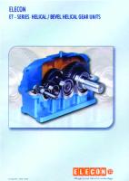
GEARBOX ZF 16S251
RANGE
FAMILY
VARIANT
33G P 6X4 33GG P 6X4 33K T 6X4 RENAULT KERAX
33KK T 6X4
150EQ
33M P 6X6 33MM P 6X6 33N T 6X6 33NN T 6X6
The above information may change in the course of time. Only the "Consult" section of the workshop manuals repertory in standard N° 10320 serves as reference.
32 658
32.6 32.6 . . . .
32.6 . . . . 50 21 014 238
32 658
1
CONTENTS
Generalities . . . . . . . . . . . . . . . . . . . . . . . . . . . . . . . . . . . . . . . . . . . . . . . . . . . A-1 → 5 Technical data. . . . . . . . . . . . . . . . . . . . . . . . . . . . . . . . . . . . . . . . . . . . . . . . . B-1 → 9 Tools . . . . . . . . . . . . . . . . . . . . . . . . . . . . . . . . . . . . . . . . . . . . . . . . . . . . . . . . C-1 → 3
— Description . . . . . . . . . . . . . . . . . . . . . . . . . . . . . . . . . . . . . . . . . . . . . . . . . . . . . . . . . . . . . C1-2 → 13 — How to use the tools . . . . . . . . . . . . . . . . . . . . . . . . . . . . . . . . . . . . . . . . . . . . . . . . . . . . . . C2-1 → 11 — Tools . . . . . . . . . . . . . . . . . . . . . . . . . . . . . . . . . . . . . . . . . . . . . . . . . . . . . . . . . . . . . . . . . . . C3-1 → 9
Disassembly / assembly . . . . . . . . . . . . . . . . . . . . . . . . . . . . . . . . . . . . . . . . D-1 → 9
— Range change . . . . . . . . . . . . . . . . . . . . . . . . . . . . . . . . . . . . . . . . . . . . . . . . . . . . . . . . . . D1-2 → 17 — Gearshift control . . . . . . . . . . . . . . . . . . . . . . . . . . . . . . . . . . . . . . . . . . . . . . . . . . . . . . . . . . D2-1 → 2 — Shift mechanism . . . . . . . . . . . . . . . . . . . . . . . . . . . . . . . . . . . . . . . . . . . . . . . . . . . . . . . . . D3-1 → 22 — Clutch housing . . . . . . . . . . . . . . . . . . . . . . . . . . . . . . . . . . . . . . . . . . . . . . . . . . . . . . . . . . D4-1 → 13 — Main casing . . . . . . . . . . . . . . . . . . . . . . . . . . . . . . . . . . . . . . . . . . . . . . . . . . . . . . . . . . . . . D5-1 → 9 — Shafts . . . . . . . . . . . . . . . . . . . . . . . . . . . . . . . . . . . . . . . . . . . . . . . . . . . . . . . . . . . . . . . . . D6-1 → 11 — Synchromesh . . . . . . . . . . . . . . . . . . . . . . . . . . . . . . . . . . . . . . . . . . . . . . . . . . . . . . . . . . . . D7-1 → 2 — Adjustments . . . . . . . . . . . . . . . . . . . . . . . . . . . . . . . . . . . . . . . . . . . . . . . . . . . . . . . . . . . . . D8-1 → 4 — Checking the pressure . . . . . . . . . . . . . . . . . . . . . . . . . . . . . . . . . . . . . . . . . . . . . . . . . . . . . D9-1 → 1
© RENAULT TRUCKS SA 01/2005 - Imprimé en France - le 02/2005
50 21 014 238
32 658
GENERALITIES
RENAULT TRUCKS
01/2005
A-1
32 658
A-2
Repair manual
16 S 251
NOTE: If clamping fixture 1X56 137 944 is used for dismantling the transmission, remove the reverse gear cover before attaching the clamping fixture. When reassembling the transmission, insert the reverse gear wheel before fitting the shaft set. Then install the reverse idler gear pin.
RENAULT TRUCKS
01/2005
32 658
Important information SAFETY NOTICE
GENERAL INFORMATION
Companies who repair ZF units are responsible for their own work safety.
Read this manual carefully before starting any tests or repair work.
To avoid injury to personnel and damage to products, all safety regulations and legal requirements which apply to repair and maintenance work must be adhered to. Before starting work, mechanics must familiarize themselves with these regulations. Personnel required to carry out repairs on ZF products must receive appropriate training in advance. It is the responsibility of each company to ensure that their repair staff is properly trained.
The following safety instructions appear in this manual:
NOTE Refers to special processes, techniques, data, use of auxiliary equipment, etc.
CAUTION This is used when incorrect, unprofessional working practices could damage the product. ! DANGER This is used when lack of care could lead to personal injury or death.
CAUTION Pictures, drawings and components do not always represent the original object, but are used to illustrate working procedures. Pictures, drawings and components are not to scale and no information about size and weight should be inferred (even within a complete illustration). Always follow the working steps as described in the text.
After completion of repair work and testing, skilled staff must satisfy themselves that the product is functioning correctly. ! THREATS TO THE ENVIRONMENT ! Lubricants and cleaning agents must not be allowed to enter the soil, ground water or sewage system. • Ask your local environment agency for safety information on the relevant products and adhere to their requirements. • Collect used oil in a suitably large container. • Dispose of used oil, dirty filters, lubricants and cleaning agents in accordance with environmental protection guidelines. • When working with lubricants and cleaning agents always refer to the manufacturer’s instructions.
CAUTION The transmission must NOT be hung on the input shaft NOR on the output flange.
RENAULT TRUCKS
01/2005
A-3
32 658
A-4
Instructions for carrying out repairs In any cases of doubt always turn to the the relevant department within ZF After-Sales Services for advice.
After removing the transmission from the vehicle clean thoroughly before opening. Pay particular attention to the corners and angles of housings and covers when cleaning. Parts held on with Loctite can be slightly loosened if warmed with a hot air blower.
GASKETS, LOCKING PLATES Parts which cannot be removed without being damaged must always be replaced with new parts (e.g. gaskets and locking plates).
SHAFT SEALS Always change shaft seals with rough, ripped or hardened packing washers. Seal contact surfaces must be totally clean and in perfect condition.
CLEANING PARTS Remove the old remains of gaskets on all gaskets. Carefully remove burrs or other similar patches of roughness using a oil-stone Lube bores and grooves must be free of anti-corrosion agents and foreign matter, check that they can move without encountering any problems. Carefully cover opened transmissions to prevent the entry of foreign matter..
REWORKING Rework may only be carried out on the seal contact surfaces using plunge-cut grinding, never use an emery cloth. Ensure that there are no traces of grinding traces or rifling from grinding. If rework is needed on distance washers, shims etc. because of clearance settings, ensure that the reworked areas contain no face runout and have the same surface quality.
REUSING PARTS TRANSMISSION ASSEMBLY Parts such as ball or roller bearings, multi-discs, thrust washers etc., must be inspected by a competent person, who should decide whether or not they can be re-used. Replace parts which are damaged or have suffered from excessive wear.
Find a clean site to assemble the transmission. Gaskets are installed without the use of sealing compound or grease. When measuring silicon-coated gaskets, take care not to include the silicon layer in the measurement. During assembly, comply with all adjustment data, checking data and tightening torques in the Repair Manual.
RENAULT TRUCKS
01/2005
32 658
A-5
Instructions for carrying out repairs BEARINGS If the bearings are filled while hot, these should be warmed up accordingly (e.g. in a heating cabinet). The temperature should be approx. 85 °C and may not exceed 120 °C. All bearings must be coated with transmission oil after assembly.
d) Duo shaft seals have two packing washers. The dust-proof packing washer (X) must face outwards. X
e) Fill the gap between the packing washers so it is 60% filled with grease (use a grease e.g. produced by Aral such as Aralub HL2 or by DEA such as Spectron FO 20). f) If possible heat shaft seal bores to between 40 and 50°C (this makes fitting easier). Press the seal shaft with mounting or faceplate onto the relevant installation depth plan.
SEALING If a sealing agent* is to be used for carrying out sealing, comply with the manufacturer’s directions for use. Apply a thin layer of sealing agent to the surfaces and spread evenly. Do not allow sealing to enter oil ducts and bores. On oil-carrying ducts and bores wipe off the sealing agent on the surfaces to be sealed near apertures to ensure that no sealing agent penetrates the oil feeds when the surfaces are sealed.
RETAINING AGENTS Retaining agents* may only be used in places as specified in the parts list. Always comply with manufacturer’s directions for use when using retaining agents (e.g. Loctite). During assembly, comply with all adjustment data, checking data and tightening torques.
SHAFT SEALS a) Apply a light coat of sealing agent on outer edge of shaft seals with “steel surround”. b) Never apply sealing agent to shaft seals with “rubber surround” but apply a thin coat of Vaseline 8420 to the outer edge or wet with a lubricant, e.g. a water-soluble, concentrated washing-up liquid (e.g. Pril, Coin, Palmolive). c) Shaft seals with steel and rubber surrounds should be treated on the outer edge of the rubber surround as described above in section b).
TRANSMISSION OIL After completing repairs, fill the transmission with transmission oil. For the procedure and approved oils, refer to the transmission operating manual and List of Lubricants TE-ML (refer to identification plate) which are available from any ZF After-Sales Service Point. After filling the transmission with oil, tighten the screw plugs at the oil filling point and the oil overflow to the specified torques.
* refer to expendable material
RENAULT TRUCKS
01/2005
A-6
32 658
RENAULT TRUCKS
01/2005
32 658
TECHNICAL DATA
RENAULT TRUCKS
01/2005
B-1
32 658
B-2
Tightening torques Tightening torques for nuts and bolts, extract from ZFN 148 This Standard applies for bolts to DIN 912, DIN 931, DIN 933, DIN 960, DIN 961 and for nuts to DIN 934. This Standard contains data on tightening torques (MA) for bolts in strength categories 8.8, 10.9 and 12.9 and nuts in strength categories 8, 10 and 12.
Surface condition of bolts: heat-treated blackened finish and oiled or galvanized and oiled or galvanized, chrome-plated and oiled. This Standard contains data on tightening torques (MA) for bolts in strength categories 8.8, 10.9 wrench. NOTE Divergent tightening torques are listed separately in the Repair Manual.
Metric coarse pitch thread
Metric coarse pitch thread
Size
Size
Bolt Nut M 4 M 5 M 6
Tightening torque MA (Nm) for 8.8 10.9 8 10 2,8 5,5 9,5
Tightening torque MA (Nm) for 8.8 10.9 8 10
12.9 12
Bolt Nut
12.9 12
4,1 8,1 14
4,8 9,5 16,5
M 8x1 M 9x1 M 10 x 1
24 36 52
36 53 76
43 62 89
M 7 M 8 M 10
15 23 46
23 34 68
28 40 79
M 10 x 1,25 M 12 x 1,25 M 12 x 1,5
49 87 83
72 125 122
84 150 145
M 12 M 14 M 16
79 125 195
115 185 280
135 215 330
M 14 x 1,5 M 16 x 1,5 M 18 x 1,5
135 205 310
200 300 440
235 360 520
M 18 M 20 M 22
280 390 530
390 560 750
460 650 880
M 18 x 2 M 20 x 1,5 M 22 x 1,5
290 430 580
420 620 820
490 720 960
M 24 M 27 M 30
670 1000 1350
960 1400 1900
1100 1650 2250
M 24 x 1,5 M 24 x 2 M 27 x 1,5
760 730 1100
1100 1050 1600
1250 1200 1850
M 27 x 2 M 30 x 1,5 M 30 x 2
1050 1550 1500
1500 2200 2100
1800 2550 2500
RENAULT TRUCKS
01/2005
32 658
B-3
Tightening torques Screw plugs DIN 908, 910 and 7604
Union screws DIN 7643
The screw plug tightening torques MA were determined according to DIN 7604, for screwing into steel, grey cast, and aluminium alloys. The values are based on experience, and are intended as reference values for the designer. The values for the tightening torque MA shall also be used for screw plugs according to DIN 908 and DIN 910, as the thread geometries are almost identical. General rule: Screw/bolt class 5, ZFN 148-1 Screw/bolt material: steel acc. to DIN 7604. Surface condition: as manufactured (without surface protection) and lightly oiled or galvanized, chromated and lightly oiled
The tightening torques MA were determined for screwing into steel, grey cast and aluminium alloys. The values are based on experience and are intended as reference values for the designer. General rule: screw/bolt class 5, ZFN 148-1 Material 9SMnPb28K acc. to DIN 1651 Surface conditions: as manufactured (without surface protection) and lightly oiled or galvanized, chromated and lightly oiled
Screw plugs (DIN 908, 910, 7604) Dimensions
M 8x1 M 10 x 1 M 12 x 1.5 M 14 x 1.5 M 16 x 1.5 M 18 x 1.5 M 20 x 1.5 M 22 x 1.5 M 24 x 1.5 M 26 x 1.5 M 27 x 2 M 30 x 1.5 M 30 x 2 M 33 x 2 M 36 x 1.5 M 38 x 1.5 M 42 x 1.5 M 42 x 2 M 45 x 1.5 M 45 x 2 M 48 x 1.5 M 48 x 2 M 52 x 1.5 M 60 x 2 M 64 x 2
Tightening torque screwed into steel/grey cast Al alloy 20 25 / 30* 35 35 40 50 55 60 / 80* 70 80 / 105* 80 100 / 130* 95 120 130 140 150 145 160 150 170 160 180 195 205
* DIN 7604 Form C
RENAULT TRUCKS
Union screws (DIN7643)
01/2005
10 15 / 20* 25 25 30 35 45 50 / 65* 60 70 / 90* 70 90 / 130* 85 110 115 120 130 125 140 130 145 135 150 165 175
Pipe outer diameter
Thread
Tighteningtorque MA in Nm
4-5
M8x1
30
6
M 10 x 1
35
8
M 12 x 1.5
40
10
M 14 x 1.5
40
12
M 16 x 1.5
45
15
M 18 x 1.5
50
18
M 22 x 1.5
60
22
M 26 x 1.5
90
28
M 30 x 1.5
130
35
M 38 x 1.5
140
32 658
B-4
Adjustment data
16 S 251
Description
Tolerance
Measuring device
Remarks
01. Axial play on layshaft
0.0 - 0.10 mm
Depth gauge or dial gauge
Centre bearings (zero play) and measure play. Adjust using shims on roller bearing outer race on output end.
02. Combined axial play of mainshaft and input shaft
0.0 - 0.10 mm
Depth gauge or dial gauge
Centre bearings (zero play) and measure play. Adjust using shims on roller bearing outer race on input shaft.
03. Axial play / prestress of split ring on input shaft and mainshaft (only in older version)
- 0.05 to + 0.05 mm
Micrometer or feeler gauge
Always use correct tool.
Depth gauge and/or drift 1X56 137 124
Measure depth of insertion between outside of cover and face of shaft seal. If drift is used with ring, depth is automatically given (must be flat).
12.5 + 1.0 mm 04. Insertion depth for shaft seal in output flange cover
05. Axial play on ball bearing in cover (range-change)
0 - 0.10 mm
Depth gauge/sliding caliper
Adjust using appropriate shims in cover.
06. Axial play on helical gear on input shaft
Min. 0.20 mm
Depth gauge or feeler gauge
Not adjustable. Measure as check only.
07. Axial play on helical gears on mainshaft
Min. 0.20 mm
Depth gauge or feeler gauge
Not adjustable. Measure as check only.
08. Axial play on 4th-speed helical gear
Min. 0.05 mm
Depth gauge or feeler gauge
Not adjustable. Measure as check only.
09. Axial play on circlips on layshaft and mainshaft
0 - 0.05 mm
Micrometer or feeler gauge
Use appropriate circlip.
10. Axial play of reverse idler gear
0.4 - 1.10 mm
Feeler gauge
Not adjustable. Measure as check only.
11. Permitted axial play on planet gears in planet carrier
0.4 to 1.30 mm
Feeler gauge
Tolerance includes permitted wear on thrust washers. If wear limit exceeded exchange thrust washers
RENAULT TRUCKS
01/2005
32 658
16 S 251
B-5
Adjustment data
Description
Tolerance
12. Wear limit for synchronizer ring and clutch body, measured between flat surfaces of ring and body with cones firmly nested together. 4-gear section and splitter Range-change
Measuring device
Remarks
Feeler gauge
Exchange synchronizer ring and/or clutch body if dimension too small
0.80 mm 1.20 mm
13. Wear limit for 1st/2nd gear synchronizer parts, measured between outer ring and clutch disc, measured with cones nested firmly together and force F = 50 N applied on the outer ring.
1.5 mm
Feeler gauge
Exchange intermediate ring and/or outer ring and inner ring if wear limit is excluded.
14. Max. permitted play on fulcrum pads in sliding sleeves
0.6 - 1.2 mm
Feeler gauge
Exchange if play is excessive
15. Adjusting mainshaft and determining thickness of ring and shim
+ 0.07 to - 0.08 mm (Shim) 4.6 -0.4 mm (Ring)
Depth gauge
Measure and determine thickness of shim first. Then, measure and select ring.
16. Temperature for shrinkfitting helical gears onto layshaft
160 - 180°C
Temperature probe
Gears and shaft seats must be free of oil and grease during assembly
17. Tightening torque for breather
10 Nm
Torque wrench
18. Tightening torque for M12 x 1.5 screws in housing
30 Nm
Torque wrench
Use new seal rings
19. Tightening torque of union screws for plastic pipes
35 Nm
Torque wrench
Use new seal rings
RENAULT TRUCKS
01/2005
32 658
B-6
Adjustment data
16 S 251
Description
Tolerance
Measuring device
Remarks
20. Tightening torque for detent plungers
50 Nm
Torque wrench
Use new seal rings
21. Tightening torque for pressure switch/impulse sensor
50 Nm
Torque wrench
Use new seal rings
22. Tightening torque of M12 bolts for output flange
120 Nm
Torque wrench
Fit new retaining plate. Use Loctite No. 262.
23. Tightening torque for shift 4-gear section: 50 Nm fork grub screws Splitter: 60 Nm
Torque wrench
24. Tightening torque "M24 x 1,5 magnetic screw"
Torque wrench
Clean magnet and fit new seal ring
Torque wrench
Use new locking nut
60 Nm
150 Nm 25. Tightening torque for locking nuts on rangechange and splitter pistons 26. Tightening torque for hex bolts between clutch housing and mid-housing
50 Nm
Torque wrench
27. Tightening torque for hex bolts between mid-housing and GP housing
50 Nm
Torque wrench
Use new seal rings
28. Tightening torque for M18 x 1.5 screw plugs on housing
35 Nm
Torque wrench
Use new seal rings
29. Tightening torque for M22 x 1.5 screw plugs on housing
50 Nm
Torque wrench
Use new seal rings
30. Tightening torque for M24 x 1.5 screw plugs on housing
60 Nm
Torque wrench
Use new seal rings
31. Heating temperature for ring gear
60°C
Temperature probe
Do not exceed temperature
32. Temperature of synchronizer hub, clutch body, bushes and counting disc
120°C
Temperature probe
Do not exceed temperature
RENAULT TRUCKS
01/2005
32 658
16 S 251
B-7
Adjustment data
Description
Tolerance
Measuring device
Remarks
33. Temperature of output flange
max. 70°C
Temperature probe
Do not exceed temperature
34. Temperature of input shaft 100°C roller bearing
Temperature probe
Do not exceed temperature
35. Temperature of 4th-speed helical gear with needle cages on mainshaft
120°C
Temperature probe
Do not exceed temperature
36. Rolling-in torque for injection pipe
5 -6 Nm
Torque wrench
Rolling-in tool 1X56 155 653
37. Lifting device for input shaft/ mainshaft/ layshaft
85 Nm
Torque wrench
DANGER Fit lifting device carefully
38. Tightening torque for pivot bolts on shift fork
250 Nm
Torque wrench
Use Loctite No. 241
39. Tightening torque for M8 hex bolts on shift cover
23 Nm
Torque wrench
40. Tightening torque for M10 hex bolts on shift lever
49 Nm
Torque wrench
41. Tightening torque for M8 hex bolts on shift housing cover (with detent piece)
23 Nm
Torque wrench
42. Tightening torque for M8 hex bolts on cutoff valve
23 Nm
Torque wrench
43. Tightening torque hollow screws/Servoshift
20 Nm
Torque wrench
44. Tightening torque hex screws M8x80/Servoshift
23 Nm
Torque wrench
45. Tightening torque screw plugs M22x1,5 shift turret/Servoshift
60 Nm
Torque wrench
RENAULT TRUCKS
01/2005
Use new sealing rings.
Use new sealing rings.
32 658
B-8
Adjustment data
Description
16 S 251
Tolerance
Measuring device
46. Tightening torque hex 23 Nm screws M8x30 shift turret/ Servoshift
Torque wrench
47. Tightening torque switch shift turret/ Servoshift
50 Nm
Torque wrench
48. Tightening torque hex scr- 23 Nm ews M8x65 cut off valve
Torque wrench
49. Tightening torque hex 49 Nm screws M10x65 shift lever
Torque wrench
50. Permitted axial play on mainshaft/planetary drive
Measuring bush 1X56 138 158
± 0.05 mm
Remarks
Use new sealing ring.
Adjust using appropriate shim
RENAULT TRUCKS
01/2005
32 658
B-9
16 S 251
Table of springs
Part number
Installation point
RENAULT TRUCKS
No. of windings
Wire diam. in mm
Spring diam. Untensioned in mm length in mm
77 01 007 805
synchr./planet carrier
18.5
1.25
6.25
34.2
50 00 255 277
synchr./planet carrier
35.5
0.70
3.2
34.7
50 00 242 857
synchronization drive shaft and main shaft
12.5
1.40
6.65
23.7
50 00 240 495
blocking pin interlock
13.5
1.60
9.8
36.0
50 01 848 893
shift system/Servoshift
7.5
1.80
26.1
50.5
50 00 456 234
shift system/Servoshift
6.5
2.00
14.4
23.4
50 00 815 358
R-gear interlock/ selector housing
5.5
2.25
14.8
21.6
50 01 850 732
shift system/Servoshift
5.1
2.10
39.0
70.0
50 00 272 944
selector housing
8.0
2.00
27.0
77.7
RENAULT TRUCKS
01/2005
B-10
32 658
RENAULT TRUCKS
01/2005
32 658
TOOLS
RENAULT TRUCKS
01/2005
C1-1
32 658
C1-2
Description Generalities RENAULT TRUCKS divide tools into three categories: – General-purpose tools: proprietary tools. • 50 00 26 .... reference number (possibility of purchasing through the RENAULT TRUCKS Spare Parts department). • 4-figure reference number (tools classified by RENAULT TRUCKS but available from the supplier). – Special tools: specifically created tools distributed by the RENAULT TRUCKS Spare Parts Department. – Locally manufactured tools: these tools are classified differently according to their degree of sophistication: • 4-figure reference number (represented by a drawing): tools that are simple to make without need for special qualification. • 50 00 26 .... reference number (possibility of purchasing through the RENAULT TRUCKS Spare Parts department): a certain amount of skill is needed to make these tools. Three levels (or echelons) determine their assignment: – Level 1: tools for servicing, maintenance and minor tasks. – Level 2: tools for major repairs. – Level 3: tools for refurbishment.
Proprietary tools mentioned in this manual do not appear in the tools list. These tools are identified in the standard tools manual (MO) by a 4-figure number.
RENAULT TRUCKS
01/2005
32 658
C1-3
Equivalents table The standardization of tools leads us to have to extend RENAULT TRUCKS tools to major units. An equivalence table serves to determine the RENAULT TRUCKS tools that are to replace the tools stipulated in the document.
The use of RENAULT TRUCKS tools requires the compulsory replacement of all bearings.
ZF part N°
RENAULT TRUCKS part N°
1 x 20 155 653
50 00 26 2460
1 x 56 103 766
50 00 26 3016 + 50 00 26 2363
1 x 56 119 916
50 00 26 2363 + 50 00 26 3016
1 x 56 119 916
50 00 26 2351 + 50 00 26 3016
1 x 56 122 303
Hydraulic press
1 x 56 122 304
50 00 26 0827 + Hydraulic press
1 x 56 122 304
50 00 26 0819 + Hydraulic press
1 x 56 122 310
50 00 26 0819 + Hydraulic press
1 x 56 122 314
50 00 26 0845
1 x 56 136 564
3241
1 x 56 136 710
50 00 26 0827 + Hydraulic press
1 x 56 136 722
Hydraulic press
1 x 56 136 743
50 00 26 0827 + Hydraulic press
1 x 56 136 756
50 00 26 0827 + Hydraulic press
1 x 56 137 122
2388 + 3253
1 x 56 137 124
50 00 26 2351 + 50 00 26 3016
1 x 56 137 200
2388
1 x 56 137 287
Bolt 16 x 150 - Length 45 mm
1 x 56 137 579
2384
1 x 56 137 651
50 00 26 2456
1 x 56 137 675
Not necessary
1 x 56 137 676
Tube + Screwdriver
1 x 56 137 835
50 00 26 2379
1 x 56 137 917
2399B
1 x 56 137 918
2388 + 3253
1 x 56 137 921
2388 + 3253
1 x 56 137 933
2388 + 3253
1 x 56 137 953
Not necessary
1 x 56 137 991
50 00 26 2351 + 50 00 26 3016
1 x 56 138 063
2454
RENAULT TRUCKS
01/2005
32 658
C1-4
ZF part N°
RENAULT TRUCKS part N°
1 x 56 138 064
Adhesive tape type protection
1 x 56 138 079
50 00 26 2735
1 x 56 138 109
50 00 26 2363 + 50 00 26 3016
1 x 56 138 158
50 00 26 2555
-
50 00 26 0843
-
50 00 26 1000
-
50 00 26 2203
-
50 00 26 2381
-
50 00 26 2413
-
50 00 26 2513
-
50 00 26 9134
-
2399A
RENAULT TRUCKS
01/2005
32 658
C1-5
LIST OF TOOLS General-purpose tools
Illustration
RENAULT TRUCKS
RENAULT TRUCKS Ref.
Designation
5000262351
Manufacturer reference
Manufacturer code
Level
Qty
Set of pushers
1
1
5000260827
Puller
2
1
5000260819
Unsticker
2
1
5000260845
Puller
2
1
5000260843
Puller
1
1
5000261000
Universal stand
2
1
5000262856
Puller
1
1
01/2005
32 658
C1-6
5000260833
Puller
2
RENAULT TRUCKS
1
01/2005
32 658
C1-7
Special Tools
Illustration
RENAULT TRUCKS
RENAULT TRUCKS Ref.
Designation
5000262460
Manufacturer reference
Manufacturer code
Level
Qty
Swaging tool
2
1
5000263016
Handle
1
1
5000262363
Set of pushers
2
1
5000262456
Rivet snap
2
1
5000262379
Guard
2
1
5000262735
Adjusting tool
2
1
5000262555
Tester
2
1
01/2005
32 658
C1-8
5000262203
Fitting
2
1
5000262381
Extension
1
1
5000262413
Fitting
2
1
5000269134
Holding wrench
1
1
RENAULT TRUCKS
01/2005
32 658
C1-9
Locally manufactured tools
Illustration
RENAULT TRUCKS
RENAULT TRUCKS Ref.
Designation
Manufacturer reference
Manufacturer code
Level
Qty
3241
Hook
1
2
2388
Hook
2
1
3253
Hook
2
1
2384
Retainer
2
1
2399
Positioner B
2
1
2454
Pusher
1
1
2513
Tube
2
1
01/2005
32 658
C1-10
2399
Positioner A
2
RENAULT TRUCKS
1
01/2005
32 658
RENAULT TRUCKS
01/2005
C1-11
C1-12
32 658
RENAULT TRUCKS
01/2005
32 658
RENAULT TRUCKS
01/2005
C1-13
C1-14
32 658
RENAULT TRUCKS
01/2005
32 658 How to use the tools Disassembly Mount on stand 1000
Hold the output flange using tool 9134
Remove the output flange using tools 0843 and 2381
RENAULT TRUCKS
01/2005
C2-1
C2-2
32 658
Extract the output shaft bearing using tool 2856
Remove the cylindrical dowels using tool 2454
Remove the output end cover using a strap.
Remove the clutch casing using tool 3241
RENAULT TRUCKS
01/2005
32 658 Immobilize the splitter control shaft using tool 2384
Mount tool 2388 for removing the main shaft.
Remove the main shaft and the countershaft using tools 3253 and 2388
Remove the input shaft bearing using tool 0819
RENAULT TRUCKS
01/2005
C2-3
C2-4
32 658
Remove the main shaft rear bearing outer ring using tools 3016 and 2363
Remove the countershaft rear bearing outer ring.
Extract the main shaft front bearing using tool 0827
Extract the reverse pinion using tool 0833
RENAULT TRUCKS
01/2005
32 658 Extract the 1st speed pinion using tool 0833
Extract the 2nd speed pinion.
Extract the 3rd speed pinion.
Extract the last two main shaft pinions and synchronizer using tool 2513
RENAULT TRUCKS
01/2005
C2-5
C2-6
32 658
Remove the countershaft pinion and front bearing.
Extract the countershaft output end taper roller bearing using tool 0819
RENAULT TRUCKS
01/2005
32 658 Assembly / Adjustment Fit the countershaft pinions using tool 2513
Fit the countershaft front bearing using tool 2513
Fit the countershaft rear bearing using tool 2513
Fit the main shaft pinions, synchronizer and bearing using tool 2513
RENAULT TRUCKS
01/2005
C2-7
C2-8
32 658
Fit the main shaft synchronizer and last pinion using tool 2513
Fit the input shaft oil retainer disc using tools 3016 and 2363
Fit the input shaft bearing and pinion using tool 2513
Fit the main shaft injection pipe using tool 2379
RENAULT TRUCKS
01/2005
32 658 Fit the countershaft rear bearing outer ring using tools 3016 and 2363
Fit the main shaft rear bearing outer ring using tools 3016 and 2363
Fit the main shaft and the countershaft using tools 3253 and 2388
Fit the seal ring to the stop guide using tools 3016 and 2363
RENAULT TRUCKS
01/2005
C2-9
C2-10
32 658
Fit the lip seal to the control cover using tools 3016 and 2363
Fit the bearing bushing to the control cover using tools 3016 and 2363
Fit the lip seal, then the scraper, to the control cover using tools 3016 and 2351
Fit the O-ring to the control casing using tools 3016 and 2363
RENAULT TRUCKS
01/2005
32 658 Fit the output shaft seal ring using tools 3016 and 2363
Adjust the clutch operating fork using tool 2735
Adjust the planetary gear train using tool 2555
RENAULT TRUCKS
01/2005
C2-11
C2-12
32 658
RENAULT TRUCKS
01/2005
32 658
C3-1
Tools
Special tools
Fig. no.
16 S 251
Special tools
Order no.
Application
1X20 155 653
Remarks
1
Chapter 5.3
1
Chapter 4.1
1
Chapter 3.1 3.2
1
Chapter 6
1
Chapter 6 7 8
Pipe roller for spray tube
1
1X56 103 766 Adapter for shaft seal in connection plate
2
1X56 119 916 Adapter for gear shift housing
3
1X56 122 303 Adapter for bearing inner ring / input shaft
4
1X56 122 304 Rollex basic tool for Adapter
5
RENAULT TRUCKS
Qty.
01/2005
32 658
C3-2
16 S 251
Fig. no.
Special tools
Special tools
Order no.
Application
1X56 122 310
6
1
Chapter 1.3
2
Chapter 4.3
1
Chapter 8
1
Chapter 6
Grip for bearing inner ring / layshaft
1X56 136 722
10
Chapter 6
Hook for clutch housing
1X56 136 710
9
1
Rillex extractor for ball bearing / output shaft
1X56 136 564
8
Remarks
Rollex bush for bearing inner ring / input shaft
1X56 122 314
7
Qty.
Grip for bearing inner ring / input shaft
RENAULT TRUCKS
01/2005
32 658
C3-3
Special tools
Fig. no.
16 S 251
Special tools
Order no.
Application
1X56 136 743
Remarks
1
Chapter 7
1
Chapter 8
1
Chapter 5.3
1
Chapter 1.3
1
Chapter 7
Grip for bearing inner ring / main shaft
11
1X56 136 756 Grip for bearing inner ring / layshaft
12
1X56 137 122 Lifting device for shaft package
13
1X56 137 124 Adapter for shaft seal / output shaft
14
1X56 137 200 Lifting rod for main shaft
1X5
15
6 13 7 20 0
RENAULT TRUCKS
Qty.
01/2005
32 658
C3-4
16 S 251
Fig. no.
Special tools
Special tools
Order no.
Application
Qty.
1X56 137 287
16
Chapter 1.5 1.6 5.1 5.5
1
Chapter 1.2
1
Chapter 5.3
1
Chapter 10.1
Holding fixture for shaft package
1X56 137 676
20
1
Adapter for locking plate / output flange
1X56 137 675
19
Chapter 5.3
Fixing device for panel stop
1X56 137 651
18
1
Fixing screw for removal and installation of shafts
1X56 137 579
17
Remarks
Adapter for split ring / main shaft
RENAULT TRUCKS
01/2005
32 658
C3-5
Special tools
Fig. no.
16 S 251
Special tools
Order no.
Application
1X56 137 835
Remarks
1
Chapter 5.4
1
Chapter 5.2 11.1
1
Chapter 5.3
1
Chapter 5.3
1
Chapter 5.3
Adapter for installation of spray tube / main shaft
21
1X56 137 917 Support plate for adjustment of piston and compressed-air test
22
1X56 137 918 Fixing device for removal and installation of shafts
23
1X56 137 921 Centering ring for removal and installation of shafts
24
1X56 137 933 Shim for removal and installation of shafts
25
RENAULT TRUCKS
Qty.
01/2005
32 658
C3-6
16 S 251
Fig. no.
Special tools
Special tools
Order no.
Application
1X56 137 953
Qty.
Remarks
1
Chapter 5.3
1
Chapter 5.3
1
Chapter 4.3
1
Chapter 4.1
1
Chapter 5.2
Bolt for installation and dismantling of shafts together with 1X56 137 675
26
1X56 137 991 Distance ring for shaft sealing ring / output, together with 1X56 137 124
27
1X56 136 445
1X56 138 063 Extraction tool for cylinder pins on clutch housing that are difficult to reach
28
1X56 138 064 Protective sleeve for connection plate / input shaft
29
1X56 138 064 004344
1X56 138 079 Centering aid for selector rail / splitter group fixation
30 009526
RENAULT TRUCKS
01/2005
32 658
C3-7
Special tools
Fig. no.
16 S 251
Special tools
Order no.
Application
1X56 138 109
Remarks
1
Chapter 6
1
Chapter 10.4
Adaptor for oil baffle plate / input shaft
31
1X56 138 158 Measuring bush for adjustment or measurement main shaft/planetary drive
32
RENAULT TRUCKS
Qty.
01/2005
RENAULT TRUCKS
1X56 137 921
1X56 137 122
1X56 122 304
1X56 137 918
1X56 136 756
1X56 137 287
1X56 136 710
1X56 137 579
1X56 137 675
1X56 137 953
1X56 137 651
1X56 137 991
1X56 137 124
16 S 251
1X56 137 933
1X56 122 303
1X56 136 564
C3-8
32 658
Spezialwerkzeuge
01/2005
RENAULT TRUCKS
01/2005 009526
1X56 138 109
1X56 138 079
1X56 137 676
1X56 137 917
1X56 137 835
1X56 138 158
1X56 136 722
1X56 137 200
1X56 122 314
1X56 119 916
200
1X56 138 064
1X56 136 743
137
1X20 155 653
1X56 138 063
1X56
1X56 103 766
1X56 122 310
32 658 C3-9
Spezialwerkzeuge 16 S 251
C3-10
32 658
RENAULT TRUCKS
01/2005
32 658
DISASSEMBLY / ASSEMBLY
RENAULT TRUCKS
01/2005
D1-1
32 658
D1-2
Range change
16 S 251 1
Removing components / range-change
1.1
Plastic pipes
Range-change / Plastic pipes
2 5
Removal NOTE Label plastic pipes before removing to ensure correct re-assembly. 1
Unscrew union screws (1 and 2) from rangechange cylinder (3) and cutoff valve (4). Loosen pipe clip (5) on housing and remove complete together with plastic pipes (6).
3
2 6
1
4 1
011373
Mounting 1
Using union screws and new seal rings, screw plastic pipes (6) to cylinder (3) and shut-off valve (4) as marked. Tightening torque = 38 Nm.
2
Strap up plastic pipes an fix cable strap (5) together with plastic pipes to housing.
RENAULT TRUCKS
01/2005
32 658
D1-3
Range-change / Output flange 1.2
16 S 251
Output flange Removal
1
Lever off retaining plate (1) from bolts (2).
2
Secure output flange to prevent it from turning.
3
Unscrew hex bolts (2) and remove clamping disc (3).
4
Place adapter onto planet carrier and remove output flange (4) using 2- or 3-leg puller.
5
Remove O-ring (5).
2
1
3 5 4
011374
Mounting 1
Lightly oil shaft seal in cover.
! DANGER Always wear protective gloves when handling heated output flange.
4 2 3
2
Heat output flange (1) to max. 70° C.
3
Push output flange flush onto planet carrier shaft.
4
Pull on output flange until flush using disc (2) and two standard M12x75 hex bolts.
5
Remove disc and bolts.
6
Lightly oil new O-ring (3) and insert into gap between output flange and planet carrier shaft.
7
Insert disc (2) into output flange and attach to planet carrier using locking screws. Tightening torque = 120 Nm. If required, use flange holder to prevent flange from turning. Insert locking screws with Loctite 262.
8
Using special tool 1X56 137 651, drive new retaining plate (4) flush onto bolt heads.
RENAULT TRUCKS
01/2005
1
011375
32 658
D1-4
16 S 251 1.3
Range-change / Cover
Cover 1
Removal 1
2
3 4
Unscrew hex bolts from cover (1) and remove together with gasket (2).
2
Unscrew hex bolts and remove cover (3) together with gasket (4), shaft seal (5) and shim (6).
3
Use Rillex extractor 1X56 122 314 to remove ball bearing (7) from output shaft.
4
Using plastic drift, drive out shaft seal (5) from cover.
5
6 7
011376
Mounting Measuring ball bearing axial play (nominal: 0 to 0.1 mm) 1
5 2
Fit new gasket (1) onto new cover (2) and measure insertion depth of cover together with gasket, e.g. 23.40 mm.
2
Measure extraction depth bearing seat depth of housing (without gasket), e.g. 7.00 mm.
3
Measure width of ball bearing (3), e.g. 30.00 mm.
1 4 3
Example 23.40 mm insertion depth - cover + 7.00 mm insertion depth - housing 30.40 mm – 30.00 mm width of ball bearing = 0.40 mm axial play without shim
011377
i.e. a 0.3 to 0.4 mm shim (4) is required to give axial play of 0 to 0.1 mm. ! DANGER Always wear protective gloves when handling heated cover.
4
Heat cover (2) to approx. 60° C and insert correct shim (4) and ball bearing (3).
5
Drive in shaft seal (5) using special tool 1X56 137 124.
RENAULT TRUCKS
01/2005
32 658
D1-5
Range-change / Cover NOTE Only use special tool with 12.5 mm wide ring. Installation dimension = 12.5 + 1.0 mm between edge of cover and shaft seal. Thinly coat outside of shaft seal with sealing compound. Lubricate outside of shaft seal with rubber surround using soap wash.
16 S 251
6
6 Fit cover (2) with new gasket (1) and tighten using hex bolts and washers. Tightening torque = 49 Nm. 7 Fit cover (6) with new gasket. Tightening torque = 79 Nm.
2 1
011378
RENAULT TRUCKS
01/2005
32 658
D1-6
16 S 251 1.4
Range-change / Way valve
5/2-way valve Removal
1
Unscrew 5/2-way valve (1) from centre housing.
2
Remove O-rings (2). NOTE Do not dismantle 5/2-way valve since it is a complete part.
2
1
011379
Mounting 1
Insert new O-ring (2) into 5/2-way valve (1).
2
Screw 5/2-way valve (1) onto centre housing. Tightening torque = 9.5 Nm.
RENAULT TRUCKS
01/2005
32 658
D1-7
Range-change / Shift cylinder 1.5
16 S 251
Shift cylinder for range-change Removal
1
1
Unscrew hex bolts, loosen cylinder (1) from range-change housing and remove from piston (2).
2
Remove O-rings (3 and 4) from cylinder.
3
Remove detent plunger (5). Screw fixing device 1X56 137 579 into threaded bore and position fixing element on shift rail (6). Tighten fixing device. Tightening torque = 50 Nm.
4
Unscrew locking nut (7) from piston (2).
5
Remove piston together with guide ring (8).
6
Remove seal rings (11).
7
Remove guide ring from piston.
8
Pull out flange packing (10) from range-change housing.
4 11 7 2
5
11 10
8 3
6
011380
RENAULT TRUCKS
01/2005
32 658
D1-8
16 S 251
Range-change / Shift cylinder
Mounting 1 1
2
3
Coat new flange packing (10) with spirit, slide over shift rail (6) and, using soft drift, drive in until flush.
4 11 7 2
Place sealing ring (11), piston (2) together with guide ring (8) and sealing ring (11) on shift rail (6).
11 10
8 3
Tighten new locking nut (7) once range-change is fitted. Tightening torque = 150 Nm. NOTE Installation of range-change cylinder is only possible once range-change has been subassembled on centre housing. Thread must be absolutely free of oil and grease.
4
Grease new O-rings (4 and 3) and insert into correct annular grooves (in cylinder and housing).
5
Carefully slide cylinder (1) over piston together with guide ring and piston gasket. Fix cylinder using two hex bolts.
6
011381
NOTE Align the compressed air bores.
RENAULT TRUCKS
01/2005
32 658
D1-9
Range-change / Housing 1.6
16 S 251
Housing/range-change 1
Removal 1
12
Remove mechanical speedometer or impulse sensor (15).
2
Remove pivot bolts (1) for shift fork (2).
3
Remove fixing device 1X56 137 579.
4
Unscrew hex bolts from range-change housing (3).
! DANGER Planet gear train is not secured on mainshaft. Secure this to prevent from falling.
5
Separate range-change housing (3) from centre housing (5) without tilting and remove. Use pins to ensure correct position (4).
6
Remove shift fork (2) together with fulcrum pads (6).
7
Remove intermediate plate (7) together with gaskets (8).
8
Remove switch (9) together with seal ring and pin (10). Other version (13 and 14) also possible.
9
Pull out shift rail (11) from centre housing.
10
Remove injection pipe (12).
4 4 15 4
3
6
1
2
8 7
8
5
13 14
11
9 10 011382
RENAULT TRUCKS
01/2005
32 658
D1-10
16 S 251
Range-change / Housing
Mounting 1
Place intermediate plate (1) onto planet carrier/clutch body (2).
2
Insert shift fork (3) and fulcrum pads (4) into sliding sleeve (5).
3
Place new gasket (6) onto intermediate plate (1) and position.
4
Insert shift rail (11) from inside of housing and position roughly.
5
Insert injection pipe (20) into housing.
6
Place housing (7) onto intermediate plate (1), fit gasket and position. Check radial position of shift fork and engage.
7
With the range change group installed, coat pivot bolt threads (10) with Loctite No. 241, place spring disks and screw in. Tightening torque = 250 Nm
10 21 22 8 W1 W11 9
7 6
1
20
10
4
NOTE When using a new housing (7), drive in ball (8) in accordance with selector pattern I or II.
3
5 2 011383
RENAULT TRUCKS
01/2005
32 658
D1-11
Range-change / Housing
16 S 251
Installing complete range-change NOTE Main shaft / planetary drive must be measured prior to installation of the range-change group; see Section 10.4. 1
Fit new gasket (1) onto centre housing (2). 1
NOTE There must be 3 cylindrical pins in centre housing. 2
2
Fit 2 hex bolts to range-change housing to allow range-change to be suspended from a rope and positioned horizontally against centre housing.
CAUTION Secure hex bolts with nuts. Ensure rope is firmly secured. Hint: Use threaded pins on centre housing to simplify positioning of range-change. 3
Push range-change against centre housing (2). Turn output flange to bring planet gear train and mainshaft teeth into mesh if necessary.
4
Remove hex bolts and rope when range-change is held against centre housing.
5
Slide range-change (3) parallel to centre housing and bolt together. Tightening torque = 49 Nm.
6
Switch piston to end position (high or low group).
RENAULT TRUCKS
01/2005
3 2
011384
32 658
D1-12
16 S 251 1.7
Range-change / Planetary drive
Planetary drive with synchronization
2
Dismantling 1 NOTE Prior to removing the planetary drive, make sure it cannot drop. 1
Remove entire planetary drive together with synchronization from main shaft.
4 5
6 7
8 9 10
1.7.1 Synchronization 11
12
! DANGER Pressure pieces are in a state of spring tension. Safeguard these against disengagement.
1
Place pressure piece on planet carrier. Position two or three-arm puller under sliding sleeve (1) and extract together with clutch body (2). The pressure pieces (4) and pressure springs (5) fixed by sliding sleeve may be intercepted in a “jumping sheet”.
2
Remove synchronizer ring (6).
3
Disengage circlip (7).
4
Place pressure piece on planet carrier and remove sychronizer (8) by positioning two or threearm puller under sychronizer and extracting it.
5
Remove synchronizer (9), clutch body (10) and clutch disc (11) from planet carrier.
6
Disengage circlip (12) on clutch body.
011385
RENAULT TRUCKS
01/2005
32 658
D1-13
Range-change / Planetary drive
16 S 251
Mounting 1
9 10
Check wear limit of synchronizer parts, see Section 9.
2
Place clutch disc (11) on planet carrier.
3
Insert snap-ring (12) in clutch body (10) and slide onto planet carrier.
4
Place synchronizer ring (9) on planet carrier.
12
11
2
! DANGER Always wear protective gloves when handling heated synchronizer hub.
5
Heat synchronizer hub (8) to approx. 120°C and push on until firmly seated. Ensure long hub side faces planet carrier. Synchronizer ring lugs must engage into recesses in the synchronizer hub.
6
Enter circlip (7) in groove with an end float of between 0 and 0.1 mm. Circlips are available in 0.1 mm thicknesses (0.1, 0.2, 0.3 mm etc.).
7
Place sliding sleeve (1) onto synchronizer hub (8) with collar side facing towards output end. NOTE Recesses in sliding sleeve must be aligned with recesses in synchronizer hub.
8
Insert new compression springs (5) and pressure pieces (4) into synchronizer hub (8) and, using suitable tool, insert into sliding sleeve (1).
9
Place synchronizer ring (6) onto synchronizer hub (8). NOTE Synchronizer ring lugs (6) must engage into recesses in the synchronizer hub (3).
! DANGER Always wear protective gloves when handling heated clutch body.
10
Heat clutch body (2) to approx. 120°C and push flush onto planet carrier.
11
Press sunchronizer ring (6) against synchronizer hub (2) and bring sliding sleeve (1) into central position. You will be able to clearly hear the pressure pieces snapping in.
RENAULT TRUCKS
01/2005
1 4 5
6 7
8
011386
32 658
D1-14
16 S 251
Range-change / Planetary drive
1.7.2 Ring gear Removal 1
Detach safety wire (4) from annular groove in ring gear.
2
Attach circlip (7), from Section 1.7.1, onto ring gear carrier. Place pressure piece on planet carrier and fit using two leg or three leg puller underneath circlip. Take off ring gear carrier (2).
3
Remove ring gear (1) together with thrust ring (5) from planet carrier.
4
Remove thrust ring (5) from ring gear.
5
Remove spacer ring (3) from planet carrier.
3
4 2 5 1
011387
Mounting 1
Place thrust ring (5) on support in ring gear (1). 3
! DANGER Always wear protective gloves when handling heated ring gear.
2
Heat ring gear to 60°C and place planet carrier in ring gear by turning planet gear achieve meshing.
3
Slide spacer ring (3) onto the planet carrier (6).
4
Drive ring gear carrier (2) into the ring gear (1) to bring about axial alignment.
5
Snap locking wire (4) into ring groove of ring gear and bring about snug fit around entire circumference.
4 5 1
2
6
0113 011388
RENAULT TRUCKS
01/2005
32 658
D1-15
Range-change / Planetary drive
16 S 251
1.7.3 Planet carrier 4 7
Removal 1
Drive dowels (1) fully into planet pin (2).
2
Using plastic drift, drive out planet gear pin form planet carrier (3) towards “input”.
3
Remove planet gear (4) from planet carrier together with bush (5).
4
Remove shims (6) and cylinder rolls (7) from planet gear.
5
Drive dowels (1) from planet pin. Repeat steps 1) to 5) for remaining planet gears.
6
7
6
5
1
3 2
011389
6
Remove thrust washer (8) from planet carrier.
7
Remove snap-rings (9 and 10) and lift off with cover (11).
8
Remove axial ball bearing (13) and 4 plate springs (12).
12 13 10 8
11
9
0113 011390
RENAULT TRUCKS
01/2005
32 658
D1-16
16 S 251 1
Range-change / Planetary drive
Insert 4 plate spring (11) and axial ball bearing (10) into planet carrier. NOTE For teh arrangement of the 4 plate springs (11) see Fig. 012317.
2
11 10
Insert cover (12) and snap-rings (13 and 14). 13
NOTE For propper installation of the snap-ring (13) see Fig. 012318. 3
12
14 15
Add thrust washer (15).
011393
012317
Output
Input
012318
RENAULT TRUCKS
01/2005
32 658
D1-17
Range-change / Planetary drive
16 S 251
NOTE Always exchange planet gears as complete sets.
2a 5
4
Coat faces of planet gears and cylinder roller raceways with oil.
5
Stand planet gear pin (1) so that collar faces downwards.
6
4 3 5 2
Slide intermediate disk (2) onto planetary gear pin.
7
Place planet gear (4) onto planet pin (1) and align centrally.
8
Insert 14 cylindrical rollers (5) in planet gear and slide bush (3) onto planetary gear pin.
9
Coat inside of the planet gear with oil and insert remaining 14 cylinders.
10
Coat cylinder rolls with oil and fit shim (2a).
11
Stand planet carrier (6) on shaft section.
12
Carefully remove planet gear and thrust washers from planet pin and slide into planet carrier.
13
Align planet gear with bearing bore (7). NOTE Ensure “0” face of planet pin faces towards outside radius of planet carrier. (Oil bore must face towards the inner radius of planet carrier).
14
Radially align planet pin and insert into bearing bore.
15
Using plastic hammer, drive in planet pin. Check for alignment with dowel bore.
16
Drive new dowel (8) halfway into hole. Drive 2nd (new) dowel (9) into 1st with slot offset 180°. Drive both dowels approx. 0.5 mm into planet carrier (refer to Assembly Specification).
17
Check end float on planet gears (0.4 to 1.3 mm). Repeat steps 4) to 17) for remaining planet gears.
1
011391
9 8 6 7
011392
RENAULT TRUCKS
01/2005
D1-18
32 658
RENAULT TRUCKS
01/2005
32 658
D2-1
Gearshift control
16 S 251
Servoshift
4 3 6 1
7 9
8
5 2 10
15
13 12 14 16 11
011394
2
Servoshift
2.1
Non-integrated version Removal
1
Mounting
Remove cable connector (16) and union screws (6, 7, 9, 11 and 15).
1
Fasten console (4) using hex bolts (3). Tightening torque = 205 Nm.
NOTE Mark the installation point of the Tecalan pipes.
2
Fasten shift cylinder (1) – gaiter must face shift lever – using retaining nuts (2 and 12). Tightening torque = 40 Nm.
3
Fasten valve (14) to shift lever using retaining nut (13). Tightening torque = 40 Nm.
4
Fit Telecan pipes (5, 8 and 10) where marked. Tighten union screw (6, 7, 9, 11 and 15). Tightening torque = 35 Nm.
5
Secure cable connector (16).
2
Remove Tecalan pipes (5, 8 and 10).
3
Remove retaining nuts (2, 12 and 13).
4
Lift off shift cylinder (1) and valve (14). NOTE If the reaction linkage is fitted on the valve (14), it should not be dismantled as it is adjusted to suit the vehicle.
5
Remove hex bolts (3) and lift off console (4).
RENAULT TRUCKS
01/2005
32 658
D2-2
Servoshift
16 S 251
3 1 2
4
5
6
012319
2.2
Integrated version Disassembly
Assembly
1
Loosen hollow screws (1 and 2) and remove together with sealing rings and pipe (3).
1
Re-place servo-unit (5) together with new gasket (6) on shift turret.
2
Loosen hex bolts (4).
2
3
Remove pneumatic servo-unit (5) together with gasket (6).
Insert and tighten hex bolts (4). Tightening torque = 23 Nm.
3
NOTE Pneumatic servo-unit is a complete component do not disassemble.
Fix pipe (3) together with new sealing rings to shift turret using a hollow screw (1). Tightening torque = 20 Nm.
4
Fix pipe together with new sealing rings to pneumatic servo-unit using a hollow screw (2). Tightening torque = 20 Nm.
RENAULT TRUCKS
01/2005
32 658
D3-1
Shift mechanism
16 S 251 3
Shift mechanism
Shift mechanism
12
14 3.1
Double “H” shift pattern Removing and dismantling shift housing
1
Loosen hex bolts (1) and remove shift turret together with gasket (2).
2
Loosen shift lever (3) (depending on parts list) and remove together with protective cap.
3
Remove detent plunger (4) and screw plug or switch (5).
4
Take out cutoff valve (6) and remove together with O-ring (7).
5
1
6 7
4
8 9
13
15
11
10
2 3
NOTE Cutoff valve is a complete component and is not dismantled. 5
Remove screw plug (9) together with seal ring, spring (10) and bolt (11).
6
Remove screw plugs (12 and 13) together with seal rings and springs.
7
Remove switch (14) together with seal ring.
8
Loosen housing (15) and remove together with gasket.
9
Remove detent plate (16) and detent (17) from housing.
10
Unscrew hex bolts from shift cover (18) and remove together with gasket.
11
Drive out shaft seal (19), bearing bush (20), shaft seal (21) and wiper (22) from shift cover.
12
Detach split ring (23) and remove detent (24) from housing together with O-ring.
13
Drive out dowels (25) from driver.
14
Remove selector shaft (26), driver (27) and locking piece (28).
15
Remove needle sleeve (29) from housing.
16
Detach split ring (30) and remove washer (31), spring (32) and washer (33).
011395
21 19
18 20 22
24 23 29 16
30
31 32
17 33
26
25
27
28 009685/009686
RENAULT TRUCKS
01/2005
32 658
D3-2
Shift mechanism
16 S 251
Assembling shift housing 1
1 10
Drive new needle sleeve (1) into shift housing (2) using special tool 1X56 119 916. Hit onto the side of the needle sleeve with the thicker surround.
2
Insert driver (3) and locking piece (4) into shift housing.
3
Insert selector shaft (5).
8 7
2
NOTE Engagement groove for detent and detent plate must face towards transmission. 4
One after the other, drive dowel pins (6) through driver (3) and into selector shaft (observe Assembly Specifications).
5
Insert washer (7), spring (8), washer (9) and split ring (10) according to selector pattern.
9
5
6
3
4 009900
6
Drive shaft seal (11) into shift cover using special tool 1X56 119 916. Sealing lip must face towards shift housing.
7
Drive new bearing bush (12) into shift cover using special tool 1X56 119 916.
8
Drive shaft seal (13) into shift cover using special tool 1X56 119 916. Sealing lip must face towards shift lever.
9
11
13
15 12 14
Drive wiper (14) into shift cover using special tool 1X56 119 916. Sealing lip must face outwards. NOTE Lightly coat the outside of shaft seal and wiper with sealing compound. Fill gap between shaft seal and wiper with grease.
16
18 17 009685
10
Slide shift cover (15) over selector shaft together with new gasket and mount using bolts (16). Tightening torque = 23 Nm.
11
Insert detent (17) together with new O-ring and attach split ring (18).
RENAULT TRUCKS
01/2005
32 658
D3-3
16 S 251 12
13
14 15
Shift mechanism
Insert detent (19), spring (20) and screw plug (21) together with new seal ring and tighten. Tightening torque = 60 Nm.
22
Insert cutoff valve (22) into shift housing together with new O-ring, ensuring it is positioned the correct way round, and fix using hex bolts. Tightening torque = 23 Nm.
23
21 20
Screw detent plunger (27) into housing together with new seal ring.
19
Insert greased pin (28) into bore. Close off using switch or screw plug (29) and new seal ring. Tightening torque = 35 Nm.
16
Insert detent (30) and detent plate (31) into housing, ensuring they are positioned the correct way round.
17
Fit new gasket (32).
18
Slide shift housing over detent plate and detent together with selector shaft.
29 28
26
27
30
NOTE Center housing and shift housing. 19
20
Insert springs, screw plugs (24 and 25) into housing together with seal ring and tighten. Tightening torque = 50 Nm.
21
Tighten detent plunger. Tightening torque = 50 Nm.
23
011396
Insert hex bolts (33) and tighten by hand. NOTE Check selector shaft for ease of movement by pushing against the spring force.
22
31
Slide protective cap (39) onto selector shaft and position shift lever (40) on selector shaft (position depends on version). Tightening torque for hex bolt and hex nut on shift lever = 49 Nm. Ensure protective cap has no play when seated on selector shaft (according to parts list). Screw on switch (41) together with new seal ring and tighten. Tightening torque = 50 Nm.
RENAULT TRUCKS
01/2005
41 33
25
24 32
39
40 011426
32 658
D3-4
Shift mechanism 3.2
1
Superimposed “H” shift pattern Removing and dismantling shift housing
12
14
1
Loosen shift lever (3) (depending on parts list) and remove together with protective cap.
3
Remove detent plunger (4) and screw plug or switch (5).
6
5 8
Loosen hex bolts (1) and remove shift turret together with gasket (2).
2
4
16 S 251
7
4 9 13
11
15
10
2
Take out cutoff valve and remove together with O-ring (7).
3
NOTE Cutoff valve is a complete component. 5
Remove screw plug (9) together with seal ring, spring (10) and bolt (11).
6
Remove screw plugs (12 and 13) together with seal rings.
7
Unscrew cover (14) together with piston and remove together with gasket.
009684
21
8
Loosen housing (15) and remove together with gasket.
9
Remove detent plate (16) and detent (17) from housing.
10
Unscrew hex bolts from shift cover (18) and remove together with gasket.
19
18 20 22
11
Drive out shaft seal (19), bearing bush (20), shaft seal (21) and wiper (22) from shift cover.
12
Detach split ring (23) and remove detent (24) from housing together with O-ring.
13
Drive out dowels (25) from driver.
14
Remove selector shaft (26), driver (27) and locking piece (28).
15
Remove needle sleeve (29) from housing.
16
Detach split ring (30) and remove disc (31), spring (32) and disc (33) from selector shaft.
24 23 29 16
30
31 32
17 33
26
25
27
28 009685/009686
RENAULT TRUCKS
01/2005
32 658
16 S 251 17
D3-5
Shift mechanism
Detach snapring (34) from cover. Remove piston (35) together with O-rings (36).
36 35 36 34
009893
RENAULT TRUCKS
01/2005
32 658
D3-6
Shift mechanism
16 S 251
Assembling shift housing 1
1 10
Drive new needle sleeve (1) into shift housing (2) using special tool 1X56 119 916. Hit onto the side of the needle sleeve with the thicker surround.
2
Insert driver (3) and locking piece (4) into shift housing.
3
Insert selector shaft (5).
8 7
2
NOTE Engagement groove for detent and detent plate must face towards transmission 4
One after the other, drive dowel pins (6) through driver (3) and into selector shaft (observe assembly specifications).
5
Insert disc (7), spring (8), disc (9) and split ring (10) according to selector pattern.
9
5
6
3
4 009900
6
Drive shaft seal (11) into shift cover using special tool 1X56 119 916. Sealing lip must face towards shift housing.
7
Drive new bearing bush (12) into shift cover using special tool 1X56 119 916.
8
Drive shaft seal (13) into shift cover using special tool 1X56 119 916. Sealing lip must face towards shift lever.
9
11
13
15 12 14
Drive wiper (14) into shift cover using special tool 1X56 119 916. Sealing lip must face outwards. NOTE Lightly coat the outside of shaft seal and wiper with sealing compound. Fill gap between shaft seal and wiper with grease.
16
18 17 009685
10
Slide shift cover (15) over selector shaft together with new gasket and mount using bolts (16). Tightening torque = 23 Nm.
11
Insert detent (17) together with new O-ring and attach split ring (18).
RENAULT TRUCKS
01/2005
32 658
D3-7
16 S 251
Shift mechanism
12
Insert detent (19), spring (20) and screw plug (21) together with new seal ring and tighten. Tightening torque = 60 Nm.
13
Insert cutoff valve (22) into shift housing together with new O-ring, ensuring it is positioned the correct way round, and fix using hex bolts. Tightening torque = 23 Nm.
14
Insert screw plugs (24 and 25) into housing (26) together with new seal ring and tighten. Tightening torque = 50 Nm.
15
Screw detent plunger (27) into housing together with new seal ring.
16
Insert greased pin (28) into bore. Close off using switch or screw plug (29) and new seal ring. Tightening torque = 35 Nm.
17
22
23
21 20 19
26
25
29 28
Insert detent (30) and detent plate (31) into housing, ensuring they are positioned the correct way round. 27
24 30 31
009687
RENAULT TRUCKS
01/2005
32 658
D3-8
Shift mechanism 18
Fit new gasket (32).
19
Slide shift housing over detent plate and detent together with selector shaft.
16 S 251
36
NOTE Center housing and shift housing. 20
38 34
Insert hex bolts (33) and tighten by hand.
34
NOTE Check selector shaft for ease of movement by pushing against the spring force. 21
Tighten detent plunger. Tightening torque = 50 Nm.
22
Fit O-rings (34) onto piston (35).
23
Insert piston into cover (36) and secure using snapring (37).
24
Fit new gasket (38) and screw cover onto housing. Tightening torque = 23 Nm.
25
Slide protective cap (39) onto selector shaft and position shift lever (40) on selector shaft (position depends on version). Tightening torque for hex bolt and hex nut on shift lever = 49 Nm. Ensure protective cap has no play when seated on selector shaft (according to parts list).
35 37
33 32
39
40
009688
RENAULT TRUCKS
01/2005
32 658
D3-9
16 S 251
Shift mechanism
6
7
4
5 21
10
22
20 1 3
9 8
11
48 12
13
2
18
14
19
15 16 17
012330
012330
3.3
Shift mechanism for the integrated Servoshift Removing and dismantling of shift housing
1
Loosen hex bolts (1) and remove shift turret together with gasket (2). Remove roller (48) from valve lever. NOTE For removal of the Servoshift see Section 2.2
2
Loosen shift lever (3, depending on parts list) and remove together with protection cap.
3
Disassemble cutoff valve (4) and remove together with O-ring (5). NOTE Cutoff valve is a complete part - do not dismantle.
4
Loosen switch (6 and 7) and remove together with sealing rings and pins.
RENAULT TRUCKS
01/2005
5
Unsnap V-ring (8) and remove detent (9) together with O-ring from shift housing.
6
Loosen hex bolts (10) and remove cover (11) together with sealing.
7
Unsnap V-ring (12) and locking ring (13) and remove disk (14), spring (15), disk (16), V-ring (17), spring (18) and disk (19). NOTE Arrangement and sequence of parts in step 7 depend on parts list.
8
Loosen screw (20) and remove together with sealing ring, spring (21) and detent (22).
32 658
D3-10
Shift mechanism
16 S 251
29
27
24
23
38
40
28
25
26 39
35 36
32
46
31 30
42 43 33 34 37
44
41 45 47 012331
9
Loosen hex bolts (23) and remove cover (24) together with sealing (25).
10
Loosen screw plugs (26 and 27) and remove together with sealing rings and springs.
11
Remove detent lever (28 and 29) from shift housing. If necessary, remove cylindrical pins.
CAUTION Locking rings (30 and 32) must not be overstrained use adjustable pliers. 12
Unsnap locking rings (30).
13
Remove cylindrical pins (31); if necessary, remove locking rings (32).
14
Place suitable pipe on needle bush (33) and drive valve lever (37) downwards.
15
Remove needle bush (33).
16
Remove pins (34 and 38).
17
Slide hollow shaft (39) towards cover. Dismantle shift shaft (40) from shift housing together with valve lever (37) and lever (41).
18
Remove pin (35) from valve lever. Do not remove needle bush (36). Replace any damaged needle bush (36) together with valve lever.
19
Place plastic arbor on hollow shaft and drive it out of the shift housing together with the shaft bush (42) and the shaft seal (43). Slide hollow shaft out of shift housing and in the process remove dog (44) and blocking piece (45).
20
If necessary, remove cylindrical pins (46 and 47).
RENAULT TRUCKS
01/2005
32 658
D3-11
16 S 251
Shift mechanism
Assembly of shift housing 38 1
Insert dog (44) and blocking piece (45) in shift housing. Position hollow shaft (39) properly in shift housing, blocking piece and dog.
2
Bring about flush and snug fit of bush (42) in housing.
3
Snugly fit greased shaft seal ring (43) in its support.
4
Insert cylindrical pins (35 and 47) into valve lever (37). If necessary, press in cylindrical pin (46).
5
6
Mount valve lever (37) and lever (41) in shift housing onto hollow shaft.
32
46
31 30
44
Introduce shift shaft (40) into hollow shaft. 45
NOTE Cylindrical pin (35) must engage with shift shaft. Position shift shaft and hollow shaft properly. CAUTION Secure only hollow shaft with the cylindrical pin (38); do not drive pin in too far. 7
8
Insert cylindrical pin (38). Check ease of movement of the shift shaft.
35 36
33 34 37
Insert cylindrical pin (34) and drive in new needle bush (33) until it is flush. Check ease of movement of the shift shaft.
CAUTION Locking rings (32 and 30) must not be overstrained use adjustable pliers. 9
39
Snap in locking rings (32) on pins (31) and insert in dog and shift shaft. Insert locking rings (30).
41
47 40 42 43
012332
RENAULT TRUCKS
01/2005
32 658
D3-12
Shift mechanism 10
16 S 251
Place detent levers (28 and 29) in shift housing. If necessary, press in cylindrical pins.
24
23
NOTE Arrangement of detent levers depends on parts list (see Fig.12334). 11
Insert screw plugs (26 and 27) together with springs and new sealings and tighten. Tightening torque = 60 Nm.
12
Place new sealing (25) and cover (24).
13
Insert hex bolts (23) and tighten. Tightening torque = 23 Nm.
25 29
27
NOTE Version Standard “A” 28 26
012334
Version Standard “B”
Version Alternative “C”
012334
RENAULT TRUCKS
01/2005
32 658
D3-13
16 S 251
Shift mechanism
6
7
4
5 21
10
22
20 1 3
9 8
11
48 12
13
2
18
14
19
15 16 17
012330
012330
14
Place disk (19), spring (18), V-ring (17), disk (16), spring (15), disk (14), and snap in locking ring (13) and V-ring (12).
19
Mount cutoff valve (4) together with greased O-ring (5) with hex bolts to shift housing. Tightening torque = 23 Nm.
NOTE Arrangement and sequence of parts in step 14 depend on parts list.
20
Mount shift lever (3) together with protective cap on shift shaft. Tightening torque = 49 Nm.
15
Place cover (11) together with new sealing and tighten with hex bolts (10). Tightening torque =23 Nm.
21
Place greased roller (48) on valve lever.
16
Place detent (22), spring (21) and screw plug with new sealing ring and tighten. Tightening torque = 60 Nm.
17
Place detent (9) together with greased O-ring and V-ring (8) in shift housing.
18
Place switches (6 and 7) together with pins and new sealing rings in shift housing and tighten. Tightening torque = 50 Nm.
RENAULT TRUCKS
01/2005
32 658
D3-14
Shift mechanism 3.4
16 S 251
Shift patterns without Servoshift shift mechanism left or right
3.4.1 Horizontal torque shaft left / Selector pattern I Spring pack arrangements Q1 - Q6
011275
Q1
Q2
011278
Q3
011279
Q4
011280
Q5
011281
Q6
011283
011282
RENAULT TRUCKS
01/2005
32 658
16 S 251
D3-15
Shift mechanism
3.4.2 Horizontal torque shaft left / Selector pattern II Spring pack arrangements Q1 - Q6
011276
Q1
Q2
011284
Q3
011285
Q4
011287
011286
Q5
Q6
011288
RENAULT TRUCKS
01/2005
011289
32 658
D3-16
Shift mechanism
16 S 251
3.4.3 Horizontal torque shaft right / Selector pattern I Spring pack arrangements Q1 - Q6
011336
Q1
Q2
011291
011290
Q3
Q4
011292
Q5
011314
Q6
011315
011316
RENAULT TRUCKS
01/2005
32 658
16 S 251
D3-17
Shift mechanism
3.4.4 Horizontal torque shaft right / Selector pattern II Spring pack arrangements Q1 - Q6
011277
Q1
Q2
011317
Q3
011318
Q4
011319
Q5
Q6
011321
RENAULT TRUCKS
011320
01/2005
011322
32 658
D3-18
Shift mechanism 3.5
16 S 251
Shift patterns with Servoshift shift mechanism left or right
3.5.1 Horizontal torque shaft left / Selector pattern I Spring pack arrangements Q1 - Q6
012338 012338
Q1
Q2
012335
Q3
012336
Q4
012337
Q5
012339
Q6
012341
012340
RENAULT TRUCKS
01/2005
32 658
16 S 251
D3-19
Shift mechanism
3.5.2 Horizontal torque shaft left / Selector pattern II Spring pack arrangements Q1 - Q6
012345 012345
Q1
Q2
012343
012342
Q3
Q4
012346
012344
Q5
Q6
012347
RENAULT TRUCKS
01/2005
012348
32 658
D3-20
Shift mechanism
16 S 251
3.5.3 Horizontal torque shaft right / Selector pattern I Spring pack arrangements Q1 - Q6
012362 012352
Q1
Q2
012350
012349
Q3
Q4
012351
Q5
012353
Q6
012354
012355
RENAULT TRUCKS
01/2005
32 658
16 S 251
D3-21
Shift mechanism
3.5.4 Horizontal torque shaft right / Selector pattern II Spring pack arrangements Q1 - Q6
012362 012362
Q1
Q2
012356
Q3
012357
Q4
012358
Q5
Q6
012360
RENAULT TRUCKS
012359
01/2005
012361
32 658
D3-22
Shift mechanism 3.6
Assembling complete shift housing
1
Place new gasket (1) onto clutch housing (2) and sealing face.
2
16 S 251
3 1
Place complete shift housing (3) in position. Line up bores in shift housing with bores in gasket. Hint: Use threaded pins to simplify positioning of clutch housing, gasket and shift housing. 2
3.6.1 Shift without Servoshift 1
Shift through all the gears. There must be notice able excess shift travel in each gear. If the shift angle is not within the specified tolerances, it must be adjusted using an angle measuring device. Finally, tighten all hex bolts. Tightening torque = 23 Nm.
CAUTION The shift turret housing must be centered on the transmission housing so that equal play (excess shift travel) is obtained on both sides and the resultant shift angle is 14° 30’ +2° (see illustration).
011397
1st, 3rd, 5th, 7th gear
14°30'+2° 14°30'+ 2°
2nd, 4th, 6th, 8th gear
3.6.2 Shift with Servoshift NOTE When placing the selector mechanism make sure the roller on the valve lever does not come off. Assembly suggestion: Use grease to place roller on valve lever. 1
009894
Insert all hex bolts and tighten them. Tightening torque = 23 Nm.
RENAULT TRUCKS
01/2005
32 658
D4-1
Clutch housing
16 S 251
Clutch housing / release fork / connection plate
4
Components / clutch housing
4.1
Release fork and connection plate
4.4.1 Removing release fork (pulled) 1
Loosen hex bolts (1) and remove together with washers (2).
2
Pull out shafts (3) sideways and remove release fork (4).
8
7 Removing connection plate 1
Loosen hex nuts (5), remove connection plate (6) together with gasket (7).
2
Remove shaft seal ring (8) from connection plate.
3
Remove seal rings (9 and 10) and bushes (11) from connection plate.
6 11
9 10 11 5 10 4
9
3 2 3
1 2 011305
RENAULT TRUCKS
01/2005
32 658
D4-2
Clutch housing / release fork / connection plate
16 S 251
Fitting connection plate / release fork NOTE Before fitting connection plate, install pump housing with integral pump. 1
Thinly coat outside of shaft seal (8) with sealing compound and, using drift 1X56 103 766 insert into connection plate. NOTE Sealing lip on shaft seal ring must face towards drift.
2
Insert seal rings (10) and bushes (11) together with grease (Olista Longtime 3EP).
3
Insert seal rings (9).
4
Fit new gasket (7) to connection plate (6), place over input shaft and onto clutch housing.
8
7 6 11
NOTE Place protective sleeve 1X56 138 064 on input shaft to protect shaft seal ring. 5
Screw on connection plate using hex nuts. Tightening torque = 46 Nm.
6
Insert shafts (3) into connection plate, fix release fork (4) on connection plate and push shafts in until they are firmly in place.
7
Insert washers (2) and hex bolts (1) into release fork and tighten. Tightening torque = 79 Nm.
9 10 11 5 10 4
9
3 2 3
1 2 011305
RENAULT TRUCKS
01/2005
32 658
16 S 251
D4-3
Clutch housing / release fork / connection plate
4.1.2 Removing release fork (pulled) 1
Detach circlips (1). Remove seals (2) and seal rings (3).
2
Pull out pin (4) and remove release fork (5).
3
Loosen hex bolts (6) and remove together with bearing block (7).
4
Detach circlips (8) and remove plain spherical bearing (9) from bearing block.
11
12 13 10 Removing connection plate 1
Loosen hex nuts (10).
2
Remove connection plate (11) together with gasket (12).
8 1
3
3
Remove shaft seal (13) from connection plate.
6
7
2
8 2
5
9 4
3 1 011306
RENAULT TRUCKS
01/2005
32 658
D4-4
Clutch housing / release fork / connection plate
16 S 251
Fitting connection plate 1
Thinly coat outside of shaft seal (13) with sealing compound and, using drift 1X56 103 766, insert into connection plate (11). NOTE Sealing lip on shaft seal ring must face towards drift.
2
11
Fit new gasket (12) to connection plate (11), place over input shaft and onto clutch housing. NOTE Place protective sleeve 1X56 138 064 on input shaft to protect shaft seal ring.
3
Screw on connection plate using hex nuts (10). Tightening torque = 46 Nm.
12 13 10
8 Fitting release fork (pulled)
1 3 6
1
Insert plain spherical bearings (9) into bearing block (7) and attach circlips (8).
2
Fix bearing block using hex bolts (6). Tightening torque = 115 Nm.
3
Slide release fork (5) over bearing block and insert pin (4).
4
Fit seal rings (3) and seals (2) onto pin.
5
Attach circlips (1) to pin.
7
2
8 2
5
9 4
3 1 011306
RENAULT TRUCKS
01/2005
32 658
16 S 251
D4-5
Clutch housing / release fork / connection plate
4.1.3 Removing release fork (pushed) 1
Remove release fork (1) together with ball cup (2).
2
Remove ball pin (3) together with washer (4). 7 6
8 5
Removing connection plate 4 1
Loosen hex nuts (5).
2
Remove connection plate (6) together with gasket (7).
3
Remove shaft ring (8) from connection plate.
2
3
1
011307
RENAULT TRUCKS
01/2005
32 658
D4-6
Clutch housing / release fork / connection plate
16 S 251
Fitting connection plate 1
Thinly coat outside of shaft seal (8) with sealing compound and, using drift 1X56 103 766, insert into connection plate (6). NOTE Sealing lip on shaft seal ring must face towards drift.
2
7 6
Fit new gasket (7) to connection plate (6), place over input shaft and onto clutch housing. NOTE Place protective sleeve 1X56 138 064 on input shaft to protect shaft seal ring.
8 5
3
Screw on connection plate using hex nuts (5). Tightening torque = 46 Nm. 4 2 Fitting release fork (pushed)
1
Screw in ball bolt (3) with washer (4). Use Loctite no. 262. Tightening torque = 100 Nm.
2
Place ball cup (2) in clutch lever (1).
3
Place clutch lever (1) onto ball bolt (3).
3
1
011307
RENAULT TRUCKS
01/2005
32 658
16 S 251
D4-7
Clutch housing / release fork / connection plate
4.1.4 Removing release fork (pulled) 1
10
Loosen screw (1) and remove from shaft (3) together with clutch lever (2). NOTE Mark position of clutch lever before removing.
2
Remove dowels (4) from release fork (5).
3
Release and loosen grooved nut (6).
4
Remove shaft (3), release fork (5), grooved nut (6) and locking plate (7).
5
Remove bearing bush (8).
6
If necessary, remove sheet (9) and four screws (10).
13 9
6
14
8 7
12 17
Removing connection plate 1
16
Loosen hex nuts (11), remove connection plate (12) together with gasket (13).
2
Remove shaft seal (14) from connection plate.
3
Remove seal rings (15 and 16) from connection plate.
17
15 11 15
16 5 3
1
2 4
011308
RENAULT TRUCKS
01/2005
32 658
D4-8
Clutch housing / release fork / connection plate
16 S 251
Fitting connection plate 10
13 NOTE Before fitting connection plate, install pump housing with integral pump. 1
9
Thinly coat outside of shaft seal (14) with sealing compound and, using drift 1X56 103 766 insert into connection plate (12).
14
6
NOTE Sealing lip on shaft seal ring must face towards drift. 2
Insert seal rings (15) and bushes (17) together with grease (Olista Longtime 3EP).
3
Insert seal rings (16).
4
Fit new gasket (13) to connection plate (12), place over input shaft and onto clutch housing.
7 12 17
16
17
15
NOTE Place protective sleeve 1X56 138 064 on input shaft to protect shaft seal ring. 5
8
11 15
Screw on connection plate using hex nuts (11).
16
Tightening torque = 46 Nm. 5 3
1
4 2 011308
RENAULT TRUCKS
01/2005
32 658
16 S 251
D4-9
Clutch housing / release fork / connection plate
Fitting release fork (pulled) 1
Push shaft (3) into clutch bell housing. Fit new tab washer (7) and grooved nut (6) onto shaft.
2
Guide shaft into 1st bearing bore on connecting plate. Push release fork (5) onto shaft and guide this into 2nd bearing bore on the connecting plate.
3
Place bearing bush (8) over shaft and into clutch housing.
4
Hit dowel pins (4) into release fork (5) and shaft (observe Assembly Specifications).
5
Fit tab washer (7) and grooved nut (6) onto bearing bush. Secure grooved nut. Tightening torque = 200 Nm.
8
7 6 5
3
4
004 917
004917
6
Fit shift lever (2) onto shaft using screw (1) (observe position). Tightening torque = 120 Nm.
7
Mount sheet (9) using four screws (10). Tightening torque = 23 Nm.
1
2 004 918
004918
RENAULT TRUCKS
01/2005
32 658
D4-10
Clutch housing / pump 4.2
16 S 251
Pump housing with integral pump Removal
1
Loosen hex screws (1) and hex nuts (2). Remove entire pump housing (3) together with gasket (4).
2
Lift off pump cover (5). Remove rotor (6) and pump shaft (7) from pump housing.
3
8 4
Remove shim (8).
3 6
7
5 2 2 Mounting
1 011398
NOTE In Section 10.3 shim (8) is measured and installed. 1
Place new gasket (4) on clutch housing and bring together pump housing (3) and clutch housing.
2
Insert rotor (6). Insert pump shaft (7) with anticorrosive oil into pump housing and engage with layshaft.
3
Thinly coat pump cover sealing face (5) with Loctite No. 574 (from hole to hole) and place on pump housing. Tighten using hex bolts (1) and hex nuts (2). Tightening torque = 46 Nm.
RENAULT TRUCKS
01/2005
32 658
D4-11
16 S 251 4.3
Clutch housing
Clutch housing Removal 2
! DANGER Ensure mounting brackets and rope are firmly secured.
1
Remove hex bolts from inside and from outside. Remove cylinder pins which are not easily accessible using special tool 1X56 138 063.
2
Fix two hooks 1X56 136 564 to clutch housing.
3
Exert tension on mounting brackets. Hint: The clutch housing is positioned on the centre housing using 4 cylindrical pins (1). Ensure clutch housing is level before separating from centre housing.
4
Hit sidebars (2) of centre housing and clutch housing using plastic hammer.
CAUTION Do not use prybars on housing sealing faces. 5
Remove clutch housing and take off gasket (3).
RENAULT TRUCKS
01/2005
1 3
1
2 011399
32 658
D4-12
Clutch housing
16 S 251
Mounting 1
Fit new gasket to centre housing sealing face.
! DANGER Ensure fixtures and rope are firmly secured.
1 2
Using hook 1X56 136 564, place clutch housing (1) flat onto centre housing.
CAUTION End of injection pipe must engage in clutch housing bores in funnel and shift rails. NOTE Position all cylindrical pins between clutch housing and centre housing. If necessary, push shift rail drivers inwards until clutch housing is fixed. 3
Screw in hex bolts inside clutch housing and outside. Turn input shaft several times to centre bearing rollers. Tightening torque = 49 Nm.
4
Remove hook 1X56 136 564.
011400
RENAULT TRUCKS
01/2005
32 658
D4-13
16 S 251
Clutch housing
4.4
Removing components
1
Remove all screw plugs and seal rings if necessary.
2
Remove magnetic screw plug (1) and clean.
3
Renew sealing cap if necesary.
4
Drive out taper roller bearing outer races for input shaft and layshaft from clutch housing if necessary.
1
2 001932
Fitting components 1
If necessary, insert taper roller bearing outer races for the input shaft and layshaft into bearing bores in the clutch housing.
2
Fit screw plugs with new seal rings and insert. Tightening torque: M18 x 1.5 = 35 Nm, M22 x 1.5 = 50 Nm, M24 x 1.5 = 60 Nm.
3
Screw in cleaned oil drain plug and magnet (1). Tightening torque = 60 Nm.
4
Fit cap (2).
RENAULT TRUCKS
01/2005
D4-14
32 658
RENAULT TRUCKS
01/2005
32 658
D5-1
Main casing
16 S 251
Centre housing / GV cylinder
5
Components / centre housing
5.1
Splitter (GV) cylinder Removal
1
Remove cylinder (1) by hand.
2
Remove detent plunger (9) together with circlip. Insert fixing device 1X56 137 579.
3
Remove locking nut (2).
4
Remove spring (8) from housing.
5
Remove piston (3) from shift rail (4).
6
Remove double-grooved ring (5) from piston.
7
Remove two O-rings (6 and 7) from cylinder.
1
4
7 9 3
5
2
8
6
011401
NOTE There may be three O-rings in the cylinder.
Mounting 1
Remove supporting plate and cylinder.
2
Check locking nut on piston. Tightening torque = 150 Nm.
3
Fit spring washer (1) onto housing.
4
Fit cylinder (2) with new O-rings (3 and 4).
2 1
4
3
NOTE If necessary, fit 3 O-rings. Hint: Lightly oil O-rings. 5
Insert cylinder onto centre housing. NOTE Line up lug on cylinder with groove in centre housing.
RENAULT TRUCKS
01/2005
011402
32 658
D5-2
Centre housing / shift rails 5.2
16 S 251
Splitter shift rail Removal
1
Remove grub screws (1) from shift fork (2).
2
Drive shift rail (3) out of shift fork (2) in direction of output end.
3
Remove shift fork (2) together with fulcrum pads (4).
4
2 1
3
4
Remove shift rail (3). 1
009943
RENAULT TRUCKS
01/2005
32 658
D5-3
16 S 251
Centre housing / shift rails
Installation 1
Guide in shift rail (1) from inside (in centre housing).
6
CAUTION Do not damage flange packing when inserting shift rail. 2
3 4
Correctly position shift fork (3) and fulcrum pads against sliding sleeve (4) and place onto shift rail. 1
NOTE Line up bores in shift rail with thread in shift fork. 3
Insert grub screws (6) (do not tighten yet).
4
Screw piston (2) and new double-grooved ring onto shift rail.
5
Fit splitter cylinder (7) (see work steps 1 to 4 in Section 5.1). Screw support plate (8) 1X56 137 917 onto the housing sealing face (5). Switch the sliding sleeve to the output. Splitter piston must axially contact cylinder and cylinder must axially contact the supporting plate. This is the correct position
2 5
011403
5
NOTE Renew lock nut. Tightening torque = 150 Nm. Ensure the thread is absolutely free of grease. 6
Attach the centering device (9) 1X56 138 079.
7
Fulcrum pads in the sliding sleeve must have the same play above and below (check using feeler gauge).
8
Tighten grub screws evenly. Tightening torque = 60 Nm.
8
7 001965
8
3
1
9
009944
RENAULT TRUCKS
01/2005
32 658
D5-4
Centre housing 5.3
Removing shafts and components
1
Unscrew cover (9) together with gasket.
2
Using drift, drive out reverse pin (3) from centre housing in direction of output. In older versions, loosen and remove fixing screw (3a) and fixingwasher.
16 S 251
6
3 4 5
CAUTION Reverse idler gear may fall out. 3
Remove reverse idler gear (4) together with needle cage (5).
4
Remove screw plug (6) together with seal ring.
5
Screw in fixture 1X56 137 287. Interlock locking pin (7) is pushed against spring pressure.
6
Bolt lifting device (17) 1X56 137 122 to centring bush 1X56 137 921 and place over input shaft (18) and shift rails (19) so that it lies on the layshaft (21). Place disc 1X56 137 933 between lifting device and layshaft. Place holder (20) 1X56 137 918 onto lifting device and insert into shift rail driver.
7
9
011404
Bolt layshaft (21) to lifting device. Tightening torque = 85 Nm.
18 17
! DANGER Ensure mounting brackets and rope are firmly connected.
8
Pull out shafts and shift rails from centre housing without tilting and place into device 1X56 137 675.
9
Remove lifting device (17) and accessories. Take out shift rails, forks and fulcrum pads.
10
Remove fulcrum pads from shift forks.
20 21
19
NOTE Do not dismantle shift rails any further. In this condition, they form a complete unit.
001995
RENAULT TRUCKS
01/2005
32 658
D5-5
16 S 251
Centre housing
11
Unscrew device 1X56 137 287 and remove locking pin (7) and compression spring (8).
12
Remove all screw plugs, seal rings, pressure switches, pins, filler necks and gasket.
13
If necessary, remove injection pipe (10), type plate (22) and roll pins (11).
14
Remove packing (12), circlip (13) and bearing bush (14).
15
Remove roller bearing outer races for mainshaft and layshaft from centre housing. Drive out towards inside of housing.
16
Renew filter (15).
17
Remove breather (16).
22 16
7 8 2 14
13
12
10 15 11 011405
RENAULT TRUCKS
01/2005
32 658
D5-6
Centre housing
16 S 251
5.3.1 Installing components 1
2
22
Fit all screw plugs, pressure switches and filler necks with new seal rings or gaskets and insert. Tightening torques: see “Adjustment Data, Tightening torques’’ section. Insert injection pipe (1) if required. Roll ends into holes in housing using rolling tool 1X20 155 653 and insert O-ring (2). Rolling torque = 5 to 6 Nm.
3
Insert new filter (3).
4
If necessary, fit type-plate (4) using pins.
5
If necessary, insert new cylindrical pins (5) into housing.
6
Drive new taper roller bearing outer races for mainshaft and layshaft into centre housing if necessary.
16
7 8 2 14
13
12
10 15 11 011406
NOTE Heat bearing bore to approx. 60°C using hot air blower. 7
Insert bearing bush (6), circlip (7) and new packing using plastic drift (8). Ensure correct seating.
8
Insert compression spring (10) with locking pin (9) and align. Screw in fixture 1X56 137 287.
RENAULT TRUCKS
01/2005
32 658
D5-7
16 S 251
Centre housing
5.3.2 Installing shafts ! DANGER Ensure fixture and rope are firmly secured.
5 1
Place alternating pin 1X56 137 953 onto the layshaft locator. Insert output end of mainshaft (1) into locator 1X56 137 675. Place clutch body, correct ring and synchronizer ring onto the teeth of the helical gear on the mainshaft. Place the complete input shaft onto the mainshaft. Position layshaft (2) with teeth at correct height for meshing. Push the layshaft against the mainshaft and bring the teeth into mesh.
2
Insert shift rails (3) and fulcrum pads into sliding sleeves on mainshaft.
3
Place centring bush 1X56 137 921 into lifting device 1X56 137 122 (4) and secure. Push lifting device over input shaft (5) and shift rails and push down onto layshaft.
4
Screw lifting device onto layshaft using disc 1X56 137 933 (6). Tightening torque = 85 Nm.
5
Place holder (7) in driver recesses and lifting device.
CAUTION Ensure holder (7) 1X56 137 918 is firmly located at both points. This guarantees safe lifting procedure. 6
Insert mainshaft, input shaft and layshaft into taper roller bearing outer races in centre housing without tilting. NOTE Ensure interlock is retracted and locked.
7
Remove all lifting equipment.
8
Remove device 1X56 137 287 for interlock.
9
Turn input shaft to centre bearing rollers.
RENAULT TRUCKS
01/2005
4 7
6
2
1
3
001995
32 658
D5-8
Centre housing
16 S 251
5.3.3 Reverse idler gear 1
Insert needle cages (1) into reverse idler gear.
2
Place reverse idler gear (2) into housing. NOTE Collar of reverse idler gear must face towards output end.
3
3
4
2 1
Push reverse idler pin (3) into centre housing from output side until firmly seated. NOTE The reverse idler pin is secured using a centrallymounted clamping pin (4).
5
Fit cover (5) and new gasket (6) onto centre housing. Tightening torque = 49 Nm.
6 5 011407
5.4
Injection pipe
1
Using drift 1X56 137 835, drive injection pipe (1) into mainshaft until firmly located.
1
011408
RENAULT TRUCKS
01/2005
32 658
D5-9
16 S 251
Centre housing
5.5
Attaching components
1
Screw fixing device 1X56 137 579 into centre housing and into hole for detent plunger (6).
2
Screw new locking nut onto piston. Tightening torque = 150 Nm.
13 14
6 7
11
NOTE Renew locking nut. Make sure the thread is absolutely free of grease. 3
Remove fixing device.
4
Fit cylinder and tighten. Tightening torque = 49 Nm.
8
NOTE Carefully push cylinder over piston together with guide ring and piston gasket. 5
Screw in detent plunger (6) together with new seal ring (7). Tightening torque = 50 Nm.
6
Insert pin (8) and switch (9) together with new seal ring (10). Tightening torque = 50 Nm. NOTE In the new version, fit switch (9) onto the rangechange housing.
7
Fit screw plug (13) with new seal ring (14). Tightening torque = 50 Nm.
8
Insert pin (15) and switch (16) with new seal ring (17). Tightening torque = 50 Nm.
9
Insert detent plunger (18) with new seal ring (19). Tightening torque = 50 Nm.
10
Screw in screw plug (23) with new seal ring (22). Tightening torque = 35 Nm.
11
Screw in mechanical speedometer and new seal ring or impulse sensor. Tightening torque = 50 Nm.
12
Screw breather into bore (11). Tightening torque = 10 Nm.
RENAULT TRUCKS
01/2005
22 19 18
15
17
10
9
23
16
011409
D5-10
32 658
RENAULT TRUCKS
01/2005
32 658
D6-1
Shafts
16 S 251 6
Input shaft
Input shaft
6 1
Dismantling 2 1
Remove complete input shaft unit from mainshaft.
2
Remove clutch body (1) and synchronizer ring (2) from input shaft synchronizer.
3
Remove ring (6) from inside clutch body.
3 4 5
17
NOTE Procedure for measuring and fitting ring (6) is shown in Section 10.1.
16
! DANGER Pressure pieces are under spring pressure. Prevent pressure pieces from flying out.
15
14 13
4
Pull off sliding sleeve (3) from input shaft. Catch released pressure pieces (4) and compresion springs (5).
5
Remove washers (7) together with spacer ring (8).
6
Remove ring (10), loosen and remove circlip (9).
7
Pull off roller bearing inner race (11) from input shaft using gripper 1X56 136 722, extension 1X56 122 310, threaded insert 1X56 122 303 and basic tool 1X56 122 304. To do this, slide gripper 1X56 136 722 over roller bearing inner race until firmly seated against rollers and tighten using knurled ring.
8
Remove helical gear (12) from input shaft.
9
Remove clutch body (13) and synchronizer ring (14) from input shaft.
10
Remove oil baffle plate (17), detach circlip (15) and remove pipe (16) from input shaft.
RENAULT TRUCKS
01/2005
12 11 10 9 7
8
7
011410
32 658
D6-2
Input shaft
16 S 251
Assembly 1
17
Check wear limits of synchronizer components (see Section 9).
2
Insert pipe (16) into input shaft and attach circlip (15) into annular groove. Press new oil baffle (17) into input shaft using drift 1X56 138 109.
3
Place synchronizer ring (14) and clutch body (13) onto input shaft.
16
14 13
NOTE Lugs of synchronizer ring must locate in recesses in synchronizer body on input shaft. 4
1 2 3 4 5
Push helical gear (12) over needle cages. NOTE Engaging teeth of helical gear must face towards output end and mesh with inner spline of clutch body.
12 11
! DANGER Always wear protective gloves when handling heated roller bearing inner race.
5
Heat roller bearing inner race (11) to approx. 100°C and slide onto input shaft. Once the roller bearing has cooled down, it must firmly abut against the input shaft collar.
6
Attach circlip (9).
7
Place washers (7) and spacer ring (8) on input shaft.
8
Place sliding sleeve (3) on input shaft and slide on. Insert new compression springs (5) into input shaft together with pressure pieces (4) and use appropriate tool to guide into sliding sleeve.
9
Place synchronizer ring (2) and clutch body (1) onto input shaft.
10
Move sliding sleeve into centre position. To do this, push against clutch body (1). The pressure pieces can be clearly heard clicking into place.
11
Procedure for measuring and fitting shim washer (10) is first shown in Section 10.2.
15
10 9 7
8
7
011411
RENAULT TRUCKS
01/2005
32 658
D6-3
16 S 251 7
Mainshaft
Mainshaft Dismantling 5
CAUTION Do not damage mainshaft. Always use aluminium clamping jaws when clamping mainshaft in vice or similar device. 1
Clamp output end of mainshaft in vice.
4 1
2
3
Hint: Use special tool 1X56 137 200 to position and rotate mainshaft. Remove the oil pipe (5) before doing this. 2
Remove circlip (1) and split ring (2).
3
Slide gripper 1X56 136 743 over bearing inner race (3) and tighten firmly against bearing rollers using knurled ring. Screw on basic tool 1X56 122 304 and pull off bearing inner race.
4
Remove axial washer (4).
5
Clamp input end bearing journal of mainshaft in vice.
6
Remove pressure disc (6) and shim washer (40).
7
Detach circlip (7) from annular groove.
8
Attach 2- or 3-leg puller underneath helical gear (8) and pull off gear together with roller bearing inner race (9). Use adapter.
9
Remove needle cage (10).
10
Attach 2- or 3-arm puller underneath 1st-speed helical gear (11) and pull off gear together with bush (12) and clutch body (13). Use adapter.
11
Remove needle cage (14).
6 40 7
9 8 10
12 13 11
14
011412
RENAULT TRUCKS
01/2005
32 658
D6-4
Mainshaft 12
Remove clutch body (15) and synchronizer ring (16).
13
Remove sliding sleeve (17).
16 S 251
15
14
Place two-leg or three-leg puller on 2nd speed helical gear (23). Pull off helical gear together with bush (24), clutch body (22), synchronizer ring (21) and synchronizer hub (20). Use adapter.
15
Remove needle cage (25).
16
Clamp output end of mainshaft.
17
Attach 2- or 3-leg puller underneath sliding sleeve (26) and pull off synchronizer ring (27, clutch body (28), roller bearing (29) and helical gear (30). Use adapter.
17
18 19
NOTE Use cloth to catch released pressure pieces (18) and compression springs (19) when pulling off sliding sleeve.
16
20 21 22
23 25
31 35
NOTE Use cloth to catch released pressure pieces (31) and compression springs (32) when pulling off sliding sleeve. 18
Remove pressure pieces and springs. Attach 2- or 3-leg puller underneath 3rd-speed helical gear (33) and pull off together with roller bearing (34), synchronizer hub (35), synchronizer ring (36) and clutch body (37). Use adapter.
24
32
27 28 30
34
29
38 33 37
CAUTION Do not attach puller to mainshaft collar (see arrow).
26 36
19
Remove needle cage (38).
011413
RENAULT TRUCKS
01/2005
32 658
D6-5
16 S 251
Mainshaft
Assembly 23 CAUTION Do not damage mainshaft. Always use aluminium clamping jaws when clamping mainshaft in vice or similar device 1
Clamp mainshaft at output end.
2
Lightly oil needle cage (25) and slide onto mainshaft.
3
Push 2nd speed helical gear (23) onto mainshaft with clutch body engaging teeth facing the output end.
4
Check wear limit of synchronizer parts (see Section 9).
5
Place clutch body (22) on helical gear spline.
6
Place synchronizer ring (21) on clutch body.
25
20 21 22
011414
! DANGER Always wear protective gloves when handling heated synchronizer hub.
7
Heat synchronizer hub (20) to approx. 120° C and push onto spline of mainshaft. Use plastic drift to drive on synchronizer hub. NOTE Ensure lugs locate in recesses of the synchronizer hub. The outer ring tabs must engage in the synchronizer hub recessesd.
RENAULT TRUCKS
01/2005
32 658
D6-6
Mainshaft 8
16 S 251
Attach sliding sleeve (17). NOTE The recesses in sliding sleeve interior must cover the same areas of the synchronizer hub locating points (for compression springs (19) and compression pieces (18).
9
Press new compression springs and pressure pieces available into synchronizer hub bores and guide into sliding sleeve.
10
End float of helical gear (23) must be less than 0.2 mm.
11
Attach synchronizer ring (16) in a way which ensures that the tabs engage into recesses in the synchronizer hub. Check wear limits, see Section 9.
12
Place clutch body (15) on synchronizer ring.
13
Pull sliding sleeve into neutral position and in so doing make contact with synchronizer ring (16) and clutch body (15). You will be able to hear the pressure pieces snap into place.
18 19
20
23
15 17 16
11
14 24
! DANGER Always wear protective gloves when handling heated bush.
14
Heat bush (24) to 120 °C and push onto mainshaft until firmly seated. Use plastic drift to drive on if necessary.
15
Lightly oil needle cage (14) and push over bush.
16
Place 1st/5th speed helical gear (11) onto needle cage (14) so the engaging teeth mesh with clutch disc.
011415
RENAULT TRUCKS
01/2005
32 658
D6-7
16 S 251
Mainshaft
! DANGER Always wear protective gloves when handling heated clutch body.
17
10 12 13
Heat clutch body (13) to 120° C and push onto mainshaft until firmly located. NOTE Ensure clutch body collar faces towards output end.
18
8
Axial play on speed helical gear (11) must be at least 0.20 mm.
! DANGER Always wear protective gloves when handling heated bush.
6 40
19
Heat bush (12) to 120° C and push onto mainshaft until firmly seated.
20
Lightly oil needle cage (10) and push over bush (12).
21
Push reverse speed helical gear (8) onto mainshaft and over needle cage. Ensure engaging teeth face towards input end.
! DANGER Always wear protective gloves when handling heated roller bearing.
22
Heat roller bearing (9) to approx. 100° C and push onto mainshaft until firmly seated. Use plastic drift to drive on if necessary.
23
Attach circlip (7) into annular groove on mainshaft. NOTE Axial play on circlip must be between 0 and 0.05 mm. Select correct circlip from spare parts catalogue.
24
In Section 10.4 shim (40) and pressure disk (6) are measured and installed.
25
Clamp output end of mainshaft.
RENAULT TRUCKS
01/2005
9
7
011416
32 658
D6-8
Mainshaft 26
Oil needle cage (38) and push onto mainshaft.
27
Push 3rd speed helical gear (33) over needle cage. Engaging teeth of helical gear face towards output end.
28
Place clutch body (37) onto engaging teeth of helical gear. Refer to Section 9, check wear limits.
29
Place synchronizer ring (36) onto clutch body.
16 S 251
26 31 32 35
36
38 ! DANGER Always wear protective gloves when handling heated synchronizer hub.
30
33 37
Heat synchronizer hub (35) to 120° C and push onto mainshaft splines until axially flush. Use plastic drift to drive on if necessary. NOTE Synchronizer ring lugs must locate in recesses in synchronizer hub.
31
Fit sliding sleeve (26). NOTE Recesses inside sliding sleeve must line up with recesses in synchronizer hub for compression springs (32) and pressure pieces (31).
32
011417
Insert new compression springs and pressure pieces into holes in synchronizer hub and guide into sliding sleeve.
RENAULT TRUCKS
01/2005
32 658
D6-9
16 S 251 33
Mainshaft
Position synchronizer ring (27) so lugs locate in recesses in synchronizer hub. Refer to Section 9, check wear limits.
34
Place clutch body (28) onto synchronizer ring.
35
Move sliding sleeve into neutral position, pressing synchronizer ring (27) and clutch body (28). The pressure pieces can be hear clicking into place.
36
4 3 39
1
2 27 28 34
Insert both roller bearings (34 and 29) into 4th speed helical gear (30).
30 29
NOTE Lubricating bores (see arrows) on roller bearings must face outwards. ! DANGER Always wear protective gloves when handling heated roller bearing and helical gear.
37
Heat roller bearings and helical gear to 100° C and push onto mainshaft until bearing pack is correctly seated.
011418
NOTE The helical engaging teeth on the helical gear must face towards the output end. 38
Axial play of helical gear must be at least 0.05 mm.
30 29
34
NOTE Axial washer (4), roller bearing (3), split ring (2), circlip (1) and ring (39) are only fitted in Section 10.1.
011419
RENAULT TRUCKS
01/2005
32 658
D6-10
16 S 251 8
Layshaft
Layshaft
5
Dismantling
4
CAUTION Do not damage layshaft. Always use aluminium clamping jaws when clamping layshaft . 1
Clamp layshaft.
2
Detach circlip (1) from annular groove.
3
On input end slide gripper 1X56 136 756 over roller bearing inner race (2) and tighten knurled ring to grip roller bearing firmly. Screw on basic tool 1X56 122 304 and pull off roller bearing (2).
4
On output end, slide gripper 1X56 136 710 over roller bearing inner race (6) and tighten knurled ring to grip roller bearing firmly. Place adapter on output end of layshaft. Screw on basic tool 1X56 122 304 and pull off roller bearing (6).
5
Press off helical gears (3, 4 and 5) individually and in sequence.
3 6 2 1
011420
RENAULT TRUCKS
01/2005
32 658
D6-11
Layshaft
16 S 251
Assembly
5
! DANGER Always wear protective gloves when handling heated parts.
4 3 6
1
2
Ensure bores in helical gears (5, 4 and 3) and seats on layshaft are free of oil, grease and dust.
2
Heat helical gears to 160 - 180° C and push onto layshaft in sequence (5, 4 and 3). Press helical gears on immediately. There must be no play whatsoever.
3
Heat inner race of roller bearing (6) to 100° C and push onto layshaft. Press roller bearing on until firmly seated, with no play on output end.
4
Heat inner race of roller bearing (2) to 100° C and push onto layshaft. Press roller bearing on until firmly seated, with no play on input end.
5
Attach circlip (1) into annular groove on input end of layshaft. Axial play on circlip must not exceed 0.1 mm. Select correct circlip from spare parts catalogue.
1
011420
a
K1 K2
3
2
1
R
GP
NOTE: a = Direct drive b = Overdrive
011422
b
K1 K2
3
2
1
R
GP
011423
RENAULT TRUCKS
01/2005
D6-12
32 658
RENAULT TRUCKS
01/2005
32 658
D7-1
Synchromesh
16 S 251
Synchronizer
9
Synchronizer
9.1
Determining wear limit (except for 1st /2nd gear)
x
Check condition of synchronizer rings and clutch bodies before assembling synchronizers.
2
1
NOTE Do not mix up synchronizer parts. 1
Place synchronizer ring (1) onto corresponding clutch body (2). Turn synchronizer parts so cones nest evenly and parallel together. Wear limit for 3rd/4th gear and splitter synchronizer rings is 0.8 mm. Wear limit for range-change rings is 1.2 mm.
2
Using feeler gauge, measure distance (X) between clutch body and synchronizer ring at two opposing points. If wear limit is below 0.8 or 1.2 mm, exchange synchronizer ring and/or clutch body.
3
Check condition of synchronizer parts (visual check). Replace synchronizer parts if surface is not flat. Do not mix up parts which have been inspected together (mark parts accordingly).
9.2
Determining wear limit (1st /2nd gear)
1
Place inner ring (3), intermediate ring (2) and outer ring (1) of 1st/2nd gear synchronizer onto clutch disc (4). Turn outer ring so cones nest evenly together. Evenly apply 50 Nm on outer ring.
001999
F 50 N
s 2
Using a feeler gauge, measure distance (s) between clutch disc and outer ring at two opposing points. The wear limit is 1.5 mm. If distance (s) is below wear limit, use new intermediate and/or outer ring and inner ring.
1 2
3 4
001952 001952
RENAULT TRUCKS
01/2005
32 658
D7-2
Synchronizer 9.3
16 S 251
Assembling synchronizer 2 Version ZF-BK
1
Check wear limits.
2
Renew compression springs (5). This guarantees prescribed shift force for sliding sleeve (6).
3
Synchronizers may be subassembled first or assembled on the mainshaft itself.
4
5
1
4
Push sliding sleeve (6) onto synchronizer hub. Insert new compression springs (5) and pressure pieces (4) into synchronizer hub (3). Hold drift against centre of pressure pieces and guide pressure pieces into sliding sleeve (6).
3
5
Position clutch body (1) and synchronizer ring (2) and push sliding sleeve (6) into middle position. 1a
NOTE Ensure correct position of pressure pieces.
2a 6
009510
9.4
Sectional view of synchronizer/ZF-BK
6
1 Clutch body 2 Synchronizer ring
2
3 Synchronizer hub
1 5
4 Pressure piece 5 Compression spring
2a
4
1a
6 Sliding sleeve 3 001940 001940
RENAULT TRUCKS
01/2005
32 658
D8-1
Adjustments
16 S 251 10
Adjusting shafts / mainshaft
Adjusting shafts
10.1 Mainshaft Determining ring and axial washer 1
Measure distance between mainshaft and bearing inner race contact point using depth gauge (dimension “a”).
2
Insert axial washer (1) and measure distance between mainshaft and axial washer using depth gauge (dimension “b”).
3
a – b must give a play of between + 0.07 mm and - 0.08 mm.
4
5
After selecting the correct axial washer, insert ring (2) into clutch body(3). Place parts onto 4thspeed helical gear.
4.6 -0.4 b b
3
22 11
+0.07bis to -0.08 +0.07 -0.08
a 009521
Measure distance between axial washer (1) and clutch body at several points. Calculate mean value. Nominal dimension = 4.6 - 0.4 mm (select ring (2) accordingly)
2
3
.
! DANGER Always wear protective gloves when handling heated bearing inner race.
6
Heat new bearing inner race (4) to 100°C and place onto mainshaft bearing journal until it is in firm contact. Fully drive home using plastic drift.
7
Coat entire circumference on face of bearing output-side (see arrow) of bearing inner ring with lubricating grease Aralub HL2 or Texando F020 (ca. 4 g).
012320
NOTE Make sure no grease is applied to the outside of the bearing rollers. Grease applied here may block the input shaft lube bores. 8
Use drift1X56 137 676 to insert split ring(5) into annular groove in mainshaft to give axial play/ prestress of between - 0.5 mm and + 0.05 mm. Split rings are available in 0.1 mm thicknesses (0.1 mm, 0.2 mm etc.).
9
Slide new circlip(6) over split ring and peen over in three places (120° apart) using punch.
1 4 6
5
012321
RENAULT TRUCKS
01/2005
32 658
D8-2
Adjusting shafts / input shaft
16 S 251
10.2 Input shaft and connection plate 1
To achieve correct setting, the input shaft rollerbearing must be play-free when measured. To ensure this, the outer race (1) must touch the bearing rollers (2). Use plastic drift to push taper roller bearing outer race towards output end. Rotate input bearing several times to centre bearing rollers. NOTE Bearing rollers should not move and should not be prestressed.
2
1
3 a
Measure distance between face of bearing outer race (1) and sealing face (3) using depth gauge. Note down dimension “a”.
2 001958
NOTE Measure at two opposite points and calculate the average value. 3
Measure distance between sealing face (4) and locating face (5) for shim in connecting plate using depth gauge. Note down dimension “b”. Measure gasket (6) and note down dimension.
b
4 6 5
NOTE Measure at two opposite points and calculate the average value. 4
Calculate the difference “c” and note it down: c = (b + gasket) – a NOTE Axial play on roller bearing: 0.0 to 0.1 mm.
5
Select a shim of the same thickness as dimension “c” (max. 0 - 0.1 mm).
6
Place shim in the connection plate. Shims are available in 0.05 mm thicknesses.
011424
RENAULT TRUCKS
01/2005
32 658
16 S 251
D8-3
Adjusting shafts / countershaft
10.3 Layshaft 1
There must be no play on the layshaft taper roller bearing during measurement. Use plastic drift to push outer race (1) towards output until it is pressed firmly against the bearing rollers (2). Rotate input bearing several times to centre bearing rollers. NOTE Bearing rollers should not move and should not be presetressed.
2
Measure thickness of shim using depth gauge. NOTE Measure at two opposing points.
3
Measure distance between housing sealing face and bearing outer race (1) face. Measure gasket and add to dimension “a”.
4
Use average dimension “a” obtained from measurements taken to select correct shim. NOTE Axial play 0.0 to 0.1 mm.
5
Thickness of shim must correspond to measurement “a” (max. minus 0.1 mm).
6
Place shim onto taper roller bearing outer race. Shims are available in 0.05 mm thicknesses.
RENAULT TRUCKS
01/2005
1 a 2 001960 001960
32 658
D8-4
Adjusting shafts / planetary drive
16 S 251
10.4 Planetary drive 1
Slide pressure plate (1) over gearing onto main shaft.
2
Place measuring bush (2) 1X56 138 158 on pressure plate and set dial gauge (3) to zero.
3
Slide measuring bush 1X56 138 158 vertically upwards to stop contact and take the reading on the dial gauge. NOTE Measure at two opposite points and calculate the average value.
4
3
2
1
Reading corresponds to thickness of the shim (4). Take a permitted play of ± 0.05 mm into account. 012669
5
Remove measuring bush and pressure plate from main shaft.
6
Place selected shim (4) on main shaft.
7
Slide pressure plate (1) over gearing onto main shaft.
3
2
012670
68.75 ±0.05
Example: Reading = 1.97 mm With a permitted play of ± 0.05 mm, a shim of 2.00 mm is to be selected.
1 4
012672
RENAULT TRUCKS
01/2005
32 658
D9-1
Checking the pressure
16 S 251 11
Compressed air test
Compressed air test
11.1 Compressed air test for piston and splitter cylinder 1
Screw support plate 1X56 137 917 (1) for splitter cylinder (2) onto centre housing (3).
2
Supply compressed air (max. 6.8 bar) to 5/2-way valve and piston.
3
Wet outer edge of splitter cylinder and check for bubbles (leaks).
4
Supply compressed air to piston in opposite direction and check if air escapes.
5
If bubbles form, fit new O-rings if necessary and check correct location.
6
If air escapes, renew double-grooved ring on piston.
7
Remove support plate (1).
1
2 3
001965/002708
11.2 Compressed air test on breather 1
If necessary, remove breather and screw pressure gauge connection into bore (1).
1
NOTE Supply air to 5/2-way valve (2) over a long period (max. 6.8 bar) and check pressure gauge. 2
Reinsert breather Tightening torque = 10 Nm. 2
011425
RENAULT TRUCKS
01/2005
D9-2
32 658
RENAULT TRUCKS
01/2005