![Adjustable Choke Valves [PDF]](https://pdfs.asia/img/200x200/adjustable-choke-valves.jpg)
7 0 203 KB
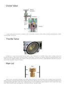
ACV-5 Adjustable Choke Valves ACV-5 adjustable choke valve with operating detail and valve trim options.
ACV-5 adjustable choke valves have wide applications in oil, gas, and water service. Three body sizes allow proper matching of the choke to the expected flow rate. Maximum working pressures to 10,000 psi [68,950 kPa] are available on selected, properly equipped ACV-5 valves. An easily read indicator ring, calibrated in sixtyfourths of an inch, provides accurate flow ® control, and a spring-loaded Teflon packing design forms a bubble-tight stem seal. The valve and seat can be removed by hand, without special tools and without removal of the valve body from the line, by simply removing the bonnet. ACV-5 series valves feature a 1 1/4-in. [31.8-mm] maximum port size.
ACV Series Adjustable Choke Valve
Special trim designs
Closed
Cavnoise Valve Trim
Throttling
Cavrosion-Cavnoise Valve Trim
Ported cage and multiple sleeve designs that will provide protection from deterioration caused by cavitation and erosion are available for ACV-5 valves. Cavitation results from the instantaneous formation of gas bubbles in a fluid. The bubbles are caused by an increase in the fluid velocity at a flow restriction. The increase in fluid velocity is followed by a sudden decrease in fluid pressure to below the vapor pressure of the fluid after the restriction. As the flow continues downstream of the restriction, the pressure recovers and causes the gas bubbles to implode. The energy released by the implosion results in vibration, noise, and pitting of the internal valve surfaces and the piping.
Applications ! Oil, gas, and water service Benefits ! Cavitation and erosion protection ! Noise suppression ! Internal component replacement without removing valve from service Features
! Single-element, externalsleeve trim design
! Multiple-ported sleeve design upstream of the flow-throttling element ! Combination valve trim options available
Erosion damage is caused by particulates or dense fluids flowing at high velocity and impinging on small surface areas. The dissipation of kinetic energy at the trim of most plug and seat, or eclipsing-type choke valves, results in erosion damage. Special trim designs are available in the following configurations.
Cavrosion valve trim This single-element, external-sleeve trim design results in reduced cavitation by creating multiple pressure drops and dividing flow. The Cavrosion* valve trim is used in the same choke body as standard trim, and it is designed to afford the same linear flow characteristics as a standard feature. The valve seat is removed from the high-flow area, and tungsten carbide components are used for throttling the flow. The tungstencarbide-coated throat extends below the seat and allows the cavitation to dissipate within the trim.
Cavnoise valve trim The Cavnoise* valve trim design features one, two, or three stationary, multiple-ported sleeves upstream of the flow-throttling element. This design provides the appropriate number of pressure drop stages required for noise suppression and cavitation control. The sleeves can be used in conjunction with both standard and ported cage trims. Standard sleeve material is precipitation-hardened stainless steel for increased life under severe operating conditions.
ACV-5 Cv Values Flow Coefficient at Max Setting Trim Size
Cv Max
0.750 in. [19.0 mm]
19.3
1.000 in. [25.4 mm]
28.0
1.250 in. [31.8 mm]
35.0
Cavrosion-Cavnoise valve trim combination †
This combination trim assembly combines the features of cavitation, erosion, and noise-control trims for the most effective protection of the valve internals.
Dimensional data reference figure.
†
The Cavrosion-Cavnoise valve trim combination is routinely available only on selected sizes. The combination trim is available for any size by special request.
ACV-5 Dimensional Data Body Style
Threaded
Max Working Pressure (psi [kPa])
2.000 in. [50.8 mm]
5,000 [34,475]
2.500 in. [63.5 mm] Approximate Weight (lbm [kg])
A and B (in. [mm])
C (in. [mm])
3.000 in. [76.2 mm]
A and B (in. [mm])
C (in. [mm])
Approximate Weight (lbm [kg])
A and B (in. [mm])
5.000 [127.0]
13.440 [341.4]
35 [15.9]
5.000 [127.0]
13.440 [341.4]
40 [18.1]
5.000 [127.0]
C (in. [mm])
Approximate Weight (lbm [kg])
13.440 [341.4]
45 [20.4]
3,000 [20,685] Socket weld
3,600 [24,822]
5.000 [127.0]
13.440 [341.4]
35 [15.9]
5.000 [127.0]
13.440 [341.4]
40 [18.1]
5.000 [127.0]
13.440 [341.4]
45 [20.4]
Butt weld 160
6,000 [41,370]
4.500 [114.3]
12.940 [328.7]
35 [15.9]
5.000 [127.0]
13.440 [341.4]
40 [18.1]
5.000 [127.0]
13.440 [341.4]
45 [20.4]
Butt weld XXH
10,000 [68,950]
4.500 [114.3]
12.940 [328.7]
35 [15.9]
5.000 [127.0]
13.440 [341.4]
40 [18.1]
5.000 [127.0]
13.440 [341.4]
45 [20.4]
Series 600 RF
1,480 [10,205]
6.380 [162.1]
14.820 [376.4]
55 [24.9]
6.500 [165.1]
14.940 [379.5]
60 [27.2]
7.000 [177.8]
15.440 [392.2]
65 [29.5]
Series 600 RJ
1,480 [10,205]
6.440 [163.6]
14.880 [378.0]
55 [24.9]
6.560 [166.6]
15.000 [381.0]
60 [27.2]
7.070 [179.6]
15.510 [394.0]
65 [29.5]
Series 900 RF
2,220 [15,307]
7.250 [184.2]
15.680 [398.3]
83 [37.6]
8.250 [209.6]
16.690 [423.9]
88 [39.9]
7.500 [190.5]
15.740 [399.8]
93 [42.2]
Series 900 RJ
2,220 [15,307]
7.310 [185.7]
15.750 [400.1]
83 [37.6]
8.310 [211.1]
16.750 [425.5]
88 [39.9]
7.570 [192.3]
16.010 [406.7]
93 [42.2]
Series 1500 RF
3,705 [25,546]
7.250 [184.2]
15.690 [398.5]
83 [37.6]
8.250 [209.6]
16.690 [423.9]
88 [39.9]
9.250 [235.0]
17.690 [449.3]
93 [42.2]
Series 1500 RJ
3,705 [25,546]
7.310 [185.7]
15.750 [400.1]
83 [37.6]
8.310 [211.1]
16.750 [425.5]
88 [39.9]
9.320 [236.7]
17.760 [451.1]
93 [42.2]
Series 2500 RF
5,000 [34,475]
8.752 [222.3]
17.190 [436.6]
119 [54.0]
10.000 [254.0]
18.440 [468.4]
144 [65.3]
11.300 [287.0]
19.750 [501.7]
233 [105.7]
Series 2500 RJ
5,000 [34,475]
8.941 [227.1]
17.380 [441.5]
119 [54.0]
10.130 [257.3]
18.570 [471.7]
144 [65.3]
11.500 [292.1]
19.940 [506.5]
233 [105.7]
API 2000
2,000 [13,790]
6.441 [163.6]
14.880 [378.0]
55 [24.9]
6.560 [166.6]
15.000 [381.0]
60 [27.2]
7.060 [179.3]
15.500 [393.7]
65 [29.5]
API 3000
3,000 [20,685]
7.311 [185.7]
15.750 [400.1]
83 [37.6]
8.310 [211.1]
16.750 [425.5]
88 [39.9]
7.570 [192.3]
16.010 [406.7]
93 [42.2]
API 5000
5,000 [34,475]
7.311 [185.7]
15.750 [400.1]
83 [37.6]
8.310 [211.1]
16.750 [425.5]
88 [39.9]
9.310 [236.5]
17.750 [450.9]
93 [42.2]
API 10000
10,000 [68,950]
6.921 [175.8]
15.360 [390.1]
119 [54.0]
7.830 [198.9]
16.270 [413.3]
144 [65.3]
8.860 [225.0]
17.300 [439.4]
233 [105.7]
www.slb.com/oilfield AL_03_033_0
©Schlumberger
July 2003
*Mark of Schlumberger