![ASSH Air Cooled Scroll Chiller Manual en Oct 16 2017 [PDF]](https://pdfs.asia/img/200x200/assh-air-cooled-scroll-chiller-manual-en-oct-16-2017.jpg)
5 0 5 MB
Air Cooled Scroll Chiller Unit
Climate 5000
8736862413(20 17/05)CN
ASSH-035D3AE | ASSH-070D3AE | ASSH-135D3AE |
en Installation, Operation and Maintenance Manual Read the manual carefully prior to installation and operation of the unit! Observe the warnings in the manual! Installation by an authorised person only!
WELCOME
WELCOME Distinguished users: Thank you for choosing and using the products of our company! Our products have high quality and excellent performance. For ease of use, please read the manual carefully and operate as per the steps as described in the manual. We will be with you all along. Please feel free to contact us at the number and address on the Warranty Card whenever you have any problems. We are ready to serve you. Due to product improvement, the product you have purchased may be slightly different from those introduced in the Manual. We hereby apologize for the trouble we cause.
Important prompt: Any illustrations and information in this manual are only for reference • Air cooled scroll chiller unit= is the important part of the air conditioning system, which requires expertise and has strict specifications and requirements. Therefore, it must be installed, commissioned, operated and managed by professionally trained technical personnel. • The air conditioner can be used widely, except wet zone, outdoors, the environment with blowing dust and corrosion, and the site with explosion hazard. • Operating conditions: - Power supply: 380V/ 3N~/ 50Hz Our company adheres to the principle of commitment to excellence, and may not inform you of certain improvement in specification, performance, material and structure of such products. Sorry for the inconvenience. Please contact us for obtaining the latest information.
8736862413(2017/05)en
Climate 5000
Table of contents | 2
Table of contents 1 Key to symbols and safety instructions ..... 3 1.1 Explanation of symbols ............................. 3 1.2 Safety information ..................................... 3 1.3 Product description ................................... 3 1.4 Operating limits ......................................... 4 2 Unit information............................................. 5 2.1 Naming rule............................................... 5 2.2 Working principle....................................... 5 2.2.1 Cooling ............................................... 5 2.2.2 Heating............................................... 5 2.3 Unit characteristics.................................... 6 2.4 Component characteristics ....................... 6 2.5 Specifications ............................................ 8 2.6 Performance correction table.................... 9 2.6.1 Cooling capacity and power correction table ................................................... 9 2.6.2 Heating capacity and power correction table ................................................... 9 2.7 Operating range ....................................... 10 2.8 Curves of loss of pressure at the water side 11 2.9 Outlines and dimensions.......................... 12 2.10 Installation foundation ............................ 13
5.4 Error query interface ................................ 33 5.5 Parameter check interface ....................... 33 6 Unit commissioning and operation ............ 35 6.1 Preparation .............................................. 35 6.2 Single unit commissioning ....................... 35 6.3 Joint commissioning................................. 35 7 Maintenance.................................................. 36 8 Common faults and solutions ..................... 38 9 Error code and dialed code setting ............ 41 9.1 Error code ................................................ 41 9.2 Dialed code setting .................................. 42 9.2.1 Address code setting SM1 (DIP1~DIP4) ........................................................... 42 9.2.2 Unit type setting SM1 (DIP5~DIP8) .. 42 9.2.3 Unit model setting SM2 (DIP1~DIP2) 42 10 Packing list ................................................. 43
3 Engineering installation............................... 15 3.1 Unit installation......................................... 15 3.1.1 Preparation before installation .......... 15 3.1.2 Installation position ........................... 15 3.1.3 Handling and lifting ........................... 17 3.2 Electrical installation ................................ 18 3.3 Equipment installation.............................. 23 3.3.1 Water pipe installation....................... 23 3.3.2 Installation of filter............................. 23 3.3.3 Installation of flow switch .................. 24 3.4 Water pipe connection diagram ............... 24 4 Equipment selection .................................... 29 4.1 Selection of water pipe............................. 29 4.2 Selection of water pump .......................... 29 4.3 Selection of electrical heater.................... 29 4.4 Selection of expansion tank ..................... 29 5 Electrical control .......................................... 30 5.1 Description of Handset............................. 30 5.1.1 Basic performance of the handset .... 30 5.1.2 Description of Handset keys ............. 30 5.1.3 Description of basic operation of the handset ............................................. 30 5.2 Initial interface .......................................... 31 5.3 Setting interface ....................................... 31 5.3.1 Time setting interface........................ 31 5.3.2 Timing mode setting.......................... 31 5.3.3 Timing setting interfacet .................... 32 Climate 5000
8736862413(2017/05)en
3 | Key to symbols and safety introductions
1 Key to symbols and safety introductions 1.1 Explanation of symbols Warnings Warnings in this document are framed and identified by a warning triangle which is printed on a grey back- ground. The additional information words indicate the possible consequence and severity due to failure to comply with the measures for hazard prevention. Keywords indicate the seriousness of the hazard in terms of the consequences of not following the safety instructions. • Notice Indicates that material damage may occur. • Caution Indicates that minor to medium injury may occur. • Warning Indicates that serious injury may occur. • Danger Indicates possible risk to life. Important information Important information in cases where there is no risk of personal injury or material losses is identified by the symbol shown on the left. It is bordered by horizontal lines above and below the text. Additional symbols Symbol
Definition
►
a step in an action sequence
misconduct or misoperation, personal injury, even death may occur. The operation/ maintenance personnel shall be responsible and obligated to recognize and confirm such potential risks to protect themselves from hazard. Nonobservance of these safety requirements may result in serious damage of equipment and property and even casualties of themselves and other personnel at site. The Manual is applicable to the operation/ maintenance personnel that have been trained specially and are authorized by the Owner so as to work safely and correctly. What's particularly important is that the Manual, other reference data shall be carefully read and well understood before any operation on equipment. The operation personnel must be familiar with obey all standards and specifications related to operation. The operation/ maintenance personnel shall be obligated to confirm the applicability of these documents to relevant equipment. In case of any doubt before equipment operation, confirm with relevant departments whether equipment has been updated, whether there are latest available documents. Bosch Thermotechnology Corp. adheres to the strategy of continuous product update. There-fore, the information included in the document may be updated without notice. Bosch Thermotechnology Corp. does not commit to provide the latest information to the holders of the Manual actively. However, the user can contact the local Bosch Thermotechnology Corp. for updated information.
a reference to a related part in the document or to other related documents
1.3 Product description
・
a list entry
–
a list entry (second level)
BOSCH Climate 5000 air cooled scroll chiller unit was designed and manufactured by ISO9000 approved Bosch Thermotechnology (Shandong) Co., Ltd. in accordance with strict design and manufacturing standards. It is within the limit specified by the Manual. The quality, reliability and flexibility of various air-condition engineering projects can be ensured effectively. The unit can be used for air-condition in the commercial place and is not applicable to other cases unmentioned by the Manual.
Table 1: Additional symbols
1.2 Safety information The equipment involved in the Manual is very complex, and workers may be exposed to the following environments or risks caused by components during installation, operation, maintenance or repair, including but not limited to refrigerant, machine oil, pressure bearing materials, rotating parts as well as high and low voltage. In case of 8736862413(2017/05)en
The Manual includes all data and operation and maintenance guidances necessary for correct unit installation and commissioning. Please read the Climate 5000
Key to symbols and safety introductions | 4 Manual carefully before unit operation and maintenance. All the work (including installation, commissioning and maintenance) that is described in the Manual detailedly shall only be conducted by the professional technical personnel that go through training. The manufacturer shall not take any responsibility for damage or destruction due to incorrect installation, commissioning, operation or maintenance or nonobservance of process and guidance required in the Manual.
1.4 Operating limits Warning: Please be sure to make a request to the distributor if the user will have the unit operating with return water temperature lower than above lowest setting values. Donot use before necessary protective measures are taken. • Voltage range: - The power supply standard: 380VAC/3N/50Hz - The lowest allowable voltage is 342V - The highest allowable voltage is 418V • The range of unit operating ambient temperature: - Cooling mode: 15°C~46°C - Heating mode: -15°C~25°C - If the ambient temperature is over, the unit would not operate and display P01 • Water temperature control range(Control of return water temperature): - Cooling: lowest 10°C, highest 25°C - Heating: lowest 25°C, highest 50°C • Operating environment: Humidity should be less than 90%, and the height should below 2000 meters above sea level.
Climate 5000
8736862413(2017/05)en
5 | Unit introduction
2 Unit introduction The air cooled scroll chiller system is used to cool down and heat up with the principle of reverse Carnot cycle by making use of cheap air and a small amount of power.
Fin heat exchanger
2.1 Nomenclature
1
6
2
135
3
4
5
D
3
A
9
10
11
Water inlet
E 12
7
8
1
Bosch: brand
2
Climate: category
3
5000: value level
4
Energy: AS - air source; WL - water loop; GW ground water; GL - ground loop
5
Compressor: R - rotary; S - scroll; W - screw; C - centrifugal; T - turbolor
6
Unit function: C - cooling only; H - heat pump
7
Cooling capacity: kW (double digit at least, such as 08 = 8 kW)
8
Heat recovery: PHx– partial heat recovery x%; TH -total heat recovery100%; omit - no heat recovery
9
Refrigerant: A-R22; B-R407C; C-R134a; DR410A
13
Power supply: • 220~230V/50Hz/1 Phase
Drain the high-temperature and high-pressure refrigerant gas compressed by compressor to fin heat exchanger through four-way valve. In the process, heat is drained to the atmosphere and intermediate-temperate and high-pressure liquid refrigerant is generated. Then throttle with the electronic expansion valve to generate low-temperature and low-pressure gas liquid mixture, and exchange it with circulating water in the plate heat exchanger to return to the compressor. A cycle is completed. After exchange with refrigerant, the circulating water reaches the temperature required and then exchanges with indoor air. Cooling is realized. 2.2.2 Heating Fin heat exchanger
• 220~230V/60Hz/1 Phase • 380~400V/50Hz/ 3 Phase • 380~400V/60Hz/ 3 Phase • 110~115V/60Hz/ 1 Phase • 460V/60Hz/ 3 Phase
11
Product sequence: A, B, C, D…N; A1, B1, C1, D1…N1 Nx=customized product, x=null,1,2,3…
12
Climate condition: T-T3; T1- omit
13
Export (out of CN)
Table 2: Nomenclature table
2.2 Working principle 2.2.1 Cooling
Water outlet
Figure 1: Cooling operation diagram
Four-way valve Water inlet Plate HEx
10
Four-way valve
-
Compressor
H
Water outler
Compressor
S
Plate HEx
Bosch Climate 5000 AS
Figure 2: Heating operation diagram Drain the high-temperature and high-pressure refrigerant gas compressed by compressor to plate heat exchanger through four-way valve. After heat
8736862413(2017/05)en
Climate 5000
Unit introduction | 6 exchange with indoor circulating water, heat is drained to the water. The circulating water that has reached the required temperature exchanges with indoor air to realize heating. The high-temperate and high-pressure refrigerant is condensed to intermediate-temperature and high-pressure liquid refrigerant which is throttled to fin heat exchanger with the electronic expansion valve to generate low-temperature and low-pressure gas liquid mixture. After heat exchange with air and absorbing heat in the air, it returns to the compressor. A cycle is completed.
2.3 Unit characteristics • Environmental-friendly refrigerant R410A The refrigerant is R410A that is environmental-friendly and has no damage to ozone sphere is used. • 16 module combinations at most The whole series adopt modular design with 16 module combinations at most and maximum capacity of 2128 kW. Combinations between different capacity models can be realized for convenience of design, installation and transportation. • Heating without shutdown during defrosting The defrosting conditions and time among modules are mutually independent during operation of module combination. When certain module is in defrosting state, other modules out of the defrosting state can still heat water normally to avoid synchronous defrosting of module combination and ensure comfortability. • Multilevel capacity adjustment Each module is designed with multiple independent refrigerant circuits. Multilevel capacity adjustment of single unit can be realized through operating adjustment of compressor. • Broad operating range The unit can make refrigeration at the upper limit of 46°C and heat up at the lower limit of -15°C, so it meets the operating conditions in most areas of the earth. • Convenient installation The unit can be installed in the open areas of roof and ground, instead of special room. Furthermore, with the integral design, the unit can be put into use after connection of water loop and power supply. The fluorine loop can switch automatically. Climate 5000
• Intelligent defrosting The unit is designed with high precision of temperature sensor which can accurately sense the changes of system pressure and temperature in the frosting condition and select the optimum defrosting time intelligently to avoid incomplete or frequent defrosting and other problems. The intelligent defrosting through reversing of four-way valve can ensure reliable, safe and thorough defrosting and complete drainage. • Balanced compressor operation The unit can monitor the operation of each compressor in real time, regulate and balance the operating time of each compressor intelligently and prolong the whole unit life. • Support access to centralized building control system The unit is set with RS485 signal control port to access and integrate into the centralized building control system through Modbus protocol. • Compressor liquid hammer prevention Each compressor of the unit is designed with electrical crankcase heating element. In winter, the refrigerant oil in the compressor of standby unit can also be in good lubrication state and the liquid refrigerant can be separated from the refrigerant oil by gasification to prevent liquid compression during unit startup and compressor damage. • Forced defrosting For heating under severe environment, the unit is also designed with forced defrosting function in addition to intelligent defrosting. In case of thick frost due to high ambient humidity or ice due to extremely low temperature, the forced defrosting function can be activated to remove the frost or ice thoroughly. • Protection function The unit is provided with function of protection for power supply, high pressure, low pressure, discharge, over current, antifreezing in winter, antifreezing during cooling, water flow, etc., to ensure normal operation of the unit all day.
2.4 Component characteristics • High efficiency of scroll compressor The unit is provided with high efficiency of R410A special scroll compressor. It is designed with low-pressure chamber. The motor chamber and crankcase are located in the lower temperature area. The motor is cooled efficiently by low tem8736862413(2017/05)en
7 | Unit introduction temperature refrigerant gas to prolong the life. The high- temperature and high-pressure refrigerant can be exhausted directly after compression to reduce pressure and heat loss and increase energy efficiency. The flexible scroll design increases the capability of liquid hammer prevention and decreases the noise of compressor. • Plate type heat exchanger The plate type heat exchanger is used as evaporator. The system has no sealing gasket structure that exchanges heat through shell and tube. Therefore, the problem of invalid gasket resulting in refrigerant leakage will not occur and it is suitable for long-term use. • Galvanized plate structure The plastic-sprayed hot galvanized plate looks more beautiful and increases corrosion resistance. • Throttling of electronic expansion valve It is throttled with electronic expansion valve. Compared with capillary tube and thermostatic expansion valve, it has broader throttling range. Throttling is normal from -15°C to 46°C, which can ensure compressor operating in optimum state, thereby prolonging the service life of compressor. • Crankcase heating element The heating element is provided with stainless steel knitted round belt type structure which has faster heat conduction speed and longer service life than the belt type heating element commonly used in the air-condition of the market.
8736862413(2017/05)en
Climate 5000
Unit introduction | 8
2.5 Specifications Model
ASSH-035D3AE
ASSH-070D3AE
ASSH-135D3AE
Cooling capacity
kW
32.5
66.5
133
Heating capacity
kW
33
67.5
135
Power supply
V/Ph/Hz
380V/3Ph/50Hz
380V/3Ph/50Hz
380V/3Ph/50Hz
Cooling
kW
10.2
19.9
39.8
Heating
kW
10.3
20.2
40.4
Rated current
A
18.4
35.9
71.8
Startup current
A
128
152.1
200.3
Maximum operating current
A
24
45.8
92.5
Input power
Current
Compressor Refrigerant
Air side
Type
Scroll
Quantity
1
2
4
9.85
9.5×2
9.5×4
R410A
kg
Type
Internally ribbed tube and high-efficiency hydrophilic type louvered aluminum fin
Type of fan
Axial flow fan
Quantity of fans 3
Dimension
4
m /h
13000
13000×2
13000×4
Fan motor input
kW
0.75
0.75×2
0.75×4
Plate m3/h
5.6
11.4
22.9
water resistance loss kPa
28
36
36
Connection type of water pipe
External thread
Flange DN50
DN80
Water flow volume
Weight
2
Air volume Type
Water side
1
Diameter of connecting pipe
mm
DN40
Working pressure
MPa
1.6
Net weight
kg
399
642
1150
Gross weight
kg
406
652
1160
Operating weight
kg
431
693
1242
Net dimension (W* D* H)
mm
1050*1293*2030
1050*2150*2030
1909*2150*2030
Table 3: Performance parameter table • Please pay attention to the followings: - The working conditions of standerd cooling capacity are 12°C of inlet water temperature, 7°C of outlet water temperature and 35°C of outdoor environmental dry-bulb temperature. - The working conditions of standerd heating capacity are inlet water temperature 40°C, outlet water temperature 45°C, outdoor environmental dry-bulb temperature 7°C and wet-bulb temperature 6°C. - The specification parameters in the table may vary with the changes of manufacturer's product design without notice. Climate 5000
8736862413(2017/05)en
9 | Unit introduction
2.6 Performance correction table 2.6.1 Cooling capacity and power correction table Environment temperature °C Water outlet temp. °C
15
20
25
30
35
40
46
CapCapCapCapCapCapCapPower acity Power Power Power acity Power Power acity Power acity acity acity acity
5
1.11
0.75
1.05
0.80
1.00
0.85
0.96
0.92
0.91
0.98
0.84
1.08
0.77
1.17
7
1.18
0.77
1.13
0.82
1.07
0.87
1.04
0.94
1.00
1.00
0.91
1.09
0.83
1.19
9
1.25
0.79
1.20
0.84
1.14
0.89
1.10
0.96
1.06
1.02
0.98
1.12
0.89
1.21
12
1.35
0.83
1.30
0.88
1.25
0.92
1.20
0.99
1.16
1.06
1.07
1.15
0.98
1.24
15
1.45
0.86
1.40
0.91
1.35
0.95
1.30
1.02
1.26
1.09
1.17
1.19
1.08
1.28
Table 4:Cooling capacity and power correction table 2.6.2 Heating capacity and power correction table • Capacity corrective table Environment temperature °C Water outlet temp. °C
-15
-10
-5
0
7
10
15
21
25
CapCapCapCapCapCapCapCapCapPower Power Power Power Power Power Power Power Power acity acity acity acity acity acity acity acity acity
30
0.54 0.72 0.64 0.73 0.72 0.74 0.83 0.75 1.06 0.76 1.08 0.76 1.10 0.77 1.22 0.77 1.27 0.78
35
0.52 0.80 0.62 0.80 0.70 0.81 0.82 0.82 1.04 0.83 1.06 0.84 1.08 0.84 1.21 0.85 1.26 0.87
40
0.50 0.87 0.60 0.88 0.68 0.88 0.79 0.90 1.02 0.91 1.04 0.92 1.06 0.92 1.19 0.93 1.24 0.96
45
0.48 0.96 0.58 0.97 0.66 0.98 0.77 0.99 1.00 1.00 1.02 1.01 1.04 1.02 1.17 1.03 1.22 1.06
50
-
-
-
-
-
-
55
-
-
-
-
-
-
0.75 1.09 0.97 1.10 0.98 1.10 1.02 1.11 1.14 1.13 1.19 1.17 -
-
0.93 1.20 0.95 1.21 0.99 1.21 1.12 1.24 1.16 1.25
Table 5:Heating capacity and power correction table 8736862413(2017/05)en
Climate 5000
Unit introduction | 10
2.7 Performance correction curves • Cooling operating range
Outlet water temperature(°C)
25 15, 20
46, 20
15, 5
46, 5
20 15 10 5 0 10
15
20
25
30
35
40
45
50
Ambient temperature (°C) Figure 3: Power correction curve - heating • Heating operating range
Outlet water temperature(°C)
60
10, 55
25, 55
55 50
-15, 45
45 40 35
-15, 30
25, 30
30 25 -20
-10
0
10
20
30
Ambient temperature (°C) Figure 4: Power correction curve - heating Climate 5000
8736862413(2017/05)en
11 | Unit introduction
2.8 Curves of loss of pressure at the water side • ASSH-035D3AE curve of water resistance loss
water resistance loss (KPa)
ASSH-035D3AE Water flow-loss of pressure (water temperature 9.5°C) 60 55 50 45 40 35 30 25 20 15 10
3
5
7
9
Water flow (m /h) 3
Figure 5: ASSH-035D3AE curves of loss of pressure at the water side • ASSH-070D3AE curve of water resistance loss
water resistance loss (KPa)
ASSH-070D3AE Water flow-loss of pressure (water temperature 9.5°C) 50 45 40 35 30 25 20
8
9
10
11
12
Water flow (m3/h)
13
14
Figure 6: ASSH-070D3AE curves of loss of pressure at the water side • ASSH-135D3AE curve of loss of water resistance loss
water resistance loss (KPa)
ASSH-135D3AE Water flow-loss of pressure (water temperature 9.5°C) 50 45 40 35 30 25 20
16
18
20
22
24
Water flow (m3/h)
26
28
Figure 7: ASSH-135D3AE curves of loss of pressure at the water side 8736862413(2017/05)en
Climate 5000
Unit introduction | 12
2.9 Outlines and dimensions Model
Dimension (mm)
Diameter Connecof water tion pipe mode
A
B
C
D
E
F
G
H
I
ASSH-035D3AE
68
162.5
900
1293
1050
470
154
2030
645
DN40 Thread
ASSH-070D3AE
100
450
1150
2150
1050
470
153
2030
645
DN50
ASSH-135D3AE
100
330
1390
2150
1909
398
154
2030
986
DN80
Flange
Table 6: Outline and dimension table
Water inlet
Unit bolt hole
Water outlet
Figure 8: ASSH-035D3AE demension
Water inlet
Unit bolt hole
Water outlet
Figure 9: ASSH-070D3AE demension Climate 5000
8736862413(2017/05)en
13 | Unit introduction
Water inlet Water outlet
Unit bolt hole
Figure 10: ASSH-135D3AE demension
2.10 Installation foundation • Please pay attention to the followings: - The basement is subject to concrete structure or channel steel frame which can bear the operating weight. - Each unit is fixed with four M12 bolts. The unit of dimension in the drawings is mm. - The unit basement is provided with 40 mm of rubber pad for shock absorption. - The foundation bolt holes of unit are located on the unit chassis. Drawings only show the locations of foundation bolt holes for the convenience of engineer construction. - If the unit is installed on the roof, then you must install the corresponding spring shock absorber.
Water inlet
300
Water outlet
Unit bolt hole M12
≥262.5
≥1425 900 ≥262.5
≥400
990
≥450
990
Unit bolt M12×220 990
≥400
≥100
≥100
≥(n-1)x1440+1790
Figure 11: ASSH-035D3AE installation foundation 8736862413(2017/05)en
Climate 5000
Unit introduction | 14
300
Water inlet Water outlet
Unit bolt hole M12 970
≥450
970
≥100
1150
≥550
≥2250
≥550
≥400
Unit bolt M12×220 ≥400 970
≥100
≥(n-1)x1420+1770
Figure 12: ASSH-070D3AE installation foundation
Water inlet
300
Water outlet
Unit bolt hole M12
≥2250 ≥430 1390 ≥430
≥400
1821
≥450
1821
Unit bolt M12×220
1821 ≥400
≥100
≥100
≥(n-1)x2271+2621 Figure 13: ASSH-135D3AE installation foundation Climate 5000
8736862413(2017/05)en
15 | Engineering installation
3 Engineering installation 3.1 Unit installation The unit installation shall be conducted by professionals.
• Installation of single unit ≥1800mm
≥1800mm
3.1.1 Preparation before installation ►
Check the unit and relevant fittings for integrity. In case of missing, contact the local distributor timely.
►
Inspect the unit carefully to verify whether the goods are damaged due to transportation.
►
Prepare the tools for installation, such as pressure guage, thermal container, etc.
3.1.2 Installation position ≥3000mm
The walls should not exceed two sides when install the unit, the chart just one form of install, and the distance between unit and walls should exceed 1800mm in order to get more airflow. The installation position of module unit shall be selected reasonably to ensure its operating efficiency meets the objectives and requirements. It shall be selected from the following aspects: • Air cooled sroll chiller unit shall be installed on steady and firm bearing surface. • Air cooled sroll chiller unit and indoor heat exchanger shall be as close as possible to reduce the length of cooling pipe and the quantity of bends as far as possible. However, certain distance is required. • Air cooled sroll chiller unit shall not be installed by the window or among buildings to prevent normal operating noise from entering rooms. • Airflow at the inlet and outlet shall be free from obstruction. • The area with good ventilation condition shall be selected so that the unit can absorb and exhaust sufficient air. • =Units shall be away from the area with inflammables, explosives, severe dust, salt mist and other polluted air.
≥1800mm
≥1800mm
Figure 14: Single unit installation Notice: During single installation, the quantity of the wall shouldn’ t more than two faces. The figures below are one of the installation forms for reference only. The distance between the unit and the wall should less than 1800mm. Otherwise, it will influence the air flow.
A module unit can be installed in a place independently or several units can also share one place. See the figure below for detailed installation space (the following figures show the same unit but the installation dimension is applicable to all types of units). 8736862413(2017/05)en
Climate 5000
Engineering installation | 17 • Installation of modular unit D
C ≥1000mm
Row R
B
Column N
• Please pay attention to the followings: - There have several install forms for module unit install are listed on above, more walls is unreasonable. - When the distance (H) between airflow outlet and celling exceed 2300, the C and D bigger than 2000mm, when H Less than or equal 2300, the C and D bigger than (H-300) mm. - When N=1, 2 and R≥2 or 2≤R≤4 and N≥3, the B is 400mm. When N=3 and R≥5, the B is 600mm. When N=4 and R≥5 or N=5 and R≥5, the B is 800mm. When R=6 and N≥5, the B is1200mm. When N=5 and R≥7 or R=8 and N≥7, the B is 1600mm. When N=7, 8 and R≥8 or R=9 and N≥9, the B is 2000mm. - When the two walls connect each other, like the first chart, the row need plus 2 and the column need plus 1 on original numerical. 3.1.3 Handling and lifting All units have gone through strict inspections and tests before leaving factory to ensure the unit performance and quality. The user shall be very careful during installation and handling to avoid damage of control system and piping components. Before unpacking, the unit shall be transported to the place as close to the final installation position as possible and then kept upwards. The unit that has been unpacked shall be handled with the following methods: Lifting hook
Lifting sling
Lifting bar Figure 15: Modular unit installation Climate 5000
Figure 16: Handling and lifting 8736862413(2017/05)en
18 | Engineering installation • Control for electrical assisted heater
3.2 Electrical installation • Wiring ► The
rated voltage and the circuit specially used for air-condition shall be adopted.
► The
power line shall be free from forced pulling.
► All
electrical installations shall be conducted by professionals in accordance with local laws, rules and the Manual.
► The
diameter of flexible power line shall be large enough. The damaged flexible power line and connecting line shall be replaced with special flexible line.
► Wires
shall be grounded to the special grounding device of building reliably by professionals.
Master unit
Figure 17: Electrical connection diagram 8736862413(2017/05)en
* Please install current leakage protective circuit-breaker of input-wire for each unit.
Slave unit 2 Slave unit 1
Slave unit 15
R S T N R S T N
Current leakage protective circuitbreaker of input-wire
X1 L1 L2 L3 N
I?
I?
I?
R S T N
R S T N
I?
• Connection diagram of power supply line
Notice: On control cabinet there is only control contact port is necessary to install individual power and safety protection device for the electrical assisted heater. The electrical assisted heater starts to provide auxiliary heating function when in low temperature condition. Connect the inlet and outlet of electrical assisted heater serially to the outlet mains of air cooled scroll chiller unit. The electrical control cabinet of main unit module provides controlled contacts to assisted heater (only on-off output control signal is provided and the control of electric heater will be provided by the user). The electric heater will start after the compressor starts and when the actual ambient temperature is lower than the starting ambient temperature and the outlet water temperature is lower than starting outlet water temperature. When the actual ambient temperature or outlet water temperature is higher than shutdown temperature or after the compressor shuts down, the corresponding electric heater stops. • Control for water pump operation (effective only when the water pump and air-condition are in the linkage control condition). Notice: Water pump choose need meet the requirement of the unit, the toleration of water pump water flow is 85%-120% compared with nameplate. The control cabinet of air-condition provides linkage control contact of chilled water pump (only on-off output control signal is provided and the control of water pump will be provided by the user). In the shutdown state, when the return water temperature is lower than or equal to 5°C and the ambient temperature is lower than 10°C, start the water pump and a module for heating. Then start or shut modules as required. Stop heating and antifreezing when the return water temperature is up to 25°C. - Please pay attention to the followings: When multiple units share a set of water pipe system, all water pumps (except for the standby ones) will start once the unit starts. It is prohibited to determine the quantity of water pumps to be operated based on the quantity of units under operation. The selection of water pump shall meet the unit requirement: the water flow and nominal values on nameplate shall not exceed 85%-120%. • Terminal linkage control Connect the passive normally open contact of terClimate 5000
Engineering installation | 19 minal controller (it is disconnected when the terminal is not started while connected when the terminal is started) to the linkage contact inside the control cabinet of main module. In the startup state, the air-condition will start up automatically when one terminal starts at least, while it will shut down after delay automatically when all terminals are closed.
• Circuit installation diagram Warning: There is high voltage in control cabinet, make sure do not touch any live parts except the control panel, or open the control cabinet, before cut off the power supply.
The linkage contact inside the control cabinet shall be in short circuit if the terminal linkage control of unit is not used Considerations during electrical wiring: ► The
unit wiring only refers to the arrangement of power supply line and communication control line. The control line inside the electrical control cabinet attached to the unit has been well connected in factory and shall not be changed by the user at will.
► The
unit wires are connected with earrings. The selection of power line and circuit breaker is closely related to local climate, soil properties, cable laying modes and so on. Such unit engineering project is generally designed by designing institute and finally subject to the calculation and selection results of the designing institute based on maximum unit power (current).
► The
communication line shall not be grounded at a single point before the unit is grounded reliably. Otherwise, the single point grounding will be disturbed. The distance between AWG20-22 communication line and strong current shall be over 10cm.
► The
unit working current is shown in the following table. Wiring must ensure the unit can work normally. line (mm2)
current(A) Unit model Rated Max. ASSH035D3AE ASSH070D3AE ASSH135D3AE
18.4
24
35.9 71.8
Starting 128
Firing Null
Grounding
10×3
6
10
45.8 152.1
25×3
6
16
92.5 200.3
70×3
6
35
Table 7: Working current control table
Climate 5000
8736862413(2017/05)en
R
S
B
T
1
代号ABR CT COMPa FANa EVa
B
N
2
CN16
电流采样板 系统A压缩机 系统A风机 系统A电子膨胀阀
CN15
8 9
A1
CN12
A2 L1
7
1
4
A
5
CN11
4
1 2 3
3
5
1
A1
CN10
2
3
CN9
21
蓝色 Blue,1.5m㎡ 蓝色 Blue,0.75m㎡
4
A2 L1
红色 Red,4.0m㎡
3
A
CT1
A
Wire Specifications
CN8
2
B
C
5
A
CN18
CN19
CN21
CN22
水泵接触器线圈 Pump Contactor Coil
CN20 CN23
CN24
对照表 Table Current Sampling Board Compresser System A Fan Motor System A Electronic Expansion Valve System A
CN17
CN7 CN6
AC_N
绿色 Green,1.5m㎡ 红色 Red,1.5m㎡ 黄色 Yellow,0.75m㎡
9
Wire Specifications
8
线束规格 黄/绿色 Y/G,4.0m㎡ 黄色 Yellow,1.5m㎡
6 7
端子排接口板 Terminal Interface Board
CN13
CT2
C
2
6
线束规格
CN26
CN5
8
2 2
PSc/TH1
CN27
CN4
CN431
8
CN427
CT7 CN435 CT8
CT5 CN433 CT6
CT3 CN434 CT4
CT1 CN432 CT2
TH3
PSd/TH2 T S CN401 R N 6.3A/250VAC
CN28
CN3
3
3
TH4
Wire Specifications
绿色 Green,0.75m㎡ 红色 Red,0.75m㎡
线束规格
4
TH6
CN2
PSb
PSa
TH5
1
ON
1
ON
4
2
4
4
5
5
User Wiring
Factory Wiring
供应商接线 Supplier Wiring 用户接线
工厂接线
7
6
8
8
CN469 CN466
7
6
CN462
U14
CN450 CN441
4
4
CN439
CN440
CN426
备选件 Optional
4
CN443
接上位机监控 To PC
SW1地址设置:
BA板 BA Board
CN457
主板 Main Board
TH11 TH13 TH15 TH17 TH19 TH21 TH23 TH24 TH26 TH10 TH12 TH14 TH16 TH18 TH20 TH22 TH25
WIREC MODBUS
CN29
CN1
4
3
3
SW2
2
2
TH9
SW1
TH8
CN451
TH7
导线标识 Wire Graphic
4
手操器 (Address Set:) Handset DIP1 DIP2 DIP3 DIP4 地址(Address) ON ON ON ON 主机0(master0) ON ON ON OFF 从机1(slave1) ON ON OFF ON 从机2(slave2) 备注 ON ON OFF OFF 从机3(slave3) Remarks ON OFF ON ON 从机4(slave4) 1.正常出厂设置:联动开关短接 ON OFF ON OFF 从机5(slave5) EX-factory setting: Air terminal unit interlock ON OFF OFF ON 从机6(slave6) control short connected, ON OFF OFF OFF 从机7(slave7) 2.拨码设置 Dialed code setting: OFF ON ON ON 从机8(slave8) DIP1-4:地址设置 address setting, OFF ON ON OFF 从机9(slave9) DIP5: ON-单冷 cooling only、OFF-热泵 heat pump OFF ON OFF ON 从机10(slave10) DIP : 6 7 8 机型 type OFF ON OFF OFF 从机11(slave11) OFF OFF ON ON 从机12(slave12) OFF OFF OFF 35 OFF OFF ON OFF 从机13(slave13) 3.后期如有改动,不另通知 OFF OFF OFF ON 从机14(slave14) No special notice is given if there is any change OFF OFF OFF OFF 从机15(slave15)
CN25
B C
D_OUT20
A-L1 A-L2 A-L3 B-L1 B-L2 B-L3
CN14
A
电源指示灯 Power Light
5
X1
KM2
黄色 Yellow,4.0m㎡ 绿色 Green,4.0m㎡
KM1
1
COMPa
2
D_OUT23
LPa HPa
CC-Ha N CC-Hb PUMP N AH 4WVa N 4WVb Wpump N WAH N ALARM 4WVa2 N 4WVb2
TDa
L1 L2 L3 N PE
D_OUT19
FANa
D_OUT17
CC-Ha
D_OUT11
AH
D_OUT10
4WVa
D_OUT9
NEXT
Eva1 N Eva2
D_OUT22
Eva3 N Eva4 Evb1 N Evb2 Evb3 N Evb4
D_OUT21
FPa LS FS
TSa D_OUT8
ALARM
D_OUT18
LPa OV HPa LPb OV HPb
Te Tr TOa D_OUT16
FPab OV LS FS OV WCV DIN9 OV DIN10
D_OUT15
MOUDBUS通讯接口 MOUDBUS Communication Interface
D_IN7 D_IN6 D_IN5 D_IN4 D_IN3 D_IN2 D_IN1 GND
PSa
TCa D_OUT13 D_OUT14
DIN11 OV DIN12
D_OUT12
GND Aout +5V
D_OUT7
GND Bout +5V
D_OUT6
A1 B1
D_OUT5
+12V GND
D_OUT4
B2
D_OUT3
GND A2
D_OUT2
+5V
D_OUT1
COMPa FANa
EVd EVc EVb EVa
8736862413(2017/05)en 4
5
EVa
380V~400V/50Hz/3PH
ASSH035D3AE 模块机线路图 ASSH035D3AE Module Wiring Diagram
对照表 Table 系统A压力传感器 Pressure Sensor System A 系统A定频排气温传 Discharge Comp Temp System A 室外环境温传 Ambient Temp 系统回水温传 Water In Temp 系统A出水温传 Water Out Temp System A 系统A室外盘管出口温传 Coli Out Temp System A 系统A吸气温传 Suction Temp System A
对照表 Table 系统A低压开关 Low Pressure Switch System A 系统A高压开关 High Pressure Switch System A 系统A风机保护 Fan Protection System A 联动开关 Line Switch 空调测流量开关 Flow Switch
对照表 Table 系统A曲轴加热 Crankcase Heater System A 空调辅助电加热 Eletrical Assisted Heater 系统A四通阀 4 Way Valve System A 输出报警信号 Output Alarm
博世热力技术(山东)有限公司 Bosch Thermo Technology (Shandong) Co., Ltd.
TSa
TCa
TOa
Tr
Te
TDa
PSa
代号ABR
FS
LS
FPa
HPa
LPa
代号ABR
ALARM
4WVa
AH
CC-Ha
代号ABR
20 | Engineering installation • ASSH-035D3A
Figure 18: ASSH-035D3AE Circuit installation diagram
Climate 5000
B
1
B
N
A
2
C
代号ABR CT COMPa COMPb FANa FANb EVa EVb
CN15
8 9
A1
CN12
A2 L1
7
1
4
4
2
CN11
CT4
5
1 2 3
3
5
4
3
2
1
A1
A2
2
L1
CN10
3
21
A
A
5
CN9
A
CT1
A
蓝色 Blue,1.5m㎡ 蓝色 Blue,0.75m㎡
红色 Red,4.0m㎡
2
2
1
A1
3
3
CN8
2
A2 L1
1
1
A
21
CN7
CT3
CN17
电流采样板 系统A压缩机 系统B压缩机 系统A风机 系统B风机 系统A电子膨胀阀 系统B电子膨胀阀
CN16
CN18
CN19
CN21
CN22
2
CN6
AC_N
CN24
CN25
A
8
CN5
B
C
C
B
2 2
2 2
绿色 Green,0.75m㎡ 红色 Red,0.75m㎡
线束规格 Wire Specifications
CN27
CN4
CN431
8
CN427
CT7 CN435 CT8
CT5 CN433 CT6
CT3 CN434 CT4
CT1 CT1 CN432 CT2
PSc/TH1 TH3
PSd/TH2 T S CN401 R N 6.3A/250VAC
3
CN28
CN3
3
3
TH4
4
TH6
CN2
3
PSb
PSa
TH5
1
ON
1
ON
4
2
4
3
5
5
用户接线
User Wiring
Factory Wiring
供应商接线 Supplier Wiring 工厂接线
7
6
8
8
CN469 CN466
7
6
CN462
U14
CN450 CN441
4
4
CN439
CN440
SW1地址设置:
4
4
5
ASSH070D3AE模块机线路图 ASSH070D3AE Module Wiring Diagram
对照表 Table 系统A曲轴加热 Crankcase Heater System A 系统B曲轴加热 Crankcase Heater System B 空调辅助电加热 Eletrical Assisted Heater 系统A四通阀 4 Way Valve System A 系统B四通阀 4 Way Valve System B 输出报警信号 Output Alarm 系统A低压开关 Low Pressure Switch System A 系统A高压开关 High Pressure Switch System A 系统B低压开关 Low Pressure Switch System B 系统B高压开关 High Pressure Switch System B 系统AB风机保护 Fan Protection System AB 联动开关 Line Switch 空调测流量开关 Flow Switch 系统A压力传感器 Pressure Sensor System A 系统B压力传感器 Pressure Sensor System B 系统A定频排气温传 Discharge Comp Temp System A 系统B定频排气温传 Discharge Comp Temp System B 室外环境温传 Ambient Temp 系统回水温传 Water In Temp 系统出AB水温传 Water Out Temp System AB 系统A室外盘管出口温传 Coli Out Temp System A 系统B室外盘管出口温传 Coli Out Temp System B 系统A吸气温传 Suction Temp System A 系统B吸气温传 Suction Temp System B
博世热力技术(山东)有限公司 Bosch Thermo Technology (Shandong) Co., Ltd.
TSb
TSa
TCb
TCa
TOab
Tr
Te
TDb
TDa
PSb
PSa
FS
LS
FPab
HPb
LPb
HPa 5
ALARM
4WVb
4WVa
AH
CC-Hb
CC-Ha
代号ABR
LPa
备选件 Optional
4
CN443
CN426
接上位机监控 To PC
BA板 BA Board
CN457
主板 Main Board
TH11 TH13 TH15 TH17 TH19 TH21 TH23 TH24 TH26 TH10 TH12 TH14 TH16 TH18 TH20 TH22 TH25
WIREC MODBUS
CN29
CN1
4
4
3
SW1
TH9
SW2
2
2
TH8
CN451
TH7
导线标识 Wire Graphic
手操器 (Address Set:) Handset DIP1 DIP2 DIP3 DIP4 地址(Address) ON ON ON ON 主机0(master0) ON ON ON OFF 从机1(slave1) ON ON OFF ON 从机2(slave2) 备注 ON ON OFF OFF 从机3(slave3) Remarks ON OFF ON ON 从机4(slave4) ON OFF ON OFF 从机5(slave5) 1.正常出厂设置:联动开关短接 ON OFF OFF ON 从机6(slave6) EX-factory setting: Air terminal unit interlock ON OFF OFF OFF 从机7(slave7) control short connected, ON ON ON 从机8(slave8) OFF 2.拨码设置 Dialed code setting: OFF ON ON OFF 从机9(slave9) DIP1-4:地址设置 address setting, ON OFF OFF ON 从机10(slave10) DIP5: ON-单冷 cooling only、OFF-热泵 heat pump OFF ON OFF OFF 从机11(slave11) DIP : 6 7 8 机型 type OFF OFF ON ON 从机12(slave12) OFF OFF ON 70 OFF OFF ON OFF 从机13(slave13) 3.后期如有改动,不另通知 OFF OFF OFF ON 从机14(slave14) No special notice is given if there is any change OFF OFF OFF OFF 从机15(slave15)
CN26
水泵接触器线圈 Pump Contactor Coil
CN23
水泵接触器线圈 Pump Contactor Coil 对照表 Table Current Sampling Board Compresser System A Compresser System B Fan Motor System A Fan Motor System B Electronic Expansion Valve System A Electronic Expansion Valve System B
CN20
5
绿色 Green,1.5m㎡ 红色 Red,1.5m㎡ 黄色 Yellow,0.75m㎡
9
7 8
线束规格 Wire Specifications 黄/绿色 Y/G,4.0m㎡ 黄色 Yellow,1.5m㎡
6
端子排接口板 Terminal Interface Board
CN13
B
CT2
C
2
6
A-L1 A-L2 A-L3 B-L1 B-L2 B-L3
CN14
A
电源指示灯 Power Light
5
T
QF1
KM3
S
KM1
R
KM2
X1
COMPa
QF2
线束规格 Wire Specifications
COMPb
TDa TDb
黄色 Yellow,4.0m㎡ 绿色 Green,4.0m㎡
MOUDBUS通讯接口 MOUDBUS Communication Interface
1
D_OUT23
LPa HPa LPb HPb
CC-Ha N CC-Hb PUMP N AH 4WVa N 4WVb Wpump N WAH N ALARM 4WVa2 N 4WVb2
COMPb
L1 L2 L3 N PE
D_OUT20
FANa
D_OUT19
FANb
D_OUT18
CC-Ha
D_OUT17
CC-Hb
D_OUT11
AH 4WVa
D_OUT10
4WVb
D_OUT9
ALARM
D_OUT8
PSb NEXT
Eva1 N Eva2
D_OUT22
Eva3 N Eva4 Evb1 N Evb2 Evb3 N Evb4
D_OUT21
FPab LS FS
FANa
D_IN7 D_IN6 D_IN5 D_IN4 D_IN3 D_IN2 D_IN1 GND
PSa
Te Tr TOab D_OUT16
LPa OV HPa LPb OV HPb
D_OUT15
FPab OV LS FS OV WCV DIN9 OV DIN10
D_OUT13 D_OUT14
DIN11 OV DIN12
TCa TCb D_OUT12
GND Aout +5V
D_OUT6
GND Bout +5V
TSa TSb D_OUT7
+5V
D_OUT5
A1 B1
D_OUT4
+12V GND
D_OUT3
B2
D_OUT1
GND A2
D_OUT2 COMPa
EVd EVc EVb EVa
Climate 5000 EVa EVb
380V~400V/50Hz/3PH
Engineering installation | 21
• ASSH-070D3A
Figure 19: ASSH-070D3AE Circuit installation diagram
8736862413(2017/05)en
B
1
代号ABR CT COMPa COMPb COMPc COMPd FANa FANb FANc FANd EVa EVb EVc EVd
4
电源指示灯 Power Light
5
T
2
1
2
3
A
3
CN14
A1
A2 L1
1
1
6
电流采样板 系统A压缩机 系统B压缩机 系统C压缩机 系统D压缩机 系统A风机 系统B风机 系统C风机 系统D风机 系统A电子膨胀阀 系统B电子膨胀阀 系统C电子膨胀阀 系统D电子膨胀阀
CN15
21
5
2
CT1
2 QF1
A-L1 A-L2 A-L3
N
2
1
A1
3
A
3
4
21
5
2
CT2
QF2
2
A1
CN12
A
1
2
A2 L1
1
3
3
A
21
5
A
2
1
A1
2
A2 L1
1
CN11
2
CT3
QF3
3
A
3
21
5
2
CT4
QF4
蓝色 Blue,0.75m ㎡
5
1
蓝色 Blue,1.5m ㎡
4
1
红色 Red,4.0m ㎡
3
CN10
A
9
8
7
A
A1
9
8
B C
B
CN9
A C
5 7 8 9
A
A1
B
A2 L1
CN8
C
黄色 Yellow,0.75m ㎡
A
A2 L1
7
红色 Red,1.5m ㎡
9
QF5
绿色 Green,1.5m ㎡
8
1
黄色 Yellow,1.5m ㎡
A B
CN17
C-L1 C-L2 C-L3
CN18
D-L1 D-L2 D-L3
对照表 Table Current Sampling Board Compresser System A Compresser System B Compresser System C Compresser System D Fan Motor System A Fan Motor System B Fan Motor System C Fan Motor System D Electronic Expansion Valve System Electronic Expansion Valve System Electronic Expansion Valve System Electronic Expansion Valve System
CN16
B-L1 B-L2 B-L3
CN19
A B C D
CN20 CN21
CN22
CN23
AC_N
CN7 CN6
C
线束规格 Wire Specifications 黄/绿色 Y/G,4.0m ㎡
6 7
端子排接口板 Terminal Interface Board
CN13
A
1
2
A2 L1
1
3
FANc
S
KM3
COMPc
FANd
R
线束规格 Wire Specifications
黄色 Yellow,4.0m ㎡
CC-Ha
KM1
绿色 Green,4.0m ㎡
CC-Hb CC-Hc CC-Hd
COMPa
KM4
COMPd
CC-Ha N CC-Hb CC-Hc N CC-Hd PUMP N AH 4WVa N 4WVb
X1
KM2
COMPb
1
KM5
2
KM6
4WVc N 4WVd
KM1-A1
CN24
2
B
2
4
CN5
8
CN2
2
C
CT
5
6
CN4
CN3
2
红色 Red,0.75m ㎡
CN25
CN1
A
绿色 Green,0.75m ㎡
CN4
线束规格 Wire Specifications B C
3
2
CN26
CN3
3
3
3
2 2
2 2
2 2
2 2 4 3
3
CT1 CN432
CT8
CT7
3
CN431
8
CN435
CT5 CN433 CT6
CT3 CN434 CT4
CT2
TH5
3
2
4
3
4
CN2
3
6
导线标识 Wire Graphic
用户接线
工厂接线
4
4
5
5
6
6
SW1
7
7
8
8
4
3 33
PSd/TH2
PSc/TH1
SW2
3
3
CN451 CN469
U14
CN466
CN457
BA板 BA Board
SW1地址设置: DIP2 ON ON ON ON OFF OFF OFF OFF ON ON ON ON OFF OFF OFF OFF
DIP3 ON ON OFF OFF ON ON OFF OFF ON ON OFF OFF ON ON OFF OFF
CN450
4
备选件 Optional
2
CN462
CN439
CN426
EVa
接上位机监控 To PC
DIP4 地址(Address) ON 主机0(master0) OFF 从机1(slave1) ON 从机2(slave2) OFF 从机3(slave3) ON 从机4(slave4) OFF 从机5(slave5) ON 从机6(slave6) OFF 从机7(slave7) ON 从机8(slave8) OFF 从机9(slave9) ON 从机10(slave10) OFF 从机11(slave11) ON 从机12(slave12) OFF 从机13(slave13) ON 从机14(slave14) OFF 从机15(slave15)
(Address Set:)
手操器 Handset
2
2
主板 Main Board
User wiring
Factory wiring
供应商接线 Supplier wiring
CN441 CN443
CN440
EVb
TH9 TH11 TH13 TH15 TH17 TH19 TH21 TH23 TH24 TH26 TH25 TH10 TH12 TH14 TH16 TH18 TH20 TH22 EVc EVd
DIP1 ON ON ON ON ON ON ON ON OFF OFF OFF OFF OFF OFF OFF OFF
MODBUS
CN27 WIREC
3
PSb
1
ON
1
ON
TH8
PSa
TH7
CN1
TH6 T TH4 S CN401 R N 6.3A/250VAC
TH3
CN427
1
2
3
4
1
2
3
4
1
2
3
4
1
2
备注 Remarks 1.正常出厂设置:联动开关短接 EX-factory setting: Air terminal unit interlock control short connected, 2.拨码设置 Dialed code setting: DIP1-4:地址设置 address setting, DIP5: ON-单冷 cooling only、OFF-热泵 heat pump DIP : 6 7 8 机型 type OFF ON OFF 135 3.后期如有改动,不另通知 No special notice is given if there is any change
水泵接触器线圈 Pump Contactor Coil
4WVd
L1 L2 L3 N PE
KM2-A1
AH 4WVa
D_OUT22
4WVb 4WVc
D_OUT23
FANa
KM5-A1
FANb
KM6-A1
ALARM N
KM3-A1
LS FS LPa HPa LPc HPc
KM4-A1
PSb
KM4-A1
ALARM
D_OUT21
+5V
KM3-A1
LS 0V FS LPa 0V HPa LPc 0V HPc
TDa TDb TDc TDd D_IN12 D_IN11 D_IN10 D_IN9 D_IN8 GND
KM6-A1
+5V
D_OUT20
NEXT
D_IN7 D_IN6 D_IN5 D_IN4 D_IN3 D_IN2 D_IN1 GND
PSa
D_OUT17
FPab 0V FPcd LPb 0V HPb LPd 0V HPd
D_OUT16
FPab FPcd LPb HPb LPd HPd
D_OUT11
Dout
D_OUT12
PSd
D_OUT13
+5V
D_OUT14
Bout OV Aout
D_OUT9
OV Cout
D_OUT8
+5V
D_OUT10
+5V
D_OUT7
PSc
D_OUT6
+12V GND A1
D_OUT18
KM2-A1
4
KM1-A1
B1
D_OUT19
KM5-A1
A2 B2
D_OUT4
GND
Te Tr TOab TOcd TCa TCb TCc TCd TSa TSb TSc TSd D_OUT15
FANcd
D_OUT5
COMPd
D_OUT3
COMPc
D_OUT2
COMPa FANab
8736862413(2017/05)en D_OUT1
COMPb
380V~400V/50Hz/3PH
4
4
4
5
5
对照表 Table Pressure Sensor System A Pressure Sensor System B Pressure Sensor System C Pressure Sensor System D Discharge Comp Temp System Discharge Comp Temp System Discharge Comp Temp System Discharge Comp Temp System Ambient Temp Water In Temp Water Out Temp System AB Water Out Temp System CD Coli Out Temp System A Coli Out Temp System B Coli Out Temp System C Coli Out Temp System D Suction Temp System A Suction Temp System B Suction Temp System C Suction Temp System D
A B C D
博世热力技术(山东)有限公司 Bosch Thermo technology (Shandong) Co., Ltd.
ASSH135D3AE Module Wiring Diagram
ASSH135D3AE模块机线路图
系统A压力传感器 系统B压力传感器 系统C压力传感器 系统D压力传感器 系统A定频排气温传 系统B定频排气温传 系统C定频排气温传 系统D定频排气温传 室外环境温传 系统回水温传 系统AB出水温传 系统CD出水温传 系统A室外盘管出口温传 系统B室外盘管出口温传 系统C室外盘管出口温传 系统D室外盘管出口温传 系统A吸气温传 系统B吸气温传 系统C吸气温传 系统D吸气温传
对照表 Table Fan Protection System AB Fan Protection System CD Line Switch Flow Switch Low Pressure Switch System A High Pressure Switch System A Low Pressure Switch System B High Pressure Switch System B Low Pressure Switch System C High Pressure Switch System C Low Pressure Switch System D High Pressure Switch System D
代号ABR FPab 系统AB风机保护 FPcd 系统CD风机保护 LS 联动开关 FS 空调测流量 LPa 系统A低压开关 HPa 系统A高压开关 LPb 系统B低压开关 HPb 系统B高压开关 LPc 系统C低压开关 HPc 系统C高压开关 LPd 系统D低压开关 HPd 系统D高压开关
代号ABR PSa PSb PSc PSd TDa TDb TDc TDd Te Tr TOab TOcd TCa TCb TCc TCd TSa TSb TSc TSd
5
EVa EVb EVc EVd 5
对照表 Table Crankcase Heater System A Crankcase Heater System B Crankcase Heater System C Crankcase Heater System D Eletrical Assisted Heater 4 Way Valve System A 4 Way Valve System B 4 Way Valve System C 4 Way Valve System D Output Alarm
代号ABR CC-Ha 系统A曲轴加热 CC-Hb 系统B曲轴加热 CC-Hc 系统C曲轴加热 CC-Hd 系统D曲轴加热 AH 空调辅助电加热 4WVa A系统四通阀 4WVb B系统四通阀 4WVc C系统四通阀 4WVd D系统四通阀 ALARM 输出报警信号
22 | Engineering installation • ASSH-135D3A
MOUDBUS通讯接口 MOUDBUS Communication Interface
Figure 20: ASSH-135D3AE Circuit installation diagram
Climate 5000
Engineering installation | 23 Notice: Donot exert too much force on the screen or connecting part to avoid hue change. Caution: Donot wipe the controller or control elements with benzene, diluents or chemical reagent. Otherwise, colors may fade or elements may fail. Warning: Donot distort or pull wires in the control cabinet to prevent wires from looseness and avoid control failure. Warning: Donot use sharp objects to press keys to prevent controller from damage.
► The
water pipe must have heat preservation function to prevent heat loss by using soft polyethylene foam, glass wool and rubber insulation cotton.
► The
pipeline must be installed with necessary maintenance valve and blowdown valve for later maintenance.
► After
pipeline installation, the water pipeline shall go through necessary leakage inspection and cleaning to ensure no impurity in the water system.
3.3.2 Installation of filter
Tendency Standard • Requirements for water quality Item Corro- Foulvalue sion
ing
pH (25°C)
7.5~9
○
○
ConductμS/cm ivity (25°C)
<800
○
○
Cl—
mg (Cl—)/L
<200
○
SO42-
mg <200 (SO42-)/L
○
Acid consumption (pH=4.8)
mg(Ca CO3)/L
<100
○
hardness
mg(Ca CO3)/L
<200
○
3.3 Equipment installation
Fe
mg (Fe)/L
<1.0
○
3.3.1 Water pipe installation
S2-
mg (S2-)/L
Not detected
○
NH4+
mg (NH4+)/L
<1.0
○
SiO2
mg (SiO2)/L
<50
○
Danger: The control cabinet has strong power. Therefore, before the unit power is cut off, donot contact the control elements and terminal components except for control panel to avoid personal injury.
Standard item
- Considerations for operation: ► To
remove dirt, clean with the cloth that is stained with neutral detergent and has been wrung to be dry, and then wipe with dry cloth.
The inlet and outlet signs posted near the inlet and outlet pipes of air-condition are used to guide the connection of engineering pipes. Please install in accordance with the descriptions on signs. Please see the following points during pipe connection: design and construction of water system must comply with the design specification of plumbing pipe and relevant requirements.
Reference item
○
○
Note: ○ means that the relevant factors of the corrosion and fouling tendency
► The
Table 8: Requirements for water quality -
“+” The corrosion resistance is good under normal condition.
-
“0” Corrosion may occur.
► The
-
“-” It is not recommended to operate under the environment.
► The
• Installation of filter The water pipeline filter is used to control the impurities in the water loop to prevent impurities from entering the system, blocking the plate heat exchanger and water pump, damaging the system.
► To
ensure the water system contains water before unit startup, the flow switch must be installed on water pipe and linked with compressor. space inside the plate heat exchanger is very small. Therefore, the filter must be installed at the inlet of water pipe to prevent impurities from entering. pipeline shall be arranged horizontally and vertically to minimize bend and reduce the resistance of water system.
Climate 5000
8736862413(2017/05)en
24 | Engineering installation The filter is installed in the following mode: ► Note
the water flowing direction and filter direction during installation to ensure consistency.
► The
sewage outlet of filter is downward for convenience of sewage discharge and cleaning.
► The
filter shall be installed in front of the equipment that are sensitive to impurities, such as water pump, pressure gage, plate type heat exchanger, etc., so as to play the effect of filtering.
• Manage of water system It is very important for system operation and unit ‘s lifetime through clear and chemical treatment the water system, various water system need use different manage forms. • Closed recirculation system -
signal to make the unit shut down to protect compressor, water pump and other important components. ► The
bottom of target piece should exceed 10%~20% of pipe center line. The target piece shall not collide with the inner wall of pipeline and other objects inside the pipeline. Other valves
Flow switch A
A
Flow direction
Figure 21: Installation of flow switch
It is not necessary regulation to prevent produce scale, and need not use chemicals to control the mud and the algae, so it is the best water system for the system installion, but the corrosion control is necessery. The main methods are as follows.
Terminal 2 Terminal 1 Terminal 2
-
Inhibitor of sodium nitrite, borate and organic compounds.
-
Silicate, sodium nitrite and borate.pH control of high concentration chromate.
-
Control of pH and sulfite.
-
Poly phosphate and silicate.
Figure 22: Wiring mode diagram
-
Control of alkaline, sulfite, phosphate.
► Please
• Opened recirculation system It is easy to produce scale, corrosion, mud and algae due to the system is connect with atmosphere, which will influence the working lifetime, so the install form is not recommended. • Direct flow water system The system is generally only used for air conditioning cold, which apply to the city water, lake, river or wells as the water supply, although the exhaust heat is often by the closed water loop and direct flow water system for heat exchange, it is not the directly part for the water source heat pump system. The direct flow water system can cause scaling or corrosion problems. 3.3.3 Installation of flow switch The flow switch is used to test the water flow at the side of circulating water. When the circulating flow reaches its closing flow, the loop is closed with output. When the water flow is smaller than certain flow, the output end of flow switch sends 8736862413(2017/05)en
Terminal 1 Note: 1,2 number is useful terminals, the others are useless
be sure to keep the consistency of water flow directions and signs on the cover of flow switch box during installation.
► The
distance between flow switch and unit shall be less than 10m; and the flow switch shall be installed where it is convenient for wiring.
► The
base-height of the external tread should not higher the 25mm.
Please ignore the above steps when the unit had installed the flow switch.
3.4 Water pipe connection diagram The water pipe can be connected in the single and modular modes. See the figure below for the two connection modes (only one type of unit is shown and the water pipe connection is applicable to all types of units).
Climate 5000
Engineering installation | 25 Item
Scale control
Corrosion control
Mud and algae control
Direct flow water system - Surfactant - Enhance of acid - PH regulation - Other problem: Surface temperature, water temperature, cleaning system, etc. - Low concentration of corrosion inhibitor - Coating of calcium carbonate scale - PH regulation - Suitable manufacturing materials - Oxidation phenol - Others chemical medicament - The chlorine formation by chloric acid root or liquid chlorine
Opened recirculation system
Closed recirculation system
- Exhaust - surfactant - PH regulation - Enhance of acid - Soften
Need not control
- High concentration of corrosion inhibitor (200~500ppm) - Low concentration of corrosion inhibitor (20~30ppm) - PH regulation - Suitable manufacturing materials - Oxidation phenol - Others chemical medicament - The chlorine formation by chloric acid root or liquid chlorine
- High concentration of corrosion inhibitor - Suitable manufacturing materials
Need not control
Table 9: Water pipe connection diagram
Legend Stop valve Circulating pump
P
Filter
Floation ball
Corrugated pipe
Check valve
Pressure guage
Solenoid valve
Thermometer
Differential pressure bypass valve
Table 10: Mounting table • Please pay attention to the followings: After engineering installation, close the inlet and outlet valves and open the bypass valve during initial operation of circulating water. Clean the filter screen in water loop after certain time of water pump operation. When there is certainly no impurity in the circulating water loop, open the inlet and outlet valves and open the bypass valve for normal operation. The filter must be installed on the water pipe. Modular operation: due to the return water temperature sensor of the main module controls the start and stop of all the units, so need to ensure the accuracy of the return water temperature sensor of the main module.The main module of the water must be kept clear, or the main module of the return water temperature sensor install In the blind tube that on the total water, and the blind tube filled need with heat conduction silica gel, the bottom of blind pipe must exceed the center position of total water line.
Climate 5000
8736862413(2017/05)en
26 | Engineering installation • Single-unit operation
FCU
FCU
FCU
Overflow
Water replenishing FCU
Expansio
Sewage outlet FCU
Electrical heater
P
Sewage outlet
P
Sewage outlet
Figure 23: Single-unit operation 8736862413(2017/05)en
Climate 5000
Engineering installation | 27 • Modular operation Overflow
Water replenishing Expansio
Sewage outlet
FCU P
P
FCU
P
P
FCU
FCU P
P
FCU
P
FCU P
Electrical heater
Sewage outlet
Sewage outlet
Figure 24: Modular operation (Control room temperature by adjusting end air flow) Climate 5000
8736862413(2017/05)en
28 | Engineering installation
Overflow
Water replenishing
Expansio Sewage outlet
P
P
P
P
Differential pressure bypass valve
FCU
FCU
FCU
FCU P
P
FCU
P
FCU P
Electrical heater
Sewage outlet
Sewage outlet
Figure 25: Modular operation (Control room temperature by adjusting end water flow) 8736862413(2017/05)en
Climate 5000
Equipment selection | 29
4 Equipment selection 4.1 Selection of water pipe The water pipe of air cooled scroll chiller unit is selected by ensuring the flow rate within the range specified in the following table. Nominal diameter (mm) 15~2 0 25~40 50~70 ≥80 Water flow rate (m/s)
≤1.0
≤1.2
≤1.5
≤1.8
Figure 11: Flow velocity meter
V=Q/S V - flow rate of water inside the pipe; Q - rated flow of unit; S - section area of connecting water pipe; The following table shows the specifications recommended for PP-R pipe: Inlet Outlet Quantity of units mains mains 1
DN40
DN40
2 units in parallel
DN50
DN50
3 units in parallel
DN65
DN65
4~6 units in parallel
DN80
DN80
7~9 units in parallel
DN100
DN100
10~14 units in parallel
DN125
DN125
15~16 units in parallel
DN150
DN150
1
DN50
DN50
2~3 units in parallel
DN80
DN80
4~5 units in parallel
DN100
DN100
6~7 units in parallel
DN125
DN125
8~10 units in parallel
DN150
DN150
1
DN80
DN80
ASSH-
2 units in parallel
DN100
DN100
135D3AE
3~4 units in parallel
DN125
DN125
5~6 units in parallel
DN150
DN150
035D3AE
ASSH070D3AE
Figure 12: Specifications for recommended PP-R pipe
4.2 Selection of water pump The ordinary circulating pump is usually selected for the engineering. The lift H shall be 1.1~1.2 times the sum of height difference Z between outlet and pipeline end, loss of resistance along Climate 5000
H=(5+Z+0.05L)×1.1 or 1.2 4.3 Selection of electrical heater
Above table takes Code for Design of Building Water Supply and Drainage for reference By the formula:
ASSH-
the pipeline and loss of partial resistance. The loss of resistance along the pipeline and loss of partial resistance should be obtained through hydraulic calculation. During calculation, take 5 m water column for the loss of partial resistance and about 5 m water column per 100 m pipe for the loss of resistance along the pipeline. Given the length of pipeline is L, the empirical formula is as below:
A set of electrical assisted heater can be installed as standby system according to engineering needs: it can be started as standby system during partial equipment maintenance and temporary equipment fault; meanwhile, it can also guarantee the quantity of heated water in the system to make up the unit capacity attenuation when the ambient temperature is very low. The outdoor ambient environment in winter and the capacity of standby system are mainly considered during selection of electrical assisted heater. Find out the corresponding capacity value Q1based on the local average temperature in winter, outlet water temperature of the unit and "relation curve of outdoor ambient temperature, outlet water temperature and unit capacity". Then compare it with the standard unit capacity value Q to reach the unit capacity attenuation value Q2:Q2=Q-Q1. Capacity of common electrical assisted heater:
W=a×Q2=a×(Q-Q1) (Wherein, a refers to margin coefficient within limit of 1.0~1.5. a shall be larger in the northern area.) We generally recommend to install electrical assisted heater where the average temperature in winter is below zero.
4.4 Selection of expansion tank Warning: Installation position of expansion tank must have 1.5m higher than the highest of water pipe, and from the water pump inlet nearly as much as possible. Volume calculation of expansion tank:
Vp = α * Δt * Vs Vp - Effective volume of expansion tank, m3. α - Volume expansion coefficient of water, α = 0.0006/°C. Δt - Maximum temperature change, °C. Vs - System water content, m3. 8736862413(2017/05)en
30 | Electrical control
5 Electrical control 5.1 Description of Handset Startup indicator
ON/OFF button
• [SAVE MODE]: The key is used to operate the system energy saving mode. When it is operated, the targeted return water temperature to cool and heat up system is 15°C and 37°C respectively.
00/00/00 00:00:00 Fri Set mode:Cooling Set temp.: 10°C Sys error: -Set Save mode
Check
Mode Select
Change
• [MODE]: The key is used to operate the system operating modes. When it is operated, the system operating modes can be switched between cooling and heating.
Enter
ESC
Error
• [CHANGE]: The key is used to regulate setting parameters. Press [CORRECT] ▲ or ▼ to increase or decrease during parameter setting. The key can also be used to set the water-in temperature of system when the Handset is not in the setting state. • [SET]: The key is used to enter the parameter interface for general setting (Set Time/Timer Mode/Setting Timer) and special settings. • [SELECT]: The key is used to select setting items by pressing [SELECT] ▲ or ▼. The selected item will be black in reverse type. • [ENTER]: The key is used to confirm to enter the setting items. After the key is pressed, it will enter the setting parameter interface corresponding to the selected setting item.
Figure 26: Schematic diagram of control panel 5.1.1 Basic performance of the handset • Input power: 12VDC±10%, power consumption < 1.5W. • Communication mode: RS-485 standard serial communication port with Max. communication distance of 1200m. • LCD: display 4 lines and 22 length content. • Buzzer: sound a "beep" during power supply and key pressing; give out "beep, beep, beep" continuously for fault warning. • Backlight: the backlight is on for 10s during key pressing or fault warning. • LED startup indicator light: it is on when the Handset starts up. 5.1.2 Description of Handset keys • [ON/OFF]: The key is used to startup/shut down system. If the initial state is off, the system will start once the key is operated. The state will be opposite to the last one after each operation. 8736862413(2017/05)en
• [ESC]: The key is used to exit (return). After each operation, the system will return to the previous interface from current one, and finally arrives at the main interface of the Handset. • [CHECK]: The key is used to query the parameter interface of module unit. In the interface, press [CORRECT] ▲ or ▼ to set the address of module unit to be queried, and operate [SELECT] ▲ or ▼ to query the electrical property parameter and operation conditions of the module unit. • [ERROR]: The key is used to query the fault of module unit. In the fault query interface, press [SELECT] ▲ or ▼ to query the fault record that each module unit has till now. The fault record only contains the latest 28 faults. The fault record can be removed by pressing [FAULT]. 5.1.3 Description of basic operation of the Handset • When the module unit is required to start for operation, press [ON/OFF] on the Handset. Then the system will start and operate according to the set mode and the startup indicator light is on. Climate 5000
Electrical control | 31 • The system operating mode is generally selected by pressing [MODE] key before startup, but can also be switched during operating. After the mode is switched, the system will stop automatically and then start to operate in the new operating mode. • In the main interface, the targeted water-in temperature can be changed directly by pressing [CHANGE]. The setting range for cooling mode is 10~25°C and that for heating mode is 25~50°C. • If the user wants to operate in the energy saving mode, press [SAVE MODE] key. In the energy saving mode, the targeted water-in temperatures for cooling and heating are set to 15°C and 37°C respectively.
14:59:12
Set mode:
Cooling☆
Set temp.:
25°C
Sys error:
--
• If several modules have faults, the module with smaller address will be reported at first.
5.3 Setting interface ► Press
[SET] to enter the setting interface. The previous three items in the interface are commonly used for the user, and the fourth one is special setting item for professionals. Set time Timer mode: Off Set timer Set parameter
5.2 Initial interface 14/02/11
• If several error occur on a module, the error with smaller code will be reported at first.
Tue
Figure 28: Setting interface 5.3.1 Time setting interface ► Press
[Timer]
[CHANGE] to select the time setting item. Then the setting time is black in the reverse type. Press [ENTER] to enter the time setting interface.
Figure 27: Initial interface • Display the date and time in the first line: year/ month/ day, hour/ minute/ second and days of the week. • Display the set mode in the second line: Switch to cooling/ heating mode by pressing [MODE] on the Handset. ☆ will be displayed when the linked switch is closed and not displayed when it is opened. • Display the set temperature in the third line: press [CHANGE] to set the cooling/ heating water-in temperature within limit. • The [Timer] icon will appear only when timing is effective on that day. • Display the current error in the fourth line: the current error code and the failed machine address will be displayed. • The code of nonfatal error within five minutes will not be displayed in the system error interface but can be queried in the error record. If the nonfatal fault occurs more than three times within an hour, regardless of being within five minutes, its code will be displayed in the system error interface. Climate 5000
YY/MM/DD: 14/02/11 HR/MIN/SEC: 13/46/25
Figure 29: Timer setting interface ► Press
[SELECT] ▲ or ▼ to select the item to be corrected: year/ month/ day and hour/ minute/ second. The selected item to be corrected is black in the reverse type.
► Press
[CHANGE] ▲ or ▼ to set the corresponding value. After correction, press [ENTER] to update. Then the system returns to the main interface. The main interface displays the corrected time.
5.3.2 Timing mode setting ► Press
[SELECT] ▲ or ▼ to select the timing mode item. Then the timing mode is black in the reverse type.
► Press
[CHANGE] ▲ or ▼ to switch to the week timing/ cycle timing/ day timing/ timing canceled state. After setting, press [ESC] to return to the 8736862413(2017/05)en
32 | Electrical control previous interface. The setting and regulation for system timing mode are completed.The timing function is removed when the system is set in the timing canceled mode. It is unavailable to enter the timing setting interface at the moment.. 5.3.3 Timing setting interface ► Press
[SELECT] ▲ or ▼ to select the "set timing" item and then the item is black in the reverse type. Press [ENTER] to enter the timing setting interface.
• Week timing setting interface ► Press
[SELECT] ▲ or ▼ to select the setting column from Monday to Sunday and from 2 ON/OFF Timer. The selected setting column is black in the reverse type. Then press [CHANGE] ▲ or ▼ to correct the set time. After setting, press [ESC] to return to the previous interface. The setting and regulation for week timing are completed. Mon Timer 1 On:
00:00
Mon Timer 1 Off:
01:00
Mon Timer 2 On:
02:00
Mon Timer 2 Off:
03:00
Tue Timer 1 On:
--:--
Tue Timer 1 Off:
--:--
Tue Timer 2 On:
--:--
Tue Timer 2 Off:
--:--
Wed Timer 1 On:
--:--
Wed Timer 1 Off:
--:--
Wed Timer 2 On:
--:--
Wed Timer 2 Off:
--:--
Thu Timer 1 On:
--:--
Thu Timer 1 Off:
--:--
Thu Timer 2 On:
--:--
Thu Timer 2 Off:
--:--
8736862413(2017/05)en
Fri Timer 1 On:
--:--
Fri Timer 1 Off:
--:--
Fri Timer 2 On:
--:--
Fri Timer 2 Off:
--:--
Sat Timer 1 On:
--:--
Sat Timer 1 Off:
--:--
Sat Timer 2 On:
--:--
Sat Timer 2 Off:
--:--
Sun Timer 1 On:
--:--
Sun Timer 1 Off:
--:--
Sun Timer 2 On:
--:--
Sun Timer 2 Off:
--:--
Figure 30: Week timing setting interface ► Detailed
operating process:
During time setting, press [CHANGE] ▲ or ▼ for one second and then time will increase or decrease continuously. - Press [SELECT] ▲ or ▼ to select the timing setting object. The selected object will be black in the reverse type. - Then press [CHANGE] to set the specific time. Once [CHANGE] ▲ or ▼ is pressed, one minute will be increased or decreased. And one hour will be increased automatically when it is over 60 minutes. "--:--" means that timing the column is invalid. - After four columns are set in the interface, press [SELECT] to enter next timing setting interface and set with the same method. - After setting, press [ESC] to return to the previous interface. - After setting, the system unit will always start up or shut down circularly based on the set week timing. • Timing setting interface of cycle timing When the timing setting is valid, the [Timer] icon will be displayed on the main interface of Handset.
Climate 5000
Electrical control | 33 ► Press
[SELECT] ▲ or ▼ to select the object to be set. The selected setting column is black in the reverse type. Then press [CHANGE] to set the time. After setting, press [ESC] to return to the previous interface. The setting and regulation for cycle timing are completed. Timer 1 On:
--:--
Timer 1 Off:
--:--
Timer 2 On:
--:--
Timer 2 Off:
--:--
5.5 Parameter check interface ► Press
[CHECK] to enter the parameter check interface of module unit.
► Press
[CHANGE] ▲ or ▼ to select the address of module unit between 0 and 15. Then press [SELECT] ▲ or ▼ to check the electrical property parameter and operating conditions of the module unit page after page.
• The first check interface MU Typ: 135D3AE
Figure 31: Timing setting interface of cycle timing
Comp Status: 0000
• Timing setting interface of day timing
Pump Status: Off
► Press
[SELECT] ▲ or ▼ to select the object to be set. The selected setting column is black in the reverse type. Then press [CHANGE] to set the time. After setting, press [ESC] to return to the previous interface.
► The
setting interface is the same as that of cycle timing. Exit the timing function after the day timing is executed once.
5.4 Error query interface ► Press
[ERROR] to enter the error record query interface. 00/00/00/ 00:00 [——]—— 00/00/00/ 00:00 [——]—— 00/00/00/ 00:00 [——]—— 00/00/00/ 00:00 [——]——
Figure 32: Error query interface ►
Store the error based on the occurrence time and press [SELECT] ▲ or ▼ to query page after page.
► Year/
month/ day, hour/ minute, module unit address and fault code will be displayed.
► Currently,
the fault record can store 28 errors. The latest error are always displayed in the front. In case new error occur in addition to the 28 errors, the earliest ones will be canceled automatically. All the errors will be removed if [ERROR] is pressed for 6 s continuously.
[00]
Flow Status: Off Figure 33: The first check interface - MU Typ: display the module model codes: including 035D3AE, 070D3AE and 135D3AE. - Comp Status: display the state of compressor. '0' stands for shutdown and '1' stands for startup. Compressors of A, B, C and D systems are represented respectively in order. - Pump Status: 'ON' means that the water pump control relay is connected and 'OFF' means it is disconnected. - Flow Status: 'ON' means the flow switch terminals are connected and 'OFF' means they are disconnected. • The second check interface Panel Temp:
25°C
[00]
Ambient Temp: 25°C Water-in Temp: 25°C
Figure 34: The second check interface Panel Temp: the temperature sensor that is attached to the handset and does not play the control role actually.
► After
query of error record, press [ESC] to return to the main interface.
Climate 5000
8736862413(2017/05)en
34 | Electrical control • Other check interface A Sys ET: 25°C AB Water-out: 25°C
[00]
CD Water-out: 25°C
[00]
B Sys ET: 25°C C Sys ET: 25°C D Sys ET: 25°C
Comp A Amp: 00.0A
[00]
A Suction: 25°C
Comp B Amp: 00.0A
B Suction: 25°C
Comp C Amp: 00.0A
C Suction: 25°C
Comp D Amp: 00.0A
D Suction: 25°C
Fan A Amp: 00.0A
[00]
EV A Pulse: 0
Fan B Amp: 00.0A
EV B Pulse: 0
Fan C Amp: 00.0A
EV C Pulse: 0
Fan D Amp: 00.0A
EV D Pulse: 0
Discharge A: 25°C
[00]
[00]
Total Comp:
[00]
2
Discharge B: 25°C
Operating Comp: 2
Discharge D: 25°C
Total Module:
Discharge D: 25°C
AC Volt:
[00]
1 390 V
Figure 35: Other check interface A Coil-out: 25°C
[00]
B Coil-out: 25°C
After check of module unit parameter, press [ESC] to return to the main interface.
C Coil-out: 25°C D Coil-out: 25°C
A Low PS: 2500 Kpa
[00]
B Low PS: 2500 Kpa C Low PS: 2500 Kpa D Low PS: 2500 Kpa
8736862413(2017/05)en
Climate 5000
Unit commissioning and operation | 35
6 Unit commissioning and operation Please start up in strict accordance with the steps specified in the Manual to ensure personal and unit safety. Startup for the first time shall be operated under the guidance of the Company's commissioning engineer. Wires shall be connected and inspected in strict accordance with the electrical wiring diagram. See the inner side of front panel corresponding to the electrical cabinet for the electrical wiring diagram. The commissioning of single air-condition and system can be conducted after the air-condition, water system and electronic system are installed.
6.1 Preparation
The whole system can be put into unified operation after commissioning of each air-condition. Start up all air-conditions to keep the system operating three to four hours at full capacity. Measure the return and supply water temperature of air-condition. During cooling, the difference of return and supply water temperature shall be 3~6°C, while during heating, the difference between return and supply water temperature shall be 3~6°C. Check the temperature outside the insulation layer between power lines of air-condition with hands. If it is hot, it indicates that the wire capacity is too low and those with greater capacity shall be replaced.
Before the commencement of commissioning, necessary tools and instruments shall be prepared, such as coolant pressure guage (double guages), digital thermometer, clamp meter, multimeter, etc. Drain water out of the air-condition pipe after pressure test and cleaning. Clean the filter and fill the circulating pipe with chilled water. Exhaust air out of the water pump and start it. Check with multimeter and clamp meter whether the motor operates normally, the flow switch is closed, the distribution box of air-condition is supplied with power and the power specification is correct.
6.2 Single unit commissioning Start up the module unit and check whether each device operates normally. Measure the high and low pressure of air-condition with double-fluorine pressure guage. For cooling in summer, the high pressure shall be 2.7 MPa to 2.95 MPa and the low pressure 0.75 MPa to 0.85 MPa when the ambient temperature is 35℃and return water temperature is 12°C. If the low pressure is too low, regulate the inlet valve to increase the water flow. Otherwise, decrease the flow. For heating in winter, the high pressure shall be 2.7 MPa to 2.9 MPa and the low pressure 0.61 MPa to 0.66 MPa when the ambient temperature is 7°C and return water temperature is 40°C. If the high pressure is too high, adjust the inlet valve to increase the water flow. Otherwise, decrease the flow.
6.3 Joint commissioning Notice: During installation of main unit, especially parallel hanging of multiple units, damping devices (damping pad, etc.) must be used to avoid resonance. Climate 5000
8736862413(2017/05)en
36 | Maintenance and storage
7 Maintenance and storage • The unit has been adjusted to optimum working state by the Company. Please do not change the set operating parameters at will. • The water filter at the inlet end of water pump must be cleaned after 24 hours of unit commissioning and operation. • Make records during routine operation. Various phenomena, time, working conditions and other parameters of abnormal operation shall be recorded particularly for analysis and inspection. • The unit shall be operated and managed by specially-assigned personnel. In case of abnormality, shut down timely, find out reasons and remove faults. It is strictly prohibited to operate with fault. • It is strictly prohibited to operate or play with the operating switches of main unit frequently and start up and shut down frequently to avoid the service life of unit being reduced. • If the air-condition is used for the first time in a new season, the water filter at the inlet end of water pump must be cleaned after 24 hours of operation. • The power switch of main circuit cannot be disconnected in the normal operation period In the normal operation period, conduct an overall inspection every month, including: - Inspect whether the fastening bolts for wiring are loose. - Inspect whether each operating component of unit has noise and whether operation is normal. • Special notes for startup of heat pump chiller in winter: inspect the circulating-water heat preservation effect regularly when the temperature is below 0°C. For long-term shutdown or out of use when the indoor temperature may be lower than 0°C, power shall not be cut off before water in the heat exchanger and system pipeline is drained. • Inspection and cleaning of condenser: To ensure the condenser works effectively, its outside shall be free any leaf, velveteen, insect, shell and other pollutants. Dirts on the condenser will not only increase the power consumption, but also result in high pressure too high and make the unit stop working. Blow the compressed air in parallel to aluminum heat sink from inside to outside to clean the condenser. The direction is reverse to he normal air flow direction. Vacuum cleaner can be used for outside cleaning. Donot 8736862413(2017/05)en
damage the aluminum heat sink. Please notice fins during cleaning to avoid scratch. • Inspection and cleaning of plate type heat exchanger: Inspect the water temperature at the inlet and outlet of heat exchanger and then compare them with saturated evaporator temperature. The water temperature at the outlet of effective heat exchanger is 5~7°C higher than the saturated evaporator temperature of refrigerant. If the temperature difference is beyond the range, it indicates that the working efficiency of heat exchanger is reduced. Cleaning shall be conducted by professionals as certain chemical processing is required. • Filling of refrigerant and lubricating oil: • Each unit is filled with proper refrigerant R410A and corresponding lubricating oil (POE oil). Notice: The refrigerant must be liquid when inject the refrigerant into the system, because the performance will be de- crease when inject the gas refrigerant into the system. Please do not fill or replace the refrigerant and lubricating oil at will if the refrigerant circulating system works normally and no maintenance is required. Normally, the refrigerant and lubricating oil in the unit can be always used along with the unit. Please refer to the unit specifications and parameters if the refrigerant must be refilled due to leakage. Please vacuumize the refrigerant circulating system to reach below 1 mmHg before refilling refrigerant. • The addition of heat conduction oil in the blind tube of the inlet and outlet water temperature sensor: Notice: The inlet and outlet water temperature sensor are the important parts for control the unit start-up and stop and protect the unit, in order to ensure that the temperature detection accuracy, it must be add heat conduction silica gel into the blind tube, and check whether the heat conduction oil is sufficient in the daily maintenance. • Inspection and replacement of pressure sensor: The pressure sensor is an important part in the system, when it is found failure, it must be replaced in timely. In order to avoid refrigerant leakage, the installation as tighten as possible, but the torque can’ t exceed 12.7N.M. Climate 5000
Maintenance and storage | 37 • Requirements for storage If the unit need to be stored before installation, please take the following precautions to prevent corrosion or wear caused any damage or risks: - Unit should not to be stored at an ambient which its temperature is higher than 70°C, relative humidity is above 90%. Meanwhile, it must be a room air, to ensure that the unit is not directly exposed to the Sun. - The unit should be stored in the Interior in the ambient which is not traffic-busy around, in order to prevent the risk of accidental damage caused. - Cannot use the Jet steam clean the unit. - Ensure the complete package as much as possible, so as to avoid other unnecessary unit damage. • Inspection and replacement of pressure sensor: Pressure sensor is an important part of the normal operation of the control system, it must be replaced timely, when find it is failure. In order to avoid refrigerant leakage the installation should be as far as possible, but the torque can not exceed M - 12.7N.
Climate 5000
8736862413(2017/05)en
38 | Common faults and solutions
8 Common faults and solutions Type
Cause
Solution
Poor contact of high pressure switch
Check whether the line is well connected
High pressure switch damaged
Measure the resistance at both ends of high pressure switch with multimeter. Infinite resistance indicates the switch is damaged
Over high water temperature during heating or Check whether the inlet and outlet water temperatures poor heat dissipation of outdoor condenser during are over high or whether the condenser is blocked cooling (fan in failure or condenser blocked) High pressure Unreasonable selection of water pump protection
Measure the inlet and outlet water temperatures for the rationality of water pump selection. The difference is 5℃ generally
Overfilled refrigerant
Check whether the refrigerant is regulated in the earlier stage. If any, regulate the refrigerant
The electronic expansion valve out-of-step or closed
Touch the electronic expansion valve with hand in the power-off state to see whether it acts. If no, knock the valve body slightly with hand. If it still has no action, replace the electronic expansion valve
Over high ambient temperature (cooling)
Shut off
Water filter blocked (heating)
Clean the filter
Poor contact of low pressure switch
Check whether the line is well connected
Low pressure switch damaged
Measure the resistance at both ends of high voltage switch with multimeter. Infinite resistance indicates the switch is damaged
Fan in failure or condenser blocked (frosting, etc.) Check whether it is the damaged fan or blocked during heating condenser that result in abnormal heat exchange Low pressure protection
Refrigerant leaked
Check leaks and increase refrigerant
Out-of-step or closed electronic expansion valve
Observe whether the electronic expansion valve acts. If no, knock the valve body slightly with hand. If it still has no action, replace the electronic expansion valve
One-way valve or dry filter blocked
Replace one-way valve or dry filter
Chilled inlet water temperature obviously lower than the specified value
Check installation
Poor heat exchange of heat exchanger during heating
Check outdoor units and manage to solve
Refrigerant leaked
Check leaks and increase refrigerant
Out-of-step or closed electronic expansion valve
Observe whether the electronic expansion valve acts. If no, knock the valve body slightly with hand. If it still has no action, replace the electronic expansion valve
Fan motor damaged (cooling) Discharge protection
Circulating fan in short circuit (cooling)
Check unit
Extremely dirty heat exchanger (cooling)
Over low discharge pressure Over high suction pressure
Over high water temperature(heating)
Regulate the setting of return water temperature. Or check whether the water pump is too small
Incomplete defrosting
Change the defrosting condition or conduct forced defrosting
Refrigerant leaked or insufficient
Check the quantity of electronic steps. Increase refrigerant if the electronic expansion valve opens very large;
Overfilled refrigerant
Discharge part refrigerant
Air-condition water inlet temperature higher than the allowable maximum value
Check the water temperature to ensure it is within the operating range
Figure 13-1: Common faults and solutions contrast table 1 8736862413(2017/05)en
Climate 5000
Common faults and solutions | 39
Type
Water flow protection
Cause
Solution
Water system blocked
Check whether the filter is blocked. If any, clean the system
Poor connection of flow switch
Check whether the line is well connected
Flow switch damaged
Change flow switch
Too small water pump selected
Replace the high flow and lift of water pump
Over current relay tripping-off or fuse burnt-out
Replace damaged elements
Control circuit disconnected
Check the connection of control system
Zero current
Check power supply
High or low pressure protection
See abovementioned suction and discharge pressure fault
Contactor coil burnt-out Startup failure Phase sequence error of power supply of compressor Water system in failure and flow switch in open circuit Handset giving out alarm signal Wrong startup and shutdown time setting of manual operator
Abnormal compressor sound
Frequent startup and shutdown for cooling or heating
Check the water system Check the alarm type and take corresponding measures Check and reset
Compressor rotating reversely
Check whether the power line is connected correctly
Compressor oil shortage
The sound of metal friction means oil is in shortage. Then fill with lubricated oil
Loose compressor pad
Fasten compressor pad
Liquid hammer due to liquid refrigerant flowing into evaporator from compressor
Check liquid hammer (too much refrigerant or abnormal throttle) Replace or regulate components Regulate support
Loose galvanized plate
Fasten the galvanized plate
Too small water pump
Replace water pump to ensure the difference of inlet and outlet water temperatures at 5°C or so
Temperature sensor in failure
The temperature sensor is loose or has resistance error
Too large water pump Too low outlet water temperature during heating Insufficient unit capacity
Too high outlet water temperature during cooling
Reconnect and adjust two wires
Detection temperature of temperature sensor exceeding the set value
Distorted air deflector or fan blade Abnormal fan sound; Deviation of motor support Abnormal galvanized plate sound
Replace damaged elements
Replace water pump to ensure the difference of inlet and outlet water temperatures at 5°C or so Find out reasons for unit capacity attenuation (too low ambient temperature, refrigerant leakage, compressor damage, etc.)
Too large water pump
Replace water pump to ensure the difference of inlet and outlet water temperatures at 5°C or so
Insufficient unit capacity
Find out reasons for unit capacity attenuation (too high ambient temperature, refrigerant leakage, compressor damage, etc.)
Figure 13-2: Common faults and solutions contrast table 2 Climate 5000
8736862413(2017/05)en
40 | Common faults and solutions
Type
Cause
Solution
False connection of communication line between line controller and main unit
Check the communication line and solve problems
Whether communication line is disconnected Whether the communication line between main unit and line controller is crossed with strong Communicatio n problems of current line controller To long communication line of main unit and line and main unit controller
Rewire to avoid synchronous wiring between communication line and strong current or use shielded line Use shielded line
Fault of communication port on the control panel of Replace main unit Fault of communication port on the line controller Over high suction temperature
Replace
False main unit address
Reset dial based on the dial specification
Blow by of four-way valve
Restart and slightly knock both sides of four-way valve. Replace if failed
False action of four-way valve coil
Replace coil
Over high exhaust temperature resulting in compressor idling for protection
See over high return air temperature
Pressure sensor disconnected
Lines are loose or damaged
Check lines
Pressure sensor damaged
Replace pressure sensor
Too low pressure of pressure sensor
The low pressure of system is too low
See too low pressure
Pressure sensor damaged and false alarm
Replace pressure sensor
Figure 13-3: Common faults and solutions contrast table 3 • Non-fault phenomena: Fault type
Phenomena
Cause
Condenser "smoking"
The surface of condenser gives out "smoke" during defrosting in the heating state
During defrosting, the frost that is heated by heat and cool media melts continuously and part is vaporized to vapor. Therefore, it seems to be smoking
Slight "da da" from the beginning of operation
The sound of initial action of electronic expansion valve
Continuous hiss during cooling
The sound of gaseous refrigerant flowing in the unit
Hiss during startup and shutdown
The sound of gaseous refrigerant flow stop
Continuous slight hiss during and after operation
The sound of drainage system operating
Swish during mode conversion or defrosting
The sound of four-way reversing and high and low pressure blow by
Noise of aircondition
Figure 14: Non-fault phenomena contrast table
8736862413(2017/05)en
Climate 5000
Error code and dialed code setting | 41
9 Error code and dialed code setting 9.1 Error code No. Code Description
No. Code Description
1
E01 Flow switch fault
31
E56
2
E02 Overvoltage protection
3
E03 Under voltage protection
32
E57
4
E05
33
E58
34
E59
35
E61
36
E62
37
E64
38 39
E68 E69
40
E70
41
E71
5
Open phase protection of three-phase AC input Phase sequence protection of threeE06 phase AC input
6
E07 Fault of water inlet temperature sensor
7
E08
8
E09 Fault of ambient temperature sensor
9
E10
10
E11 False unit type dialing setting
11
E13 Communication fault of BA board
12
E14 External alarm fault of BA board
13
E16 Communication fault of line controller
42
E72
14
E20
Overload protection fault of fans in system C and D Overload protection fault of fans in E21 system A and B
43
E73
44
E74
16
E22 High pressure protection of system A
45
E75
17
E23 Low pressure protection of system A
46
E76
47
E78
48
E80
49 50
E84 E85
51
E86
52
E87
53
E88
54
E89
55
E90
56
E91
57
E93
58
E94
59
E96
15
Fault of water outlet temperature sensors in system A and B Fault of water outlet temperature sensors in system C and D
Over current protection of compressor in system A Fault of Discharge temperature sensor in system A Fault of coil outlet temperature sensor in system A Open circuit of low-pressure sensor in system A Over low low-pressure protection of system A Fault of suction temperature sensor in system A Over high Discharge temperature in system A Over high temperature of coil outlet sensor in system A Low current protection of compressor in system A
18
E24
19
E25
20
E26
21
E27
22
E28
23
E29
24
E31
25
E32
26
E34
27
E52 High pressure protection of system B
28
E53 Low pressure protection of system B
29
E54
30
Overcurrent protection of compressor in system B Fault of Discharge temperature sensor E55 in system B
Climate 5000
Fault of coil outlet temperature sensor in system B Open circuit of low-pressure sensor in system B Over low low-pressure protection of system B Fault of suction temperature sensor in system B Over high Discharge temperature in system B Over high coil outlet temperature of system B low current protection of compressor in system B High pressure protection of system C Low pressure protection of system C Over current protection of compressor in system C Fault of Discharge temperature sensor in system C Fault of coil outlet temperature sensor in system C Open circuit of low-pressure sensor in system C Over low low-pressure protection of system C Fault of suction temperature sensor in system C Over high Discharge temperature in system C Over high coil outlet temperature of system C low current protection of compressor in system C High pressure protection of system D Low pressure protection of system D Over current protection of compressor in system D Fault of Discharge temperature sensor in system D Fault of coil outlet temperature sensor in system D Open circuit of low-pressure sensor in system D Over low low-pressure protection of system D Fault of suction temperature sensor in system D Over high Discharge temperature in system D Over high coil outlet temperature of system D low current protection of compressor in system D
Figure 15: Error code contrast table 8736862413(2017/05)en
42 | Packing list
9.2 Dialed code setting 9.1.1 Address code setting SM1 (DIP1~DIP4)
Selection of module addresses in the first four digits
The first four digits of eight-digit dial switch are subject to the module unit address setting. The one with the first four digits of dials all in ON position is master. There is only one master in a system of module network and the addresses of each module cannot be the same.
Dial
DIP6
DIP7
DIP8
ASSH-035D3AE
OFF
OFF
OFF
ASSH-070D3AE
OFF
OFF
ON
ASSH-135D3AE
OFF
ON
OFF
Type
Figure 17: Model capability setting table 9.1.3 Unit model setting SM2 (DIP1~DIP2)
DIP1
DIP2
DIP3
DIP4
Address
ON
ON
ON
ON
Master
Type
ON
ON
ON
OFF
Slave 1
ON
ON
OFF
ON
ON
ON
OFF
ON
OFF
ON
Dial
DIP1
DIP2
Conventional model
OFF
OFF
Slave 2
Unit with heat recovery
OFF
ON
OFF
Slave 3
Unit with EVI
ON
OFF
ON
ON
Slave 4
Unit with heat recovery and EVI ON
OFF
ON
OFF
Slave 5
ON
OFF
OFF
ON
Slave 6
ON
OFF
OFF
OFF
Slave 7
OFF
ON
ON
ON
Slave 8
OFF
ON
ON
OFF
Slave 9
OFF
ON
OFF
ON
Slave 10
OFF
ON
OFF
OFF
Slave 11
OFF
OFF
ON
ON
Slave 12
OFF
OFF
ON
OFF
Slave 13
OFF
OFF
OFF
ON
Slave 14
OFF
OFF
OFF
OFF
Slave 15
ON
Figure 18: Model type setting table Notice: SM1 and SM2 have been set up in plant, so do not operate it. Otherwise it will affect the normal operation of the unit.
Figure 16: Address code setting table The module unit has 16 main control board networks at most. The slave address shall be set continuously in order (1, 2, 3...... continuously increase in turn). 9.1.2 Unit typesetting SM1 (DIP5~DIP8) • Setting of cooling unit and heat pump unit - When the fifth dial switch is placed in "ON", the module unit is in cooling type. - When the fifth dial switch is placed in "OFF", the module unit is in heat pump type. • Setting of unit type Report E11 fault if the set dial does not conform to above table.
8736862413(2017/05)en
Climate 5000
Packing list | 43
10 Packing list
Packing List CTN: 1 Type
Name
Unit
Quantity
Model and specification
Unit
Air cooled scroll chiller
Set
1
See nameplate
Printed materials
Manual
Set
1
——
Installation parts
Filter
Piece
1 (each type of unit shall be corresponding DN40/DN50/DN80 to its specification)
Figure 19: Packing list
Climate 5000
8736862413(2017/05)en
Bosch Thermotechnology (Shandong) Co., Ltd No. 77 Dongfeng Road, Huantai, Zibo/ P.R. China Tel: (+86) 0533-8553888 Fax: (+86) 0533-8552777 Post code: 256404 www.bosch-climate.cn
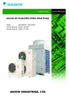


![Aneek Sanaskritik Agrasan [sept oct 16]](https://pdfs.asia/img/200x200/aneek-sanaskritik-agrasan-sept-oct-16.jpg)
