![Rectangular Tank Design [PDF]](https://pdfs.asia/img/200x200/rectangular-tank-design.jpg)
7 0 1 MB
Rectangular Tank Design Basic approach and practical tips S.Thirucheeswaran
CONTENTS ► Introduction ► Main Acceptance Criteria ► Symbols and Units ► Nomenclature ► List of parts or sections to be designed or checked ► Additional Check required for the whole tank and anchoring ► Design Input and Conditions ► General Notes and assumptions ► Types of Rectangular Tanks (Classification for design approach) ► Top plate for Rectangular Tank ► Bottom plate and Base Frame for Rectangular Tank ► Additional points for advanced design (Future) ► Practical tips ► Summary - Rectangular tank types and design references ► References ► Attachments
Rectangular tank design
2
Introduction
Guidelines and step-by-step design procedure is given below for rectangular tanks and assumptions are made for a conservative design. The design procedure is an iterative process or checking for given or assumed thickness, stiffener size and stiffener spacing. Alternatively, rigorous analysis using FEM or suitable structural design procedure can be followed.
Rectangular tank design
3
Main Acceptance Criteria 1) Calculated Stress shall be limited to ASME Code Allowable Stress [or] Actual corroded thickness provided shall not be less than required corroded plate thickness calculated using ASME Code Allowable Stress 2) Maximum deflection limited to one half of the corroded plate thickness
Symbols and Units: Kanti K Mahajan [unless specified]
Rectangular tank design
4
Nomenclature TOP EDGE STIFFENER R1 – Unit Load (Uniform on entire span of top edge stiffener)
HORIZONTAL STIIFENER
VERTICAL STIFFENER
R2 – Unit Load (Uniform on entire span of intermediate stiffener)
“l” - distance between vertical stiffeners (important parameter for shell plate thickness design) “L” – length of tank (important parameter for top edge stiffener design)
Rectangular tank design
5
Nomenclature (continued)
Primary Stiffener
Secondary Stiffener
Rectangular tank design
6
Nomenclature (continued) Load on VERTICAL STIFFENERS: UNIFORMLY INCREASING Load on SHELL (SIDE VERTICAL PLATE) : UNIFORMLY INCREASING
Load on HORIZONTAL STIFFENERS: UNIFORM ON ENTIR SPAN Load on TOP/BOTTOM PLATE (HORIZONTAL) : UNIFORM ON ENTIR SPAN
Rectangular tank design
7
List of parts or sections to be designed or checked: Shell (side plate): Thickness, stiffeners (size and spacing), weld size Top plate: Thickness, stiffeners (size and spacing), weld size Bottom plate: Thickness, stiffeners (size and spacing), weld size Base frame member sizing, weld size, supporting points Lifting lugs and other attachments
Additional Check for the whole tank and anchoring Check total tank for wind/seismic/wave/transportation etc. including anchor design.
Rectangular tank design
8
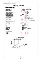
Design Input and Conditions •Tank size: Width x Height x Length, normally inside dimensions •Internal pressure, if any •Material / maximum allowable stress values •Wind loads, seismic loads, wave loads, transportation loads etc. •Calculate maximum pressure against side wall due to weight of contents (p= 0.433 H s (in psi))
Rectangular tank design
9
General Notes and assumptions: ► Design is based on open top basis, which is conservative. The effect of top plate is not considered ► If top edge stiffener of sufficient size is provided, top side of shell plate can be considered as supported on all 4 edges ► Consider either vertical stiffeners or horizontal stiffeners as primary or main stiffeners and let us call, other one “secondary stiffeners”, that are perpendicular to preliminary stiffeners ► Selection of primary stiffeners (vertical or horizontal) is based on tank size and dimensions ► Secondary stiffeners are considered to reduce plate thickness required and to transfer load to main stiffeners ► There is no simple formula or procedure to analysis or design rectangular tank with both horizontal and vertical stiffeners ► All stiffeners shall be continuous and welded at corners ► Shell plate welds shall be full penetration ► Tank design can be optimized on total weight or plate thickness and/or stiffener size ► Tank plate thickness shall be at least 3/16" (5mm) + corrosion allowance ► Suitable corrosion allowance shall be considered ► Use appropriate and consistent units ► Do not combine both vertical stiffeners and horizontal stiffeners at the same time ► If very large tank, consider internal tie-rods. Internal baffles, if any, can be considered as stiffeners. This will reduce tank plate thickness/weight.
Rectangular tank design
10
Types of Rectangular Tanks Let us classify the rectangular tanks into 9 types based on stiffeners arrangement and design procedure. Types 1 to 4 are simple in construction and design procedures are also simple. Reference [1] or reference [2] can be used directly for design of type 1 to 4 tanks. The references [1] & [2] do not give direct procedures for type 5 to 8. Hence design approaches for types 5 to 8 are explained below. Type 7 tanks can be designed using reference [6]. Type 9 Tank is designed with Tie-rods and reference [1] gives a procedure. Design of rectangular tank shell plate (side vertical plate) is critical and procedures are given below. Design procedures for top plate, bottom plate, bottom frame etc. are explained separately. Refer to sketch showing different types of tanks with stiffener arrangement commonly used.
Rectangular tank design
11
Types of Rectangular Tanks (Type-1 to 4) (Classification for design approach)
Type-1
Type-3
Type-2
Type-4
Rectangular tank design
12
Types of Rectangular Tanks (Type - 5 to 8) (Classification for design approach)
Type-5 Type-5
Type-1 Type-6
Type-1 Type-7
Type-1 Type-8
Rectangular tank design
13
Types of Rectangular Tanks (Type - 9) (Classification for design approach)
Rectangular tank design
14
Other Types of Rectangular Tanks (Not discussed here)
Rectangular tank design
15
Type-1: Open top tank without any stiffeners Shell Plate: Calculate required thickness (tr) and maximum deflection (ymax) • Use Roark’s Case 2(d), 3 edges simply supported and 1 edge free, subjected to hydro-static pressure uniformly increasing (zero at top to maximum pressure at bottom) Required thickness t r = SQRT (pb²/Sa), but not less than 3/16” Y max = p b^4 / (E ta^3), limited to (ta/2) • Acceptance criteria (stress and deflection)
Rectangular tank design
16
Type-2: Tank with Top Edge Stiffener and/or with top plate If top edge stiffener of sufficient size is provided or top plate is welded to shell plates with or without top edge stiffener, all 4 edges may be considered as supported for shell plate design and Roark’s Case 1 (e) can be used to calculate required shell plate thickness (tr) and maximum deflection (Ymax). Acceptance criteria shall be stress and deflection. • Calculate uniform load on entire span (R1) acting on the top edge stiffener. Consider top edge stiffener as a beam fixed both ends • Top edge stiffener Imin=R1 b^4 /192 E ta and select stiffener with I more than I min calculated, however the stiffener angle shall not be less than 2.5” x 2.5” x 0.25” • Recalculate shell plate thickness, deflection Roark’s Case 1(d). Select thickness (ta) • Recheck top edge stiffener sizing (step-2.2)
Rectangular tank design
17
TYPE-3: Tank with Top Edge Stiffener and one horizontal stiffener Calculate uniform load on entire span of top edge stiffener R1 & horizontal stiffener R2
• Calculate moment of Inertia required for stiffeners and select stiffener size • Recalculate shell plate thickness, deflection Roark’s Case 1(d). Select thickness (ta)
• Recheck stiffener sizing for latest plate thickness selected
Rectangular tank design
18
TYPE-4: Tank with Top Edge Stiffener and one or more vertical stiffeners • Calculate R1 and size top edge stiffener. Use length of tank “L” as stiffener length [Do not use stiffener spacing “l” as length of stiffener]
• Calculate moment of Inertia required for stiffener and select stiffener. Use height of tank as vertical stiffener length and uniformly increasing loading on the vertical stiffener
• Recalculate shell plate thickness, deflection Roark’s Case 1(d). Select thickness (ta)
• Recheck stiffener sizing for latest plate thickness selected
Rectangular tank design
19
TYPE-5: Top Tank with Top Edge Stiffener, one horizontal primary stiffener and one or more vertical secondary stiffener Same as type-3 and calculate secondary vertical stiffener size considering uniformly increasing load both ends fixed (Roark’s case 2(d) Table-8; Wa = 0 & Wl = p). Alternatively, use same size as primary horizontal stiffener without calculation
Rectangular tank design
20
TYPE-6: Tank with Top Edge Stiffener, one or more vertical primary stiffeners and one or more horizontal secondary stiffener Same as type-4 and calculate secondary horizontal stiffener size considering uniform load on entire span both ends fixed (Roark’s case 2(d) Table-8; Wa=Wl). Alternatively, use same size as primary horizontal stiffener without any calculation
Rectangular tank design
21
TYPE-7: Top Tank with Top Edge Stiffener and 2 or more horizontal stiffeners • Similar to type-3, however the loads on horizontal stiffeners are calculated using reference [6].
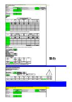
• Calculate load (uniform load on entire span) on each stiffener R1, R2, R3 etc. Refer Attachment for sample calculation.
• Calculate moment of Inertia required for each stiffener, select stiffener • Recheck plate thickness & deflection Roark’s Case 1(d). Select thickness (ta)
• Recheck stiffener sizing for latest plate thickness selected
Rectangular tank design
22
TYPE-8: Tank with Top Edge Stiffener, 2 or more horizontal primary stiffeners and one or more vertical secondary stiffener Same as Type-7 and calculate secondary vertical stiffener considering uniformly increasing load both ends fixed (Roark’s case 2(d) Table-8). Alternatively, use same size as primary stiffener without calculation.
Rectangular tank design
23
TYPE-9 Open Top Tank with Tie-rod supports (For very large rectangular tanks, internal tie-rods can be considered to reduce plate and stiffener size and weight, if permitted for service or process requirements. Internal baffles or partition plates can be considered as tie rods/stiffeners)
Rectangular tank design
24
Top plate for Rectangular Tank (common for all types of tanks) ► Design top plate, if applicable, [4 edges simply supported, uniform load over entire plate - Roark’s Case 1 (a)] Loads to be considered self weight, maintenance load, snow load etc. Use 2000 kg/m2, as a default uniformly distributed load on entire surface of top plate and add internal pressure if any. ► Provide stiffener for top plate by connecting all vertical stiffeners, as a default. This is mainly required for transfer of load from vertical stiffener, unless special stiffener arrangement is designed. ► Check bottom plate thickness for maximum un-stiffened area
Rectangular tank design
25
Bottom plate and Base Frame for Rectangular Tank (common for all types of tanks) • Provide base frame covering all 4 sides of the tank • Consider simply supported both ends for sizing the long side frame member and load half of the maximum design weight UDL (uniformly distributed along the entire length), provide same size for short side (no calculation is required for short side-conservative)
• Provide stiffeners for tank bottom plate (connecting long side members of base frame) load may be calculated (W = p x spacing) kg/mm (uniformly distributed load/unit length). Stiffener size can be of smaller than outer base frame member size
• If required, provide additional stiffeners in perpendicular direction (smaller in size than outer base frame member size) in order to reduce the bottom plate thickness.
• Check bottom plate thickness for maximum un-stiffened area - Roark case 1(a) Table-26 • Minimum thickness shall be 0.25” (6 mm) plus corrosion allowance, if entire surface of the bottom plate is supported.
Rectangular tank design
26
Base Frame (common for all types of tanks)
Rectangular tank design
27
Additional points for advanced design (Future) ► Combined effect of plate and stiffeners (limits 10 times plate thickness) ► Selection of primary stiffeners (vertical or horizontal) based on tank size and dimensions, relation between tank length-L and Height-H ► Bolted rectangular tanks, bolted top plate ► Consideration of design pressure, usually a small pressure like 0.05 bar ► Loading: seismic, transportation, wave etc. ► Top plate loading 2000 kg/sq.m ► Nozzle loading ► Lifting lugs, lifting analysis ► Spacing of horizontal stiffeners (unequal, increasing spacing from bottom to top) ► Weight estimation, optimization of weight, plate thickness, stiffener size/spacing etc. ► Types of loading UDL, uniformly increasing loading ► Welding of stiffeners to plate and end connections; Welding of plates
Rectangular tank design
28
Practical tips • Preferred type of welded joints (corner weld joining shell plates) • Stiffener arrangements • Do not extrapolate the design procedure of one type to other type without proper consideration
• Un-stiffened tanks may not be larger than 30 ft3 (0.85 m3) • Un-stiffened tank size (any side) may not exceed 3 ft (0.9 m) • For using Roark’s formula 2(d) in table 8 (both ends fixed), the tank shall have adequate stiffeners and all tank corners shall have stiffener/framed structure. Stiffeners shall be continuous and interconnected at the ends
• Do not use Roark’s formula 8(d) in table 11 (rectangular tank fixed all edges, uniformly decreasing load parallel to side b), unless stiffeners and frame are very rigid
Rectangular tank design
29
Practical tips (continued)
Rectangular tank design
30
Rectangular tank design
31
Practical tips (continued)
Rectangular tank design
32
Summary - Rectangular tank types and design references
Rectangular tank design
33
References: 1. Eugene F.Megyesy, Pressure Vessel Handbook, Pressure Vessel
Publishing Inc., 12th Edition 2001 (Check for latest edition) 2. Kanti K Mahajan, Design of Process Equipment, Pressure Vessel Handbook Publishing, Inc. Third Edition 1990 (Check for latest edition) 3. Kanti K Mahajan, A method for designing rectangular storage tanks, Chemical Engineering, March 28, 1977 pp 107-112 4. Warren C. Young, Richard G. Budynas. Roark’s Formulas for Stress & Strain, 7th Edition 5. Omer W. Blodgett, Design of welded Structures, The James F.Lincln Arc Welding Foundation, Fifteenth Printing March-1996 6. M.Starczewski, Non-Circular Pressure Vessels – Some guidance notes for designers, British Engine Technical Report 1981 Volume XIV pp 62-88 Rectangular tank design
34
Rectangular tank design
35