![S800 Controller LIF [PDF]](https://pdfs.asia/img/200x200/s800-controller-lif.jpg)
15 0 129 KB
NV BONAS MACHINERY
SERIES 800 CONTROLLER
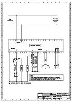
HARDWARE CONNECTIONS The following diagram shows the connections for the full interface version of the S800 controller. The interface board is accessible under the panel at the rear of the controller. P2
P3
P9
P8
P4
IO1
IO2
SW3 J1
SW4
SW1
SW2
0v
48v P1
FO1
FO2
FO3
FO3
P7
P1 P2 P3 P4 P7 P8 P9
Power connection to controller from Jacquard: 48V DC Data link to Jacquard head 1. Data link to Jacquard head 2. Serial link (RS485) to Loom. CAN link to Loom Watchdog connection from Jacquard Resolver connection to Jacquard
J1 J3 J4 J6 J7
Network (Ethernet) RJ45 connector Loom emergency stop connections Jacquard emergency stop connections Loom contactor supply Jacquard contactor connection
IO1 IO2
Loom parallel connections (inputs and outputs) Extended Loom parallel connections
FO1 FO2 FO3 FO4
Fibre optic data connection head 1 receiver Fibre optic data connection head 1 transmitter Fibre optic data connection head 2 receiver Fibre optic data connection head 2 transmitter
J4
J3
J7 J6
Note: Remove connector protection caps before installing fibre optic cables SW1 SW2 SW3 SW4
Controller input source/sink selection Input/output voltage selection Controller output source/sink selection CAN link termination
NOTE: ON SERIAL COMMUNICATION LOOMS, THE INTERFACE CONNECTIONS ARE REDUCED VERSION 1.00
Page 7