![Service Manual For CHEM 5X - V2012.01.01 [PDF]](https://pdfs.asia/img/200x200/service-manual-for-chem-5x-v20120101.jpg)
15 0 2 MB
Service Manual
For
Semi-Automated Clinical Chemistry Analyzer
Document Version: 2012.01.01 Last Updated: February 20, 2013
Service Manual
CHEM-5 X
Foreword This manual is organized in a progressive sequence for easy study and reference. It is an instructional aide to provide a reference for easy servicing and maintenance of the analyzer. It contains detailed description of the analyzer features, specifications, PCB layouts, wiring diagrams, trouble shooting and replacement procedures. Use of this manual along with proper training will ensure better serviceability, maintenance and trouble free analyzer operation with optimum performance. Before servicing the analyzer, service engineer should: 1. Read and understand this manual. 2. Be trained by authorized person. 3. Be familiar with the operation of the analyzer.
NOTE: Keep this manual in an easily accessible place.
II
Service Manual
CHEM-5 X
Legal Information All rights are reserved by manufacturer of this product. Manufacturer is the copyright owner of this document. The contents of this document are subject to change without prior notice and without legal obligation. This document and the information herein are provided for the sole use of the intended recipient(s) and for information purposes only. This document contains contents which are the confidential and proprietary information of the manufacturer. This document cannot be modified, reproduced, translated or transmitted in any form or by any means for any purpose, without prior written permission from the manufacturer. No part of this document can be copied or reprinted, in whole or in part, without prior written permission from the manufacturer.
III
Service Manual
CHEM-5 X
CONTENTS 1. OVERVIEW OF ANALYZER....................................................................................... 1-1 1.1. INTRODUCTION ................................................................................................. 1-1 1.2. ANALYZER VIEW ................................................................................................ 1-2 2. SAFETY ...................................................................................................................... 2-1 3. ANALYZER FEATURES ............................................................................................ 3-1 3.1. HARDWARE SPECIFICATIONS ......................................................................... 3-1 3.2. SOFTWARE SPECIFICATIONS .......................................................................... 3-2 3.3. KEYBOARD DESCRIPTION ............................................................................... 3-4 3.4. ASPIRATION SWITCH ........................................................................................ 3-6 4. INSTALLATION .......................................................................................................... 4-1 4.1. INSPECTION ....................................................................................................... 4-1 4.2. UNPACKING ....................................................................................................... 4-1 4.3. INSTALLATION REQUIREMENTS ..................................................................... 4-2 4.4. ELECTRICAL REQUIREMENTS ......................................................................... 4-2 4.5. INSTALLATION PROCEDURE ........................................................................... 4-2 4.6. PRINTER HOUSING AND PRINTER PAPER INSTALLATION........................... 4-3 4.6.1. INTERNAL PRINTER ............................................................................................... 4-3 4.6.2. EXTERNAL PRINTER .............................................................................................. 4-3 4.6.3. PC COMMUNICATION............................................................................................. 4-4
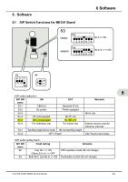
4.7. EXTERNAL KEYBOARD INSTALLATION........................................................... 4-4 5. BLOCK DIAGRAM ..................................................................................................... 5-1 6. FUNCTIONAL DESCRIPTION OF PCB ..................................................................... 6-1 6.1. POWER SUPPLY SECTION ............................................................................... 6-4 6.2. CONTROL LOGIC SECTION .............................................................................. 6-7 6.3. MOTOR CONTROL AND MEMORY ................................................................. 6-10 6.4. PHOTOMETRIC UNIT ....................................................................................... 6-12 6.5. USB PCB ........................................................................................................... 6-14 6.6. PRINTER ........................................................................................................... 6-16 6.7. KEYPAD AND DISPLAY SECTION................................................................... 6-16 7. WIRING DIAGRAM ..................................................................................................... 7-1 8. TESTING AND PARAMETERS .................................................................................. 8-1 8.1. TESTING OF SMPS ............................................................................................ 8-1 8.2. TESTING OF CPU PCB ...................................................................................... 8-2 8.3. POWER ON HARDWARE TEST ......................................................................... 8-2 8.3.1. HARDWARE TEST................................................................................................... 8-2
8.4. SETTING PARAMETERS.................................................................................... 8-4 8.4.1. SYSTEM SETUP ...................................................................................................... 8-4 8.4.2. SETTING THE DATE ............................................................................................... 8-4 8.4.3. SETTING THE TIME ................................................................................................ 8-5 8.4.4. SETTING THE DATA OUTPUT MODE .................................................................... 8-6 8.4.5. LAB INFORMATION ................................................................................................. 8-6 8.4.6. BLANK DEDUCTION................................................................................................ 8-7 8.4.7. AIR PURGE .............................................................................................................. 8-7
IV
Service Manual
CHEM-5 X
8.5. ADJUSTMENT AND CALIBRATION ................................................................... 8-8 8.5.1. OFFSET AND GAIN CALIBRATION OF PHOTOMETER ......................................... 8-8 8.5.2. ENTERING OFFSET ADJUSTMENT DATA MANUALLY ......................................... 8-8 8.5.3. ADJUSTING LCD DISPLAY BRIGHTNESS ............................................................. 8-8 8.5.4. TEMP CALIBRATION (IN NORMAL CONDITION) ................................................... 8-8 8.5.5. PUMP CALIBRATION ............................................................................................ 8-11
9. MAINTENANCE .......................................................................................................... 9-1 9.1. DAILY MAINTENANCE ....................................................................................... 9-1 9.2. QUATERLY MAINTENANCE .............................................................................. 9-1 9.3. REPLACEMENT OF TUBING ............................................................................. 9-2 9.3.1. ASPIRATION TUBE REPLACEMENT ...................................................................... 9-2 9.3.2. REPLACEMENT OF PERISTALTIC PUMP TUBINGS ............................................. 9-4
9.4. REPLACEMENT OF LAMP ASSEMBLY ............................................................. 9-5 9.5. REPLACEMENT OF PRINTER PAPER .............................................................. 9-7 10. TROUBLE SHOOTING GUIDE............................................................................... 10-1 10.1. TROUBLESHOOTING SECTION .................................................................... 10-5 11. SPARE PARTS ....................................................................................................... 11-1 11.1. SPARES DETAILS AND ORDERING INFORMATION.................................... 11-1 11.2. LIST OF CONSUMABLES ............................................................................... 11-4 12. APPENDIX .............................................................................................................. 12-1 12.1. REVISION HISTORY ....................................................................................... 12-1
V
Service Manual
CHEM-5 X
1. OVERVIEW OF ANALYZER 1.1. INTRODUCTION The CHEM5X (hereafter referred as an analyzer) is a low cost, low power, compact, high performance 16-bit micro controller based Biochemistry analyzer, which is used for Routine Chemistries, Electrolytes, Hormones and Drug tests. There are 9 modes of operation. Programming, Reading and Reporting operations are user friendly. The analyzer is provided with memory for storage of Quality Control Data, Reagent Blank Absorbance, Factor, and Non-linear Calibration Data and up to last 1000 results with Patient ID. Operation is through a non-tactile Keyboard with quick shift from one function to another without going through complex sequential operations. The analyzer is provided with a 240 X 64 dots backlit liquid crystal display with alphanumeric and graphic capabilities. A Patient ID wise or Date wise or Patient ID with Date wise collated report can be generated upon request. Exhaustive Quality Control Data at 2 levels, for any of the tests can be stored and printed. The software is complete with the device diagnostic self-test function capable of providing timely flag / error messages related to Test results or analyzer malfunctioning. The State-of-the-Art features, advanced optics, versatile analytical capabilities and economy of 33μl flow cell make it the analyzer of choice for all laboratories.. This analyzer is intended to be used:
For In-vitro quantitative and qualitative determination of wide range of analytes in body fluids as mentioned above.
By the trained personnel in controlled environment and continuously monitored operation.
1-1
Service Manual
CHEM-5 X
1.2. ANALYZER VIEW
PHOTOMETER COVER
PRINTER COVER
DISPLAY
KEYPAD
ASPIRATION TUBE
ASPIRATION SWITCH
1-2
Service Manual
CHEM-5 X
ON/OFF SWITCH
INCUBATOR CONNECTOR
PERISTALTIC PUMP COVER
PC INTERFACE PORT
EXTERNAL USB PRINTER PORT
EXTERNAL PC/AT KEYBOARD PORT
DC INPUT SUPPLY
SERIAL NUMBER PLATE
1-3
Service Manual
CHEM-5 X
2. SAFETY Operator’s and Service personnel safety is a primary concern. This section provides safety information about analyzer. Use this product properly and safely to prevent injuries and or damage to property. User must read these safety precautions before installation/use and follow the directions.
Only qualified personnel should use the analyzer.
While operating, maintaining, servicing or repairing the analyzer, follow all the procedures described in this manual.
Always ensure that mains switch is OFF while connecting or removing or servicing the analyzer.
Observe all WARNINGS and CAUTIONS posted on the system or described in this manual.
Avoid contact with all electrical circuits of analyzer; observe CAUTIONS posted on the analyzer.
Never use substitute parts on the analyzer or modify it in any way.
Analyzer should not be exposed to rain or water in any form. Avoid operating on an inclined surface or any form of shock and vibration to the analyzer.
During the operation photometric lamp becomes extremely hot. DO NOT look directly into the light path of the lamp when it is ON. DO NOT touch the lamp when it is ON.
If the lamp needs to be changed, always switch off the lamp by switching off the analyzer and then wait for minimum 10-minutes, until lamp has cooled down.
Auxiliary 18Vdc supply available on the back side of Instrument (Incubator connector) for optional incubator only. Do not connect any other equipment to this connector
Avoid using dangerous flammable material around the analyzer. Fire or explosion may be caused by ignition.
Avoid areas that are adversely affected by atmospheric pressure, temperature, humidity, ventilation, sunlight, dust and air containing salt, sulfur, etc.
Operator is responsible for taking all necessary precautions against hazards associated with the use of clinical laboratory chemicals. Specific recommendations for each reagent used with the analyzer are normally found on the manufacturer’s package inserts or on product information sheets for each chemical. Wipe up any reagent spillage on the analyzer immediately.
2-1
Service Manual
CHEM-5 X
Pay attention not to exceed time and volume necessary for diagnosis. Keep monitoring the behavior of whole system in order to detect any malfunction.
Take immediate corrective measures including shutdown of operation when any malfunction is detected in the analyzer.
In the event of trouble, do not play with the analyzer and leave any repair work to an authorized expert. Caution: NEVER OPERATE ON A WET OR DAMP SURFACE.
2-2
Service Manual
CHEM-5 X
3. ANALYZER FEATURES 3.1. HARDWARE SPECIFICATIONS 1
SYSTEM TYPE
Open, Flow cell.
2
MEASUREMENT PRINCIPLE
Colorimetry (Rate/End Point)
3
APPLICABLE ANALYTES
Photometric assays – Substrates, Enzymes, Lipid, Protein, Sugar, Inorganic Substances
4
SETUP
Bench top.
5
LIGHTSOURCE
Quartz Halogen Lamp, 12V, 20 Watts.
6
PHOTOMETRIC RANGE
0 ~ 2.5 O.D. (Range 340~630nm) Resolution 0.0001.
7
OPTICS
6 wavelength static photometric group with following interference filters: 340, 405, 505, 546, 578, 630 nm.
8
DETECTORS
6 UV / VIS Silicon photodiodes.
9
CUVETTE
Unique triple cuvette system: 33 µl flow cell 10 mm rectangular polystyrene cuvette
10
THERMOSTAT
Peltier temperature control for 25, 30 and 37°C ± 0.1° C.
11
FLOWCELL VOLUME
33 µl
12
SAMPLE ASPIRATION
By means of a peristaltic pump, Aspiration Volume programmable from 350µl to 999µl.
13
PRECISION
Better than 1% CV.
14
KEYBOARD
Rugged water proof, , non-tactile legend membrane panel 25 keys
15
SMPS
EXTERNAL(18/24V DC; 70/100W)
16
PRINTER
High resolution, 384 dots per line, thermal type with full graphics facility and option for connecting external USB printer
17
DISPLAY:
High-resolution Graphics LCD 240x64 dots, with backlit. View area 134mm x 40 mm.
18
INTERFACES
USB B type port for host computer and USB A type port for External USB DeskJet Printer. External PC/AT keyboard.
19
PROCESSOR:
16-bit with 384KB Flash Memory
20
MEMORY:
2MB Serial Flash and 2MB EEPROM
21
REAL TIME CLOCK:
Built in.
22
REPLACEABLE BATTERY ON PCB:
Lithium Battery CR2032 (3V)
23
WASTE COLLECTION
Waste collected in closed container.
24
INCUBATOR:
Optional external incubator.
25
OPERATING TEMPERATURE
20 – 40 Degree Celsius
3-1
Service Manual
CHEM-5 X
26
STORAGE TEMPERATURE
-10 to + 50 Degree Celsius.
27
HUMIDITY
Max.80% RH, non-condensing.
28
MAINS SUPPLY
115/230V AC (±10%), 50/60 Hz (converted to 18~24V DC using External Universal SMPS adapter, maxi. power 70~100W).
29
SIZE:
438 (L) x 295 (W) x 184 (H) mm.
30
WEIGHT:
Approximately 5 kg.
NOTE:
Above specifications subject to change without prior notice.
3.2. SOFTWARE SPECIFICATIONS
9 analytical modes of operation:
1-point Linear 2-point Linear Rate A Linear 1-point Non-Linear (Cubic Spline / Point to point / Logit Log) 2-point Non-Linear (Cubic Spline / Point to point / Logit Log) Rate A Non-Linear (Cubic Spline / Point to point / Logit Log) 1-point Sample Blank Linear 1-point Sample Blank Non-linear (Cubic Spline / point to point / Logit Log)
Absorbance
150 totally “OPEN” test programs selectable through keypad
Parameters can be viewed, edited, and printed
Facility to memorize Reagent Blank ABS., Sample Blank ABS., Standard ABS., Factor, Non-linear curve.
Patient report for last 1000 results stored in memory are obtained by
Date I.D Both by Date and I.D
Graphic presentation of Non Linear calibration curves
QC (QC Data available for two controls per test)
3-2
Service Manual
CHEM-5 X
Daily QC Monthly QC
Rate calculation by least square regression method.
Automatic zeroing of Water OD during Run Test.
Total reaction time: Selectable delay time between 5 seconds to 999 seconds. Selectable read time between 5 seconds to 999 seconds.
Non-linear calibration (6 standards).
On-line reagent stability check.
Substrate depletion / Non-linearity check.
In built reaction non-linearity check.
Monochromatic as well as bichromatic measurements possible.
Calibration of peristaltic pump.
On-line display of cuvette temperature.
On-line help.
Self-diagnostics.
Help messages on erroneous entry.
Reports can be printed on USB Printer or Thermal Printer by either using PRINT key or Automatic.
3-3
Service Manual
CHEM-5 X
3.3. KEYBOARD DESCRIPTION
KEY
DESCRIPTION These are multi-function keys. Each key is used for entering a number seen on the key, and three alphabets in upper and lowercase. E.g. The numeric key ‘1’ is used to select or enter an alphabet or the number ‘1’ in the sequence: ‘A’, ‘B’, ‘C’, ’a’, ’b’, ’c’, ‘1’ following every press. This is a dual function Key. It is used as key to save changes in parameters. It is used as key when entering numerical parameters. This is a dual function Key. It is used as key to reject changes in parameters value or to skip aspiration of analytes. It is used as key while entering numerical parameters. It is used to advance the thermal printer paper roll by few lines and is operational in most of the menus.
This key is a multi-purpose key used for different functions and different screens.
3-4
Service Manual
CHEM-5 X For Linear test, CALIB. Key is used when factor is to be calculated by running sample as standard. For nonlinear test it is used to calibrate curve. This key is used to enter the negative sign. This key is also used as READ key to take reading from Rectangular Polystyrene in place of flow cell, avoiding use of ASP switch. This key is used to return to the previous screen.
This key is used as key to cancel a typed character.
This key is used to display help menu.
This key is used to reset the instrument without resetting the memory. When this key is pressed the instrument stops any test that it is performing and goes back to the starting mode. This key is used to print data on selected Printer (USB Printer or Thermal Printer or Both).
These four keys with arrows are used to bring the cursor to the required position on the screen. Enter:-This key is used to select a chemistry, to display test parameters, to run the test or for QC reports.
3-5
Service Manual
CHEM-5 X
3.4. ASPIRATION SWITCH The Switch Actuator is located at right hand side below the aspiration tube which is provided for aspiration of liquid into the flow cell and for washing flow cell.
3-6
Service Manual
CHEM-5 X
4. INSTALLATION 4.1. INSPECTION The analyzer is tested before shipment and is packed carefully to prevent any shipping damage. It is user’s responsibility to inspect all cartons upon arrival and notify the carrier of any apparent damage. Follow the steps described in the paragraphs below to install the analyzer.
4.2. UNPACKING The main unit and accessories are packed in single carton. Other additional accessories such as power cord may be packed in another carton. The representative is responsible for unpacking, installing and initial setting up of the analyzer. Serial Number
Item Code
Description
Quantity
1
110082
STANDARD ACCESSOIRES
1 SET
2
110348
DUST COVER
1 NOS
3
110347
RECTANGULAR POLYSTYRENE MICRO CUVETTE
5 NOS
4
112458
OPERATOR MANUAL for CHEM5X (Version 2012.01.01)
1 NOS
5
106046
POWER CORD (3 PIN) 6A, 250V, LENGTH 1.5 METER, BLACK COLOR, PLUG AS PER IS-6538, CABLE AS PER IS-694, SOCKET IEC APPROVED AS PER SAMPLE APPRO
1 NOS
6
110309
THERMAL PRINTER PAPER ROLL (57MM X 30M)
1 KIT
7
102948
AC POWER ADAPTER (OP:18 VDC:70W) PPS70A-16 L TYPE
1 NOS
8
110326
ALLEN KEY SIZE: 2.5 MM
1 NOS
9
110035
ASSEMBLY WASTE BOTTLE
1 NOS
10
103936
P.M. KIT
1 NOS
11
110018
ASSEMBLY LAMP
1 NOS
12
110353
SYRINGE 5 ML (CAT NO 300850 MAKE B-D)
1 NOS
13
110354
TUBING PVC (ID 2.8 MM, OD 4.3 MM)
0.55 M
14
111213
TUBE TEFLON 0.75MM X 1.5 MM (442-5409-4)
0.21 M
15
110194
TUBE TEFLON (ID 1 MM, OD 2 MM, PTFE - M0004)
0.027 M
16
112546
PERISTALTIC TUBE ASSEMBLY
1 NO
17
110356
SILICON TUBING (ID 2 MM, OD 4 MM) (IMPORTED)
0.36 M
18
110355
TUBE SILICON (ID-0.8 MM, OD-2.4 MM)
0.012 M
NOTE: Please refer to dispatch note for detailed checklist.
4-1
Service Manual
CHEM-5 X
4.3. INSTALLATION REQUIREMENTS The proper location is an important consideration; an improper location can lead to malfunction of the analyzer. Please follow our environmental and electrical suggestions to ensure the accuracy and precision of analyzer and to maintain high level of safety for your personnel. Since the analyzer is comparatively smaller, it can be comfortably accommodated on any standard sized table. Remember that minimum 30 cm. space is maintained between the rear panel and the wall to allow for heat dissipation. The waste bottle should be placed on the same level or below the level of analyzer. Please ensure while taking any electrical measurement, the multimeter used must have been calibrated and should possess valid calibration identification traceable to National/International standard. Also ensure that the power supply should be placed near to the analyzer in such a way that ON/OFF switch is easily accessible to the user. This will help the user to switch OFF the instrument immediately in case malfunctioning is detected. PROBLEM resulting from the relocation of the analyzer done by unauthorized service representative are not covered under warranty.
4.4. ELECTRICAL REQUIREMENTS Voltage and Frequency
Single phase continuous stabilized AC 115/230 volts ± 10%, 50 / 60 Hz.
Grounding
Perfect earthing must be provided at power source with all applicable local requirement (A grounded, power plug only should be used). The Voltage between earth and neutral should not exceed more than 5 V.
Plug Points
3 No. of 5 Amps outlet and 2 No. of 5 Amp sockets should be available near the mounting desks. (Normally only one socket is required per analyzer and 2 extra sockets are recommended for using any measuring equipment and engineering tool if required while servicing). Failure to properly ground the analyzer bypasses important safety features and may result in an electrical hazard. Heavy duty electrical devices like Air-conditioners, Refrigerators, Oven, Centrifuge etc., should not be operated on the same electrical lines as the analyzer. The mains connection should be easily accessible, for emergency switch off.
4.5. INSTALLATION PROCEDURE 1. Unpack the accessory box. 2. Remove the waste bottle and place it on the table. 3. The Analyzer comes equipped with an external AC power adapter and one three/two pin power cord (with earth terminal) for external AC power adapter.
4-2
Service Manual
CHEM-5 X
4. Proper use of the appropriate power cord assures adequate grounding for the system. Failure to properly ground the analyzer bypasses important safety features and may result in an electrical hazard. 5. Connect the 3/2 pin cord (with earth terminal) of the external SMPS to the mains socket and check the output of the SMPS, it should be 18~24V DC ± 1V DC. 6. Connect the Peristaltic Pump tubing correctly and place the end of the peristaltic pump tubing coming out of the analyzer into the waste bottle provided for collecting the Waste.
4.6. PRINTER HOUSING AND PRINTER PAPER INSTALLATION 4.6.1. INTERNAL PRINTER There is a Thermal printer mounted inside the cabinet. It is extremely low noise printer. The non-presence/improper installation (printer lever is not pressed downward) of the thermal paper is detected and it is alarmed by 4 continuous beeps. Refer below Figure 1 for proper routing of Thermal Printer Paper roll.
NOTE: The thermal paper used must match the specification of the original one, since the calibration of the working temperature is optimized for that kind of paper. Failure to use proper quality of paper may permanently damage the printer.
4.6.2. EXTERNAL PRINTER 1. Switch off the analyzer before connecting printer. 2. HP DeskJet USB Printer can be attached to the analyzer to print reports, graphs etc. 3. USB A Type connector is provided at the rear of the analyzer. Connect the printer cable to this port before switching ON the analyzer.
4-3
Service Manual
CHEM-5 X
4.6.3. PC COMMUNICATION NOTE: USB Connectivity to PC requires operating system 2000/XP or above.
4.7. EXTERNAL KEYBOARD INSTALLATION Switch off the analyzer before connecting PS2 keyboard. Then connect to the port provided at the rear of the analyzer.
4-4
Service Manual
CHEM-5 X
5. BLOCK DIAGRAM
The major blocks of the Chem-5 x consists of CPU PCB, thermal printer, external DeskJet printer (external printer can also be connected) Photometer, Keypad and liquid crystal display (LCD), Peltier Assembly, Peristaltic Pump and External keyboard which can be connected to the analyzer. Soft key functions are designed in such a way that it operates with single touch with quick shift from one function to another without going through complex sequential operations. The LCD is a 240x64 dots, LED backlight display with alphanumeric and graphic capabilities with backlit feature which enables the user to read in case of less ambient light. This is most sensitive device to get damaged, which require careful handling, which is interfaced with keypad using a interface card. External keyboard can be connected to the analyzer using PS/2 connector provided on the rear of the analyzer.
5-1
Service Manual
CHEM-5 X
Photometer is a device to measure the intensity of the light. Where the absorbance of the radiation from the colored substances are measured by means of photodiode. It can serve 8 different wavelengths. The filter defines the wavelengths. CPU PCB as the name suggests is the heart of the analyzer, which controls all the hardware & software functions of the analyzer. Refer the details of main board in the operation section.
5-2
Service Manual
CHEM-5 X
6. FUNCTIONAL DESCRIPTION OF PCB As shown in block diagram analyzer CPU PCB is the heart of this analyzer. This CPU PCB gives necessary commands and controls the operation of other peripheral such as Keyboard, LCD, Printer and Photometer. Major blocks are explained below.
Block Diagram of CHEM 5X
6-1
Service Manual
CHEM-5 X
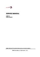
CPU PCB COMPONENT LAYOUT
6-2
Service Manual
CHEM-5 X
6-3
Service Manual
CHEM-5 X
6.1. POWER SUPPLY SECTION Instrument is operated at 115-230 V AC +/- 10% 50/60Hz power supply which, acts as input for the internal devices. This instrument uses three power supply sections designed to provide power to electronic circuit, lamp & photometer and the thermal printer. Power Supply External SMPS provides +18/24 V DC, then the following Voltages are generated by the Power distribution Board, +5V, +12 V DC & +5V, -5 V for analog section. +5 V DC, +12 V DC is given as input to the main board (which generates + 3.3 V DC for microprocessor and other logic ICs.) + 5 V & -5 V DC isolated supply for photometer and ADC. +12 V DC to motor and Incubator. Any defect in the section will lead to any of the following problem(s): 1. Lamp/Fan voltage fluctuation 2. Lamp/Fan not working. 3. Printer not working. 4. Backlight of LCD is OFF. 5. Analyzer is not getting switched ON. Action to be taken
Check ON/OFF switch; any loose connection of cable assy.
Check 18V DC ±1V DC; if NOT OK then replace power adaptor.
Check 5V, 12V & ±5V supply (±5%); if not OK then replace DC-DC Power Supply PCB assembly
.
6-4
Service Manual
CHEM-5 X
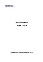
POWER SUPPLY COMPONENT LAYOUT
6-5
Service Manual
CHEM-5 X
POWER SUPPLY SCHEMATIC DIAGRAM
6-6
Service Manual
CHEM-5 X
6.2. CONTROL LOGIC SECTION The operations for controlling the instrument are performed by the CPU PCB. This section is provided with MB90F334A microcontroller, 2MB of EEPROMs, a serial interface RS 232C for interfacing Thermal Printer. The logic is all in CMOS technology to guarantee low consumption and high reliability. The RTC is provided with 3V coin battery. Any defect in the section will lead to any of the following problem(s): 1. Communication is not taking place between processor and peripheral devices.
6-7
Service Manual
CHEM-5 X
2. External printer is not working. 3. Calibration data is not getting stored. Action to be taken:
Replace CPU PCB.
.
6-8
Service Manual
CHEM-5 X
SCHEMATIC – CONTROL LOGIC SECTION
6-9
Service Manual
CHEM-5 X
6.3. MOTOR CONTROL AND MEMORY This section controls the motion of motor using IC A3979. It is a DMOS Fully Integrated Stepper Motor driver features a non-dissipative over current protection on the high side Power MOSFETs and thermal realized in Multi-power-BCD technology. It includes a constant off time PWM current controller. When the voltage drop across the sense resistor becomes greater than the voltage at the reference input (VREFA or VREFB) the sense comparator triggers the mono stable switching the motor off. When, the mono stable times out the motor will again turn on. To store different types of data three 1024K bits IC 24c1024 are used to store.IC U4 is used for chemistry parameters, patient reports, values of standards and blank for non-linear chemistry, for quality control data and U6 is used for default parameter. IC 1338Z is a Real Time Clock plus RAM. The function includes a nonvolatile time of day, calendar. The time of day and memory are maintained even in the absence of power. Any defect in the section will lead to any of the following problem(s) 1. Water, standard, solution is not getting aspirated after pressing ASP switch. 2. Motor is not running or not stopping. 3. Chemistry parameters are not stored. 4. Patient report or quality control data is not stored. 5. Date and time is not correct. 6. Default parameters are incorrect 7. Quality Control Data is not stored Action to be taken •
For defect number 1 and 2, replace CPU PCB.
•
For defect number 3 and 4, replace U4.
•
For defect number 5, replace U16.
•
For defect number 6, replace U6.
•
For defect number 7, replace U6
6-10
Service Manual
CHEM-5 X
MOTOR CONTROL AND MEMORY SCHEMATIC DIAGRAM
6-11
Service Manual
CHEM-5 X
6.4. PHOTOMETRIC UNIT It is one of the major blocks of the instrument & it contains 8 different narrowband optical interference filters of wavelengths 340, 405, 450, 505, 546, 578, 600, and 670 nm for specific chemistry tests. When ray of light is passed through the reaction cell part of it gets absorbed by the reaction solution and then passes through the filter. This filtered light is detected by photodiodes, which is amplified, and send to the multiplexer CD 4051which selects the one signal and communicates to processor for further processing. Any defect in the section will lead to any of the following problem(s): 1. Absorbance values not displayed. Action to be taken:
Check that the flowcell is clean and scratch free.
Replace Photometer PCB.
PHOTOMETER COMPONENT LAYOUT SCHEMATIC – PHOTOMETRIC UNIT
.
6-12
Service Manual
CHEM-5 X
SCHEMATIC – PHOTOMETRIC UNIT
6-13
Service Manual
CHEM-5 X
6.5. USB PCB USB PCB having USB ‘A’ type connection for external USB printer (selected models only). USB ‘B’ type connection for PC communication. IC CP2102 is used to convert the serial data (Result) being dumped by the microcontroller to the PC in USB format. Any defect in the section will lead to any of the following problem(s): 1. USB printer not printing instrument chemistry test results. 2. Communication between PC and USB not established. Action to be taken:
Check USB A-B cable and if found faulty, replace with new.
Check CP2102 driver in PC.
Check software communication settings in PC.
Replace USB PCB assembly.
USB PCB COMPONENT LAYOUT
6-14
Service Manual
CHEM-5 X
USB PCB SCHEMATIC DIAGRAM
6-15
Service Manual
CHEM-5 X
6.6. PRINTER The printer is 40 column graphic printers, able to give a very high printing quality, high speed and a considerable noiselessness on thermal paper without having to move the printing head.
6.7. KEYPAD AND DISPLAY SECTION The liquid crystal graphic with 240x64 dots, with alphanumeric and graphic capability. A 25 key membrane tactile keyboard is provided.
6-16
Service Manual
CHEM-5 X
7. WIRING DIAGRAM
7-1
Service Manual
CHEM-5 X
8. TESTING AND PARAMETERS The instrument assemblies are factory adjusted and does not require any fieldtesting, adjustment or settings. It is advisable not to change setting unless necessary. If it is necessary, the testing, adjustment or setting must be carried out by trained and authorized personnel only.
8.1. TESTING OF SMPS 1. Check the mains power supply. It should be within 115/230V AC, 50/60Hz, ±10%. 2. .Connect one end of 2/3-pin power cord to the External SMPS and the output of SMPS to the DC input of the Analyzer. Check the input/outputs of the Power Distribution Board using a calibrated Multimeter, it should be as follows: a. Input: Pin No(On J1 connector)
Normal Condition
1 2
Description
Test Point no.
+18/24V
Input DC Supply
TP5
GND
Digital Ground
TP6
Pin No(On J2 connector)
Normal Condition
Description
Test Point no.
1
+5V
Vcc
TP1,TP4
2
GND
Digital Ground
TP6
3
+12V
Supply to MOTOR
TP2
4
GND
Digital ground
TP6
5
+5V
To Thermal printer
TP7
6
GND
Digital ground
TP6
7
+5Va
+Vcc analog
TP8
8
GNDa
Analog GND
TP3
9
-5Va
-Vcc analog
TP9
10
+12V
Supply to FAN
TP2
11
GND
Digital Ground
TP6
12
+12 V
Supply to LAMP
TP2
13
GND
Digital ground
TP6
14
NC
Not Connected
-
b. Output:
8-1
Service Manual
CHEM-5 X
8.2. TESTING OF CPU PCB Give supply at J1 connector from Power Supply PCB and measure voltages at various test points with respect to common ground point using a calibrated Multimeter. Test Point
Normal Condition
TP details
TP1
0V
GND
TP19
+5V
Vcc
TP20
+12VR
Supply to Motor
TP22
-5 VANA
-Vcc analog
TP23
+5 VANA
Vcc analog
TP24
+3.3V
Vcc to µC
8.3. POWER ON HARDWARE TEST 1. Switch ON the analyzer by pressing the ON/OFF switch provided on the SMPS adaptor. 2. After switching ‘ON’ the analyzer, ERBA MANNHEIM logo is displayed and analyzer will do self-diagnostic it will automatically check all the important devices and will show the status on display. 3. If all the hardware tests are OK then the following display appears during the self-diagnostic test. 4. This is routine test that will be performed every time the analyzer is switched ON.
5. If any of the parameter is not ok, then the following message will be displayed PROCEED…. Press YES key if you want to proceed. 6. If all the hardware tests are OK then the Home Screen will be displayed.
8.3.1. HARDWARE TEST 1. Press numeric key < 4 > and go to maintenance in the Home screen and the following screen is displayed. 2. Check the temperature of the flow cell press any of the numeric keys < 0-3 > and corresponding temperature is attained in the flow cell. 3. Temp. of the flow cell will be displayed.
8-2
Service Manual
CHEM-5 X
4. Press < > > key to display the next page.
PUMP CALIBRATION: Aspirate 1000µL of water by pressing aspirate switch to start and stop. The calibrated count is displayed on the screen. Note: Perform WASH with 3ml DI Water to fill the tube up to Peristaltic pump before proceeding for Pump Calibration. LOAD DEFAULT PARAMETERS: Press to download default parameters from the memory.
Press key to go to the next page or < ← > to go back to the previous page.
Press numeric keys to get PRE CHANNEL and LOG CHANNEL readings for 6 filters. Press < → > key to display the next page.
8-3
Service Manual
CHEM-5 X
THERMAL PRINTER TEST MENU: Test Print for thermal printer. Press < → > key to display the next page. KEYPAD CHECK MENU: Test all the 25 keys in this menu.
8.4. SETTING PARAMETERS 8.4.1. SYSTEM SETUP The system setup option allows the user to view, edit and print the system date, time and the data output mode. The “System Setup” screen is as follows:
The numeric keys 1, 2, 3, 4 and 5 are used to set the date, time, data output mode, laboratory information, and Blank Deduction option respectively.
8.4.2. SETTING THE DATE The analyzer incorporates a built-in calendar function, which is maintained by a battery, and once set, the Date and Time will be printed every time the analyzer prints result data on the printer. Press numeric key '1' and the following screen appears:
8-4
Service Manual
CHEM-5 X
The cursor is positioned on the DATE field on the SYSTEM SETUP: DATE screen. Enter an appropriate data in the following format: DAY : Enter a day from 01 to 31 MONTH : Enter a month from 01 to 12 YEAR : The last 2 digits of any year from 00 to 99 After appropriate entry is made, press the key to save date and return to the System Setup screen or press < PREV. > to quit without saving and return to the System Setup screen. NOTE: If the date is entered wrong, the user will be prompted with the message, "INVALID DATE. PLEASE ENTER AGAIN".
8.4.3. SETTING THE TIME Choose the option '2' from the SYSTEM SETUP menu and SET TIME. The display appears. The cursor is positioned on the TIME field on the SYSTEM SETUP: TIME screen. Enter an appropriate time in the format as stated below.
HOUR: Enter an hour from 00 to 23. MINUTE: Enter minutes from 00 to 59. SECONDS: Enter seconds from 00 to 59. Each entry is separated by a ‘:’ sign, which appears automatically after the entry of the 2nd digit. After appropriate entry is made, press the key to save and return to the System Setup screen or press to quit without saving and go back to the System Setup screen. NOTE: If the Time is entered wrong, the user will be prompted with the message, “INVALID TIME. PLEASE ENTER AGAIN”.
8-5
Service Manual
CHEM-5 X
8.4.4. SETTING THE DATA OUTPUT MODE Choose numeric key 3 on the SYSTEM SETUP screen to select the data output mode.
Press or to select or deselect Thermal printer or USB Printer for auto print options or printout on Thermal printer/USB Printer after pressing key. Tick mark will be displayed in front of selected option & it will disappear if any option deselected.
8.4.5. LAB INFORMATION Choose the option 4 from the SYSTEM SETUP screen and the following screen appears:
The user can enter laboratory information (25 characters each on 5 lines) with external PC/AT keyboard or the analyzer keypad. This is stored in the memory. Example of Using analyzer Keypad to Enter Lab information: Item
Description Each key can be used for entering three alphabets in upper and lowercase. And followed by the number seen on the key, e.g. ‘A’, ‘B’, ‘C’, ’a’, ’b’, ’c’, ‘1’ to ‘Y’, ’Z’, ’y’, ’z’, ’-‘, ’9’ ‘*’, ', '(', ')', '.', '0'
8-6
Service Manual
CHEM-5 X
The laboratory information is printed as header in Thermal and External Printouts.
8.4.6. BLANK DEDUCTION If 1-POINT/SMP-BK option is selected then Reagent Blank O. D. will be subtracted from all the test O. D. for 1 point and sample Blank modes, all modes of kinetic and 2 – point assays as well as for One point mode. If 2-POINT/RATE A option is selected then Blank O. D. will be subtracted for all modes of kinetic and 2 – point assays. The options can be selected or de-selected by pressing or respectively.
8.4.7. AIR PURGE Choose the option ‘6’ < AIR PURGE> from the SYSTEM SETUP screen and the following screen appears:
The user can select or deselect Air Purge option from this menu. For Rate A and Two Point mode, Air Purge must be enabled if aspiration volume is less than 450μl. However, Air Purge is optional if the aspiration volume value is between 450 – 999 µl. If Air Purge is enabled extra 150 μl air is aspirated after displaying the result. If Air Purge is disabled, extra 150 μl air will not be aspirated
8-7
Service Manual
CHEM-5 X
8.5. ADJUSTMENT AND CALIBRATION 8.5.1. OFFSET AND GAIN CALIBRATION OF PHOTOMETER 1. Go to the ‘Maintenance’ menu. 2. Go to the screen where pre-channel and log channel readings of every filter is displayed (Filter Check Screen). 3. Block the light by keeping the flowcell reverse way. 4. Press < fn > key three times. Photometer Offset Storage screen appears. 5. Message to Press to do offset adjustment. 6. If key pressed the offset for the 6 filters will be displayed (and stored in the memory) and Message for Gain Calibration will appear. 7. Put the Flow cell in its original position with DI Water aspirated in it and press key. 8. The Gain will be displayed on the LCD and printed on Thermal Printer. 9. Press key or Switch off the instrument & restart again to store the new offset and Gain values.
8.5.2. ENTERING OFFSET ADJUSTMENT DATA MANUALLY 1. Go to the ‘Maintenance’ menu. 2. Go to the screen where pre-channel and log channel readings of every filter is displayed. 3. Press ‘< CALIB >’ key three times. 4. Offset adjustment screen will appear. Use UP/DOWN arrow keys to go to different offsets. Enter the offset always in 6 digits. E.g. if offset to be entered is 300, enter it as 000300. 5. Press ‘< fn >’ key to save the offsets. 6. Press ‘< PRINT >’ key to print these newly entered offsets. 7. Press key to exit this menu.
8.5.3. ADJUSTING LCD DISPLAY BRIGHTNESS Open the front cover and rotate preset R12 provided on the main board as per required brightness. Brightness will increase if rotated clockwise and brightness will be reduced if rotated anticlockwise.
8.5.4. TEMP CALIBRATION (IN NORMAL CONDITION) The Temperature Calibration procedure is as follows.
8-8
Service Manual
CHEM-5 X
Actual Temperature Calibration 1. Go to the first screen of the ‘Maintenance’ menu. 2. Select a temperature which is to be calibrated. 3. Press the key three times. 4. Allow the machine to attain the temperature. Read it with the help of temperature jig till it settles down. 5. Read the flow cell temperature at that time. 6. Enter this actual temperature in 3 digits including one decimal point. 7. Press to confirm. This temperature will be stored in memory and when temperature 37°C is selected, actual temperature will be 37 °C. (This may take 5-7 min.)
8-9
Service Manual
CHEM-5 X
RESISTANCE VERSUS TEMPERATURE -40˚C to +150˚C Temp ˚C
RES in Ω
Temp ˚C
RES in Ω
Temp ˚C
RES in Ω
Temp˚ C
RES in Ω
Tem p˚C
RES in Ω
Temp ˚C
RES in Ω
Temp ˚C
RES in Ω
-40
3356k
-10
565.5k
20
125.5k
50
34.70k
80
11.54k
110
4427
140
1914
-39
3147k
-9
535.6k
21
119.0k
51
33.44k
81
11.15k
111
4297
141
1865
-38
2951k
-8
507.5k
22
114.5k
52
32.15k
82
10.70k
112
4172
142
1817
-37
2769k
-7
481.0k
23
109.4k
53
30.82k
83
10.42k
113
4051
143
1770
-36
2599k
-6
456.0k
24
104.5k
54
29.74k
84
10.08k
114
3933
144
1725
-35
2440k
-5
432.4k
25
100.0k
55
28.61k
85
9744
115
3820
145
1681
-34
2292k
-4
410.0k
26
95.51k
56
27.53k
86
9424
116
3711
146
1639
-33
2154k
-3
389.2k
27
91.34k
57
26.50k
87
9117
117
3605
147
1598
-32
2025k
-2
369.4k
28
87.38k
58
25.50k
88
8821
118
3502
148
1558
-31
1904k
-1
350.7k
29
83.60k
59
24.58k
89
8536
119
3403
149
1519
-30
1791k
0
333.1k
30
80.00k
60
23.65k
90
8281
120
3307
150
1481
-29
1685k
1
316.4k
31
76.58k
61
22.77k
91
7996
121
3214
-28
1588k
2
300.6k
32
73.32k
62
21.94k
92
7741
122
3124
-27
1494k
3
285.7k
33
70.22k
63
21.14k
93
7496
123
3038
-26
1407k
4
271.6k
34
67.26k
64
20.37k
94
7259
124
2953
-25
1326k
5
258.3k
35
64.44k
65
19.63k
95
7030
125
2872
-24
1250k
6
245.7k
36
61.75k
66
18.93k
96
6810
126
2793
-23
1178k
7
233.8k
37
59.19k
67
18.25k
97
6598
127
2717
-22
1111k
8
222.5k
38
56.75k
68
17.60k
98
6393
128
2643
-21
1049k
9
211.9k
39
54.42k
69
16.97k
99
6195
129
2571
-20
989.8k
10
201.7k
40
52.19k
70
16.37k
100
6005
130
2501
-19
934.6k
11
192.2k
41
50.07k
71
15.80k
101
5821
131
2434
-18
882.7k
12
183.1k
42
48.04k
72
15.25k
102
5643
132
2369
-17
834.0k
13
174.5k
43
46.11k
73
14.72k
103
5472
133
2306
-16
788.2k
14
166.3k
44
44.26k
74
14.21k
104
5307
134
2244
-15
745.2k
15
158.6k
45
42.50k
75
13.72k
105
5147
135
2185
-14
704.7k
16
151.3k
46
40.81k
76
13.25k
106
4993
136
2128
-13
666.7k
17
144.3k
47
38.20k
77
12.79k
107
4844
137
2072
-12
630.9k
18
137.7k
48
37.66k
78
12.36k
108
4700
138
2018
-11
597.2k
19
131.4k
49
36.19k
79
11.94k
109
4561
139
1965
RESISTANCE VERSUS TEMPERATURE -40˚C to +150˚C Temp ˚C
RES in Ω
Temp ˚C
RES in Ω
Temp ˚C
RES in Ω
Temp˚ C
RES in Ω
Tem p˚C
RES in Ω
Temp ˚C
RES in Ω
Temp ˚C
RES in Ω
-40
3356k
-10
565.5k
20
125.5k
50
34.70k
80
11.54k
110
4427
140
1914
-39
3147k
-9
535.6k
21
119.0k
51
33.44k
81
11.15k
111
4297
141
1865
-38
2951k
-8
507.5k
22
114.5k
52
32.15k
82
10.70k
112
4172
142
1817
-37
2769k
-7
481.0k
23
109.4k
53
30.82k
83
10.42k
113
4051
143
1770
-36
2599k
-6
456.0k
24
104.5k
54
29.74k
84
10.08k
114
3933
144
1725
-35
2440k
-5
432.4k
25
100.0k
55
28.61k
85
9744
115
3820
145
1681
-34
2292k
-4
410.0k
26
95.51k
56
27.53k
86
9424
116
3711
146
1639
-33
2154k
-3
389.2k
27
91.34k
57
26.50k
87
9117
117
3605
147
1598
-32
2025k
-2
369.4k
28
87.38k
58
25.50k
88
8821
118
3502
148
1558
-31
1904k
-1
350.7k
29
83.60k
59
24.58k
89
8536
119
3403
149
1519
-30
1791k
0
333.1k
30
80.00k
60
23.65k
90
8281
120
3307
150
1481
-29
1685k
1
316.4k
31
76.58k
61
22.77k
91
7996
121
3214
-28
1588k
2
300.6k
32
73.32k
62
21.94k
92
7741
122
3124
-27
1494k
3
285.7k
33
70.22k
63
21.14k
93
7496
123
3038
8-10
Service Manual
CHEM-5 X
-26
1407k
4
271.6k
34
67.26k
64
20.37k
94
7259
124
2953
-25
1326k
5
258.3k
35
64.44k
65
19.63k
95
7030
125
2872
-24
1250k
6
245.7k
36
61.75k
66
18.93k
96
6810
126
2793
-23
1178k
7
233.8k
37
59.19k
67
18.25k
97
6598
127
2717
-22
1111k
8
222.5k
38
56.75k
68
17.60k
98
6393
128
2643
-21
1049k
9
211.9k
39
54.42k
69
16.97k
99
6195
129
2571
-20
989.8k
10
201.7k
40
52.19k
70
16.37k
100
6005
130
2501
-19
934.6k
11
192.2k
41
50.07k
71
15.80k
101
5821
131
2434
-18
882.7k
12
183.1k
42
48.04k
72
15.25k
102
5643
132
2369
-17
834.0k
13
174.5k
43
46.11k
73
14.72k
103
5472
133
2306
-16
788.2k
14
166.3k
44
44.26k
74
14.21k
104
5307
134
2244
-15
745.2k
15
158.6k
45
42.50k
75
13.72k
105
5147
135
2185
-14
704.7k
16
151.3k
46
40.81k
76
13.25k
106
4993
136
2128
-13
666.7k
17
144.3k
47
38.20k
77
12.79k
107
4844
137
2072
-12
630.9k
18
137.7k
48
37.66k
78
12.36k
108
4700
138
2018
-11
597.2k
19
131.4k
49
36.19k
79
11.94k
109
4561
139
1965
8.5.5. PUMP CALIBRATION Go to Maintenance mode. Press < → > right arrow key display will show pump calibration. Note: Perform WASH with 3ml DI Water to fill the tube up to peristaltic pump before proceeding for Pump Calibration. a. Take 1000 micro liters of distilled water in test tube. b. Press ASP switch & aspirate distilled water. Aspirate till the last drop of water is aspirated and again press ASP switch to stop aspiration. c. The count will be displayed on the screen. Now the peristaltic pump is calibrated to aspirate any volume from 350 µl up to 999 µl.
8.5.5.1. Hidden Menus
Setting of Default Parameters for Dry Powder/Liquid stable Reagents and Product Name for Local or Export order. a. Go to System Setup menu. b. Press key sequence c. The screen will display and d. e. Select the desired parameter option by using , Message appears. f. while the parameters are being downloaded. g. The selected Default parameters are set for 30 pre defined chemistries on page 1.
8-11
Service Manual
CHEM-5 X
h. To select the desired heading, press . A tick mark will be displayed in front of the selected option. The selected heading ‘Erba CHEM5X’ will be displayed in home screen. i.
The option of is activated by the service engineer based on the requirement.
Selecting Multi Lingual Option Menu a. Go to System Setup menu. b. Press key sequence c. The screen will display 5 languages to choose from. d. Scroll through the language options using and arrow keys. e. Select the desired Language using key (A tick mark will be displayed in front of the selected language). f. The selected Default parameters are set for 30 predefined chemistries on page 1. g. To select the desired heading, press . A tick mark will be displayed in front of the selected option. The selected heading ‘Erba CHEM 5 X’ will be displayed in home screen. h. The option of is activated by the service engineer based on the requirement.
8-12
Service Manual
CHEM-5 X
9. MAINTENANCE The analyzer is designed for trouble free operation and requires minimum maintenance. For good functioning of the analyzer it is advisable to follow the instructions given below 1. Handle the analyzer with care and keep it clean. 2. When not in use, cover the analyzer with the dust cover to avoid accumulation of dust. 3. Though air conditioning is not a must, it is advisable to keep the analyzer in a dust free, cool atmosphere, away from direct sunlight.
9.1. DAILY MAINTENANCE 1. Wipe off any reagent spills on the analyzer immediately. 2. After every chemistry run, wash the flowcell thoroughly with good quality distilled water using the "fn" key. 3. Always leave the flowcell filled with distilled water. Never leave any reaction mixture in it. 4. At the end of each day, aspirate Erba cleaning solution into the flowcell and leave it filled overnight. Every morning aspirate distilled water 5-6 ml to thoroughly rinse the flowcell. 5. Empty the waste solution bottle every evening. Caution: DO NOT USE STRONG ACIDIC OR ALKALINE SOLUTIONS WHICH CAN CAUSE IRREPAIRABLE DAMAGE TO THE ANALYZER.
Caution: DO NOT LEAVE THE FLOWCELL DRY. ALWAYS LEAVE IT FILLED WITH DISTILLED WATER DURING THE DAY AND WITH CLEANING SOLUTION AT NIGHT. NOTE: It is advisable to carry out the peristaltic pump calibration every week in order to compensate for the change in elasticity of the tubing.
9.2. QUATERLY MAINTENANCE Replace the aspiration tubing and peristaltic pump tubing once every THREE months (as explained below) or earlier if it shows signs of wear and tear. NOTE: Failure to change the peristaltic pump tubing in time can cause serious errors of aspiration volumes and can also damage the analyzer due to the leakage of corrosive reagents through torn tubing. Also, the change in peristaltic pump tubing should be followed by Pump Calibration procedure.
9-1
Service Manual
CHEM-5 X
Besides the above, certain other simple maintenance operations have to be performed as and when required. These are:
Replacement of the paper roll
Replacement of tubing’s
9.3. REPLACEMENT OF TUBING Warning: THE REPLACEMENT OF ASPIRATION AND PERISTALTIC TUBINGS SHOULD BE PERFORMED BY THE TRAINED PERSON ONLY. The replacement has to be carried out once in THREE months, or whenever an alteration in the aspiration volume occurs. Disconnect the tubing from the peristaltic pump if the analyzer is not going to be operated for a few days or longer.
9.3.1. ASPIRATION TUBE REPLACEMENT 1. Open the Photometer Cover.
2. Gently remove the flow cell from cuvette holder assembly.
9-2
Service Manual
CHEM-5 X
3. Unscrew the aspiration tubing from the flow cell.
4. Slide out the washer and ‘O’ ring of the old aspiration tubing.
5. Discard the old aspiration tubing onto an appropriate location, as it is biohazardous. 6. Slide the washer and ‘O’ ring into the new aspiration tubing. 7. Lock it to the flow cell with the plastic screw available. 8. Place the flow cell back into the cuvette holder assembly. 9. Pass the end of the aspiration tube through the holder and pull it out so that the length is adequate. 10. Aspirate the DI water. 11. Close the Photometer Cover. NOTE: Take care to see the side of the flowcell with the arrow mark is in light path and to your left. Also, whenever the flowcell is not in use, fill the flowcell with DI water.
9-3
Service Manual
CHEM-5 X
9.3.2. REPLACEMENT OF PERISTALTIC PUMP TUBINGS 1. Remove the Cover of the peristaltic pump housing.
2. Before the old tube is removed, note the exact manner in which it is positioned around the pump. 3. Release the peristaltic pump tubing.
4. Detach both the ends of the tubing from Aspiration tubing and Waste tubing respectively.
5. Insert the one end of new peristaltic tubing assembly into the tubing coming from the flow cell. 6. Position the new tubing around the rotor.
9-4
Service Manual
CHEM-5 X
7. Insert the other end of peristaltic tubing into the waste tube and direct the waste tube towards waste bottle. 8. Perform pump calibration with 1 ml DI water. NOTE: Perform WASH with 3 ml DI Water to fill the tube up to Peristaltic pump before proceeding for Pump Calibration 9. Put the cover of the peristaltic pump housing.
9.4. REPLACEMENT OF LAMP ASSEMBLY Warning: THE REPLACEMENT OF LAMP ASSEMBLY SHOULD BE PERFORMED BY THE TRAINED PERSON ONLY. 10. Open the Photometer Cover. 11. Unscrew the thumbscrew and remove lamp cover.
12. Before the old lamp is removed, note the exact manner in which it is positioned. 13. Unscrew the two lamp terminals using (--) screw driver.
9-5
Service Manual
CHEM-5 X
14. Unscrew the thumbscrew provided on the lamp holder.
15. Pull out the lamp.
16. Place a new lamp and connect the lamp terminals and fix thumbscrews. 17. Refit the lamp cover. 18. Close Photometer Cover. NOTE: Due to the aging effect the lamp intensity may get reduced and results may be improper, it is advisable to replace the lamp after every six month. Warning: SWITCH OFF THE POWER SUPPLY BEFORE REMOVING THE COVER.
9-6
Service Manual
CHEM-5 X
9.5. REPLACEMENT OF PRINTER PAPER Warning: THE REPLACEMENT OF PRINTER PAPER SHOULD BE PERFORMED BY THE TRAINED PERSON ONLY. Before starting the instrument, make sure that enough printer paper is on the roll. The paper roll is located under the printer cover. To check and / or replace the paper roll lift off the printer cover. For inserting a new paper roll do as follows. 1. Lift off the printer cover and take the roll out of the paper roll housing. 2. Then take a new paper roll and lay down into the paper roll housing. 3. Release the printer lever by pulling it upward.
4. Cut the paper in ‘V’ shape and feed this paper tongue into the slot of the paper feeder. Smoother side should face up.
5. Close the printer lever by pressing it down and close the printer cover.
9-7
Service Manual
CHEM-5 X
6. Press PAPER FEED key provided on the keypad to advance the paper. Warning: BE CAREFUL - SHARP PAPER CUTTER.
Warning: SWITCH OFF THE POWER SUPPLY BEFORE REMOVING THE COVER.
9-8
Service Manual
CHEM-5 X
10. TROUBLE SHOOTING GUIDE The following list is an extension of the troubleshooting section outlined in the operator’s manual. The reader should familiarize with the setup, operation and troubleshooting section of the operators manual before attempting to service the unit. In all cases of problem that are not described in this chapter and that cannot be solved by you according to the given remedies, it is strongly recommended to contact your technical product specialist. NOTE: It is very important while diagnosing problem to look at the noninstrumental aspects of troubleshooting. This will save time and efforts for reaching to the correct solution.
Please ensure the following before opening the instrument.
The Quality of reagents and samples used is good.
There are no voltage fluctuations or stabilization problems in mains voltage.
There are no pipetting errors.
While re-programming new/old tests for instrument, ensure the parameters entered are as per the reagents brands used.
There are no environmental problems.
FIXING A PROBLEM: 1. Analyzer is not turning ON. Probable Cause
Corrective Action
No supply voltage.
Check supply voltage.
Defective SMPS.
Replace SMPS.
Test point voltages are not OK.
Replace CPU PCB.
Loose connection.
Firmly connect the loose connector.
2. Blank or Black Display. Probable Cause
Corrective Action
1. Loose Connection.
Remove all connectors on CPU PCB and Power Distribution PCB. Tighten all the connections.
2. Defective Display assembly.
Replace display assembly.
3. Intensity control for display not set.
Adjust display intensity Pot R12 on the CPU PCB.
3. No Back Light Effect. Probable Cause
Corrective Action
1. +5 V DC at LCD for LED backlight not present.
Possible loose connection of the connector on CPU PCB assembly and LCD
10-1
Service Manual
CHEM-5 X
2. Defective CPU PCB.
Replace main board.
4. Liquid is not aspirated when the “ASP” switch is pressed. Probable Cause
Corrective Action
1. Peristaltic tube elongated.
Replace peristaltic tube with new one.
2. Loosely fitted tubing.
Tighten the tube joints and flowcell connector.
3. Loosely fitted flowcell connector.
Tighten the flowcell connectors.
4. Blockage in tubing’s flow cell.
Check and remove blockage. Replace tubing if blockage is not removed.
5. “ASP” switch is defective.
Replace “ASP” switch.
6. Defective motor assembly.
Replace defective motor assembly.
7. Defective keyboard assembly.
Replace keyboard PCB assembly.
8. Defective main board.
Replace main board assembly.
5. Liquid is not aspirated when the Dynamic key “WASH” switch is pressed. Probable Cause
Corrective Action
1. Check all the above-mentioned points
Check the all above mentioned points
6. Liquid is aspirated continuously. Probable Cause
Corrective Action
1. Peristaltic pump not calibrated.
Carry out pump calibration.
2. SMPS output is not OK
Replace SMPS unit.
7. Air bubbles in flowcell. Probable Cause
Corrective Action
1. Peristaltic pump wrongly calibrated.
Carry out pump calibration.
2. Leakage/cut/pinched flowcell connectors.
Replace aspiration tube.
3. Loosely fitted flowcell connectors.
Tighten the flowcell connectors.
4. Flowcell damaged.
Replace flowcell.
8. Dripping or Leakage from Aspiration tube. Probable Cause
Corrective Action
1. Peristaltic tube reversed.
Fix the peristaltic tube in the correct position.
2. Hole in tubing before peristaltic pump.
Replace tubing.
3. Flowcell damaged.
Replace flowcell.
9. Erratic results/poorly reproducible results/peaks in graphs. Probable Cause
Corrective Action
1. Inconsistence aspiration of solution.
Replace peristaltic tube assembly and recalibrate peristaltic pump.
2. Dripping or leakage from aspiration tube.
Refer point 8 as mentioned above.
3. Dirty flow cell.
Aspirate ERBA wash and clean flowcell.
10-2
Service Manual
CHEM-5 X
4. Air bubbles in flow cell.
Refer point no.7 as mentioned above.
5. Brownish/Defective lamp assembly.
Replace with new lamp assembly.
6. Peristaltic tube elongated.
Replace peristaltic tube assembly.
7. Lamp voltage fluctuation.
Check and replace power supply PCB assembly.
8. Loosely fitted Photometer Box.
Fix the photometer box properly.
9. Defective photometer assembly.
If the gain is abnormal replace photometer.
10. NO Paper Feed. Probable Cause
Corrective Action
1. Printer lever is open (release position).
Push the printer lever down to lock paper.
2. Loose or poor contact
Check for any loose connections to printer cables and connectors
3. Defective keypad assembly
Replace keypad
4. Defective printer assembly
Replace printer PCB assembly
11. NO Printout. Probable Cause
Corrective Action
1. Paper roll is installed reverse way.
Install paper in right way.
2. Printer lever is open (released) position.
Press lever down and lock paper.
3. Defective Printer PCB assembly.
Replace printer PCB assembly.
4. Printer is not selected.
Select printer option in system setup.
12. Faint printout/some characters missing. Probable Cause
Corrective Action
1. Dirty printer head.
Clean the printer head with alcohol.
2. Defective printer PCB assembly.
Replace with new printer PCB assembly.
13. Continuous Buzzer. Probable Cause
Corrective Action
1. Aspiration switch stuck.
Release the aspiration switch.
2. Printer lever is open.
Close printer lever by pressing it down.
14. Beep Sound Probable Cause
Corrective Action
1. Paper is not present.
Insert paper in properly.
2. Printer lever open (released).
Close printer lever by pressing it down.
10-3
Service Manual
CHEM-5 X
15. The result printout is accompanied by the warning “RX ABS LIM OVER” in all Chemistries. Probable Cause
Corrective Action
1. The initial reaction of mixture is more than ABS MIN value in test parameters.
Check the RX ABSLIM value has been correctly entered. Prepare fresh reagent and check the values.
16. The result printout is accompanied by the warning “RX ABS LIM UNDER” in all Chemistries. Probable Cause
Corrective Action
1. The initial reaction of mixture is more than ABS MIN value in test parameters.
Check the RX ABSLIM value has been correctly entered. Prepare fresh reagent and check the values.
17. The result printout is accompanied by a warning message “HYPERACTIVE SAMPLE!!” Probable Cause
Corrective Action
1. The change in the absorbance per set. minute (∆A/min) pf the sample is greater than the value fed as “LIN, LIM”.
Verify the limit.
2. Kinetic reaction is still in lag phase.
Amount of enzyme in the measurement solution is very low, dilute the sample and perform the test again.
3. Check if the initial absorbance is OK.
Lamp intensity is low /flow cell is not blocked.
18. All the readings are zero. Probable Cause
Corrective Action
1. The lamp is not ON
If lamp is fused replace lamp assembly
2. Flowcell is not inserted properly
Place the flowcell properly in light path
19. Keypad is locked. Probable Cause
Corrective Action
1. Absorption Switch is pressed.
Release ASP switch. Reset the analyzer using ON/OFF switch.
20. Date and time is not OK. Probable Cause
Corrective Action
1. Analyzer is not switched ON for more than 3 to 4 weeks.
Set date and time by going through the system setup option.
2. 3V battery may be drained out.
Replace 3V battery.
21. Memory/Data storage error. Probable Cause
Corrective Action
1. Chemistry parameters not stored.
Replace CPU PCB.
2. Patient report and values for non linear chemistry not stored.
Replace CPU PCB.
10-4
Service Manual
CHEM-5 X
3. Linear chemistry not stored Quality Control Data not stored.
Replace CPU PCB.
22. Hardware Check shows Temperature Sensor NOK. Probable Cause
Corrective Action
1. Loosely connected Temperature sensor connectors.
Tighten Temperature sensor connectors and check for continuity with a multimeter.
2. Temperature Sensor faulty.
Go to Temperature Check Menu and if temperature displayed is junk and LED D4 turns ON for 1.5 sec. (approx.) Then replace temperature sensor. If problem still persists, replace CPU board.
23. Hardware Check shows Photometer NOK. Probable Cause
Corrective Action
1. Light path is blocked.
Remove obstacle if any in light path.
2. Flowcell is empty.
Aspirate distilled water.
3. Bubbles in flow cell.
Remove bubbles by aspirating water.
4. Loose connection of mains socket/cord/DC jack connector.
Properly insert the mains cord/DC jack connector.
5. DC jack PCB faulty.
Replace DC jack PCB.
24. The temperature attained in the flow cell is not within ± 0.1º C of the selected temperature. Probable Cause
Corrective Action
1. Flowcell is not completely inserted
Insert flowcell completely in proper way
2. Refrigerated reagent is used.
Bring the temp. of reagent to room temperature and then use it. Replace thermister still persists, replace peltier
10.1. TROUBLESHOOTING SECTION SERIAL NUMBER
SYMPTOM
LIKELY CAUSE/CORRECTIVE ACTION
1
Liquid is not aspirated when the Dynamic key switch is pressed
1. Check if peristaltic pump tubing is connected properly, if not reconnects correctly. 2. Perform pump calibration again. 3. ASP switch may be defective. 4. Call Service Engineer
2
Peristaltic Pump operates but liquid is not aspirated.
1. Ensure that tubing and aspiration tubing are properly connected. 2. Check tubing for blockage, crimps or leaks. 3. Perform pump calibration again. 4. Replace the tubing. 5. Call Service Engineer.
10-5
Service Manual
CHEM-5 X
SERIAL NUMBER
SYMPTOM
LIKELY CAUSE/CORRECTIVE ACTION
3
The graph of a Kinetic chemistry is not printed along with the result.
1. The graph of a Kinetic chemistry is never printed along with the result automatically.
4
The temperature attained in the flowcell is not within ± 0.1º C of the set Temperature
1. Call Service Engineer.
5
Poorly reproducible & erratic readings
1. Check if the aspiration volume that is programmed and then check whether the same amount of liquid aspirated is as programmed.
2. A printout of the graph can be obtained by using the 'PRINT' key after getting the graph on display.
2. If it is found that the aspiration is not proper then performs pump calibration. 3. Check expiry date of the reagents and control material used. 4. Check if all the necessary precautions have been taken. Always use clean glassware. 6
Control values not within range
1. Ensure that the procedures specified by the reagent manufacturer are followed. 2. Check the wavelength, temperature, sample and reagent volumes, and factor and std. concentration. In case of Kinetic chemistries make sure that the Delay time Read time, and Read number are correctly programmed. 3. Check reagents, controls and standards for expiry. 4. Ensure that water used for the reconstitution of dry powder reagents is of reagent grade quality i.e. De-ionized water or Double Distilled water.
7
The result printout is accompanied by the warning “CRITICAL REAGENT ABSORBANCE" in All chemistries.
1. The initial absorbance of reagent is less than the RG. ABS Lim. value test parameters. 2. Check if the "RG. ABS LIM." value has been correctly entered. 3. Prepare fresh reagent and repeat the test.
Additional Troubleshooting Points SERIAL NUMBER
SYMPTOM
LIKELY CAUSE/CORRECTIVE ACTION 1. Check I/P supply at customer end AC 230V±10%.
1.
Machine Dead/Not switching on
2. Proper earthing voltage which should be 0-5V between N&E. 3. Check power cord continuity. (If NOK then replace it).
10-6
Service Manual SERIAL NUMBER
CHEM-5 X SYMPTOM
LIKELY CAUSE/CORRECTIVE ACTION 4. Check 18 V ±10% at SMPS dc jack pin. 5. If output is not ok (18V ±10% dc) then replace the SMPS (AC Adaptor). 6. Switch ON the instrument by ON/OFF switch. Change the switch in case it is not working. 7. If switch is OK then check the supply on dc jack Pcb in instrument, if there is no supply then change the dc jack Pcb. 8. If DC jack PCB is ok, check the input voltage at power supply PCB TP5 w.r.t. TP6 (gnd), if voltage 18 V not coming, replaced the power supply PCB. Please follow all the above mentioned steps before changing any Pcb. 1. Remove the lamp cover from instrument. 2. Check the lamp voltage on terminal strip (11.70v). 3. If the voltage is OK, check the lamp visually if it is fused then replace it.
2.
Lamp not glowing
4. If lamp is ok, then check the same voltage on P/S Pcb (TP2 & TP6). 5. If voltage is not coming then change the P/S PCB. Please follow all the above mentioned steps before changing any Pcb. 1. Open the instrument & check the FRC cable connection at J12 on CPU Pcb. Refix it (especially in case of display flickering). 2. Adjust display intensity from pot R12 at CPU Pcb.(specially in case of low intensity display)
3.
Display blank /Flickering/Intensity low
3. Check display visually by removing from instrument (soldering of FRC cable & components). 4. Check another display, if it is ok then replaced with faulty display. 5. If not ok with new display then change the CPU Pcb. Please follow all the above mentioned steps before changing any Pcb. 1. Check the ASP switch, if stuck then release it by proper fitment of cabinet. 2. Check the keypad cable visually & refix the same on J3 & J3A connector.
4.
Keypad not working
3. Check another keypad without fixing on cabinet. If new keypad is ok, then replace faulty keypad with new one. 4. In case if new keypad also not working, then change the CPU Pcb without changing the
10-7
Service Manual SERIAL NUMBER
CHEM-5 X SYMPTOM
LIKELY CAUSE/CORRECTIVE ACTION keypad. Please follow all the above mentioned steps before changing any Pcb. 1. Do the offset calibration and observe that channel at which the error is showing. 2. Now open the instrument & detector box. Then remove the photometer Pcb from detector box. 3. Check the power supply & signal cable of PH. Pcb for proper connection either on PH. Pcb or on CPU Pcb.
5.
Offset error
4. Check the RTV application on photometer Pcb. Every single point should be cover with RTV glue. If found such point then apply the RTV glue on it. 5. If RTV is OK but no effect on problem then change the PH. Pcb. Please follow all the above mentioned steps before changing any Pcb. 1. Check thermal paper roll is present or not. 2. If lever is open then close it towards down wards. 3. Reconnect the printer Pcb cables (both supply & signal).
6.
4. Check the printer Pcb visually, if found any component damage, and then change the printer Pcb.
Printer lever error
5. Check the thermal printer tail which should be properly connects with printer Pcb. 6. If software version is 2010.03 instead of 2011.01(at present) or older ver. Then replace the CPU Pcb. Please follow all the above mentioned steps before changing any Pcb. 1. Check if paper roll is installed in reverse way; if so then install it correctly. 2. Check the settings in output mode (system setup), if thermal printer not selected then select it.
7.
3. In case of faint print out, check for any dust particle on printer head.
No Print Out & Faint Print Out
4. Check the printer Pcb visually, if found any component damage, and then change the printer Pcb. 5. Check the thermal printer tail which should be properly connects with printer Pcb. Please follow all the above mentioned steps before changing any Pcb.
8.
Improper aspiration/No aspiration
10-8
1. Clean the flowcell by aspirate with ERBA wash
Service Manual SERIAL NUMBER
CHEM-5 X SYMPTOM
LIKELY CAUSE/CORRECTIVE ACTION then with DI water. (Especially in case of any bubble in working area). 2. Check the complete peristaltic tube assy. visually for any cut mark, pinched, fitment of tubing, loose fitment of straight through connector & loose fitment of rotor base assy. 3. In case of slow aspiration check the peristaltic tube (9cm) for elongation, if found elongated then change the same. 4. In case of "No" aspiration check the motor assembly, if found defective then replace the motor assy. Perform pump calibration again.
9.
1. Check the complete peristaltic tube assy. visually for any cut mark, pinched, fitment of tubing, loose fitment of straight through connector & loose fitment of rotor base assy.
Leakage from peristaltic pump/Aspiration tube
Check any loose connector on flowcell & any cut on flowcell tubing. 1. Check at rear side of instrument the ext. keyboard/ printer connectors should be centrally aligned. 2. Check for any fault in printer & keyboard of customer itself by confirming it on any PC.
10.
3. Check the connector visually from rear side for any bend or broken of any pin if yes then change the USB Pcb.
External Keyboard/printer not working
4. Check for any particle dropped on USB Pcb. 5. Check for any loose connection of cables either on USB Pcb (J2 & J4) or on CPU Pcb (J13 & J39). 6. If not ok with above steps then change the CPU Pcb. Please follow all above mentioned steps before changing any Pcb. 1. Check lamp voltage on terminal strip (11.7 V). 2. Change the lamp & confirm the lamp image.
11.
3. Do the offset calibration & gain calibration, if not ok then change the PH Pcb.
Gain saturation
Please follow all the above mentioned steps before changing any Pcb. 1. Check the flowcell visually any finger prints, any impression, dust particle in working area. 12.
2. Check for any cuvette chip or foreign particle in flowcell housing.
Filter gain not ok/low gain
3. Check for any bubble in working area. If there is bubble then aspirate with DI water. 4. Check the lamp image. It should be clear in
10-9
Service Manual SERIAL NUMBER
CHEM-5 X SYMPTOM
LIKELY CAUSE/CORRECTIVE ACTION round form. If not then make its proper alignment or change the lamp. 5. Check the alignment of detector box. Also check the screw tightening on detector box & clamp. 6. Clean the 9.5 mm condensing lens with optical grade tissue cloth. 7. If not ok then change the PH. Pcb. Please follow all the above mentioned steps before changing any Pcb. 1. Check if aspiration switch get stuck with cabinet. Release it firmly. 2. Check the loose connection of ASP key/LED cable at J5 connector on CPU Pcb.
13.
3. Check the CPU Pcb visually for any drop age of any foreign particle, chips etc.
Filter gain not ok/low gain
4. If not ok with above steps then change CPU Pcb. 5. Clean the photodiode with acetone or alcohol with optical grade cloth. Please follow all the above mentioned steps before changing any Pcb. 1. Check if switch is tightly pressed while functioning, if so then change it.
14.
2. Check for any loose & improper crimping of wire.
ON/OFF switch not working/Intermittent operation
3. Check if switch connector is not having contact with power supply cable connector. If NOK with above steps then change the ON/OFF switch. 1. Do the offset & gain calibration. 2. Check the reagents (expiry) & contamination. 3. Check the flowcell housing area for any foreign particle or cuvette chip (to avoid zero result). 4. Properly clean the flowcell with ERBA wash & then with DI water mandatory (to avoid negative result).
15.
5. In case of slow aspiration check the peristaltic tube (9cm) elongation, if found elongated then change the same. Then recalibrate the peristaltic pump.
Erratic result/Improper result/Negative result
6. Check pump calibration & test parameters thoroughly. 7. If the graph is erratic then change the lamp. Be sure that the lamp image is clear. Also check the Lamp voltage fluctuation. In such case change the P/S Pcb. 8. If graph still not ok then change the 9.5 mm
10-10
Service Manual SERIAL NUMBER
CHEM-5 X SYMPTOM
LIKELY CAUSE/CORRECTIVE ACTION condensing lens. 9. If all above case not resolved then change the CPU Pcb. Please follow all the above mentioned steps before changing any Pcb.
16.
Recalibrate the pump with 1 ml DI water (pump count should be 1800 to 2100)
Pump calibration not ok
10-11
Service Manual
CHEM-5 X
11. SPARE PARTS 11.1. SPARES DETAILS AND ORDERING INFORMATION Sr. No. 1
Compone nt 104809
2 3 4 5
110042 110049 110038 110040
6 7 8
110018 104810 107089
9 10 11
112546 107722 107925
12 13
107959 111097
14
111451
15
110037
16 17
110032 106805
18 19 20 21
110197 110355 110194 110356
22
111127
23
104855
24 25 26
105946 107256 107229
Description Assembly Photometer with Square Filter For Chem 5x ASSEMBLY LENS HOLDER FOR CHEM6 ASSEMBLY CUVETTE HOUSING FOR EC5V3 ASSEMBLY DETECTOR BOX FOR CHEM6 ASSEMBLY PHOTOMETER METAL BLOCK TOP EP ASSEMBLY LAMP Assembly Mirror & Square Filter For Chem 5x ASSEMBLY PCB PHOTOMETER ELLC2002R2_1 ASSEMBLY PERISTALTIC TUBE ASSEMBLY PCB DC JACK ELP62004R5 RA ASSEMBLY PCB USB CONNECTOR ELLC2003R5 ASSEMBLY PCB CPU ELLC2001R5 Rev-2 ELECTRICAL ASSEMBLY FOR TEMP SENSOR & PELTIERS EACHEM5V302 R2 ELECTRICAL ASSEMBLY MOTOR EACHEM5V301 R5 ELECTRICAL ASSEMBLY FAN EACHEM5V303 ASSEMBLY DISPLAY ASSEMBLY PCB POWER SUPPLY ELLC2004R3 FLOWCELL 30 UL (CLOSED BODY) TUBE SILICON ID 0.8 MM X OD 2.4 MM TUBE TEFLON ID 1 MM OD 2 MM TUBING SILICON ID 2 MM OD 4 MM (IMPORTED) Dia 9.5mm ,BK7 Lens, R1-22.3mm,R2-22.3mm, Biconvex lens FL:22mm , Tol +/-0.1 SILICA GEL BAG; SIZE - 55 MM LENGTH & 30 MM WIDTH WEIGHT 2.5 GMS GASKET FOR FILTER HOLDER THUMB NUT (M3x7L) HEAT SINK
11-1
Item UOM NOS
Qty/M
NOS NOS NOS NOS
1 1 1 1
NOS NOS NOS
1 1 1
NOS NOS NOS
1 1 1
NOS NOS
1 1
NOS
1
NOS
1
NOS NOS
1 1
NOS M M M
1 0.006 0.027 0.3
NOS
1
NOS
2
NOS NOS NOS
1 2 1
1
Service Manual 27
106669
28 29 30 31 32 33 34 35 36 37 38 39
110148 110377 110380 110163 110389 110396 110384 110168 110370 110349 110146 110394
40 41 42 43
110393 111507 111074 101527
44 45 46 47 48 49 50 51 52 53 54 55 56 57 58 59 60
110354 110350 104779 105809 105920 106285 104700 107027 103571 107864 107867 107868 108083 110379 110181 110406 110191
61
110184
62 63 64 65 66
110381 110403 103866 103867 103868
CHEM-5 X CABLE ASSEMBLY OF ON/OFF SWITCH FOR DC JACK CWCHEM5V320 R0 FOOT REST FOR CHEM5 V3 TUBE HOLDER BRACKET - PLASTIC SWITCH ACTUATOR_EP SPRING SWITCH CHEM 5X MOUNT FOR EP SWITCH SWITCH DISPLAY HOLDER FOR CARD FOR CHEM5X OLD SPACER HEX HSG PLATE PPC LOCKING NUT SPACER NYLON DIA.1/4" ( FOR KEYBOARD) CAP FOR INCUBATOR CONNECTION ROTOR BASE (V2) WITH CYLINDRICAL PIN DIA 5.0 X 16.5 L BUSH FOR EC5V2 SWITCH SHAFT END SUPPORT CIRCLIP FOR SHAFT "C" TYPE; BN 679 FOR SHAFT DIA 3.2 TUBING PVC ID 2.8 MM OD 4.3 MM STUD AND NUT FOR D CONNECTOR CLAMP FOR PHOTOMETER BOX FAN DUCT (PLASTIC) SPACER FOR MOTOR SPACER FOR ASP SWITCH EP MOUNT FOR USB & ROCKER SWITCH Grommet SWITCH PUSH BUTTON PRT, BLUE PLATE BASE CHEM5V3-5X NS SIDE PLATE (PLASTIC) STUD FOR LAMP MOUNT ASSY. COVER FOR PERISTALTIC PUMP PHOTOMETER COVER_EP DISPLAY LEGEND EP PIN PAPER ROLLER PRINTER FTP-628MCL054 FOR V2 / 5X / CH7 / V3 PCB BARE PRINTER INTERFACE (FTP628DSL308)(V270190 003AB) COVER FOR PRINTER EP PLATE LCD FOR CHEM5X OLD MOUNT FOR DISPLAY-RH MOUNT FOR DISPLAY-LH CABLE GUIDE
11-2
NOS
1
NOS NOS NOS NOS NOS NOS NOS NOS NOS NOS NOS SET
4 1 1 1 1 1 1 2 2 4 1 1
NOS NOS NOS NOS
4 1 1 1
M NOS NOS NOS NOS NOS NOS NOS NOS NOS NOS NOS NOS NOS NOS NOS NOS
0.55 2 1 1 1 1 1 1 1 1 1 1 1 1 1 1 1
NOS
1
NOS NOS NOS NOS NOS
1 1 1 1 1
Service Manual 67 68 69 70
105806 105807 106688 106690
71
105599
72
110107
74
110310
75
110108
76
110314
77
110311
78
110315
79
111524
80
107280
81
107761
82
107479
83
107441
84 85
110257 110304
86
110082
1
110035
2
110309
3 4
110348 110347
5 6
110326 110943
CHEM-5 X PRINTER MOUNT EP PRINTER PCB MOUNT EP CABINET EP PCB BASE KEYBOARD LEGEND,MEMBRANE SWITCH NON TACTILE TYPE CHEM 5X NS SERIAL NO. PLATE-TRANSASIA+ERBA FOR CHEM5X CABLE ASSEMBLY CPU PCB J38 TO PELTIER & SENSOR CWCHEM5V301 CABLE ASSEMBLY PHOTOMETER PCB POWER TO CPU PCB J8 CONN CWCHEM5V304 CABLE ASSEMBLY EXTERNAL KEYBOARD CWCHEM5V305 R2 CABLE ASSEMBLY J5 CPU PCB TO ASP. SW. & ASP LED CWCHEM5V307 CABLE ASSEMBLY CPU PCB J18 TO PHOTOMETER PCB J1 CWCHEM5V312 CABLE ASSEMBLY CPU PCB J39 TO SERIAL -USB CONVERTER CWCHEM5V316 CABLE ASSEMBLY USB PCB J2 TO CPU PCB J13 - CWCHEM5V303 R-4 Cable Assembly for Earthing CWCHEM5V314R5 CABLE ASSEMBLY JUNCTION PCB J8 TO 8PIN ZH CONN (PRINTER INTER. PCB) ASSY, CWEC5V206 R3 CABLE ASSEMBLY DC JACK J2 TO POWER SUPPLY J1 & INCUBATOR CONN. CWCHEM5V315 R9 CABLE ASSEMBLY POWER SUPPLY PCB J2 CONN CWCHEM5V302 R8 LED LEADED ROUND 5mm RED HOLDER LED 3 PIN 5 MM PANEL MOUNTING CUTOUT DIA 8 MM
NOS NOS NOS NOS
1 1 1 1
NOS
1
NOS
1
NOS
1
NOS
1
NOS
1
NOS
1
NOS
1
NOS
1
NOS
1
NOS
1
NOS
1
NOS
1
NOS NOS
1 1
SET OF STANDARD ACCESSORIES FOR CHEM-5X ASSEMBLY WASTE BOTTLE FOR CHEM7/EC5V2/CHEM5X/CHEM5V3 THERMAL PAPER ROLL (57 MM X 30 M) FOR PRINTER COVER FOR DUST FOR EP MICRO CUVETTE RECTANGULAR POLYSTYRENE ALLEN KEY SIZE: 2.5 MM PIPETTE TIPS SERIES 200UL YELLOW T200Y
NOS
1
NOS
1
ROL
1
NOS NOS
1 5
NOS NOS
1 50
11-3
Service Manual 7 8 9
110944 110978 102948
10
111654
11
111655
12
106046
13 a b c d e f g
103936 110018 110353 110354 111213 110194 112546 110356
h
110355
CHEM-5 X PIPETTE TIPS SERIES 1000UL BLUE T1000B PIPETTE STAND (PLASTIC) POWER ADAPTER AC (O/P: 18 VDC; 70 W) PPS70A-16 L type TopPette Adjustable Volume Pipette 5 - 50 Ul (720020) TopPette Adjustable Volume Pipette 100 - 1000 Ul (720060) POWER CORD INDIAN PLUG ST 250VAC/6A IA6A3 3 x 0.75 sq. mm 1.8 Mtr. Length P.M.KIT - CHEM-5X / CHEM5V3 ASSEMBLY LAMP SYRINGE 5 ML (CAT NO 300850 MAKE B-D) TUBING PVC ID 2.8 MM OD 4.3 MM TUBE TEFLON 0.75MM X 1.5MM TUBE TEFLON ID 1 MM OD 2 MM ASSEMBLY PERISTALTIC TUBE TUBING SILICON ID 2 MM OD 4 MM (IMPORTED) TUBE SILICON ID 0.8 MM X OD 2.4 MM
NOS NOS NOS
50 1 1
NOS
1
NOS
1
NOS
1
NOS NOS NOS M M M NOS M
1 1 1 0.55 0.42 0.027 1 0.36
M
0.012
11.2. LIST OF CONSUMABLES For continuous and trouble free working of analyzer, it is a recommended to keep certain spare consumables handy. One set of the items mentioned below is also supplied along with the instrument as standard accessories. It is recommended to store the consumables/spare in the OEM packing until the actual use. SERIAL NUMBER
ITEM CODE
DESCRIPTION
QUANTITY
1
112546
PERISTALTIC TUBE ASSEMBLY
02 NOS.
2
111213
TUBE TEFLON 0.75MM X 1.5MM
0.42 M
3
110018
LAMP ASSEMBLY
1 NO.
4
110309
PRINTER PAPER ROLL 57 MM X 30 M (SET OF 3 )
3 NOS.
5
110347
RECTANGULAR POLYSTYRENE MICROCUVETTE
10 NOS.
7
120232
ERBA wash kit (4 x 50 ml)
1 NO.
11-4
Service Manual
CHEM-5 X
12. APPENDIX 12.1. REVISION HISTORY Revision 2011.00.01 2012. 01 2012.01.01
Date
Revision Description
Author
3-Sept-2011
First Release
Sarang Dumbre
14-March-2012
Updated section Self-Test & Trouble shooting points
Prasad Patil
20-February 2013
Added Air Purge feature
Introduced Section wise page numbering style ,Standardized forward & legal information
12-1
PS