![Step 2 Vol 11 Steering System [PDF]](https://pdfs.asia/img/200x200/step-2-vol-11-steering-system.jpg)
6 0 12 MB
Vol. 11
Steering System TEAM
Step
2
Pub. No. TTM211EN
TABLE OF CONTENTS Page
Page POWER STEERING
STEERING SYSTEM
Descri pt ion .•....•..••...••..••...•...•••..••...................
1
STEERING COLUMN
Des cript ion
3
Steering Column Impact-absorbi ng Mechanism
Tilt Steering Mechanism
Descri pt ion ......................•....•.......••••.•.....•......
53
Vane Pump .....................................................
57
Gear Housing Descri pt ion ..........................................•..•..•
63
4
Rotary Valve Type
64
6
Spool Valve Type
69
Flapper Valve Type
75
Telescopic Mechanism ••.••.•.••..•.•..................
12
Steering l ock Mechan ism
14
MANUAL STEERING
TROUBLESHOOTING (for pow er steeri ng) ••...
79
Description .•.•.•••••.•....••..•••...•..••••.••••.•....••.•••...
79
Trou bleshooti ng
79
Description
19
Rack-and-Pi nion Ty pe
20
~ ON-V EHICLE INSPECTION
Recir cu lati ng-Ball Ty pe
22
lfor pow er steering) •...•.••.............................•....
81
Checking Drive Belt Tension .........•..••••.••....•
82
STEERING LINKAGE Ty pes of Linkage
24
Fluid Level Check ................................•••..•.....
83
Lin kag e Components ......••..••.....•........••.•••..••
25
Check ing Idle -up .••...•.•...................................
83
Rep lacement of Pow er Steering Fluid
84
29
Bleeding of Pow er Steering System
85
Description
29
Flu id Pressure Check •.••••..•...•••.••••..•....•..••••.••
85
Trou bleshooti ng
29
~ POWER STEERING PUMP OVERHAUL ••...
87
m OUBLESHOOTING lf or manual steering)
~ REMOVAL AND IN STALLATION OF
Disassembly of Powe r Stee ring Pump
88
37
Inspect ion of Power Stee ring Pum p
91
Mai n Points of Remova l and Install ati on .....
38
Assembly of Pow er Steeri ng Pump ........•..••
93
Disassem bly and Assem bl y of Id ler A rm Bracket ..••..•••........••..•.....•..•.•......................
40
Disconnection and Connectio n of Drag Lin k ................................•••.•.••............•...•••••
42
STEERING LINKAGE
r.i
POWER STEERING GEAR HOUSING
OVERHAUL rroyot a type & Kayo type) ••........
~ RACK & PINION STEERING GEAR
Disassemb ly of Steering Gear Hou sing
97 99
Inspect io n and Rep lacement of Gear Hou sing Compon ents ................••••.•••....... 103
OVERHA UL .........................................................
43
Disassem bly of Gear Housing .•••.••.......•••.••..
44
Inspection and Replacem ent of Gear Hou sing Component s ...•..•••..•...................
46
Descri pti on
115
Assem bly of Gear Ho usin g •...•................•.....
48
Progressive Pow er Steering
116
Assembly of Stee rin g Gear Hou sing
108
PROGRESS IVE POWER STEERING IPPSI
Hyd rau lic React ion Type Prog res sive Pow er St eering
118
STEERING SYSTEM -
Description
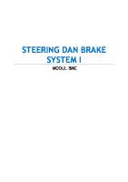
STEERING SYSTEM DESCRIPTION The purpose of the st eering syste m is to allow the
Th e ste ering system confi gurat ion depends on ve-
dri ver to cont ro l the direct ion of t he vehicle by
hi cle de sign (t he d rive train and suspension sys-
turni ng the f ront whee ls.
tems used , w hethe r it is a passenger car o r a co m-
Thi s is done by means of a steering w heel. a ste ering co lum n w hich transmits the rotation of th e steerin g w heel to the steering gears, th e st eering gears
m erc ia l vehicle, etc.l . At present, the rack-and-pinion type and the reci rcul ating-b all types are in use. The se are sh own below .
wh ich increase the rotat ional force of t he stee ring wheel in order to t ran sm it g reater torque t o the steering linkage , and th e st eering linkage w hich transmits the steering gear m ovem ent to t he f ron t w heels.
Steering wheel
Steering column
Steering col umn
Steering gear
RACK-AND-PINION TYPE STEERING
Steering linkage
RECIRCULATING-BALL TYPE STEERING
STEERING SYSTEM - Descr iption REQUIREM ENTS OF STEERING SYSTEM
The stee ring syste m plays, together w ith th e s uspe ns ion system. an im po rta nt role in ens uring easy. co mfo rta ble d riving all the way fro m the low spee d range to the high s peed ranges. The drive tra in transmits the powe r from the e ngine to the d riving wheels to m ove the ca r forwa rd; th e steeri ng svstem steers the car in the desi red direction; and th e brake system ensures pos itive, stable slowi ng and stopping .
(j) EXCELLENT M A NEUVERAB ILITY When the ca r is co rnering on a narrow . twisting road. the steering system must be a ble to t urn th e front w heels sharply ye t easily an d smoothly.
®
PROPER STEERING EFFORT
If nothing is do ne to prevent it, steering effo rt will be grea ter wh en the car is stopped and will de--
crease as the s peed of the ca r increases. Therefo re, in order to obta in easie r s teering an d better feel of the roa d, the steeri ng s hould be ma de lig hter at low s peeds and heavier at high s peeds .
@
SMOOTH RECOVERY
While the ca r is turn ing. the driver mu st ho ld the stee ring wheel firm ly. Afte r th e turn is completed, however, recovery - that is, the return of the whee ls to the straig ht-a head pos itio n - sho u ld occur smoothly as the driver rela xes the fo rce w it h which he is turn ing the s tee ring whe el.
@ MI NIM UM TRANSM ISSION OF SHOCK FROM ROAD SURFACE
loss of steering whee l control a nd trans m iss ion of kickback due to ro ad su rlace roug hn es s mu st not occur.
2
STEERING SYSTEM - Descripti on
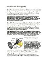
STEERING COLUMN DESCRIPTION The stee ring col um n consists of the main steering
The bottom end of the steering main shaft is con-
shaft which transmits the steering wheel rotatio n t o
nected to the steering gear, genera lly by way of a
the stee ri ng gear, and the column t ube w hic h fi xes
flexible jo int or unive rsal jo int to m inimize the trans-
the steering m ain shaft to the body . The top end of
mission of road shock from the steering gear to the
the steering main shaft is ta pered and serrated, and
steering wheel.
the steering wheel is fi tted to it by a nut.
In addition to the impact-absorbing me chanism,
The steeri ng colum n incorporates a impact absorb-
the steering ma in shaft on some veh icles may also
ing-mechanism that absorbs the thrust force that
contain a nu mber of steeri ng contro l systems: for
would otherwise be applied to the d river at the time
example, the steering lock mechanism which locks
of a collision. The steering col um n is fitted t o the
the main shaft completely; the tilt steering mecha-
body via a breakaway type column bracket so that
nism, which allows t he driver to adjust the vertica l
the steering co lum n can easily collapse in a crash .
position of the steering wheel; the te lescopic steering system, which let s the driver change the length of the steering shaft freely to obtain an optimal
I\
Steering wheel
driving pos it ion; etc .
Breakaway bracket Body
Steerin g main shaft (upper)
Tilt lever
Colum n tu be Stee ring main shaft (lower)
NON-TILT STEERIN G
OHP 1
TILT STEERING
OHP 1
3
STEERING COLUMN -
St eer ing Col umn Im pact- abso rbing Mechanism
STEERING COLUMN IMPACTABSORBING MECHANISM Whe n a ca r is invo lved in a collision, this m echa-
The steeri ng co lum n bre akaway bracket is bo lte d to
ni sm helps prevent t he ma in shaft fro m injuri ng
the instrument panel br ace v ia two capsules. Th e
t he drive r in t w o ways: by t he br eak ing at t he t ime
caps ules are inst alled ont o the col um n upper bracket
of t he co llisio n (prima ry shock); and by reduci ng
wit h four plast ic pins.
t he sec ondary sho ck im posed upon t he dr iv er's body when it hits the st eering w heel due t o inert ia .
Capsule
I
Energ y-absorbin g stee ring col um ns are classifie d int o t he fo ll owing types: • Bend ing bracket type • Ball ty pe • Sealed-in pul v erize d silicon -rubber type • M esh t ype • Bel lows ty pe
BENDING BRACKET TYPE Steering column t ube
CONSTRUCTION Breakawav bracket
A pr ess-f ormed bend ing bracket is welded t o th e co lum n t ube and f asten ed t o th e vehicle body w ith nuts. Th e capsu le po rt ion of th e breakaw ay br acket
INSTALLATION OF BREAKAWAY BRACKET
is als o f asten ed to t he body. The stee ring ma in shaft is div ide d int o u pper
OPERATION
and low er section s, w hich are co n nect ed b y
c, >c,
OHP 15
VARIABLE GEAR RATIO TYPE
C, -c.> c, 0 , " 0, " 0 ,
Varia ble gear ratio CONSTANT GEAR RATIO TYPE
OHP 15
Cons tant gear rat io 2 .5: 1
19 .5 :1
1
TUR NING AN GLE OF
SECTOR SHAFT
Stra ight a head position CONSTANT V5. VARIABLE GEAR RATIO
OHP 15
23
STEERING LIN KAGE -
Ty pes of linkage
STEERING LINKAGE A stee ring linkage is a com binatio n of the rods and arms t hat transm it th e m ovem ent of th e stee ring
Tie rod end
gea r to th e left and right f ro nt w hee ls. Th e stee ring linkage m ust accura tely transm it th e m ovem ent of t he st eering whee l t o th e front w hee ls as t hey move up and down w hile t he car is in mot ion . There are various linkage arra ngeme nts and j oi nt const ruct io ns des ig ned to do this. Th e app ro pria teness of t he design great ly affects t he stability of dri v ing .
~
Steering gear Rack end
f:8 .-.
Steering knuckle
Tie rod end OHP 16
TYPES OF LINKAGE 1. STEERING LINKAGE FOR INOEPENDENT FRONT SUSPENSION {IFSJ
2. STEERING LINKAGE FOR RIGID-AXLE FRONT SUSPENSION (RFS)
Since t he left and rig ht front w hee ls move up and
The steering linkage f or the rigid-axle f ront suspen-
down independ ently of each ot her, t he distance
sia n co nsists of t he pitm an arm, drag link, knuckle
between the knu ckl e arms v aries. This mea ns that,
arm s, ti e rod and ti e rod ends . In the rigid -axl e type
if on e ti e rod is use d to co nnect both w heels, im-
steeri ng lin kage. vertical m ove m ent of the car body
pro per toe-in w ill result w hen the w hee ls move up
do es not cause the t read (t he dista nce betwee n the
and down. Th e steering lin kage f o r the ind epen-
rig ht and [eft w hee ls) t o change, so th e rig ht and
dent fron t suspensio n t herefore uses two tie rods.
left knuck le arms can be co nnected by a sing le t ie
Th ese are con nected by a relay rod (th e rack itself
ro d.
act s as the re lay rod in the case of t he rack-an d-
Since t he stee ring gea r is f ixe d to t he f ra me. the
pi nio n type). A n adjusti ng tu be f or t oe-in adjust-
drag link, w hich co nnects it to t he knu ckle arm , is
ment is provided between th e ti e rod and t ie rod
provided with a ball j oint at each end to all ow it to
end .
move up and dow n w ith th e movements of the suspe nsio n (leaf) spri ngs.
Steering gear Steering gear
Knuckle arm
Idler arm
Tie rod end Tie rod (adjusting tube) Relay rod
Pitman arm
Tie rod OHP 16
24
Tie rod end
OHP 16
STEERING UNKAGE - linkage Com ponents
LINKAGE COMPONENTS 1. PITMAN ARM
3. TIE ROD
The pit man arm t ransmits the movement of the
The tie rod end screws into the rack end on rack-
steering gear t o the relay rod or drag link. The large
and-pinion steering , or into the adjusting tu be on
end of the arm is taper-spli ned to the secto r shaft of
reci rculating-ball steering, so that th e distan ce be-
the steering gear and f ixed by a nu t. The small end
tween joints can be adj usted.
is con nected to the relay rod or drag li nk by a ball joi nt.
Tie rod end
Rack end
Pitman arm_ _ ~~~
Tie rod end
Tie rod (adjusting tubel
Tie rod
4. TIE ROD END 2. RELAY ROD Tie rod ends are mo unted on the ends of tie rods to The relay ro d is linked to the pitma n arm and the
connect the tie rods with the knuckle arms , relay
left and right tie rods. It t ransmi ts th e motions of
rod etc. They fo rm a ball joint as shown in the
the pitm an arm to the tie rods. It is also linked t o the
il lust rati on below .
idler arm .
Ball stud
-e
Oust cover Ball seat
Idler arm
\ %:;
'"
Tie rod
Relay rod
Since the ti e rod end used in passenge r cars are usually of the lubricat ion-free ty pe, th e ball seat Tie rod
materi al used must be slow t o w ear, the sealing perform ance of the dust cove r mu st be bett er tha n usual, and non-deterior ating g rease mu st be used.
25
STEERING LINKAGE A ti e rod end incorporati ng a spring f or preload ing
and wear compensat io n as shown below is also used .
Li nkage Com ponents
6. STEERING KNUCKLE Th e ste ering knuckles support th e load applie d t o t he f ron t w heels, and also f unct ion as t he rot ati onal axes of the w hee ls. The ste ering knuck les pi v ot arou nd t he ball j oint s or king pins of t he suspen-
Ball stud
sion arm s to ste er the front wheels.
Ball joint
Dust cover
Ball sea t Spring
Ball joint
5. KNUCKLE ARMS The knuckle arms t ran sm it th e movement of th e t ie rods o r d rag link t o the f ron t whee ls v ia t he st eering The co nstructi on of t he stee ri ng knuckle and ax le
knuckles.
hub di ffers as shown in t he f ig ures be lows depending on w het he r t he car is a f ro nt-, rear -, or f ourw heel-d rive ve hi cle.
Ball joint
Axle hub Knuckle arm
Ball j oint
FR TYP E VEH ICLES
26
STEERING UNKAGE -
Linkage Com po nents
7. IDLER ARM The pivot of the idler arm is installed to the body, and the other end is co nnected to the relay rod by a sw ive l joint . Th is arm supports one end of the relay rod, and rest ricts the motion of t he relay rod to the prope r range . The idler arm bearing is of eit her the slid ing or the t orsional type. The t orsional bearing type idler arm Axle hub
uses a rubber bushi ng between the shaft and support for easy steering wheel recovery. At present, the slidi ng bear ing type id ler arm is most freq uently used due to its reduced rotational friction .
Ball joint
o
o
FF/FR TYPE VEHICLE
(Angular ball bearing ty pe)
King pin SUDING BEARING TYPE
Ax le hub
o
Steering kn uckle
o
-"c;::;,~e=;:::v~ Rubber bushing .. ,-e .- .. ~.
- ..
'-
KING PIN TYPE 4WD VEHICLES
TORSIONAL BUSHI NG TYPE
27
STEERING LINKAGE - Linkage Components
8. DRAG LINK The drag link connects t he pitm an arm to t he knuckle arm , act ing as a link w hi ch t ransm its the fo rw ard and backwa rd , and left and rig ht movements of t he pitman arm . Steering gear
Knuckl e arm
! Pitman arm Tie rod end
Pitma n arm Drag link
Screw plug
Clearance Ball seat -~ Screw plug
,
cotter om
~··~i;i~~b"~~.c
~~:~~~~J~~~ .cott., pin
Spri ng seat Spring Clearance B II Spring a seat Spring seat
Knuckle arm
9. STEERING DAMPER The steering dam per is a shock abs orbe r placed between the steering linkage and fram e t o damp the shock and v ibrat ion t ran smitted f rom the w heels to t he st eering w heel.
Steerin g damp er Relay rod
'8
TROUBLESHOOTING -
Description , Troubleshooti ng
TROUBLESHOOTING (For Manual Steerin g) DESCRIPT ION Wh en checking the steeri ng syste m, bear in m ind
Therefor e, befo re decid ing that a problem lies in
that there is a close connec tion between it and the
the steering syste m, consider and check out all
front wheels, suspensio n, ax les and frame. For th is
other possibl e causes - t his will save a lot of tim e
reason , problem s that m ay appear t o the driver as
and effort.
orig inati ng in th e steeri ng syste m, may in fact be due to other causes, such as problems in th e suspension, etc.
TROUBLESHO OTIN G EXCESSIV E STEERING WH EEL FREEPLAY
Since th ere are many joints in the steering system,
system parts and worn joints may cause the car to
a sli ght play is to be expected . However, an exces-
wa nde r or pull to o ne side, and will cause v ib ration
sive play resu lting from loosely installed steering
and abno rma l ti re we ar.
I (j)
LOOSE
CHECK STEERING COLUM N
REPA IR
I
REPA IR OR REPLACE
I
REPAIR OR REPLACE
I
I @ CHECK STEERINGWHEEL FREEPLAy-j
H
CHECK M A IN SHAFT & J OINTS
H ® CHECK LINKAGE
H
LOOSE OR WO RN LOOSE OR WOR N
CHECK ST EERING GEAR HOUSING OR GEA R BOX INSTAL LATI ON
I I
LOOSE
CHECK ST EERING GEAR BAC KLASH (fo r recircul at ing -ball type)
I I
EXCESSIVE
I @ CHECK W HEEL BEA RINGS
LOOSE
I
WORN
CHECK BALL JOINTS OR KINGPIN
I
I
TIGHTEN
I A DJ UST, REPAIR OR . I REPLACE
I I
ADJUST
I
REPLACE
I
-NOTES -
-
f
:
JJ .
O·'; ng " C @,.J Snap ring
(Ii ~_ __ __ _ _ _ _ _ _ _________
J..,/ ~ \) • Oil seal 440 (32 43) ~ , Pulley (for 2E, 4A-F Engine)
~ < ()
~
~~
Rear side plate
-, Cam ri ng Vane _ • c -nng Front side plate Shaft
I kg-cm (ft·lb, Nom) I: Specified torqu e • Non-re usable part
87
POWER STEERING -
Pow er Steering Pump Ov erha ul
DISASSEMBLY OF POWER STEERING PUMP 1.
MOUNT POWER STEERING PUMP IN VISE
~ NOTICE Do not ti ghten the vi se too t ight .
2.
- - -)
(For 2E, 4A-F & 4A-FE Engin es) REMOVE DRIVE PULLEY (a)
Usi ng th e SST to hold t he pulley, rem ove th e pu lley set nut.
SST 09616-30020 (fo r 2E &