![Emerson Door Inverter Manual [PDF]](https://pdfs.asia/img/200x200/emerson-door-inverter-manual.jpg)
9 0 2 MB
TD3200 Variable Speed Drive for Elevator Door Control User Manual Version: Revision date: BOM:
V1.4 June 15, 2005 31010971
Emerson Network Power provides customers with technical support. Users may contact the nearest Emerson local sales office or service center.
Copyright © 2004 by Emerson Network Power Co., Ltd. All rights reserved. The contents in this document are subject to change without notice.
Emerson Network Power Co., Ltd. Address: No.1 Kefa Rd., Science & Industry Park, Nanshan District 518057, Shenzhen China Homepage: www.emersonnetworkpower.com.cn Customer Service Hotline: 800-820-6510, (86) 21-23017141, (86) 755-86010800 E-mail: [email protected]
Preface Thank you for using TD3200 series drive made by Emerson Network Power Co., Ltd. TD3200 series drives are high performance vector control drives used for elevator door and various automatic door controls and other applications. Before operation, be sure to read this manual carefully to ensure correct operation and make full use of this drive's perfect functions. This manual is delivered as an accessory of the drive. Be sure to keep it properly after using. This manual is subject to changes without notification. The development and design of this product is compliant with the national standards of Elevator Manufacturing and Installation Safety Rules (GB 7588-1995). Besides, when it is used with other controller to form a system, this system can also meet the requirements of the standards if used properly. Users must install and use the product according to the national standards as well as the directions of this manual, and Emerson Network Power bears no responsibility for any human injury or material loss due to incorrect use of this product.
Contents The components, installation and wiring, daily application, fault-handling and maintenance of TD3200 series drive are described in detail in this manual.
Readers Drive installation personnel, engineering maintenance personnel and designers.
Typographic Conventions:
!
Danger
Operations that are not performed in compliant with the requirements may cause death or severe hurt.
!
Attention
Operations which are not performed in compliant with the requirements may cause medium hurt or light hurt or material damage. Note: The parts to which the operator should pay attention.
Contents Chapter 1 1.1 1.2 1.3
Safety Rules .......................................................................................... 1 Cautions in Installation............................................................................. 1 Notes for Application................................................................................ 1 Disposing of Unwanted Drive................................................................... 3
Chapter 2 2.1 2.2 2.3 2.4 2.5
Product Introduction .............................................................................. 4 Model Designation Rules ......................................................................... 4 Nameplate of Drive .................................................................................. 4 Main Models of TD3200 Series Drive ...................................................... 5 Product Specifications ............................................................................. 5 Optional Parts .......................................................................................... 8 2.5.1 Operation Keypad......................................................................... 8 2.5.2 Display Unit .................................................................................. 8 2.5.3 Braking resistors ........................................................................... 8 2.5.4 Operation Keypad Pedestal and Cables....................................... 9
Chapter 3 3.1 3.2 3.3
Installation and Wiring ......................................................................... 10 Unpacking Inspection............................................................................. 10 Installation.............................................................................................. 10 Wiring..................................................................................................... 12 3.3.1 Power Terminals of Main Circuit ................................................. 12 3.3.2 Control Terminals ....................................................................... 12 3.3.3 Wiring of Drive ............................................................................ 13 3.3.4 Wiring Requirements .................................................................. 15 3.4 Installation of Options ............................................................................ 18 3.4.1 Installation of Operation Keypad................................................. 18 3.4.2 Installation of Status Display Unit ............................................... 19 3.4.3 Installation of Braking Resistors ................................................. 20
Chapter 4 Operation............................................................................................. 21 4.1 Operation ............................................................................................... 21 4.1.1 Operation Keypad and Status Display Units............................... 21 4.1.2 Drive's Operating Status Descriptions ........................................ 23 4.1.3 Operating Mode Descriptions ..................................................... 23 4.1.4 Parameter Classification............................................................. 23 4.1.5 Parameter Setting Method.......................................................... 24
4.1.6 Display of Parameters ................................................................ 25 4.2 Basic Applications.................................................................................. 25 4.2.1 Motor Parameter Tuning............................................................. 25 4.2.2 Basic Operating Modes .............................................................. 26 Chapter 5 5.1 5.2 5.3 5.4 5.5 5.6 5.7 5.8 5.9 5.10
Parameters Table ................................................................................ 30 Basic Operation Function Parameters ................................................... 30 OD/CD Operating Parameters ............................................................... 31 Distance Control Parameters ................................................................. 33 MS Speed Parameters........................................................................... 34 Demo Parameters.................................................................................. 35 Motor's Parameters................................................................................ 35 Auxiliary Parameters.............................................................................. 36 Vector Control Parameters .................................................................... 36 Digital I/O Function Parameters ............................................................. 37 Display and Monitoring Parameters ..................................................... 39
Chapter 6 6.1 6.2 6.3 6.4 6.5 6.6 6.7 6.8 6.9 6.10
Parameter Descriptions ....................................................................... 43 Basic Operation Parameters .................................................................. 43 CD and OD Parameters......................................................................... 48 Distance Control Parameters ................................................................. 56 MS Speed .............................................................................................. 61 Demo Functions..................................................................................... 62 Motor's Parameters................................................................................ 63 Auxiliary Parameters.............................................................................. 65 Vector Control Parameters .................................................................... 66 Digital I/O ............................................................................................... 69 Display and Monitoring Functions ........................................................ 74
Chapter 7 Application Guidance........................................................................... 79 7.1 Speed control 1...................................................................................... 79 7.1.1 System Wiring Diagram .............................................................. 79 7.1.2 Testing Procedures..................................................................... 80 7.1.3 Parameters Setting ..................................................................... 80 7.2 Distance Control 1 ................................................................................. 83 7.2.1 System Wiring Diagram .............................................................. 83 7.2.2 Testing Procedures..................................................................... 84 7.2.3 Parameters Setting ..................................................................... 85 7.3 Distance control 2 .................................................................................. 88
Chapter 8 Troubleshooting................................................................................... 89 Chapter 9 9.1 9.2 9.3 9.4 9.5
Maintenance ........................................................................................ 92 Daily Maintenance ................................................................................. 93 Periodical Maintenance.......................................................................... 94 Replacing Wiring Parts .......................................................................... 95 Storage .................................................................................................. 95 Warranty ................................................................................................ 96
Chapter 1 Safety Rules
Chapter 1 1.1
!
1
Safety Rules
Cautions in Installation
Danger
Do not install the drive in an environment with explosive gas, or with the risk of explosion. Only qualified personnel are allowed to perform the wiring of the drive, or they might be at the risk of electric shock. Make sure the mains is cut off before wiring. The earth terminal of the drive must be earthed properly. Maintenance should be done after the mains has been cut off for 5 minutes, and the charger indicator is off, and the bus voltage is under 36V, or there is danger of electric shock.
Do not leave screw, washer or other metal parts inside the drive, or there is danger of fire. Please do not install or run the drive if it is damaged or lack of some parts. Avoid exposure of the drive to direct sunshine. Do not mis-connect input terminals (L, N), output terminals (U, V, W) and brake terminals (P(+), P(-), PB), or there is danger of explosion. Attention Do not connect control terminals, except TA, TB and TC, directly to ! 220V, otherwise, the drive might be damaged. Bare part of cable lugs used in main circuit wiring must be bound with insulation tape. Generally, remove the drive's cover and blow off the dust using proper tools every 1~3 months. If the over-current protection acts after start, please check if the wiring is correct and then restart .
1.2 Notes for Application Pay attention to the following issues when using TD3200 Variable Speed Drive (the drive): 1. Product Configuration TD3200 Variable Speed Drive for Elevator Door Control User Manual
2
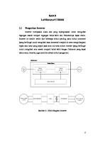
Chapter 1 Safety Rules The standard TD3200 drive has no operation keypad and display unit. You may choose them based on your needs. 2. Low Speed Running with Constant Torque Driving a common motor at low speed for a long time, the motor's life will be reduced due to the deteriorating heat dissipation effect, so a special variable speed motor for this case. 3. Insulation of Motors Before using the drive, please check the insulation ratings of the motors to avoid damage. When the environmental conditions are unfavorable to the motor, please check the insulation conditions at a regular interval to ensure the safety of the whole system. 4. Regenerating load For the load to be elevated, it may bring regenerating torque. The drive will trip due to over-current and over-voltage. If the drive needs to drive such load, you should select brake resistor. 5. Do Not Install Varistors or Capacitors at Output You must remove the capacitors or voltage sensitive devices installed at the output for improving power factor, because they will result in drive trip or other devices damaged. Besides, you'd better not install air-break switch or contactor. If you have to do so, you must ensure that when the switches act, the output current of the drive is zero. Please refer to Figure1-1. KM
U
Drive
V
M
W
Figure 1-1 Capacitors are prohibited to be connected at the drive's output 6. Derating at Base Frequency When the base frequency is set below the rated frequency, derate the drive to prevent the motor from being damaged due to overheat. TD3200 Variable Speed Drive for Elevator Door Control User Manual
Chapter 1 Safety Rules
3
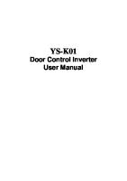
7. Altitude and derating When the altitude is higher than 1000m, the cooling effect of the drive becomes worse because of the rareness of air, so the drive must be derated. Refer to Figure 1-2. Iout 100%
90%
80% 1000
2000
3000
4000
(m)
Figure 1-2 Derating of drive's output current at different elevations 8. About the protection level The protection level of the TD3200 drive is IP20 when the display unit or the operation keypad is selected.
1.3 Disposing of Unwanted Drive When disposing the Drive, pay attention to the following factors: The capacitors may explode when they are burnt. Poisonous gas may be generated when the plastic parts like front covers are burnt. Disposing method: Please dispose the drive as industrial waste.
TD3200 Variable Speed Drive for Elevator Door Control User Manual
4
Chapter 2 Product Introduction
Chapter 2
Product Introduction
2.1 Model Designation Rules
TD3200 - 2 S xxxx D Drive series
Volt level
Code
220V
2
Code
Drive type
D
Used for elevator door
Code Motor power(kW) Input Volt
Code
Single-phase
S
0004 0002
0.4 0.2
2.2 Nameplate of Drive The Nameplate is on the bottom right of the front keypad of the drive, as shown in Figure 2-1.
MODEL :
TD3200-2S0002D
POWER :
0.2kW 1PH AC 220V~240V INPUT : 2.65A 50Hz/60Hz OUTPUT : 3PH AC 0V~240V 0~400Hz 0.5kVA 1.3A 00
S/N :
Hot line:
Drive model Motor capacity Rated input voltage,Current and frequency Rated output capacity, current and frequency range and voltage Bar code
800-820-6510 Emerson Network Power Co., Ltd.
Figure 2-1 Nameplate of drive
TD3200 Variable Speed Drive for Elevator Door Control User Manual
Chapter 2 Product Introduction
2.3
5
Main Models of TD3200 Series Drive
constant-torque Load
Drive's model
Rated input current (A)
TD3200-2S0002D
2.65
0.5
1.3
0.2
TD3200-2S0004D
5.3
1.0
2.5
0.4
2.4
Rated capacity (kVA)
Rated output current (A)
Motor power (kW)
Product Specifications
Items Input
Output
Subitems
Specifications
Voltage range
Single-phase: 180V~264V
Frequency range
50Hz±5%, 60Hz±5%
Voltage range
Three-phase: 0~220V
Frequency range
0Hz~400Hz
Over load ability
150% rated current for 1 minute, 180% rated current for 10 seconds;
Modulation mode
Optimized space voltage vector PWM modulation
Control algorithm
Sensorless vector control, vector control with speed sensor
Operation mode
Two modes: 1: The drive operates as a drive specially used for controlling the elevator door (elevator door control mode); 2: The drive operates as a general purpose drive
Frequency resolution Main control functions Auto learning
Digital setting: 0.01Hz The drive operates at the auto-learnt speed, and operates in the logic procedure of close door (CD) →open door (OD)→CD→stop. After the auto-learning operation, the door width information is saved and the auto learning process is over.
Purpose of auto tuning function of drive is to Auto tuning of motor's obtain the motor's parameters automatically and parameters these parameters will be saved automatically after the tuning process is over.
TD3200 Variable Speed Drive for Elevator Door Control User Manual
6
Chapter 2 Product Introduction Items
Main control functions
Main control functions
Subitems
Specifications
In elevator door control mode, once the drive is switched on, the door will be closed automatically, Auto operation testing after the door is closed completely, the drive will upon start stop and the door stays in completely-closed status. Acc/Dec curve
Acc/Dec according to S curve, the Acc/Dec speed is selectable
Brake
Built-in braking unit, braking resistor connected externally, utility rate of braking: 0 ~100%
Carrier frequency
2~16kHz
Multi-speed running
External terminals can be selected 8-level speed running
Under rated load condition, 1:100 for vector Speed-adjusting range control with speed sensor; 1:50 for sensorless vector control Speed accuracy
Under rated conditions, with speed sensor: 0.5% rated speed Sensorless: 1% rated speed
Start torque
150% rated torque for control mode with speed sensor at 15~300 rpm (for 4-pole motor) 150% rated torque for sensorless control mode at 30~300 rpm (for 4-pole motor)
Operation Control mode Functions Frequency setting Display
Input signal
Output signal
Terminal control mode; keypad control mode Set the frequency via keypad; operate at multi-speed level OD/CD command signal, CD/OD speed changing control signal, OD/CD location limiting signal, external reset signal; optical protection signal, MS speed control signal, OD prohibition protection signal, torque maintaining prohibition signal, low speed control signal, PG signal, door lock signal 3 relay-output: 250VAC/2A(cosφ=1), 250VAC/1A(cosφ=0.4), 30VDC/1A
TD3200 Variable Speed Drive for Elevator Door Control User Manual
Chapter 2 Product Introduction Items
Subitems
4-digit LED display (select TDP-LED02)
7
Specifications Running frequency, reference frequency, output frequency, output voltage, bus voltage, output current, output torque, DC bus voltage, status of digital input terminals, status of digital output terminals, door-operating location (pulse number)
Protection function
Over current protection, over voltage protection, low voltage protection, over heat protection, overload protection, alarm for motor's parameters tuning, alarm for parameters setting error, OD width auto-learning error, OD/CD error, output phase failure protection, alarm for CPU error, parameter r/w error, and current detection circuit fault
Optional parts
Operation keypad, status display unit, braking resistors; cables of operation keypad, operation keypad base, cables for operation keypad
Environment
Structure Mount modes
Application environment
Inside, free from direct sunlight, dust, corrosive gas, combustible gas, oil mist, steam, water drop, etc.
Elevation
Lower than 1000m (deration required for elevation above 1000m)
Working temperature
-10℃~+50℃
Humidity
Less than 90%RH, no condensation
Vibration
Lower than 5.9m/s2(0.6g)
Storage temperature
-40℃~+70℃
Protection
IP20 (under conditions of using TDP-LED02 or TDP-LED03)
Cooling
Natural air cooling without fan
Mounted on the wall or inside cabinet
TD3200 Variable Speed Drive for Elevator Door Control User Manual
8
Chapter 2 Product Introduction
2.5
Optional Parts
2.5.1
Operation Keypad The TDP-LED02 operation keypad is a standard part produced by Emerson Network Power, as illustrated in Figure 2-2.
Figure 2-2 Operation keypad
2.5.2
Figure 2-3 Status display unit
Display Unit TDP-LED03 display unit is shown in Figure 2-3. In case that several TD3200 drives are used in one site, to lower the cost, you may use one operation keypad to set the parameters for all the drives. However, each drive should be equipped with one TDP-LED03. Under this condition, you can operate the drive only through control terminals, and check basic operation status (Power-on, Run, fault) of the drive through the display unit. The dimensions of TDP-LED03 are the same with the operation keypad. The red, green and yellow LEDs on it are to indicate basic states of the drive.
2.5.3
Braking resistors The drive has a built-in brake unit. If dynamic braking is required, please select the braking resistor with reference to the table below.
Voltage
220V
Motor's Rated Power
Braking resistors
Utility of braking unit
Braking torque
Maximum continuous running time
0.2 kW
200Ω/ 80W
20(ED%)
100%
30s
0.4 kW
200Ω/ 80W
20(ED%)
100%
30s
TD3200 Variable Speed Drive for Elevator Door Control User Manual
Chapter 2 Product Introduction
Note Any special requirements for braking, please contact your supplier or Emerson Network Power.
2.5.4
Operation Keypad Pedestal and Cables The operation keypad pedestal and connecting cables are optional.
Small end
Figure 2-4 Operation keypad base
Figure 2-5 Operation keypad cable Figure2-4 shows TDF-KB01 operation keypad pedestal. There are three kinds of cables for operation keypad: TDC-CB0006A (0.6m), TDC-CB0015A (1.5m), TDC-CB0030A (3.0m). See Figure 2-5.
TD3200 Variable Speed Drive for Elevator Door Control User Manual
9
10
Chapter 3 Installation and Wiring
Chapter 3 3.1
Installation and Wiring
Unpacking Inspection Upon unpacking, please confirm the following: Any damage occurred during transportation; Check whether the rated values on the nameplate of the drive are in accordance with your order. If there is anything missed, please contact us or the your supplier.
3.2 Installation The structure of TD3200 series drive is shown in Figure 3-1 and its dimensions are shown in Figure 3-2 and Table 3-1. The drive should be installed vertically. The clearance requirements are shown in Figure 3-3 and Figure 3-4. cover keypad or status display unit control terminal cable input port of main circuit
jumpers CN9,CN10
control terminal earthing point
AC supply L,N output U,V,W DC bus and braking terminal P(+),PB,(-)
Figure 3-1 Structure of the drive
TD3200 Variable Speed Drive for Elevator Door Control User Manual
Chapter 3 Installation and Wiring
D
B
H
W A
11
Figure 3-2 Dimensions Table 3-1 Outline & Dimensions Drive's model
Motor power (kW)
Installation dimensions A(mm)
TD32002S0002D
0.2
91
TD32002S0004D
0.4
Diameter of Weight mounting (kg) B(mm) H(mm) W(mm) D(mm) hole(mm) Outline dimensions
137
145
101
130
4
1.2
Note To attain IP20 protection level, you should select display unit or the operation keypad. air expulsion by fan
above 100mm
above 50mm
above 50mm
drive ... drive Ⅰ
Ⅱ
electric cabinet
above 100mm
Figure 3-3 Clearance
Figure 3-4
Installing several drives together
TD3200 Variable Speed Drive for Elevator Door Control User Manual
12
Chapter 3 Installation and Wiring When TD3200 is used for controlling elevator 's door, it should be installed on the top of the elevator car (external surface). It's recommended to be installed vertically or placed obliquely, at 45°with the horizontal surface, with protective covering.
3.3 Wiring Note Refer to Chapter 7 Application Guidance if the drive is used for controlling the elevator door, in which the wiring methods, testing and parameter settings of several typical elevator door control applications are given.
3.3.1
Power Terminals of Main Circuit L
N
U
V
W
P(+) PB (—) Note Safety earthing cable should be connected to the screw marked with " " Functions of Power Terminals Terminal Name P(+), PB, (―)
3.3.2
Function P(+): "+" bus; PB: terminal for connecting braking unit, (—): "-" bus;
L. N
Input terminals for single-phase 220Vac
U. V. W
Output terminals for motor
PE
Terminal for earthing
Control Terminals
PA PB
PC
PAC PC1 PC2
P24 COM X1
X2
X3
X4 X5
X6
X7 COM OD CD
TD3200 Variable Speed Drive for Elevator Door Control User Manual
Chapter 3 Installation and Wiring
13
Table of Control Terminals Functions Terminal Multi-function input terminal Terminals for inputting OD and CD commands
Output terminals
3.3.3
Terminal Code
Terminal function description
X1~X7
Functions are programmable (reference GND is COM)
OD
OD command (reference GND is COM)
CD
CD command (reference GND is COM)
P24
24V power supply (reference GND is COM)
PA, PB, PC
Programmable relay output 0
PAC, PC1
Programmable relay output 1
PAC, PC2
Programmable relay output 2
Specification
24V input, X1 and X2 can meet the input requirements of pulse signal with frequency below 40kHz +24V, maximum output current is 100mA
Ratings of contacts: AC: 250V/2A; DC: 30V/1A
Wiring of Drive The basic wiring of drive's input/output terminals and external equipment are illustrated in Figure 3-5. The control terminals in the Figure below are used for setting frequency, operation control and outputting the drive's status to external monitoring devices. Its wiring method depends on your application.
TD3200 Variable Speed Drive for Elevator Door Control User Manual
14
Chapter 3 Installation and Wiring P(+) PB (—)
MCCB
L single phase power supply 50/60Hz
L
U
N
W
V N
IM
PE
multi-functional terminal 1 multi-functional terminal 2 multi-functional terminal 3 multi-functional terminal 4 multi-functional terminal 5 multi-functional terminal 6 multi-functional terminal 7
X1 X2
auxiliary power source
X3
PG power source P24
X4 X5 X6 X7
OD command input
OD
CD command input
CD
. PA main control board
PB PC
PAC
COM
PC1
PC2
defined as fault relay defaultly: * Normal,PA-PB closed Fault,PA-PC closed PC1 is defined as a relay for completely- OD: * Not completely, PAC- PC1 open Completely, PAC-PC1 closed PC2 is defined as a relay for completely- CD: * Not completely, PAC- PC2 open Completely, PAC-PC2 closed
Figure 3-5 Basic Wiring TD3200 can be fed two kinds of PG signal, and provide only 24V power supply to PG. 1. The wiring of the open-collector PG with 24V power supply is shown in Figure 3-6.
TD3200 Variable Speed Drive for Elevator Door Control User Manual
Chapter 3 Installation and Wiring using shielding cable PG of open collector output type (The part in dashed line is the VCC PG of voltage output 0V type)
TD3200
P24 ●
●
●
●
●
●
●
●
15
3.3V COM
A
VCC
X1
A VCC
0V x2
B
0V
Interface circuit is same with A
B
closer end of shielding cable is connected to PE
●
PE
Figure 3-6 Wiring of PG of open collector output type 2. Wiring with 24V power supply (push-pull output type) PG of push-pull type
TD3200
shielding Usingusing shielding cable cable
VCC
P24
VCC
●
●
0V
●
●
3.3V
COM
A
A
●
X1
VCC
●
GND B ●
X2 ●
GND
closer end of shielding cable is connected to PE
●
Interface circuit is same with A
B
PE
Figure 3-7 Wiring of PG of push-pull output type If the signal is single-phase PG signal, then it must be input via terminal X1.
3.3.4
Wiring Requirements 1. MCCB used for overcurrent protection must be installed between AC power and the drive, and it must be fixed inside the cabinet; 2. The cable diameter and MCCB capacity should be selected according to the table below:
TD3200 Variable Speed Drive for Elevator Door Control User Manual
16
Chapter 3 Installation and Wiring
Models
MCCB (A)
TD3200-2S0002D TD3200-2S0004D
Mains (mm2)
Control cables (mm2)
Input cables
Braking cables
Output cables
Earthing cables
20
1.5
1.0
1.0
2.5
0.5
20
1.5
1.0
1.0
2.5
0.5
Note 1) The "0.5 mm2" in the above table is the sectional area of a single strand of a multi-core control cables. If single-core cable is used as control cable and routed outside the cabinet, whose diameter should be no less than 1.0 mm2. 2) Before wiring, the power switch must be in "OFF" position, and drive's charging indicator must be off (the charging indicator can be seen from the hole at the top left corner if the cover is removed); 3) It is forbidden to connect the AC source cables with U, V, W, P (+), PB, (-) and PE terminals; 4) Flat cable should be used as earthing cable, and the earthing resistance should be less than 10Ω. The most favorable method is that the drive should have its own earthing pole, the less favorable method is to use a common earthing pole, but don't share one earthing cable. The earthing cable should be as short as possible, that is, the earthing point should be as close to the drive as possible. Earthing cables should be as far away from the I/O cables of the equipment that is sensitive to noise, and also should be as short as possible. drive
Other Equipment
PE
Earthing via a special pole (best)
drive
Other equipments
PE
Earthing to a common pole (OK)
drive
Other equipments
PE
Share earthing cable (forbidden)
3. It is recommended to install a line filter at the drive's power input cables The filter can reduce the interference caused by the drive on other equipment connected to the same mains. The filter's enclosure must be well earthed. The filter inside the cabinet should be placed closed to the input AC power supply and its power input cables inside the cabinet should be as short as possible. The distance between input and output cables of the filter should be as far as possible, otherwise the high frequency noise may be coupled between the cables and thus bypass the filter.
TD3200 Variable Speed Drive for Elevator Door Control User Manual
Chapter 3 Installation and Wiring
17
4. Motor cables should be as short as possible so as to reduce the leakage current to earth. 5. Selection of control cables Generally, the control cables should be shielded and the shield must be connected to the metal enclosure of the drive by cable clamps at both ends. 6. Control cables, input power cables and motor cables should be installed separately Adequate clearance should be left between the cables, especially when the cables are laid in parallel and long. If the signal cables have to cross over the power cables, keep them vertical to each other, as shown in Figure 3-8. Motor cable
>50cm
>30cm
Power cable >20cm
Signal/Control cable
Signal/Control cable
Power source or motor cable
Figure 3-8 Wiring requirements 7. Installation requirements of relay, contactor and electro-magnetic braking kit, which may generate great noises, should be installed outside of the drive cabinet and installed with surge suppressors. The suppressors are generally varistor, RC filter or diode as illustrated in Figure 3-9:
TD3200 Variable Speed Drive for Elevator Door Control User Manual
18
Chapter 3 Installation and Wiring Method 1 varistor 220VAC
Method 2
relay output
RC-filter 220VAC
Method 3 diode
+
+24VDC
-
Figure 3-9 Relay, Contactor and Brake Device
3.4 3.4.1
Installation of Options Installation of Operation Keypad 1. Installation Install the keypad on the drive: Open the plastic cover of TD3200, hold the operational keypad and keep the face of the keypad upward, align the connector of the keypad and insert the keypad directly. Install the keypad separated from the drive: use the cables you have ordered as option (see Chapter 2) to connect the keypad to the drive. Install the keypad on the keypad holder, which is fixed on the required place. Its dimensions are given as follows:
TD3200 Variable Speed Drive for Elevator Door Control User Manual
Chapter 3 Installation and Wiring
Figure 3-10
19
Dimensions of Operation Keypad
Single edge
Single edge
Figure 3-11 Installation dimensions of operation keypad 2. Notes in Installation 1) Do not connect the keypad cables alive. 2) The screws for fixing the cables is M3×6; its length must be shorter than 6mm to avoid short-circuit.
3.4.2
Installation of Status Display Unit Status display unit is installed on the drive regardless of dimensions. The installation is the same with that of the keypad. TD3200 Variable Speed Drive for Elevator Door Control User Manual
20
3.4.3
Chapter 3 Installation and Wiring
Installation of Braking Resistors Connect braking resistor between "P (+)" and "PB" with cables of proper diameters, as shown in Figure 3-12. U V W
L
M
PE
N P(+)
PB
●
●
●
●
Braking resistor
Figure 3-12
Connection between braking resistor and drive
TD3200 Variable Speed Drive for Elevator Door Control User Manual
Chapter 4 Operation
Chapter 4 4.1 4.1.1
21
Operation
Operation Operation Keypad and Status Display Units Digital display
Freq. display
PARAMETER HZ
.
Current display
A
V
Volt. Display
Program key
Pot. LED(Reserved) Freq. Pot.(Reserved)
PRG
Func. & Para. Switch Save
Shift key FUNC DATA
Running status LED RUN
Running key
Stop key Reset key
STOP RESET
Digital modification key
Figure 4-1 Operation keypad Operation Keypad Key Functions Key PRG
Name Programming
FUNC/DATA
Function /Data
Function Switches between stopping status/operating status and programming state. Select data monitor mode and data input confirmation
▲
Up
Increase
▼
Down
Decrease
Shift
In the status of RUN and STOP, press this key to select the parameters that you want to display on the screen; when setting data, press this key to select the digit you want to modify, or to switch to next function group.
XX
TD3200 Variable Speed Drive for Elevator Door Control User Manual
22
Chapter 4 Operation Key
RUN
Name
Function
Run
In the keypad control mode, press this key to start. In the keypad control mode, press this key to stop operating, or to reset and exit fault alarming status.
STOP/RESET Stop/Reset /
Frequency potentiometer
Reserved
Note In the manual tuning mode of elevator-door control, press RUN key and ▲ key at the same time to open the door, and press RUN key and key at the same time to close the door. Under general-purpose drive keypad mode, press RUN key and ▲ key at the same time to run forward, and RUN key and ▼ key at the same time to run reversely. LED Indicator's Implication Description
LED color
Symbols
Frequency unit
Green
Hz
Current unit
Green
A
Voltage unit
Green
V
Operating status
Green
RUN
Potentiometer indicator (reserved)
Green
POW RUN ERR
Fault LED(Yellow) Run LED(Green)
Power LED(Red)
Attention: The panel onle for status display.
Figure 4-2 Status display units
TD3200 Variable Speed Drive for Elevator Door Control User Manual
Chapter 4 Operation
23
Note You cannot do any operation on the status display unit.
4.1.2
Drive's Operating Status Descriptions A drive has 4 operating status. Stopping status-The drive is switched on but without any operation. Programming state-Use operation keypad to modify and set function parameters Operating status-The drive's U, V, W terminals have electricity outputs Fault alarming status-When fault occurs either from external equipment, internal or wrong operation, the drive's LED will display the fault code and lock output
4.1.3
Operating Mode Descriptions The drive has 4 operating modes: Speed control 1, Speed control 2 (multi-speed control application), Distance control 1, Distance control 2.
4.1.4
Parameter Classification There are 124 parameters totally, which are divided into 12 groups according to their functions: 1. F000-F008: for basic operation function parameters' setting 2. F010-F024: for OD curve parameters 3. F027-F042: for CD curve parameters 4. F044-F054: for distance control parameters 5. F055-F062: for MS control 6. F063-F066: only for demo of operation 7. F068-F081: for motor's parameters 8. F082~F084: auxiliary parameter 9. F088~F095: vector control parameter 10. F097~F106: digital I/O parameter
TD3200 Variable Speed Drive for Elevator Door Control User Manual
24
Chapter 4 Operation 11. F110~F121: display and monitoring 12. F124: for factory use, not open to users. Note Function parameters in group 2~4, 7 and 9~11 are set by the manufacturer as NOT DISPLAY (parameters packed). If you want to display some of the above parameters, please set F009 (group 2), F026 (group 3), F043 (group 4), F067 (group 7), F087 (group 9), F096 (group 10) or F109 (group 11) to "1". Please refer to Chapter 5 and Chapter 6 for details.
4.1.5
Parameter Setting Method Parameters can be set via the keypad only. Look at the example below: modifying F005 (low-speed operating speed) from 3Hz to 4Hz. 1. Press PRG key - to enter programming state The LED on the keypad will display current parameter code (e.g. F000) 2. Press ▲, ▼ key or SHIFT key - to search the parameter to be modified (F005) Note If there is no continuous display of parameters, please unpack the parameter group. 3. Press FUNC/DATA key - to see the settings. 4. Press XX key to shift to the bit to be modified 5. Press ▲ or ▼ key - to change the setting 6, Press FUNC/DATA key - to save and auto-display next parameter (F006) 7, Press PRG key - to exit programming state The application chart is as follows:
TD3200 Variable Speed Drive for Elevator Door Control User Manual
Chapter 4 Operation
25
Func. Code parameter settings (Example of changing the set frequecy F005 from 3.00Hz into 4.00Hz) (LED display)
F000
F005
03.00
S
FUNC DATA
PRG
①Press PRG key to enter Func. Code operation state, and display the current Func. Code
T
②PressS or T key to search the desired parameter
03.00 XX
③Press ④press XX If the FUNC/DATA key key to select the to see the setting
digit you want to modify
04.00
F006
S
FUNC DATA
T
⑤PressS or T key to modify the value
continue modifying parameters
Return to previous display
PRG
⑥After the parameter is modified, press FUNC/DATA key to save it and the next parameter will be displayed
exit after modification abandon the modification
Note When unable to modify the parameter, please refer to the following solutions: 1) The settings of some parameters are interrelated, you should set them by certain sequence. For example, F016~F017 first and then F097~F103. 2) Some parameters cannot be modified because they are fixed or actually detected, e.g. F112, F113
4.1.6
Display of Parameters 1. Define the displayed parameters during operation or at stopping state through F110~F111. 2. During operation, the defined parameters can be displayed one by one by pressing XX key on the keypad. Accordingly, certain unit indicator will turn on. 3. In stopping status, the parameter defined by F111 can be displayed one by one by pressing XX key on the keypad.
4.2 Basic Applications 4.2.1
Motor Parameter Tuning TD3200 series drives are vector control drives. It is necessary to tune motor parameters before operating. Tuning can be started via operation keypad.
TD3200 Variable Speed Drive for Elevator Door Control User Manual
26
Chapter 4 Operation Before tuning, motor must be free of load; otherwise, the results will be inaccurate. 1. Press PRG key to enter programming state. 2. Set main parameters (Other parameters can use the defaults) F069 ~ F073: Correctly input motor nameplate parameters (Please refer to Chapter 5, 6 for detailed explanation of parameters) F075=1: Tuning allowed 3. Press PRG key to return 4. Press RUN key to start motor parameter tuning and the LED displays ". In the tuning state, the motor runs on a fixed mode, so you need not " interfere. After the tuning is over, the drive stops automatically, F075 will resume to "0" and the settings of F076~F081 will be updated. If the tuning is obviously abnormal, press STOP key to stop it. Check the connections and motor ratings, then set F075=1 again. Press RUN key to start tuning. 5. A successful tuning can ensure correct control of the motor. Note If you have known the motor's parameters, you can input them into F076~F081 directly, no need to start the tuning.
4.2.2
Basic Operating Modes 1. Operating frequency settings, tuning and operating control can be done via operation keypad. 1) Press PRG key to enter programming state 2) Set main parameters (other parameters can use the defaults) F055=5.00, MS frequency 0 F001=0, speed control 1 (sensorless vector control) F002=0, in general keypad control mode 3) Press PRG key to return 4) Press RUN key and ▲ key together for FWD running. Press RUN key and ▼ key together for REV running
TD3200 Variable Speed Drive for Elevator Door Control User Manual
Chapter 4 Operation
27
5) When modify operating frequency (here means MS frequency 0) in operating status, press PRG key to enter programming state; press ▲ key or SHIFT key to shift to F055; press FUNC/DATA key to enter the settings of parameter; press XX key to move to the digit you want to modify; press ▲ or ▼ key to set the desired value; Then press FUNC/DATA key to save and auto-display F056 6) In FWD running status, press RUN key and ▼ key together, the drive will run reversely; In REV running status, press RUN key and ▲ key together, the drive will run forward. 7) Press STOP key, the drive will stop (decelerate to stop) 8) Power-off 2. Frequencies can be set and modified via the keypad and operating control through control terminals OD TD3200
CD COM
. . .
k1 k2
Figure 4-3 Wiring Connect power cables according to Figure 4-3, and switch on after confirming the connection. 1) Press PRG key to enter programming state 2) Set main parameters (other Func.Codes can use the manufacturer's settings) F055=5.00, MS frequency 0 F001=0, speed control 1 (sensorless vector control) F002=4, in general terminal control mode, the operating command is given via the control terminal. OD controls FWD running and CD controls REV running 3) Press PRG to return to stopping status 4) Switch on K1, the drive runs forward 5) During operation, the operating frequency can be modified. See part one of this section. TD3200 Variable Speed Drive for Elevator Door Control User Manual
28
Chapter 4 Operation 6) Switch off K1 and switch on K2, the drive runs REV 7) Switch off K1, K2, the drive stops (Decelerate to stop) 8) Power-off 3. Multi-speed operating can be controlled via control terminals k1 k2
. OD . CD . COM
TD3200 X3 X4 X5 COM
. . . .
k3 k4 k5
Figure 4-4 Connection of multi-speed operation Connect power cables according to Figure 4-4, and switch on after confirming the connection. 1) Press PRG key to enter programming state 2) Set main parameters (other parameters can use the defaults) F001=1, speed control 2 (sensorless vector control) F002=4, in general terminal control mode, the operating command is given via the control terminal. OD controls FWD running and CD controls REV running. F099=16, MS (multi-speed) terminal 1 F100=17, MS (multi-speed) terminal 2 F101=18, MS (multi-speed) terminal 3 3) Press PRG key to return to stopping status 4) Switch on K1 (K2), the drive runs FWD (REV) 5) Corresponding MS frequency can be selected according to the following table via the combinations of switch ON/OFF of K3, K4, K5.
TD3200 Variable Speed Drive for Elevator Door Control User Manual
Chapter 4 Operation
29
K5
K4
K3
Operating frequency
Corresponding function parameters
OFF
OFF
OFF
MS frequency 0
F055
OFF
OFF
ON
MS frequency 1
F056
OFF
ON
OFF
MS frequency 2
F057 F058
OFF
ON
ON
MS frequency 3
ON
OFF
OFF
MS frequency 4
F059
ON
OFF
ON
MS frequency 5
F060
ON
ON
OFF
MS frequency 6
F061
ON
ON
ON
MS frequency 7
F062
TD3200 Variable Speed Drive for Elevator Door Control User Manual
30
Chapter 5
Parameters Table
Chapter 5
Parameters Table
In the "Mod." column of the tables, "O" means that the parameter can be modified during operation "×" means that the parameter can not be modified during operation "*" means the actual measured or fixed parameters can not be modified "—" means that it is set by the manufacturer and can not be modified by the user Abbreviation in the table: OD: opening door CD: closing door MS: multi-speed
5.1 Para.
Basic Operation Function Parameters Name
Range
Min.unit
Default
Mod.
F000 User password
0~9999 (0000 means no password)
1
0
○
F001 Control mode
0: Speed control 1 1: Speed control 2 2: Distance control 1 3: Distance control 2
1
0
×
0: Keypad control mode of universal drive 1: Terminal control mode of the drive used for controlling elevator door 2: Manual testing mode 3: Auto-demo mode 4: Terminal control mode of universal drive
1
0
×
0.01Hz
50.00Hz
×
F002
Control commands' selection
F003 Max.output frequency
50.00Hz~400.0Hz
TD3200 Variable Speed Drive for Elevator Door Control User Manual
Chapter 5 Para.
Name
Range
31
Min.unit
Default
Mod.
1
0
×
0.01Hz
3.00Hz
×
0.1~3600s
0.1s
300.0s
×
F004
Operating direction selection
0: Conformed to the pre-set direction 1: Reversed to the pre-set direction
F005
Low-speed operation setting
0.00~50.00Hz
F006 Limit of CD or OD time
Parameters Table
F007
Delay time for OD terminal command
0~3600.0s
0.1s
0.0s
×
F008
Delay time for CD terminal command
0~3600.0s
0.1s
0.0s
×
Min.unit
Default
Mod.
1
0
○
5.2 Para.
OD/CD Operating Parameters Name
Range
Display selection for F009 F009~F025
0: Not display 1: Display
F010 OD start torque
0.0%~150%(motor rated torque)
0.1%
50.0%
×
F011 OD startup Acc time
0.1~3600s
0.1s
1.0s
○
Low speed setting in F012 OD startup process
0.00~50.00Hz
0.01Hz
10.0Hz
×
0.1s
1.0s
○
0.01Hz
35.00Hz
○
F013
Low speed maintaining time at OD start
0.1~3600s
F014
OD reference frequency setting
0~Max. frequency(Hz)
F015 OD Acc time
0.1~3600s
0.1s
2.0s
○
Initial time of "S" shape F016 curve in OD Acc process
10.0%~50.0%( Acc/Dec time) F016+F017 ≤90%
0.1%
20.0%
×
Rising time of "S" F017 shape curve in OD Acc process
10.0%~80.0%( Acc/Dec time) F016+F017 ≤90%
0.1%
60.0%
×
F018 OD Dec time
0.1~3600s
0.1s
2.0s
○
TD3200 Variable Speed Drive for Elevator Door Control User Manual
32 Para.
Chapter 5
Parameters Table
Name
Range
Min.unit
Default
Mod.
10.0%~50.0%(Acc/ Dec time) F019+F020 ≤90%
0.1%
20.0%
×
10.0%~80.0%(Acc/ Dec Dropping time of "S" F020 shape curve in OD Dec time) F019+F020 ≤90% process
0.1%
60.0%
×
0.01Hz
3.00Hz
×
Initial time of "S" shape F019 curve in OD Dec process
F021
Low speed setting in OD ending phase
0.00~50.00Hz
F022
Holding torque in complete OD status
0.0%~150%(Motor rated torque)
0.1%
50.0%
×
F023
Threshold setting for OD torque changing
0.0%~150%(Motor rated torque)
0.1%
50.0%
×
0.1~100s
0.1s
0.5s
○
F024 Abnormal Dec time F025 Reserved Display selection for F026 F026~F042
0: No display of this function module 1: Display of this function module
1
0
○
F027 Start torque for CD
0.0%~150%(Motor rated torque)
0.1%
50.0%
×
F028 CD startup Acc time
0.1~3600s
0.1s
1.0s
○
0.01Hz
8.00Hz
×
0.1s
1.0s
○
0.01Hz
30.00Hz
○
0.1~3600s
0.1s
2.0s
○
F029
Low speed setting in CD startup process
0.00~50.00Hz
F030
Low speed maintaining time at CD startup
0.1~3600s
F031
CD reference frequency 0.00~Max. setting frequency(Hz)
F032 CD Acc time F033
Initial time of "S" curve in CD Acc process
10.0%~50.0%(Acc/Dec time) F033 +F034 ≤90%
0.1%
20.0%
×
F034
10.0%~80.0%(Acc/Dec Rising time of "S" curve time) in CD Acc process F033+F034 ≤90%
0.1%
60.0%
×
0.1s
2.0s
○
F035 CD Dec time
0.1~3600s
TD3200 Variable Speed Drive for Elevator Door Control User Manual
Chapter 5 Para.
33
Range
Min.unit
Default
Mod.
F036
Initial time of "S" curve in CD Dec process
10.0%~50.0%(Acc/Dec time) F036+F037 ≤90%
0.1%
20.0%
×
F037
10.0%~80.0%(Acc/Dec Falling time of "S" curve time) in CD Dec process F036+F037 ≤90%
0.1%
60.0%
×
F038
Low speed setting in CD ending phase
0.00~50.00Hz
0.01Hz
2.00Hz
×
F039
Holding torque in complete CD status
0.0%~150%(Motor rated torque)
0.1%
50.0%
×
Hindering torque setting 0.0%~150%(Motor F040 for CD high speed rated torque) phase
0.1%
100.0%
×
0.0%~150%(Motor rated torque)
0.1%
50.0%
×
0.0%~150%(Motor rated torque)
0.1%
100.0%
×
Min.unit
Default
Mod.
F041
Name
Parameters Table
Threshold setting for CD torque changing
Hindering torque F042 setting for CD low speed end phase
5.3 Para.
Distance Control Parameters Name
Setting Range
F043
Display selection for F043~F066
0: Not display 1: Display
1
0
○
F044
Number of pulse per revolution
1~9999
1
128
×
F045
Number of phases of PG
0: double phase 1: single phase
1
0
×
0: FWD 1: REV
1
0
×
0.01Hz
5.00Hz
×
F046 Direction of PG F047
Speed in door-width auto-learning
0~50.00Hz
TD3200 Variable Speed Drive for Elevator Door Control User Manual
34 Para.
Chapter 5
Parameters Table
Name
Setting Range
Min.unit
Default
Mod.
1
0
×
OD speed changing 60.0%~90.0%(door-widt F049 position under Distance h) control
0.1%
70.0%
×
CD speed changing 60.0%~90.0%(door-widt F050 position under Distance h) control
0.1%
70.0%
×
Pulse setting for F051 completely OD under Distance control
80.0%~99.0%(door-widt h)
0.1%
95.0%
×
Pulse setting for F052 completely CD under Distance control
80.0%~99.0%(door-widt h)
0.1%
95.0%
×
0, 1. From 0 → 1 to
F048
start door-width auto-learning, then auto turn to 0 after finishing. Auto-learning is effective in motor manual tuning mode
Door-width auto-learning setting
F053
Lower four digits of door-width pulse
0~9999
1
0
×
F054
Higher four digits of door-width pulse
0~9999(*10000)
1
0
×
5.4
MS Speed Parameters
Para.
Name
Range
Min.unit
Default
Mod.
F055
MS frequency 0
0.00Hz~Max. frequency(Hz)
0.01Hz
50.00
○
F056
MS frequency 1
0.00Hz~Max. frequency(Hz)
0.01Hz
5.00
○
F057
MS frequency 2
0.00Hz~Max. frequency(Hz)
0.01Hz
10.00
○
F058
MS frequency 3
0.00Hz~Max. frequency(Hz)
0.01Hz
15.00
○
F059
MS frequency 4
0.00Hz~Max. frequency(Hz)
0.01Hz
20.00
○
F060
MS frequency 5
0.00Hz~Max. frequency(Hz)
0.01Hz
30.00
○
F061
MS frequency 6
0.00Hz~Max. frequency(Hz)
0.01Hz
40.00
○
F062
MS frequency 7
0.00Hz~Max. frequency(Hz)
0.01Hz
50.00
○
TD3200 Variable Speed Drive for Elevator Door Control User Manual
Chapter 5
5.5
Parameters Table
35
Demo Parameters
Para.
Range
Min.unit
Default
Mod.
Holding time for completely OD in F063 demo mode
1~3600s
0.1s
2.0s
○
Holding time for completely CD in demo mode
1~3600s
0.1s
2.0s
○
F065 CD/OD times in demo mode
0~9999
1
0
×
F066 Preset CD/OD times in demo mode
0~9999
1
0
×
F064
5.6 Para.
Name
Motor's Parameters Min.unit
Default
Mod.
F067
Display selection F067 ~F086
Name
0: Not display 1: Display
Range
1
0
○
F068
Motor type selection
0: Asynchronous motor (1, 2: Reserved)
1
0
×
F069
Motor rated power
0~750W
1W
370W
×
F070
Motor rated voltage
0~380V
1V
220V
×
F071
Motor rated current
0.10A~9.90A
0.01A
1.94
×
F072
Motor rated frequency
1.00Hz~400.0Hz
0.01Hz
50.00Hz
×
F073
Motor rated speed
1~9999rpm
1rpm
1400rpm
×
F074
Reserved
1
0
×
0.01Ω
7.73 Ω
×
1mH
357mH
×
0.01Ω
5.23 Ω
×
F075
Auto-tuning for getting motor's parameters
0: tuning disabled 1: tuning enabled F075 will turn to "0" automatically after tuning finished. effective in keypad control mode
F076
Stator resistance
00.00~99.99Ω
F077
Stator inductance
0~9999mH
F078
Rotator resistance
00.00~99.99Ω
TD3200 Variable Speed Drive for Elevator Door Control User Manual
36 Para.
Chapter 5
Parameters Table
Name
Range
Min.unit
Default
Mod.
F079
Rotator inductance
0~9999mH
1mH
357mH
×
F080
Mutual inductance
0~9999mH
1mH
325mH
×
F081
Magnetising current without load
0.00~99.99A
0.01A
1.08A
×
5.7 Para. F082
Auxiliary Parameters Name
Range
Min.unit
Default
Mod.
Carrier frequency
2.0kHz~16.0kHz
0.1kHz
8.0kHz
×
Auto reset times upon fault
0~100, 0 means without auto reset function (reset interval time :2s)
1
0
×
F084
Utility rate of braking
0: Without dynamic braking 1: 2.0% 2: 5.0% 3: 10.0% 4: 20.0% 5: 50.0% 6: 80.0% 7: 100.0%
1
7
○
F085
Reserved
F086
Reserved
Min.unit
Default
Mod.
1
0
○
0.001
1.000
×
0.001s
1.000s
×
0.001
1.200
×
F083
5.8 Para. F087
Vector Control Parameters Name Display selection F087 ~F095
Range 0: Not display 1: Display
F088 ASR proportional gain 1 0.000~6.000 F089 ASR integral time 1
0 (no action), 0.032~32.00s
F090 ASR proportional gain 2 0.000~6.000
TD3200 Variable Speed Drive for Elevator Door Control User Manual
Chapter 5 Para.
Name
Range
Parameters Table
37
Min.unit
Default
Mod.
0(no action), 0.032~32.00s
0.001s
0.400s
×
0.00~400.0Hz
0.01Hz
5.00Hz
×
F093 Slip compensation gain
0 (reserved function), 50.0%~250.0%(for accounting the slip value)
0.1%
100.0%
×
F094 Motoring torque limiting
0.0~200.0%(rated current)
0.1%
100.0%
×
F095 Braking torque limiting
0.0~200.0%( rated current)
0.1%
100.0%
×
F091 ASR integral time 2 F092
5.9 Para. F096
ASR switching frequency
Digital I/O Function Parameters Name
Range
Display selection 0: Not display F096~ F108 1: Display
F097 Function of X1
F098 Function of X2
F099 Function of X3
F100 Function of X4
0: No function (can be selected again) 1: External reset(RESET)input 2: Normally open input for optic signal 3: Normally closed input for optic signal 4: Normally open input for touching board 5: Normally closed input for touching board 6: OD position control signal normally open input 7: OD position control signal normally closed input 8: CD position control signal normally open input 9: CD position control signal normally closed input 10: PG A-phase signal input(X1,X2) 11: PG B-phase signal input(X1,X2) 12: OD speed-shift contact normally open i t
Min. Default Mod. unit 1
0
○
1
0
×
TD3200 Variable Speed Drive for Elevator Door Control User Manual
38
Para.
Chapter 5
Parameters Table
Name
F101 Function of X5
F102 Function of X6
F103 Function of X7
Function of programmable F104 relay output PA/PB/PC Function of programmable F105 relay output PAC/PC1 Function of programmable F106 relay output PAC/PC2 Definition of F107 relay PC1 and PC2 contacts F108
OD priority function setting
Range
Min. Default Mod. unit
1 input 13: OD speed-shift contact normally closed input 14: CD speed-shift contact normally open input 15: CD speed-shift contact normally closed input 16: MS terminal 1 17: MS terminal 2 18: MS speed terminal 3 19: OD prohibiting terminal input 20: Torque maitaining prohibiting terminal input 21: Low speed OD/CD enabling input 22: Locking signal permanent ON input 23: Locking signal permenant OFF input 24: Operation enabling signal input (valid only for X7)
0
×
4
×
0
×
1
×
0: Output signal 0 for completely OD 1: Output signal 0 for completely CD 2: Output signal 1 for completely OD 3: Output signal 1 for completely CD 4: Fault relay output 1(POFF state excluded) 5: Fault relay output 2(POFF state included) 6: Output signal 2 for completely OD 17: Output signal 2 for completely CD 8: Locking signal output 9: Door re-opening signal output
1
0~3
0
1
×
0~1
1
0
×
TD3200 Variable Speed Drive for Elevator Door Control User Manual
Chapter 5
5.10 Para. F109
Parameters Table
39
Display and Monitoring Parameters Name Display selection F109 ~F122
Range 0: Not display 1: Display
Min. unit
Default
Mod.
1
0
○
1
31(00011111B )
○
Setting of the bit: 0: not display 1: display BIT0: operating frequency (Hz) BIT1: reference frequency (Hz) BIT2: output voltage (V-RMS) BIT3: output current (A-RMS) BIT4: output torque (%) Parameters displayed BIT5: DC bus voltage (V-AVE) F110 by LED during BIT6: status of idgital input operation terminal(no unit) BIT7: status of idgital output terminal(no unit) BIT8: low bit of pulse number of door location(0~9999) BIT9: high bit of pulse number of door location(0~9999) Note: all the values F110 chooses to monitor can be displayed by pressing XX key during operating,
TD3200 Variable Speed Drive for Elevator Door Control User Manual
40
Chapter 5
Parameters Table Min. unit
Default
Mod.
0: Preset OD frequency (Hz) 1: Preset CD frequency (Hz) 2: Status of digital input terminal(no unit) Parameters displayed 3: Status of digital output F111 by LED in stopping terminal(no unit) status 4: DC bus voltage (V-AVE) 5: MS frequency 0(Hz) 6: Low bit of pulse of door location(0~9999) 7: High bit of pulse of door location(0~9999)
1
0
○
0: No abnormal record(clear abnormal record) 1: Acc over current (E001) 2: Dec over current (E002) 3: Constant speed over current (E003) 4: Acc over voltage (E004) 5: Dec over voltage (E005) 6: Constant speed over voltage (E006) 7~8: Reserved 9: Output side phase loss(E009) 10: Reserved 11: Heatsink overheat(E011) 12,14,15: Reserved 13: Drive overload
1
0
×
Para.
Name
F112 Type of 1st fault
F113 Type of 2nd fault
Range
TD3200 Variable Speed Drive for Elevator Door Control User Manual
Chapter 5
Para.
Name
F114 Type of 3rd fault
Range 16: EEPROM R/W fault(E016) 17~18: Reserved 19: Current detection circuit fault(E019) 20: CPU fault 21~23: Reserved 24: Tuning fault(E024) 25~27: Reserved 28: Parameters setting fault(E028) 29: Door-width auto-learning fault(E029) 30: OD/CD operation fault(E030)
Parameters Table
41
Min. unit
Default
Mod.
1
0
×
1V
0V
×
F115
DC bus voltage (V) at 0~999V the latest fault
F116
Output current (A) at 0.00~99.99A the latest fault
0.01A
0.00A
×
F117
Output frequency at the latest fault
0.01Hz
0.00Hz
×
Status of input 0~1023 (0: OFF; 1: ON) F118 terminal at the latest CD/OD/X7/X6/X5/X4/X3/X fault 2/X1
1
0
×
Status of output 0~15 (0: OFF; 1: ON) F119 terminal at the latest PR0/PR1/PR2 fault
1
0
×
F120 Total operation time
0~65535 hour
1
0
×
Temperature codes F121 used in factory testing
0~9999
1
0
×
F122 Sofware version No.
32.XX
-
-
-
0.00Hz~400.0Hz
TD3200 Variable Speed Drive for Elevator Door Control User Manual
42
Para.
Chapter 5
Parameters Table
Name
Range
Min. unit
Default
Mod.
Parameter F123 initialization
0: no operation 1: Clear memory information 2: Resume factory setting
1
0
%
F124 Factory password
****
-
-
-
TD3200 Variable Speed Drive for Elevator Door Control User Manual
Chapter 6 Parameter Descriptions
Chapter 6
43
Parameter Descriptions
Note Reference frequency: Target frequency at which the drive operates stably. Operating frequency: The drive's actual output frequency during operation. The parameters in "【】" are defaults. Only qualified personnel is allowed to test this product, otherwise, accidents might occur;
! Danger
Make sure that the mechanical system and electrical connections of elevator door are correct, accidents might occur; All the parameters must be set properly according to relevant industrial standards, otherwise, accidents might occur; Don't walk to the area where the door is under testing, otherwise, personal injuries might occur.
6.1
Basic Operation Parameters
F000 User Password
Range: 0~9999 【0】
Set up any non- zero number as user's password to enable the password protection function. 0000: no password, the access of parameter is not protected. Attention Once user's password is set, you can only read the parameters but not set or modify them if you don't input the correct password. F001 Control mode
Range: 0~3 【0】
0: Speed control 1 The drive operates in sensorless vector control mode. When the drive is used to control an elevator door, the speed can be changed by connecting different speed contacts, and the complete CD or OD can is controlled by a limit switch. 1: Speed control 2 TD3200 Variable Speed Drive for Elevator Door Control User Manual
44
Chapter 6 Parameter Descriptions The drive operates in sensorless vector control mode. The reference frequency can be determined by the logic combinations of multi-speed terminals. When the drive controls an elevator door, the complete CD or OD is controlled by a limit switch. 2: Distance control 1 The drive operates in vector control mode with speed sensor. The PG parameters must be set correctly, otherwise the accuracy of control and door width cannot be ensured. When the drive controls an elevator door, the door width should be obtained by auto-learning, and the result will be saved. Besides, the distance control parameters (F049~F052) should be set correctly. During operation, the pulse count value will be compared with the preset value to achieve varied speed and complete CD or OD. In this mode, PG must be connected to the motor's shaft. 3: Distance control 2 The drive operates in vector control mode without speed sensor. When the drive operates as a drive controls elevator door, the PG parameters must be set correctly, otherwise the accuracy of door width cannot be ensured. The door width should be obtained via auto-learning, and the door width information should be saved after auto-learning. Besides, the distance control parameters (F049~F052) should be set correctly. During operation, the pulse count will be compared with the preset value varied speed and complete CD or OD. In this mode, PG may not be connected to the motor's shaft.
F002 Control commands selection
Range: 0~4 【0】
0: Keypad control mode of general-purpose drive The starting and stopping of the drive is controlled through the keypad of the drive (if the keypad is selected). The drive runs forward if RUN and ▲ are pressed at the same time, and reversely if RUN and ▼ are pressed at the same time, and stops if STOP is pressed. In this control mode, the drive operates as a general-purpose drive and will not follow the command for elevator door control. Besides, the motor parameters tuning is only active in keypad control mode. 1: Terminal control mode for controlling elevator door
TD3200 Variable Speed Drive for Elevator Door Control User Manual
Chapter 6 Parameter Descriptions
45
The drive sends OD and CD commands via control system to realize door opening or closing. The operating logic is shown in Figure 6-1. K1
K2
operating command
0
0
stop
K1 K2
1
0
0
1
1
1
OD
. . .
OD CD
TD3200 drive
COM
CD OD
Figure 6-1 Terminal control logic 2: Manual testing mode In this mode, you can test the door operation and set the CD and OD control signal as well as all the relevant parameters of CD and OD operation curves. Press RUN and ▲ together to open door, press RUN and ▼ together to close door, and press STOP to stop the drive. Attention Door width auto-learning is only valid in manual testing mode. Pressing RUN can start the auto-learning. 3: Auto-demo mode Auto-demo mode is used for demonstrating the operation or commissioning of the drive in the factory, no need to be controlled by the control system. The auto-demo mode can be set after the drive's operation curve is set in manual testing mode. Press RUN to start the demonstration of OD and CD repetitively, and the interval between CD and OD can be set by F063 and F064. Pressing STOP to stop the demo. 4: Terminal control mode of general-purpose drive The starting and stopping of the motor can be controlled via OD and CD terminals. The operation logic is shown in Figure 6-2. In this control mode, the drive will not perform the functions of elevator door control.
TD3200 Variable Speed Drive for Elevator Door Control User Manual
46
Chapter 6 Parameter Descriptions
K1
K2
operation command
0
0
stop
K1 K2
1
0
run forward
0
1
run reverse
1
1
. . .
OD CD
TD3200 drive
COM
run forward
Figure 6-2 Terminal control mode of general-purpose drive F003 Max. output frequency
Range: 50.00~400.00Hz 【50.00】
Max. output frequency is the highest frequency output from the drive, see fmax in Figure 6-3; Rated frequency (also called base frequency) is the minimum output frequency at the rated voltage, see fb in Figure 6-3. If the base frequency is set too low, motor overheat may occur or even be damaged when operating at it for a long time; Generally, rated voltage is set at the motor's rated voltage.
Vrated
Output volt
Output Freq.
fL
fb fH fmax
Figure 6-3 Illustration of characteristic parameters F004 Running direction selection
Range: 0、1 【0】
Motor's running direction can be changed by setting F004. The motor's running direction is determined after the motor is wired correctly. You can change the setting of F004 to change the direction without rewiring the motor. 0: Same with preset direction 1: Reverse to preset direction TD3200 Variable Speed Drive for Elevator Door Control User Manual
Chapter 6 Parameter Descriptions F005 Low-speed operation setting
47
Range: 0.00~50.00Hz 【3.00】
F005 is to set the speed of low speed operation including the auto-testing at start-up, and the operation when the low speed running command is effective. Note Auto-testing at start-up: If the drive is set in elevator-door control mode, when it is powered on, it will conduct low-speed CD at first. If it is interrupted during closing the door, it will open it again, and close it after the door is opened completely. After that, the drive stops and the auto-testing is over. F006 CD or OD time limit
Range: 0.1~3600s 【300.0】
F006 is used to set the maximum time of CD and OD operation. You should set it properly according to the actual conditions. The settings must be bigger or equal to the sum of all the settings of CD or OD (parameter group of CD and OD curve), otherwise error may occur (E028). Setting F006 correctly can protect the system against abnormal operation of elevator door. The normal operation time will not exceed F006, but when the CD or OD position limit is invalid, which may cause the door cannot be opened or closed to the position, the operation time may exceed F006, CD or OD error (E030) will be activated. Note 1) OD time: The duration from the drive receiving OD command until the door is opened completely. 2) CD time: The duration from the drive receiving CD command until the door is closed completely. 3) When the drive operates as a general-purpose drive, this parameter is invalid. F007 Delay time for OD terminal command
Range: 0~3600.0s 【0.0s】
F007 is to set the time interval from the OD command becoming invalid to the end of holding time of complete OD state. If the holding time is equal or greater than F007, the drive will stop. If the door is not opened to the position completely and OD command is cancelled at that time, the drive will stop immediately and the delay function is invalid.
TD3200 Variable Speed Drive for Elevator Door Control User Manual
48
Chapter 6 Parameter Descriptions If F007 is set to 3600s, the OD delay, once triggered, will be maintained endlessly. If F007 is set to 3599 or anything below, the OD delay will be maintained as per the actual setting of F007.
F008 Delay time for CD terminal command
Range: 0~3600.0s 【0.0s】
F008 is to set the time interval from the CD command becoming invalid to the end of holding time of complete CD state. If the holding time is equal or greater than F008, the drive will stop. If the door is not closed to the position completely and CD command is cancelled at that time, the drive will stop immediately and the delay function is invalid. If F008 is set to 3600s, the CD delay, once triggered, will be maintained endlessly. If F008 is set to 3599 or anything below, the CD delay will be maintained as per the actual setting of F008.
6.2
CD and OD Parameters Let's take speed control 1 for example to explain the process of OD and CD. The locations of various control contacts (operating switches) are shown in Figure 6-4. OD position limiting signal OD varied-speed contacts
Location of complete OD
CD CD varied-speed OD position contacts limiting signal
Location of complete CD OD
Figure 6-4 Varied-speed contacts for speed control 1 Set the function parameters from F010 to F040. Define the varied-speed contacts and position limiting signal accurately. Operating curve is illustrated in Figure 6-5 and Figure 6-6.
TD3200 Variable Speed Drive for Elevator Door Control User Manual
Chapter 6 Parameter Descriptions
49
Frequency F014
F013 F011
F023 F015
Time
OD Speed changing signal for OD Location limiting signal for OD
F022
F018
F012 F021
OFF
ON OFF OFF
ON ON
Figure 6-5 Illustrations of OD operating curve for speed control 1 Notes for OD process of speed control 1: ① When the OD command is active, the elevator door starts with start torque for OD (F010), and accelerates to Low speed in OD startup process (F012) according to OD startup Acc time (F011), and then operates at constant speed in low-speed section. ② Start timing when the OD starts, when the time is counted to low-speed holding time of OD startup (F013), the elevator door starts to operate at OD reference frequency (F014), and accelerates according to OD Acc time (F015), and then operates at high speed after the acceleration. ③When the OD speed changing signal is active, the elevator door decelerates according to OD Dec time (F018), and then operates at low speed with low speed setting in OD ending phase. ④When OD location limiting signal is active, the elevator door continues to run at OD low speed, and the drive judge the output torque. If the torque is bigger or equal to the threshold of OD torque changing (F023), the drive will keep the OD torque of F022, thus the whole OD process is over. ⑤When OD command is cancelled, the drive will not maintain the OD torque any more.
TD3200 Variable Speed Drive for Elevator Door Control User Manual
50
Chapter 6 Parameter Descriptions Frequency F031
F035
F030 F028
F041 F039
F032
F029 F038
time
CD CD speed changing signal CD location limiting signal
OFF
ON OFF
ON
OFF
ON
Figure 6-6 Illustrations of CD operating curve of speed control 1 Notes for CD process of speed control 1: ① When the CD command is active, the elevator door starts with start torque for CD (F027), and accelerates to Low speed in CD startup process (F029) according to CD startup Acc time (F028), and then operates at constant speed in low-speed section. ② Start timing when the CD starts, when the time is counted to low-speed holding time at CD startup (F030), the elevator door starts to operate at CD reference frequency setting (F031), and accelerates according to CD Acc time (F032), and then run at high speed after the acceleration. ③When the CD speed changing signal is active, the elevator door decelerates according to CD Dec time (F035), and then runs at low speed with low speed setting in CD ending phase (F038) as the target speed. ④When CD location limiting signal is active, the elevator door continues to run at CD low speed, and the drive judge the output torque. If the torque is bigger or equal to the threshold for CD torque changing (F041), the door will maintain its torque at F039, thus the whole CD process is over. ⑤When CD command is disabled, the drive exits the CD torque maintaining status. See distance control parameters for distance control operating curve. F009 Display selection for F009~F025
Range: 0、1 【0】
F009 decides whether to display the parameter group (F010~F025). 0: Not display
TD3200 Variable Speed Drive for Elevator Door Control User Manual
Chapter 6 Parameter Descriptions
51
1: Display Note In parameters displaying status, press XX to scroll through the parameters that are allowed to display. The parameter of "Display selection for xxx~xxx" will be displayed first. F010 OD start torque
Range: 0.0%~150.0%【50.0】
F010 is used to set the start torque when the drive starts to open the door to ensure smooth operation. The value of the torque is the product of F010 and the rated torque. F011 OD startup Acc time
Range: 0.1s~3600s 【1.0】
F011 is to set the time taken for accelerating from zero speed to low speed in OD startup process. Note 1. Acc time is the time taken for the drive to accelerate from 0Hz (zero speed) to the maximum frequency (maximum speed). 2. Dec time is the time taken for the drive to decelerate from maximum frequency (maximum speed) to 0Hz (zero speed). F012 Low speed in OD startup process
Range: 0~50.00Hz 【10.00】
F012 is used to set the low operating frequency (speed) in OD process. F013 Low-speed maintaining time at OD startup
Range: 0.1s~3600s 【1.0】
F013 is used to set the low-speed operating time including the Acc time and constant speed operating time in OD startup process. F014 OD reference frequency setting
Range: 0~Maximum frequency【35.00】
F014 is used to set the high operating frequency (speed) in OD process. F015 OD Acc time
Range: 0.1s~3600s 【2.0】
F015 is used to set the time taken for the elevator door to accelerate from the OD startup low speed to the OD frequency in OD process. F016 Initial time of "S" -shape curve in OD Acc process
Range: 10.0%~50.0%【20.0%】
TD3200 Variable Speed Drive for Elevator Door Control User Manual
52
Chapter 6 Parameter Descriptions F016 defines the ratio of the initial time("①" of T1 in Figure 6-7) of "s"-shape curve to the whole Acc time, as shown in Figure 6-7, which is "①" of T1. TD3200 drive accelerates and decelerates according to the "S"-shape curve shown in Figure 6-7. Descriptions of "S"-shape curve: In drive's Acc/Dec process, the output frequency decreases or increases with the Acc/Dec time according to the "S"-shape curve, as shown in Figure 6-7. output frequency Fmax
1
3
2
2 1
3 T1
running time
T2
Figure 6-7 S curve Acc and Dec F017 Rising time of "S" -shape curve in OD Acc process
Range: 10.0%~80.0%【60.0%】
F017 defines the ratio of the rising time("②" of T1 in Figure 6-7) of "s"-shape curve to the whole Acc time, as shown in Figure 6-7, which is "②" of T1. F018 OD Dec time
Range: 0.1s~3600s 【2.0】
F018 defines time taken for the elevator door to decelerate from the OD frequency (high speed) to the low speed in OD ending status in OD process. F019 Initial time of "S"-shape curve in OD Dec process
Range: 10.0%~50.0%【20.0%】
F019 defines the ratio of the initial time("①" of T2 in Figure 6-7) of "s"-shape curve to the whole Dec time, as shown in Figure 6-7, which is "①" of T2. F020 Dropping time of "S" -shape curve in OD Dec process
Range: 10.0%~80.0%【60.0%】
F020 defines the ratio of the dropping time("②" of T2 in Figure 6-7) of "s"-shape curve to the whole Dec time, as shown in Figure 6-7, which is "②" of T2. F021 low speed setting in OD ending phase
Range: 0~50.00Hz 【3.00】
TD3200 Variable Speed Drive for Elevator Door Control User Manual
Chapter 6 Parameter Descriptions
53
F021 defines the motor's low operating frequency (speed) after the OD speed changing signal is active in OD process. F022 Holding torque in complete OD status
Range: 0.0%~150.0%【50.0%】
When the motor is in OD operating process, the OD location limiting function is enabled. When the torque of catching spinning motor is bigger or equal to the setting of F023, and in the mean time the torque-holding-prohibition function is disabled, the elevator door maintains at complete OD status with the holding torque of the product of F022 and motor's rated torque. F023 Threshold for OD torque changing
Range: 0.0%~150.0%【50.0%】
In OD process, if the OD location limiting signal is active or the pulse count for distance control reaches the product of F051 and the door width, the elevator door continues to run at low speed in the ending phase of OD. When the door reaches the limited location, the motor is caught. When the motor catching torque is bigger or equal to the product of F023 and motor's rated torque, the door is in complete OD status and maintaining the current torque until the door opens again or stops. F024 Abnormal Dec time
Range: 0.0~100s 【0.5s】
If re-OD command is active, F024 defines the time taken for the elevator door decelerates from CD operating frequency to zero. Under the condition of ensuring no over-current in Dec process, F024 should be set as small as possible so as to ensure the fast return of the door. F025 Reserved F025 is reserved and not open to users. If operation keypad is used, after entering the reserved unit, the keypad LEDs will display " F026 Display selection for F026~F042
".
Range: 0, 1 【0】
F026 decides whether F027~F042 can be displayed or not. 0: Not display 1: Display F027 Start torque for CD
Range: 0.0%~150.0%【50.0%】
TD3200 Variable Speed Drive for Elevator Door Control User Manual
54
Chapter 6 Parameter Descriptions F027 is used to set the start torque when the elevator door starts to close the door so as to ensure good CD effects. The value of the torque is the product by multiplying the setting of F027 by the rated torque.
F028 CD startup Acc time
Range: 0.1s~3600s 【1.0】
F028 is used to set the time taken for the elevator door to accelerate from zero speed to low speed in CD startup process. F029 Low speed in CD startup process
Range: 0~50.00Hz 【8.00】
F029 is used to set the target frequency (speed) of low operation speed in CD process. F030 Low-speed maintaining time at CD startup
Range: 0.1s~3600s 【1.0】
F030 is used to set the low-speed operating time including the Acc time and constant speed operating time in CD startup process. F031 CD reference frequency
Range: 0~Maximum frequency【30.00】
F031 is used to set the high operating frequency (speed) in CD process. F032 CD Acc time
Range: 0.1s~3600s 【2.0】
F032 is used to set the time taken for the drive to accelerate from the CD startup low speed to the CD reference frequency in CD process. F033 Initial time of S curve in CD Acc process
Range: 10.0%~50.0%【20.0%】
F033 defines the ratio of the initial time of S curve (① of T1 in Figure 6-7 ) to the whole Acc time T1. See Figure 6-7. F034 Rising time of S curve in CD Acc process
Range: 10.0%~80.0%【60.0%】
F034 defines the ratio of the rising time(② of T1 in Figure 6-7) of S curve to the whole Acc time T1. See Figure 6-7. F035 CD Dec time
Range: 0.1s~3600s 【2.0】
F035 defines time taken for the drive to decelerate from the CD reference frequency (high speed) to the low speed in CD ending status. F036 Initial time of S curve in CD Dec process
Range: 10.0%~50.0%【20.0%】
F036 defines the ratio of the initial time(① of T2 in Figure 6-7) of S curve to the whole Dec time, as shown in Figure 6-7. TD3200 Variable Speed Drive for Elevator Door Control User Manual
Chapter 6 Parameter Descriptions F037 Falling time of S curve in CD Dec process
55
Range: 10.0%~50.0%【60.0%】
F037 defines the ratio of the falling time(② of T2 in Figure 6-7) of S curve to the whole Dec time, as shown in Figure 6-7. F038 Low speed in CD ending phase
Range: 0~50.00Hz 【2.00】
F038 defines the drive's low operating frequency (speed) after the CD speed changing signal is active in CD process. F039 Holding torque in complete CD status
Range: 0.0%~150.0%【50.0%】
When the drive is in CD process, the CD position limiting function is enabled, and the drive torque is bigger or equal to the setting of F041. In the mean time the torque-holding-prohibition function is disabled, then the drive keep the elevator door in complete CD status with the holding torque of the product of F039 and motor's rated torque. F040 Hindering torque for CD high speed phase
Range: 0.0%~200.0%【100.0%】
During CD high speed running, the drive's output torque is detected, and if the torque is bigger or equal to the product of F040 and motor's rated torque, the door will be re-opened to complete OD status. During the OD process, the drive will not response to the CD command. F041 Threshold for CD torque changing
Range: 0.0%~150.0%【50.0%】
In CD process, if the CD position limiting signal is active or the pulse count for distance control equals to the product of F052 and the door width, the drive will run at F038. When the door closes to position, the drive torque will increase. Once it catches the product of F041 and motor's rated torque, the elevator door will enter and maintain complete CD status until the drive runs reversely or stops. F042 Hindering torque for CD low speed end phase
Range: 0.0%~200.0%【100.0%】
In CD low speed end process, the drive's output torque is detected, and if the torque is bigger or equal to the product of F042 and motor's rated torque, the door is re-opened to the complete OD status. During the OD process, the drive will not response to the CD command.
TD3200 Variable Speed Drive for Elevator Door Control User Manual
56
6.3
Chapter 6 Parameter Descriptions
Distance Control Parameters In distance control mode, based on the door width acquired from auto-learning, in CD/OD process, the pulse is counted in real time, which is compared with the preset pulse to change speed during CD or OD. The control process is shown in Figure 6-8. Distance control includes distance control 1 and distance control 2, and their control logics and operating curve are exactly the same. In distance control 1, the PG information is used both in control and pulse counting, and under this condition, the PG must be connected to the shaft of the motor. In distance control 2, the PG information is only used in pulse counting, and under this condition, the PG needs not to be connected to the shaft of the motor. CD
F051
Location of completly CD (door width)
F049
F050 door width
F052
Location of completly CD (zero) OD
Figure 6-8 Illustration of distance control In distance control, besides F010 ~F040, the parameters F044~F052 also needs to be set. Door width auto-learning should be implemented before distance control. The speed curves of distance control are illustrated by Figure 6-9 and Figure 6-10.
TD3200 Variable Speed Drive for Elevator Door Control User Manual
Chapter 6 Parameter Descriptions
57
Frequency F014
F013 F011
F018
F023
F015
F022
F012 F021
time
OD
OFF
ON
Counting for OD speed changing 0 Counting for OD location limiting
0
F049× door width F051× door width
door width door width
Figure 6-9 OD operating curve for distance control OD process for distance control: ① When the OD command is active, the elevator door starts with OD start torque (F010), and accelerates to low speed (F012) within OD startup Acc time (F011), and then operates at constant speed in low-speed section. ② Start timing when the OD starts, when F013 (low-speed maintaining) arrives, the elevator door starts to operate at OD reference frequency setting (F014), and accelerates within OD Acc time (F015), and then operates at high speed after the acceleration. ③When the pulse counted in OD process ≥F049×door width, the elevator door decelerates to F021 within OD Dec time (F018), and then operates at constant low speed in OD ending phase. ④When pulse counted in OD process≥F051×door width, the elevator door continues to run at OD low speed in OD ending phase. If the output torque is bigger or equal to the threshold of OD torque changing (F023), the elevator door will maintain the torque of F022, thus the whole OD process is over. ⑤When OD command is disabled, the drive exits the OD torque maintaining status.
TD3200 Variable Speed Drive for Elevator Door Control User Manual
58
Chapter 6 Parameter Descriptions Frequency F031
F035
F030 F028
F041 F039
F032
F029 F038 CD
time
ON
OFF
F050× door width
door width
Counting for CD speed changing 0 Counting for CD location limiting 0
F052× door width
door width
Figure 6-10 CD operating curve for distance control CD process for distance control: ① When the CD command is active, the elevator door starts with start torque for CD (F027), and accelerates to "low speed in CD startup process" (F029) with in F028, and then operates at constant speed in low-speed section. ② Start timing when the CD operation starts, when F030 (low-speed maintaining at CD startup) arrives, the elevator door starts to accelerate within F032 (Acc time), and then maintain the speed after the acceleration (F031). ③When pulse counted in CD process ≥F050 ×door width, the elevator door decelerates with (F035), and then maintain the speed after the deceleration (F038). ④When pulse counted in CD process ≥F052 ×door width, the elevator door continues to run at CD low speed in CD ending phase. If the torque is bigger or equal to the threshold of CD torque changing (F041), the drive will maintain at the torque of F039. The whole CD process is over. ⑤When CD command is disabled, the drive exits the CD torque maintaining status. It is recommended to restart the drive after the auto-learning is over. After restarting the drive, the drive tests the running automatically, and stop after the door is closed completely. The drive is then in the initial position (zero). At this time, OD/CD is under distance control.
TD3200 Variable Speed Drive for Elevator Door Control User Manual
Chapter 6 Parameter Descriptions
59
In single-phase PG mode, if the location in stopping status is not changed, when the drive runs again, it will control the door to OD or CD according to the curve shown in Figure 6-9 and Figure 6-10. If the location in stopping status is changed and the changing exceeds 12.5% of the door width, when the drive runs again, it will control the door to CD or OD completely according to the setting of F005. After that, the drive will operate according to the curve shown in Figure 6-9 and Figure 6-10. F043 Display selection for F043~F066
Range: 0, 1 【0】
F043 decides whether to display F044~F066. 0: Not display 1: Display F044 Number of pulse per revolution
Range: 1~9999 【128】
F045 PG phase
Range: 0, 1 【0】
F046 Direction of PG
Range: 0, 1 【0】
TD3200 drive adopts vector control mode. Relevant parameters of PG must be set if close loop vector control mode is adopted. In distance control mode, relevant parameters of PG should also be set correctly so as to ensure the control effects. TD3200 can use both two-phase PG and single-phase PG. Note 1) Two phase PG signals are input via terminal X1 and X2, while single phase PG signal must be input via X1. 2) TD3200 drive only provides 24V power supply, so please use 24V PG. 3) Use the PG with open collector output or push-pull output. F047 Speed during door width auto-learning
Range: 0.00~50.00Hz 【5.00】
F047 defines the operating frequency in door width auto-learning process. In order to reduce the door width error, F047 must not be too big so as to avoid the shock when the door is in complete OD or CD status.
TD3200 Variable Speed Drive for Elevator Door Control User Manual
60
Chapter 6 Parameter Descriptions Note Before the auto-learning, if speed control 1 (F001=0) is selected, the auto-learning can be successful only if location limiting signal is input. If speed control 1 (F001≠0) is not selected, the auto-learning can be done without location limiting signal.
F048 Selection of door-width auto-learning
Range: 0, 1 【0】
0: disabled 1: enabled Set F048 to 1, press RUN, and the drive will begin door-width auto-learning automatically. After the auto-learning, setting of F048 will resume to 0 automatically. Process of door-width auto-learning: After auto-learning is started, the door will be closed, opened and then close. After the door is completely closed, the door width information will be saved automatically. Note 1) Relevant parameters of PG must be input correctly before the auto-learning. 2) Auto-learning is active in manual testing mode (F002=2) only, 3) During auto-learning process, the rail on which the door slide on must be free from obstructions. 4) If two-phase PG is used, the door width information can be obtained manually without starting the motor. Set F054 as 9999. First, record the pulse number P1 when the door is complete closed, and then pull the door open completely, record the pulse number P2 at this time. The P1 and P2 can be displayed as stopping parameters, refer to F110 and F111. Door width=|P2 - P1|. Input the results in F053 and F054 manually. F049 OD speed changing location under distance control
Range: 60.0%~90.0%(door width) 【70.0%】
In the OD process under distance control, the pulse number is recorded in real time. When the pulse number is bigger or equal to the product of F049 and the door width, the elevator door will enter the OD ending phase and operating at low speed. F050 CD speed changing location under distance control
Range: 60.0%~90.0%(door width) 【70.0%】
TD3200 Variable Speed Drive for Elevator Door Control User Manual
Chapter 6 Parameter Descriptions
61
In the CD process under distance control, the pulse number is recorded in real time. When the pulse number is bigger or equal to the product of F050 and door width, the elevator door will enter the CD ending phase and operating at low speed. F051 Pulse setting for complete OD under distance control
Range: 80.0%~99.0%(door width) 【95.0%】
In the OD process under distance control, the pulse number is recorded in real time. When the pulse number is bigger or equal to the product of F051 and door width, the drive will take actions complete OD. F052 Pulse setting for complete CD under distance control
Range: 80.0%~99.0% (door width) 【95.0%】
In the CD process under distance control, the pulse number is recorded in real time. When the pulse number is bigger or equal to the product of F052 and door width, the drive will take actions for complete CD. F053 Lower digits of pulse count
Range: 0~ 9999【0】
The parameter is to save the low four digits of pulse count obtained by door width auto-learning (max: four digits). F054 Higher digits of pulse count
Range: 0~ 9999【0】
The parameter is to save the higher digits of pulse count obtained by door width auto-learning. door width=F054×10000+F053 Pulse number of door width, which is obtained by auto-learning, can be changed via operation keypad.
6.4 MS Speed F055
MS frequency 0
Range: 0.0Hz~Maximum frequency【50.00】
F056
MS frequency 1
Range: 0.0Hz~Maximum frequency【5.00】
F057
MS frequency 2
Range: 0.0Hz~Maximum frequency【10.00】
F058
MS frequency 3
Range: 0.0Hz~Maximum frequency【15.00】
F059
MS frequency 4
Range: 0.0Hz~Maximum frequency【20.00】
F060
MS frequency 5
Range: 0.0Hz~Maximum frequency【30.00】
TD3200 Variable Speed Drive for Elevator Door Control User Manual
62
Chapter 6 Parameter Descriptions
F061
MS frequency 6
Range: 0.0Hz~Maximum frequency【40.00】
F062
MS frequency 7
Range: 0.0Hz~Maximum frequency【50.00】
F055~F062 defines the MS frequency for multi-speed operation. MCCB single-phase AC supply
L TD3200 N
. X3 . X4 . X5 . COM
k1 k2 k3
Figure 6-11
U V W PE
M
main control board
Wiring for MS speed operation
In Figure 6-11, X3, X4 and X5 are MS terminals 1, 2, and 3 respectively. Through the different logic combinations of K1, K2 and K3, the drive can operate at 0~7 speed, see Table 6-1. Table 6-1 Multi-speed Setthing K3
K2
K1
Frequency setting
OFF
OFF
OFF
MS frequency 0
OFF
OFF
ON
MSfrequency 1
OFF
ON
OFF
MS frequency 2
OFF
ON
ON
MS frequency 3
ON
OFF
OFF
MS frequency 4
ON
OFF
ON
MS frequency 5
ON
ON
OFF
MS frequency 6
ON
ON
ON
MS frequency 7
6.5 Demo Functions Demo mode is a cyclic operation of OD and CD. Press RUN key to start the demo. The door is opened according to the operation curve. The drive starts timing after the door is opened completely. When the time reaches the setting
TD3200 Variable Speed Drive for Elevator Door Control User Manual
Chapter 6 Parameter Descriptions
63
of F063, the drive starts reverse running, and door is closed. The drive starts timing after the door is closed completely. When the time reaches the setting of F064, the door is opened again. The door is thus opened and closed repeatedly. Press STOP key to end the demo. Demo can be under both speed control and distance control. It can be used for demonstration and burning test. F063 Holding time for complete OD in demo mode
Range: 1~3600s 【2.0】
F063 defines the interval from complete OD to CD in demo mode, and can be set according to the actual needs of demo. F064 Holding time for complete CD in demo mode
Range: 1~3600s 【2.0】
F064 defines the interval from complete CD to OD in demo mode, and can be set according to the actual needs of demo. F065 CD/OD times record in demo mode
Range: 0~9999 【0】
F065 records the operation times in demo mode. The setting is saved upon power off. The operation times is counted and added to the previous setting F065 when the drive is repowered. The number is added by one if the door is opened or closed once. F066 Preset CD/OD times in demo mode
Range: 0~9999 【0】
F066 is used to set the operation times in demo mode. When the actual operation times is bigger than the setting of F066, the demo is ended automatically. If F066=0, this function is disabled and demo will not be ended automatically.
6.6
Motor's Parameters
F067 Display selection for F067~F086
Range: 0, 1 【0】
F067 decides whether to display F068~F086 or not. 0: Not display 1: Display F068 Motor type selection
Range: 0 【0】
0: Asynchronous motor TD3200 Variable Speed Drive for Elevator Door Control User Manual
64
Chapter 6 Parameter Descriptions
F069 Rated power
Range: 0~750W 【370】
F070 Motor rated voltage
Range: 0~380V 【220】
F071 Motor rated current
Range: 0.10 ~9.90A 【1.94】
F072 Motor rated frequency
Range: 1.00~400.00Hz 【50.00】
F073 Motor rated speed
Range: 1~9999rpm 【1400】
Set the parameters of motor according to the nameplate. Note 1) Relevant parameters of motor (F068~F073) must be input correctly before the auto-tuning. 2) The motor power should match that of the drive, that is, the setting of F069 can be only one grade higher or two grades lower than standard motor capacity, to ensure the performance. F074 Reserved F075 Motor's parameters auto-tuning
Range: 0, 1 【0】
0: disabled 1: enabled Enter the motor parameters according to the nameplate (F069~F073) before tuning. First set F075 to 1, press RUN on the operation keypad, the drive will execute auto-tuning function. After tuning completed, setting of F075 will resume to 0 automatically. Note 1) Do not start tuning with load on motor; 2) Make sure the motor is in stopping status before tuning, otherwise, the tuning can not be processed normally; 3) Tuning can be performed in keypad control mode only (F002=0, factory default value); 4) If you already know the motor's parameters, just input the motor parameters directly, no need to auto-tuning. F076 Stator resistance
Range: 0.00~99.99Ω【7.73】
F077 Stator inductance
Range: 0~9999mH 【357】
F078 Rotor resistance
Range: 0.00~99.99Ω【5.23】
TD3200 Variable Speed Drive for Elevator Door Control User Manual
Chapter 6 Parameter Descriptions F079 Rotor inductance
Range: 0~9999mH 【357】
F080 Mutual inductance
Range: 0~9999mH 【325】
F081 Exciting current with no load
Range: 0.00~99.99A 【1.08】
65
After auto-tuning, settings of F076~F081 will be updated. Each time after changing the parameters on the motor's nameplate, the settings of F076~F081 will be restored to defaults automatically.
2
m
1
L - L2
R
L - L1
R
Motor's parameters are illustrated in Figure 6-12.
m
m
R
0
S -S 1
I
L
R
2
I
I
m
U
1
1
2
Figure 6-12 Steady-state equivalent circuit of asynchronous motor In Figure 6-12, R1, L1, R2, L2, LM, I0 represent stator resistance, stator inductance, rotor resistance, rotor inductance, mutual inductance and exciting current respectively.
6.7
Auxiliary Parameters
F082 Carrier frequency
Range: 2.0~16.0kHz 【8.0】
F082 defines the carrier frequency of PWM output by the drive. Note The carrier frequency will affect the motor noise. In the case of silent running, the carrier frequency should be generally set above 8kHz. F083 Auto reset times upon fault
Range: 0 ~100 【0】
When fault occurs while the drive is operating, the drive stops its output. After 2s interval, it resets automatically and continue to run. The maximum reset times for a continuous running is 3. If the parameter is set at "0", it means the drive will not reset automatically.
TD3200 Variable Speed Drive for Elevator Door Control User Manual
66
Chapter 6 Parameter Descriptions Note The drive will not reset automatically when E024, E028, E029 and E030 faults occur. Range: 0~7 【7】
F084 Utility rate of braking
Relationship of settings and utility rate is shown below. Setting
0
1
2
3
4
5
Meaning
No dynamic braking
6
2%
5%
10%
20%
50%
7
80% 100%
F085 Reserved F086 Reserved
6.8
Vector Control Parameters
F087 Display selection for F087~F095
Range: 0, 1 【0】
F087 decides whether to display F088~F095. 0: Not display 1: Display F088 Speed regulator's proportional gain 1
Range: 0.000~6.000 【1.000】
F089 Speed regulator's integral time 1
Range: 0, 0.032~32.00s 【1.000】
F090 Speed regulator's proportional gain 2
Range: 0.000~6.000 【1.200】
F091 Speed regulator's integral time 2
Range: 0, 0.032~32.00s 【0.400】
F092 Speed regulator's changing frequency
Range: 0.00~400.00Hz 【5.00】
Speed regulator's proportional gain P and integral time I can be set via F088 ~F092 to change the speed response of vector control. 1. Structure of speed regulator (ASR) is shown in Figure 6-13, where Kp is proportional gain P, and KI is integral time I.
Actual Speed
+ -
Frequency Instruction
Speed Error
Reference Torque Current
1 Kp(1+ ) KIS Torque Limit (F3.08,F3.07)
Figure 6-13 Simplified speed regulator diagram
TD3200 Variable Speed Drive for Elevator Door Control User Manual
Chapter 6 Parameter Descriptions
67
If the integral time is set at 0 (F089=0, F091=0), which means integral function is disabled, and the speed loop is simply a proportion regulator. 2. Adjustment of proportional gain P and integral time I for speed regulator Shorter Integral Time
Bigger Proportional Gain Instructed Speed
Instructed Speed Smaller Proportional Gain
Figure 6-14
Longer Integral Time
Relationship of speed regulator's step response to values of P and I
Increasing P will fasten system transient response, but system oscillation may occur given too big P. Decreasing I will fasten transient response, but system oscillation and overshoot may occur given too small. Normally, you may tune P first, increase its value as long as no system oscillation occurs; then adjust I, ensuring fast response without overshoot. Figure 6-15 shows better speed step response if P, I are set properly. Instructed Speed
Figure 6-15 Step response with better dynamic performance 3. Speed regulator's P, I Settings in High/Low Speed Applications If the system is required to respond quickly both in low and high frequency operation with load and, then the user may set speed regulator's switching frequency in F092. Normally, when the system runs at low frequency, the transient response performance can be improved by increasing P and decreasing I. Adjust speed regulator's parameters following the procedures below: TD3200 Variable Speed Drive for Elevator Door Control User Manual
68
Chapter 6 Parameter Descriptions Set appropriate switching frequency F092. First tune P (F088) and I (F089) for high-speed application, ensuring no oscillation and short response time. Next, tune P (F090) and I (F091) for low-speed application, ensure no oscillation and good response performance at low frequency. Range: 0, 50.0%~250.0%【100.0%】
F093 Slip compensation gain
F093 is used in calculating slip frequency. The setting 100% means rated slip frequency corresponds to rated torque current. The user may decrease/increase the settings of F093 to adjust the speed control's difference accurately. F094 Motoring torque limit
Range: 0.0%~200.0%【100.0%】
F095 Braking torque limit
Range: 0.0%~200.0%【100.0%】
Torque limiting is used to limit the speed regulator's output torque current. Torque limit is the percentage of the drive's rated current; If the torque limit is 100%, then the torque current limit is the drive's rated current. F094 and F095 limit the output torque in motorizing state and braking state respectively, as shown in Figure 6-16.
F95
positive output torque torque F94
braking status run reverse
motorizing status F94
motorizing status braking status
running speed run forward
F95
negative torque
Figure 6-16 Torque limiting function Note When operating in regeneration state, adjust braking torque limit (F095) if necessary. Given large braking torque, it is required to connect braking unit on DC bus bar, otherwise bus bar overvoltage fault may occur.
TD3200 Variable Speed Drive for Elevator Door Control User Manual
Chapter 6 Parameter Descriptions
6.9
69
Digital I/O
F096 Display selection for F096~F108
Range: 0, 1 【0】
F096 decides whether to display F097~F0108. 0: Not display 1: Display Function and parameters of control terminal X1~X7 are defined by the following parameters. F097 Function selection for control terminal X1
Range: 0~23 【0】
F098 Function selection for control terminal X2
Range: 0~23 【0】
F099 Function selection for control terminal X3
Range: 0~23 【0】
F100 Function selection for control terminal X4
Range: 0~23 【0】
F101 Function selection for control terminal X5
Range: 0~23 【0】
F102 Function selection for control terminal X6
Range: 0~23 【0】
F103 Function selection for control terminal X7
Range: 0~24 【0】
Control terminals X1~X7 are programmable input terminals, and their functions can be defined by F097~F103. The functions are listed in Table 6-2. Table 6-2 Function selection for multi-function inputs Settings
Functions
Settings
Functions
0
No functions
12
Normally open input contacts for OD speed changing
1
External reset (RESET) signal input
13
Normally closed input contacts for OD speed changing
2
Normally open input contacts for optical signal
14
Normally open input contacts for CD speed changing
3
Normally closed input contacts for optical signal
15
Normally closed input contacts for CD speed changing
4
Normally open input contacts for touching board
16
MS speed terminal 1
5
Normally closed input contacts for touching board
17
MS speed terminal 2
6
Normally open input for OD location limiting
18
MS speed terminal 3
TD3200 Variable Speed Drive for Elevator Door Control User Manual
70
Chapter 6 Parameter Descriptions
Settings
Functions
7
Normally closed input for OD location limiting
Settings 19
Terminal for inputting OD prohibition signal
Functions
8
Normally open input for CD location limiting
20
Terminal for inputting torque-maintaining prohibition signal
9
Normally closed input for OD location limiting
21
Low speed OD/CD enabling signal input
10
Phase A PG signal input (only X1 and X2)
22
Normally open input for locking signal
11
Phase B PG signal input (only X1 and X2)
23
Normally closed input for locking signal
24
Operation enabling signal input
Note Programmable digital input terminal can be disabled by setting F097~F110 at 0. 0: No function 1: External reset (RESET) signal input When a fault occurs, the drive can be reset via this terminal. This function is enabled at the rising edge of the pulse, and its function is the same with that of the RESET key on the keypad. 2, 3: Normally open/closed input contacts for optical signal In CD process, if this terminal is activated, then the OD command is re-executed for protection, after the door is re-opened completely, then next CD command can be executed. During the re-opening process, the drive will not response to CD command. If the door has reached the CD location limit, this protection signal is ineffective. 4, 5: Normally open/closed input contacts for touch board In CD process, if this terminal is activated, then the OD command is re-executed for protection, after the door is re-opened completely, then next CD command can be executed. During the re-opening process, the drive will not response to CD command.
TD3200 Variable Speed Drive for Elevator Door Control User Manual
Chapter 6 Parameter Descriptions
71
If the door has reached the CD location limit, this protection signal is ineffective. 6, 7: Normally open/closed input for OD location limiting In OD process under speed control, the drive will take actions of OD location limiting after this signal is enabled. 8, 9: Normally open/closed input for CD location limiting In CD process under speed control, the drive will take actions of CD location limiting after this signal is enabled. 10, 11: Phase A/B PG signal input (only X1 and X2) Enable the terminal as inputting PG signal to achieve close loop vector control or distance control. Only F097 and F098 can be set so. 12,13: Normally open/closed input for OD speed changing In OD process under speed control 1, the elevator door starts low speed operation in ending phase after the normally open/closed input for OD speed changing is enabled. 14, 15: Normally open/closed input for CD speed changing In CD process under speed control, the elevator door starts low speed operation in ending phase after the normally open/closed input for CD speed changing is enabled. 16~18: Terminal for inputting MS speed operation signal Through the ON/OFF combination of the terminals, up to 8 levels of speed can be defined, and these speed levels can be set by F055~F062 respectively. 19: Terminal for inputting OD prohibition signal OD command will not be executed if this signal is enabled. 20: Terminal for inputting torque-maintaining prohibition signal In CD/OD torque-maintaining process, the drive will maintain the 0 torque if this signal is enabled. 21: Low speed OD/CD enabling signal input If this signal is enabled, the motor operates at low speed according to the speed set by F005. 22, 23: Normally open/closed input for locking signal TD3200 Variable Speed Drive for Elevator Door Control User Manual
72
Chapter 6 Parameter Descriptions 24: In the terminal control mode of the drive (F002 = 1), when X7 is not set to 24, the door is controlled by the external door control signals. When set to 24, the X7 is defined as the operation enabling signal input terminal, and the external door control is enabled only when X7 signal is valid. If X7 signal is invalid, the inverter will stop immediately when in the operation state, or does not respond when in the stopping state.
F104 Function of programmable relay output PA/PB/PC
Range: 0~9 【4】
F105 Function of programmable relay output PAC/PC1
Range: 0~9 【0】
F106 Function of programmable relay output PAC/PC2
Range: 0~9 【1】
Functions of programmable relay are shown in Table 6-3. Table 6-3 Relay output functions Settings
Functions
Settings
Functions
0
Output signal 0 for complete OD
5
Fault relay output 2
1
Output signal 0 for complete CD
6
Output signal 2 for complete OD
2
Output signal 1 for complete OD
7
Output signal 2 for complete CD
3
Output signal 1 for complete CD
8
Locking signal output
4
Fault relay output 1
9
Re-opening signal output
Notes about the functions: 0: Output signal 0 for complete OD In OD process, when the drive receives OD location limiting signal or when the pulse count number reaches the OD location limiting value, the drive will output "0" for complete OD. Complete OD signal is disabled in demo mode, general-purpose drive operation mode and CD process. 1: Output signal 0 for complete CD In CD process, when the drive receives CD location limiting signal or when the pulse count number reaches the CD location limiting value, the drive will output "0" for complete CD.
TD3200 Variable Speed Drive for Elevator Door Control User Manual
Chapter 6 Parameter Descriptions
73
The complete CD signal is disabled in demo mode, general-purpose drive operation mode and OD process. 2: Output signal 1 for complete OD In OD process, when the drive receives OD location limiting signal or when the pulse count number reaches the OD location limiting value, and at the same time the drive torque reaches the setting of F023, the drive will output signal 1 for complete OD. The complete OD signal is disabled in demo mode, general-purpose drive operation mode and CD process. 3: Output signal 1 for complete CD In CD process, when the drive receives CD location limiting signal or when the pulse count number reaches the CD location limiting value, and at the same time the drive torque reaches the setting of F041, the drive will output signal 1 for complete CD. The complete CD signal is disabled in demo mode, general-purpose drive operation mode and OD process. 4: Fault relay output 1 When the drive has fault, it will output fault relay output signal 1. But when parameter setting error (E028) occurs, the drive only displays the alarm information and will not output fault relay output signal 1. 5: Fault relay output 2 When the drive has fault or the drive's DC bus voltage is low (LED displays "P.oFF"), it will output fault relay output signal 2. But when parameter setting error (E028) occurs, the drive only displays the alarm information and will not output fault relay output signal 2. 6: Output signal 2 for complete OD In OD process, when the drive receives OD location limiting signal or when the pulse count ed reaches the OD location limiting value, locking signal is invalid and at the same time the drive torque reaches the setting of F023, the drive will output signal 2 for complete OD. The complete OD signal is disabled in demo mode, general-purpose drive operation mode and CD process. 7: Output signal 2 for complete CD
TD3200 Variable Speed Drive for Elevator Door Control User Manual
74
Chapter 6 Parameter Descriptions In CD process, when the drive receives CD location limiting signal or when the pulse count ed reaches the CD location limiting value, locking signal is disabled and at the same time the catching torque reaches the setting of F041, the drive will output signal 2 for complete CD. The complete CD signal is disabled in demo mode, general-purpose drive operation mode and OD process. 8: Locking signal output Synchronously input/output locking signal 9: Door re-opening signal output In door re-opening process, the drive outputs the door re-opening signal.
F107 Relay PC1 and PC2 contacts definition
Range: 0~3
0: Neither PC1 or PC2 undergone NOT operation 1: NOT operation to PC1 2: NOT operation to PC2 3: NOT operation to both PC1 and PC2 If F107 is set at "0", both PA/PC1 and PA/PC2 are used as normally open contacts If F107 is set at "1", the relay PA/PC1 is used as normally closed contacts and PA/PC2 normally open contacts If F107 is set at "2", the relay PA/PC1 is used as normally open contacts and PA/PC2 normally closed contacts If F107 is set at "2", both PA/PC1 and PA/PC2 are normally closed contacts F108 OD Priority Setting
Range: 0~1
OD priority function setting 0: OD priority function enabled. 1: OD priority function disabled.
6.10
Display and Monitoring Functions
F109 Display selection for F109~F122
Range: 0, 1 【0】
F0109 decides whether to display F110~F122. TD3200 Variable Speed Drive for Elevator Door Control User Manual
Chapter 6 Parameter Descriptions
75
0: Not display 1: Display F109~F122 is to set parameters to be displayed on the LED and memorized. F110
Parameters displayed by LED
Range: 1~1023 【31】
F110 is to set the parameters that can be displayed on LED. For parameters that have been selected by F110, you may scroll through them by pressing XX on the keypad. The display of each parameter is controlled by a binary bit, "1" for display, "0" for not display. Therefore whether these 10 parameters can be displayed is determined by 10-bit binary code. For example, Bit0 controls whether to display operating frequency, if Bit0=0, the frequency will not be displayed, if Bit0=1, the frequency will be displayed. The representation of each bit is shown below: Bit1: reference frequency (Hz) Bit2: output voltage (V/rms) Bit3: output current (A/rms) Bit4: output torque (%) Bit5: DC bus voltage (V) Bit6: Status of digital input terminal (No unit) Bit7: Status of digital output terminal (No unit) Bit8: Low digits of pulse of door location (0~9999) Bit9: High digits of pulse of door location (0~9999) Door location = High digits of pulse counted for door location×10000+Low digits of pulse counted for door location Notes for digital terminal input status: Digital terminal input status is represented by a 10-bit binary code. Each bit represents ON/OFF state of an input terminal. The bit is "1" if the drive detects the terminal is on, and is "0" if the drive detects the terminal is off. We define the relation of bits and terminals as follows: BIT
bit8
bit7
bit6
bit5
bit4
bit3
bit2
bit1
bit0
Input terminal
CD
OD
X7
X6
X5
X4
X3
X2
X1
TD3200 Variable Speed Drive for Elevator Door Control User Manual
76
Chapter 6 Parameter Descriptions The number displayed by LED is the decimal number of the corresponding binary code. Notes for digital terminal output status: Digital terminal input status is represented by a 4-bit binary code. Each bit represents ON/OFF state of an input terminal. The bit is "1" if the drive detects the terminal is activated, and is "0" if the drive detects the terminal is not activated. We define the relationship of bits of the binary code and terminals as follows: BIT
bit2
bit1
bit0
Input terminal
PR0
PR1
PR2
The number displayed by LED is the decimal number of the corresponding binary code. How to set the values To determine what you want to display first and then set the corresponding bit to "1". For example, if the factory setting is 00011111, corresponding parameters controlled by Bit0~Bit4 are displayed. The other parameters are not displayed. To convert the binary code into the decimal code, the calculation formula is 7
biti· 2
i=0
i
, where, i: 0~7
As mentioned above, to convert the binary code into decimal code: 1×20 +1 1 2 3 4 ×2 +1×2 +1×2 +1×2 = 31
Therefore, this parameter is set at 31. F111 Selection of parameters displayed by LED in stopping status
Range: 0~7 【0】
0: Preset OD frequency (Hz) 1: Preset CD frequency (Hz) 2: Status of digital input terminal (No unit) 3: Status of digital output terminal (No unit) 4: DC bus voltage (V) 5: MS frequency 0 (Hz) 6: Lower digits of pulse counted for door location (0~9999) TD3200 Variable Speed Drive for Elevator Door Control User Manual
Chapter 6 Parameter Descriptions
77
7: Higher digits of pulse counted for door location (0~9999) Door location = Higher digits of pulse counted for door location×10000+ Lower digits of pulse counted for door location Note LED will display the parameter set in F111 as default upon power on, e.g., F111 =5, MS frequency 0 will be displayed when the drive is powered on. Other parameters at stopping status can be scrolled through by pressing XX. F112
Type of latest fault
Range: 0~30 【0】
F113
Type of second lastest fault
Range: 0~30 【0】
F114
Type of third lastest fault
Range: 0~30 【0】
F115 DC Bus Voltage (V) at the latest fault
Range: 0V~999V 【0】
F116 Output current (A) at the latest fault
Range: 0.00A~99.99A 【0.00】
F117 Frequency at the latest fault (Hz)
Range: 0.00Hz~400.0Hz 【0.00】
F118 Status of input terminal at the latest fault
Range: 0~1023 【0】
F119 Status of output terminal at the latest fault
Range: 0~15 【0】
TD3200 series drive can diagnose 15 kinds of faults intelligently and can memorize the types of the latest 3 faults (F112, F113 and F114), and also the voltage, current, frequency and the terminal status at the latest fault (F115~F119) for your reference. Refer to chapter 8 for details. F120 Total operation time
Range: 0~65535 hours【】
The maximum value is 65535 hours. Once the operation time exceeds 65535 hours, the drive will time from 0. F121 Temperature codes used by manufacturer in test
Range: 0~9999 【0】
F121 is used by manufacturer in test. You need not change it. F122 Software version No.
Range: 32.XX
The software version No. available to users for enquiry. The two digits before the decimal point stand for product series, while the two digits after the decimal point stand for the software version No.
TD3200 Variable Speed Drive for Elevator Door Control User Manual
78
Chapter 6 Parameter Descriptions For example, “32.23” refers to the software of TD3200 series inverter whose version No. is 1.23.
F123 Parameter initialization
Range: 0, 1, 2 【0】
0: Parameter modification enabled In this status, the parameter can be read and revised. 1: Clear the information Clear the information in F112~F119. 2: Recover the factory setting To recover the factory settings of F000~F052, F055~F67 and F082~F111 according to drive's model. F124 Factory password For manufacturer use only.
TD3200 Variable Speed Drive for Elevator Door Control User Manual
Chapter 7 Application Guidance
Chapter 7
79
Application Guidance
This chapter introduces the basic procedures and parameter setting methods for the elevator door control system using TD3200 series drive. Applications of speed control 1 and distance control are introduced below, including the system Configuration and parameter settings.
7.1 Speed control 1 7.1.1
System Wiring Diagram In speed control 1, speed changing contacts are used to change the speed, and the location limiting signal is used to judge whether the door is opened or closed completely. System wiring diagram for speed control 1 is shown in Figure 7-1. MCCB Single-phase AC supply 50/60Hz
OD speed changing NO input CD speed changing NO input
Elevator OD location limiting NO input door mechanical CD location limiting system NO input optic signal NO input touch board signal NO input
L
U V W PE
N
X1
TD3200 drive
X2
PA
X3
PB
X4
PC
X5
PAC
IM
Fault relay to EARTH of control system
X6 Complete OD relay
PC1 output COM External reset signal
Control system
X7 OD command CD command
Complet CD relay
PC2 output
OD CD
Figure 7-1 System wiring diagram for speed control 1 Note: "NO" in Figure7-1 stands for "normally open" .
TD3200 Variable Speed Drive for Elevator Door Control User Manual
Control system
80
7.1.2
Chapter 7 Application Guidance
Testing Procedures 1) Wiring according to Figure 7-1; 2) Switch on the drive, set F123 to "2", resume the factory settings. Refer to section 4.1 for parameter setting; 3) Make sure F002 is set to 0 (keypad control for general-purpose drive), remove the load, and input the values on motor's nameplate to F069~F073 (refer to relevant parts in Chapter 5 & 6) Set F075 to "1", press RUN to start tuning for getting motor parameters until the tuning process is over. In the tuning process, the keypad will display " ". The parameters will be saved automatically after tuning. Note Motor load should be removed during tuning, otherwise the motor parameters obtained will be inaccurate or the tuning unsuccessful. For the motor of same model and made by same manufacturer, just input the motor parameters with reference to the previous motor parameters to set F076~F081, unnecessary to start auto-tuning. 4) Set F002 to "2" (manual testing mode), set the parameters according to table 7-1, press RUN and ▲ (or ▼) to start the operation. If bumping or unsmooth operation occurs in the process, adjust the CD or OD curves according to the OD curve for speed control 1 shown in Figure 6-5 and CD curve for speed control 1 shown in Figure 6-6. Attention If the actual operation is reverse to OD/CD command, please change the setting of F004 or change the phase connection of motor. 5) After testing, set F002 to "1" (terminal control mode), and the drive will begin to work normally.
7.1.3
Parameters Setting Please refer to Figure 7-1.
TD3200 Variable Speed Drive for Elevator Door Control User Manual
Chapter 7 Application Guidance
81
Table 7-1 Parameter settings for Speed control Functions
Name
Setting
Remark
F001
Control mode
0
Speed control
F097
Function of digital input terminal X1
12
Normally open input for OD speed changing
F098
Function of digital input terminal X2
14
Normally open input for CD speed changing
F099
Function of digital input terminal X3
6
Normally open input for OD location limiting
F100
Function of digital input terminal X4
8
Normally open input for CD location limiting
F101
Function of digital input terminal X5
2
Normally open input contacts for optic signal
F102
Function of digital input terminal X6
4
Normally open input contacts for touching board
F103
Function of digital input terminal X7
1
External reset (RESET) signal input
F105
Programmable relay PAC/PC1
2
Output type 1 signal for complete OD
F106
Programmable relay PAC/PC2
3
Output type 1 signal for complete CD
F010
Start torque for OD
F011
OD startup Acc time
F012
Low speed in OD startup process
F013
Low-speed maintaining time at OD startup
1.0s
F014
OD reference frequency setting
35Hz
F015
OD Acc time
2.0s
F016
Initial time of S curve in OD Acc process
20.0%
F017
Rising time of S curve in OD Acc process
60.0%
F018
OD Dec time
F019
Initial time of S curve in OD Dec process
50.0% Parameters in the table are factory 1.0s settings, adjust the OD parameters according to the actual OD operating 10Hz conditions.
2.0s 20.0%
TD3200 Variable Speed Drive for Elevator Door Control User Manual
82
Chapter 7 Application Guidance
Functions
Name
Setting
F020
Falling time of S curve in OD Dec process
60.0%
F021
Low speed setting in OD ending phase
3Hz
F022
Holding torque in complete OD status
50.0%
F023
Threshold setting for torque holding
50.0%
F024
Abnormal Dec time
0.5s
F027
Start torque for CD
50.0%
F028
CD startup Acc time
1.0s
F029
Low speed in CD startup process
8Hz
F030
Low-speed maintaining time at CD startup
1.0s
F031
CD reference frequency setting
30Hz
F032
CD Acc time
2.0s
F033
Initial time of S curve in CD Acc process
20.0%
F034
Rising time of S curve in CD Acc process
60.0%
F035
CD Dec time
F036
Initial time of S curve in CD Dec process
2.0s 20.0%
F037
Dropping time of S curve in CD Dec process
60.0%
F038
Low speed setting in CD ending phase
2Hz
F039
Holding torque for complete CD
50.0%
F040
Hindering torque for CD
100.0 %
F041
Threshold of CD torque changing
50.0%
Remark
Parameters in the table are factory settings, adjust the CD parameters according to the actual CD operating conditions.
TD3200 Variable Speed Drive for Elevator Door Control User Manual
Chapter 7 Application Guidance Functions
Name
83
Setting
Remark
F082
Carrier frequency adjustment
8k
Set according to system requirements
F084
Utility rate of braking
7
Set properly according to braking condition
Attention F006 must be set bigger than the sum of time in all phases of CD or OD curve.
7.2 7.2.1
Distance Control 1 System Wiring Diagram For distance control 1, PG should be installed on the motor's shaft. In distance control, the speed changing and complete CD and OD judgments are made according to the actual number of pulses counted. System wiring diagram for distance control is shown in Figure 7-2. MCCB
Single-phase AC supply 50/60Hz
U V W PE
L N
TD3200 drive Elevator optic signal NO door mechanical input system touch board signal NO input
X5 X6
PB PC PAC
External reset signal
Control system
OD command CD command
PG
P24 COM X1 X2 PA
COM
M
PG: Pulse generator Fault relay to EARTH of control system Completly OD
X7
PC1 relay output
OD CD
PC2
Control system
Complete CD relay output
Figure 7-2 System wiring diagram for distance control
TD3200 Variable Speed Drive for Elevator Door Control User Manual
84
7.2.2
Chapter 7 Application Guidance
Testing Procedures 1) Wiring according to Figure 7-2 (refer to Figure 3-6 or Figure 3-7 for PG wiring); 2) Switch on the drive, set F123 to "2", resume the factory settings. Refer to section 4.1 for parameter setting; 3) Make sure F002 is set to "0" (keypad control for general-purpose drive), remove the load, and input the values on motor's nameplate to F069~F073 (refer to relevant parts in Chapter 5 & 6). Set F075 to "1", press RUN to start tuning to obtain motor parameters. In the tuning process, the keypad will display " ". The parameters will be saved automatically after tuning. Note The motor load should be removed in tuning process, otherwise the obtained motor parameters will be inaccurate or the tuning unsuccessful. For the motor of same model and made by same manufacturer, just input the motor parameters with reference to the previous motor parameters to set F076~F081, unnecessary to start auto-tuning. 4) Set F002 to 2 (manual testing mode), set F044 and F045(0-double phase, 1-single phase) and F046 (0: run forward, 1: run reverse) correctly. After exiting the programming status, press RUN and ▲ (or ▼) to start the operation in keypad control mode. If over current or over load or the output current exceeding the motor's rated current, restart the drive after changing the settings of F046 to ensure the correct PG parameter settings. 5) Switch off the drive, connect the elevator door mechanical system and switch on the drive again. 6) Set F002 to "2" (manual testing mode), select auto-learning speed properly via F047, set F048 to "1", press RUN to start door-width auto learning, and the motor operates according to the procedures of CD→OD→CD. The drive stops after the last motor catching. The door width information will be saved automatically after auto-learning. Note If the actual operation is reverse to OD/CD command, please change the setting of F004 and change the setting of F046 accordingly.
TD3200 Variable Speed Drive for Elevator Door Control User Manual
Chapter 7 Application Guidance
85
7) Switch on the drive again, it will operate according to the preset speed of F005, and the drive will be in stopping status after the door is completely closed. 8) Set relevant parameters according to table 7-2, and the CD/OD parameters can be set according to the OD operation curve shown in Figure 6-9 and the CD operation curve shown in Figure 6-10. 9) After testing, set F002 to "1" (terminal control mode), and the drive can work normally.
7.2.3
Parameters Setting Please refer to Table 7-2. Table 7-2 Parameter settings for Speed control
Functions
Name
Setting
Remark
F001
Control mode
2
Distance control 1
F097
Function of digital input terminal X1
10
Phase A PG signal input
F098
Function of digital input terminal X2
11
Phase B PG signal input
F101
Function of digital input terminal X5
2
Normally open input contacts for optic signal
F102
Function of digital input terminal X6
4
Normally open input contacts for touch board
F103
Function of digital input terminal X7
1
External reset (RESET) signal input
F105
Programmable relay PAC/PC1
2
Output signal for complete OD1
F106
Programmable relay PAC/PC2
3
Output signal for complete CD1
TD3200 Variable Speed Drive for Elevator Door Control User Manual
86
Chapter 7 Application Guidance
Functions F010
Name
Setting
Start torque for OD
50.0%
F011
OD startup Acc time
1.0s
F012
Low speed in OD startup process
10Hz
F013
Low-speed maintaining time at OD startup
1.0s
F014
OD reference frequency setting
35Hz
F015
OD Acc time
2.0s
F016
Initial time of S curve in OD Acc process
F017
Rising time of S curve in OD Acc process
Remark
20.0% Parameters in the table are 60.0% factory settings, adjust the OD parameters according to the 2.0s actual OD operating conditions.
F018
OD Dec time
F019
Initial time of S curve in OD Dec process
F020
Dropping time of S curve in OD Dec process
F021
Low speed setting in OD ending phase
F022
Holding torque in complete OD status
50.0%
F023
Threshold for torque maintaining
50.0%
F024
Abnormal Dec time
0.5s
20.0% 60.0% 3Hz
TD3200 Variable Speed Drive for Elevator Door Control User Manual
Chapter 7 Application Guidance Functions F027
Name CD start torque
Setting
87
Remark
50.0%
F028
CD startup Acc time
1.0s
F029
Low speed in CD startup process
8Hz
F030
Low-speed maintaining time at CD startup
1.0s
F031
CD reference frequency setting
30Hz
F032
CD Acc time
2.0s
F033
Initial time of "S" shape curve in CD Acc process
20.0%
F034
Rising time of "S" shape curve in CD Acc process
60.0%
F035
CD Dec time
F036
Initial time of "S" shape curve in CD Dec process
2.0s 20.0%
F037
Dropping time of "S" shape curve in CD Dec process
60.0%
F038
Low speed setting in CD ending phase
F039
Holding torque for complete CD
50.0%
F040
Hindering torque for CD
100.0 %
F041
Threshold setting for CD torque changing
50.0%
F049
OD speed changing location under distance control
70.0%
F050
CD speed changing location under distance control
70.0%
F051
Pulse setting for complete OD 90.0% under distance control
F052
Pulse setting for complete CD under distance control
Parameters in the table are factory settings, adjust the CD parameters according to the actual CD operating conditions.
2Hz
Set according to actual operating effects.
90.0%
TD3200 Variable Speed Drive for Elevator Door Control User Manual
88
Chapter 7 Application Guidance
Functions
Name
F082
Carrier frequency adjustment
F084
Utility rate of braking
Setting 8K 7
Remark Set according to system requirements Set properly according to braking condition
Attention Setting of F006 must be bigger than the sum of time in all phases of CD or OD curve.
7.3
Distance control 2 In distance control 2, refer to Figure 7-2 for system configuration, and the PG need not be connected to the shaft of the motor. In distance control 2, except F001 set "3" (distance control 2), other parameters are the same with those of distance control 1. Refer to 7.2.2 for the testing procedures.
TD3200 Variable Speed Drive for Elevator Door Control User Manual
Chapter 8 Troubleshooting
Chapter 8
89
Troubleshooting
TD3200 can detect 16 types of faults. When fault occurs, you can get the information of fault codes, DC bus voltage, output current, operating frequency and terminal status by reviewing the values of F112~F119. You can check the faults according to the following table and note down the detailed fault phenomena before seeking technical service. Fault code
Type of faults
Possible fault reasons
Troubleshooting
E001
1) Acc time is too short. 2) Restart the motor in Over-current in Acc motion when momentary process stop occurs. 3) Incorrect external wiring 4) Incorrect wiring of PG
1) Prolong the Acc time; 2) Start the motor after it stops. 3) Wiring correctly 4) Change the setting of F046 or the wiring of PG
E002
Dec overcurrent
Dec time is too short.
Please prolong Dec time Adjust PI parameters
E003
Overcurrent at constant speed operation
1) Sudden change of load 2) Abnormal load
1) Adjust PI parameters 2) Check load
E004
1) Abnormal input voltage Overvoltage in Acc 2) Unsuitable setting of PI process parameters 3) Big load inertia
1) Please check input power source. 2) Please Adjust PI parameters 3) Connect external braking resistor
E005
1) Dec time is short 2) Unsuitable selection of Overvoltage in Dec braking resistor process 3) Abnormal input voltage 4) Unsuitable setting of PI parameters
1) Prolong Dec time 2) Re-select the braking resistor 3) Check input voltage 4) Adjust PI parameters
TD3200 Variable Speed Drive for Elevator Door Control User Manual
90
Chapter 8 Troubleshooting
Fault code
Type of faults
E006
Overvoltage at constant speed operation
E007 E008
Reserved
E009
Output phase loss
E010
Reserved
E011
Overheat of heatsink
E012
Reserved
Possible fault reasons 1) Abnormal change of input voltage 2) Energy regenerated by negative torque load
Troubleshooting 1) Mount input reactor 2) Connect external braking resistor
Check the 3-phase The output cables of the output cables of the drive are broken, phase drive and check if the failure or 3-phase loads are 3-phase loads are severely unbalanced. balanced. ⑴ Air duct blocked
⑴ Clear the air duct
⑵ IGBT abnormal
⑵Seek service
1) Heavy load 2) Low mains voltage 3) PG error
1) Select drives with bigger ratings 2) Check mains voltage 3) Check the PG wiring or replace the PG
E013
Drive overload
E014 E015
Reserved
E016
EEPROM read or write fault
E017 E018
Reserved
E019
Current detecting circuit fault
(1) Current detecting circuit Seek service fails (2) Power source fails
E020
CPU fault
(1) Severe interference (2) Fault in read-write of CPU of control board
Fault occurs during the read-write of control parameters
Seek service
Seek service
E021 Reserved E022E023 TD3200 Variable Speed Drive for Elevator Door Control User Manual
Chapter 8 Troubleshooting Fault code
Type of faults
Possible fault reasons
91
Troubleshooting ⑴Set the motor
E024
E026 E027
Motor-parameters tuning error
⑴Motor's parameters setting error ⑵Tuning overtime
parameters correctly according to the motor nameplate ⑵Check if the motor is broken away from its load and check the motor's cables
Reserved ⑴OD width auto-learning is ⑴Set F002 to 2 in OD
E028
not set as manual testing width auto-learning mode ⑵Set F002 to 0 in motor ⑵General keypad parameters tuning Parameters setting operating mode is not used ⑶Set the OD and CD error in motor parameter tuning time to a bigger value process and ensure the setting ⑶CD and OD time is set of F006 is bigger than shorter than all the settings all the settings of CD and OD time. of CD and OD time ⑴The OD width obtained
E029
OD width auto-learning error
from the auto-learning process is 0. ⑵The OD width obtained
OD/CD error
and relevant parameters ⑵Check the mechanical
system of the elevator from the auto-learning door process is out of the limits. ⑴The motor's running
E030
⑴Check the PG wiring
⑴Change the phase
rotation of the motor or direction is reverse to the set F004 to 1 definition of CD and OD ⑵OD/CD contacts error or ⑵Check OD/CD setting error ⑶PG cable is broken
contacts signal ⑶Check PG cable
⑷OD width auto-learning
⑷Check the mechanical
overtime
system of elevator door
TD3200 Variable Speed Drive for Elevator Door Control User Manual
92
Chapter 9 Maintenance
Chapter 9
Maintenance
Lots of factors such as ambient temperature, humidity, acid/alkali substances, dust, vibration, internal component aging and wearing may raise the chance of the occurrence of potential faults. Therefore, it is quite necessary to conduct daily checking and periodical maintenance to the drives that are operated or stored. If the drive is transported from a distant place, routine inspections such as integrity of components and tightening of screws must be done before using the drive. During normal operation, clean the dust inside the drive periodically, and check if the screws become loose. If the drive has not been used for a long time, it is recommended to energize it every six months for more than half an hour to keep the internal electronic elements in good conditions.
! Danger For the drive that has been stored for more than two years, when supplying AC power to the drive, use a voltage regulator to raise the input voltage to rated input voltage gradually, otherwise the drive may be damaged
! Danger During drive's operation, the voltage is very high. Misoperation may result in serious personal injuries. Within a certain period of time after the power is cut off, dangerous high voltage still exsit inside the drive. Maintenance of drive shall only be done by qualified, trained professionals. Before maintenance, maintenance personnel must take off personal metal articles such as: watches, rings. Working uniforms and tools used during the operation must satisfy insulation requirements to avoid electric shock.
TD3200 Variable Speed Drive for Elevator Door Control User Manual
Chapter 9 Maintenance
93
! Attention Before check and maintenance, please confirm the following items first. Otherwise, there is the hazard of electric shock: The inverter has been switched off; The charging LED lamp in the inverter is off. Use a volt-meter to test the voltage between terminals P(+) and P(-) and the voltage should be below 36V.
9.1 Daily Maintenance Daily maintenance is required when using the drive so as to ensure the good operating environment. Besides, the daily operating data, parameter settings, parameter modification, etc. should be recorded, and filed. Through daily maintenance and checking, various abnormal phenomena and the reasons for them can be found in time so as to eliminate the potential faults, ensure the normal operation of the drive and prolong the drive's life. Refer to Table 9-1 for daily checking items. Table 9-1 Table of Routine Check Cues Check guide Check items
Period
Check method
Criteria for judgment
1) Temperature, humidity 2) Dust, water and Anytime drip 3) Gas
1)Thermometer, humidiometer 2) Visual inspection; measurement 3) Visual inspection
1) Vibration heat 2)Noise
Anytime
1) Touching 2) Hearing
1) Stable vibration, proper ventilation and temperature 2) Whether there is abnormal noise
1) Heat 2) Noise
Anytime
1) Touching 2) Hearing
1) Whether the temperature is normal. 2) Whether the noise is even.
1) Output current 2) Output voltage 3) Internal temperature
Anytime
1) Voltmeter 2) Ammeter 3) Thermometer
1),2) Within the specified range. 3) Temperature rise less than 35℃
1)