![FS CURTIS NXD Controller Manual [PDF]](https://pdfs.asia/img/200x200/fs-curtis-nxd-controller-manual.jpg)
12 0 1 MB
CAP 837 Service Manual February, 2017 Rev. C
Nx Series iCommand – Touch Controller
Service Manual
WARNING Personal injury and/or equipment damage will be result by failing to pay attention to the vital safety information and instructions in this manual. Carefully read, understand, and retain all safety information and instructions before operating this compressor.
1
Operating instructions FSCurtis ICommand- Touch
Software version:
V1.15
Last updated:
16/12/2015
Document date
18/01/2016
Article number:
CAP837
Note: All information provided is up to date with the current development level. Changes may be made at any time without prior notification. We accept no liability for printing mistakes. This document replaces all older versions.
FSCurtis ICommand-Touch
V1.15
01.08.2016
2
Contents 1
Safety notices .............................................................................................................. 5
2
Controller ..................................................................................................................... 6 2.1 Standard function ................................................................................................ 6 2.2 Special versions .................................................................................................. 7 2.3 Circuit diagram .................................................................................................... 7 2.4 Interfaces ............................................................................................................. 9 2.5 MK200 modules – assignment .......................................................................... 10
3
Using the control system ........................................................................................... 12 3.1 Display structure ................................................................................................ 13 3.2 Messages .......................................................................................................... 16 3.3 Entering a code ................................................................................................. 17 3.3.1 Accessing the menu system .......................................................................... 19 3.3.2 Additional screenshot generation function ..................................................... 19 3.3.3 Commissioning functions ............................................................................... 19 3.3.4 Reset functions .............................................................................................. 20 3.3.5 OEM functions ............................................................................................... 20 3.4 Inputting parameters ......................................................................................... 20 3.5 Software update ................................................................................................ 22
4
Menu system ............................................................................................................. 23 4.1 Control Menu .................................................................................................... 23 4.2 Operating Parameters menu ............................................................................. 25 4.3 Maintenance/counter menu ............................................................................... 27 4.3.1 Maintenance intervals.................................................................................... 27 4.3.2 Counter menu ................................................................................................ 28 4.4 Timer menu ....................................................................................................... 29 4.4.1 Date/Time ...................................................................................................... 29 4.4.2 Compressor switching times.......................................................................... 29 4.4.3 Compressor pressure times .......................................................................... 31 4.4.4 Digital outputs switching times ...................................................................... 32 4.5 Display parameters menu.................................................................................. 33 4.5.1 Units / Offset .................................................................................................. 34 4.5.2 Texts .............................................................................................................. 35 4.5.3 Diagrams ....................................................................................................... 36 4.5.4 Screen saver ................................................................................................. 37 4.5.5 Lock screen ................................................................................................... 38 4.6 Configuration ..................................................................................................... 39 4.6.1 Communications ............................................................................................ 39 4.6.2 MK200 modules............................................................................................. 40 4.6.3 Inputs/outputs ................................................................................................ 41 4.6.4 Heating / ventilation ....................................................................................... 45 4.6.5 System type ................................................................................................... 48
FSCurtis ICommand-Touch
V1.15
01.08.2016
3 4.6.6 Frequency converters .................................................................................... 49 4.6.7 Service code .................................................................................................. 51 4.7 Factory settings ................................................................................................. 51 4.8 Fault memory .................................................................................................... 54 4.9 Diagnosis ........................................................................................................... 55 4.10 Basic load cycle ................................................................................................. 56 4.10.1 Basic load cycle settings ........................................................................... 56 4.10.2 Basic load cycle control ............................................................................. 58 4.10.3 Basic load cycle priorities .......................................................................... 60 4.10.4 Basic load cycle switching times ............................................................... 60 4.10.5 Basic load cycle pressure times ................................................................ 61 4.10.6 Times for basic load cycle priorities ........................................................... 61 4.10.7 Basic load cycle compressors ................................................................... 62 4.11 SD card ............................................................................................................. 63 4.11.1 Saving parameters .................................................................................... 63 4.11.2 Loading parameters................................................................................... 63 4.11.3 Starting/stopping data logging ................................................................... 64 5
Messages .................................................................................................................. 65 5.1 Warning and maintenance messages ............................................................... 65 5.2 Fault messages ................................................................................................. 68
6
Version history of document ............................................................................. 74
FSCurtis ICommand-Touch
V1.15
01.08.2016
4
List of illustrations Figure 1: FSCurtis ICommand-Touch. The actual design of the membrane keyboard may vary from the one shown in this figure................................................................................. 6 Figure 2: Rear view of control system (terminal assignment) ............................................. 7 Figure 3: ICommand-Touch welcome screen ................................................................... 12 Figure 4: Base screen display . (Note: For the purpose of illustration, this display contains a combination of symbols which is not possible in a real system.) ................................... 13 Figure 5: Graphical representation of temperature progression T1................................... 16 Figure 6: Popup messages in the base screen display ..................................................... 16 Figure 7: Entering a code .................................................................................................. 17 Figure 8: Example of a menu. All the parameters displayed here can also be changed. . 20 Figure 9: Number pad for entering numerical parameters ............................................... 21 Figure 10: Compressor switching times. Start screen. ...................................................... 30 Figure 11: Programming for channel 1. ............................................................................. 30 Figure 12: Compressor pressure times. Start screen........................................................ 31 Figure 13: Programming for channel 1. ............................................................................. 32 Figure 14: Four different time frames can be saved. ......................................................... 32 Figure 15: Overview of channels in time frame 1. Channel 1 is active at present ............. 33 Figure 16: Programming of channel 1 in time frame 1. ..................................................... 33 Figure 17: Message memory for faults, messages and maintenance ............................... 54 Figure 18: Diagnosis page for the ICommand-Touch ....................................................... 55 Figure 19: Timer for changing over priorities for basic load cycle. .................................... 61 Figure 20: Page 1 of channel settings for times for basic load cycle priorities .................. 61 Figure 21: Page 2 of channel settings for times for basic load cycle priorities .................. 62
FSCurtis ICommand-Touch
V1.15
01.08.2016
5
1 Safety notices
The FSCurtis ICommand-Touch is equipped with a color graphic display with a touch screen.
BEFORE BRINGING THE CONTROL SYSTEM INTO OPERATION, YOU MUST READ THE FOLLOWING OPERATING INSTRUCTIONS!
1. Only trained specialist staff is permitted to bring the control system into operation, undertake parameter settings and maintain it. This applies when changing batteries in particular. 2. Environmental conditions for storage: Ambient temperature range (storage) -25 to 75°C Humidity (storage) max. 90%; non-condensing 3. Environmental conditions during operation: Ambient temperature range (operation) -5 to 55°C Humidity (during operation) max. 90%; non-condensing 4. FSCurtis retains the right to make changes, additions or improvements to this product (hardware and software). This does not imply any duty to update any devices already supplied. 5. Display: the life expectancy of the display is strongly dependent on the environmental conditions. Protect the control system against direct sunlight and high temperatures so that you can benefit from the high quality of the display for as long as possible!
FSCurtis ICommand-Touch
V1.15
01.08.2016
6
2 Control System Use and Connection
2.1 Standard function
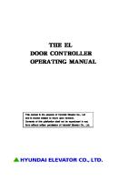
Figure 1: FSCurtis ICommand-Touch. The actual design of the membrane keyboard may vary from the one shown in this figure.
The ICommand-Touch is an intelligent compressor control system which can be extended. It can be used for oil-lubricated screw compressors with a fixed speed and for converter machines. Lento (oil-free) compressors can also be controlled with an extra module which extends the input / output level. The ICT also has a basic load cycle function to ensure equal utilization in up to five compressors at the same time (ICT as basic load cycle master with up to 4 basic load cycle slaves). All settings can be made via the graphic interface in the code-protected menu system. The base screen display provides a quick overview of the system type and status at all times. Extra information such as progression charts and compilations of all pressure and temperature values can be quickly accessed by simply tapping on them.
FSCurtis ICommand-Touch
V1.15
01.08.2016
7
2.2 Special versions There are two special versions of the software with slight deviations from the standard process. More information is available from FSCurtis on request.
2.3 Circuit diagram
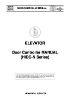
Figure 2: Rear view of control system (terminal assignment).
Pin
Designation
Function
Plug / grid
1
PE
Functional earth (EMC)
Phoenix
4
0V AC
Control system supply
MINI-COMBICON
5
18V AC .. 24V AC
6
Relay output A1 – 7 COM
Shared connection for
Phoenix
terminals 7 to 12
COMBICON
7
Relay output A 1
Mains contactor
8
Relay output A 2
Star contactor (freely programmable for FC)
Grid 3.81 mm, 3-pin
(fixed)
MSTBA Grid 5.0 mm
FSCurtis ICommand-Touch
V1.15
7-pin
01.08.2016
8 9
Relay output A 3
Delta contactor (freely programmable for FC)
10
Relay output A 4
Solenoid valve (with varistor, fixed)
11
Relay output A 5
Heating
12
Relay output A 6
Condensate valve (with varistor)
13
Relay output A 7 Normally closed contact
General fault
14
Phoenix COMBICON MSTBA
Relay output A 7 Common
Grid 5.0 mm 3-pin
15
Relay output A 7 Normally open contact
16
PE
Screen connection
17
GND
Ground for analogue inputs AE 2 and AE 3
Phoenix MINI-COMBICON Grid 3.81 mm, 6-pin
18
Analogue input AE 3
PT1000 (compressor temp.)
19
Analogue input AE 2
PT1000 (oil temperature)
20
Analogue input AE 1
4 – 20 mA (mains pressure)
21
24V DC
Transmitter voltage for AE 1
22
Dig. input E 8
Basic load cycle: loaded / idling
23
Dig. input E 7
Remote On/Off or basic load cycle OK
24
Dig. input E 6
Emergency stop (fixed)
25
Dig. input E 5
Speed limit
26
Dig. input E 4
Direction of rotation
27
Dig. input E 3
Overpressure
28
Dig. input E 2 (PTC)
Overcurrent
29
Dig. input E 1 (PTC)
Motor temperature
FSCurtis ICommand-Touch
V1.15
Phoenix MINI-COMBICON Grid 3.81 mm, 10-pin
01.08.2016
9 30
12V DC
Transmitter voltage 12V DC (PTC)
31
24V DC
Transmitter voltage 24V DC
32
GND
RS-485 standard
33
RS-485 B(-)
34
RS-485 A (+)
35
Not used
36
Signal B
37
Signal A
38
GNDX
39
0V AC supply bus module
40
18V AC supply bus module
36
- Analogue output 2
37
+ Analogue output 2
38
GNDx
39
+ Analogue output 1
40
- Analogue output 1
44
GND
45
RS-485 B(-)
46
RS-485 A(+)
47
Not used
Phoenix MINI-COMBICON Grid 3.81 mm, 4-pin
Option:
Phoenix
Interface for
Direct plug
MK200 bus modules
ZEC1.5/5-ST-5.0 5-pin
Option:
Phoenix
Connection for internal
Direct plug
analogue output module
ZEC1.5/5-ST-5.0 5-pin
RS-485 FU
Phoenix
(only with "Flex" variant)
MINI-COMBICON Grid 3.81 mm, 4-pin
2.4 Interfaces Description of interface functions will be added later.
FSCurtis ICommand-Touch
V1.15
01.08.2016
10
2.5 MK200 modules – assignment Depending on system type and configuration, additional MK200 modules may also be needed to extend the input/output level. (see also 4.6.2 ) Converter activation: MK200 4AA
address 1
only if FC activation is not performed via RS485
Basic load cycle module four
MK200 8E4RA
Address 2
to activate up to
compressors when connected via digital signals (generally external compressors) Accessories:
MK200 8E4RA MK200 8E4RA
Address 4 Address 5
Lento:
MK200 8E4RA
Address 6
Special version
MK200 8E4AE
Address 7
optional, non-system-dependent optional, non-system-dependent
only for special version
For configuration of modules, also refer to 4.6.2 and 4.6.3 .
Converter module MK200 4AA – Address 1 Analogue output 1
Current variable
Analogue output 2
Current variable
Basic load cycle module: MK200 8E4RA – Address 2 to activate up to four compressors when connected via digital signals (generally external compressors)
Lento: SCW module MK200 8E4RA – Address 6 This module cannot be configured and is always expected at address 6 on oil-free systems. The assignment of inputs/outputs is defined for Lento systems: Input 1 Fan 1 overcurrent Input 2 Fan 2 overcurrent Input 3 Converter fault Input 4 Dryer warning Input 5 Overfill. Maximum water level reached. FSCurtis ICommand-Touch
V1.15
01.08.2016
11 Input 6 Open water outlet Input 7 Water filter differential pressure Input 8 Bearing purging pressure build-up Output 1
Bearing purging solenoid valve
Output 2
Relief valve
Output 3
PU bearing
Output 4
Outlet valve (water drain)
MK200 4AE-4RA – Address 7 This module is always needed as soon as the ambient temperature monitoring is activated or a dryer is present and is always expected at address 7. The assignment of inputs/outputs cannot be changed: Analogue input 1 Not assigned Analogue input 2 Not assigned Analogue input 3 Dew point temperature (only if analogue input on AC P is occupied by oil temperature) Analogue input 4 Ambient temperature: if ambient temperature monitoring is active Output 1
Dryer
Output 2
Not assigned
Output 3
Not assigned
Output 4
Not assigned
Profibus module – Address 31 Can be activated in the menu.
FSCurtis ICommand-Touch
V1.15
01.08.2016
12
3 Using the control system
When you start the control system, a welcome screen as shown in illustration 3 is displayed for approximately three seconds. The display then automatically changes to the base screen display.
Figure 3: ICommand-Touch welcome screen.
The control unit has a resistive color touch screen with a resolution of 480x272 pixels. It is robust enough to cope with industrial use and is convenient and easy to use. The relevant control need simply be gently tapped – with a finger or stylus – for the desired input. The controls can also be used when wearing gloves.
FSCurtis ICommand-Touch
V1.15
01.08.2016
13
3.1 Display structure
Figure 4: Base screen display . (Note: For the purpose of illustration, this display contains a combination of symbols which is not possible in a real system.)
The following display elements are used in the user interface: Photo of system Tapping the photo or i-button in the title bar takes you to the system pass. If this symbol is shown in the system photo, it is a converter machine. Equipment status: The current status of the equipment is indicated by the following three icons which appear in the upper left-hand corner of all the display screens: the "Smiley" icon means no messages are present. The equipment is working correctly. as soon as a warning message or maintenance message is present, the "Smiley" is replaced by a warning triangle. the flashing tool indicates there is a fault. Messages are also shown in the system diagram, allowing the origin of the warning, maintenance or fault to be detected. Under the system diagram is the status line which continuously provides information about the system's operating status. The following symbols are used: Frost protection
FSCurtis ICommand-Touch
V1.15
01.08.2016
14
Heater on Load valve open Fan active Motor running Communication with RS485 active Pressure times timer active Compressor timer active SD card
Language selection: Press the button in the base screen display to select the language to be used in the displays. This button does not work in the current version.
Navigation: Tap the following buttons in the title bar to navigate through the system. Tap the "Home" button to return to the base screen display from any display screen (this button does not appear in the base screen display itself). Any code you have previously entered is rejected. Tap the left arrow to go back a screen or a level, depending on context.. Tap the right arrow to go to the next screen or level, depending on context.
Button bar in the base screen display: On the right-hand side of the base screen display you will find five buttons which you can use to access all the most important functions and information. These buttons have the following meanings (from top to bottom):
FSCurtis ICommand-Touch
V1.15
01.08.2016
15 Pressure:
The current mains pressure sensor measurement is displayed here. Tap this button to display the mains pressure progression as a graphic. All pressure values for the entire system are shown on the other pages (use arrow keys to page forwards and back).
Oil Temp:
The current final compression temperature measurement is displayed here. Tap this button to display the temperature progression as a graphic. All temperature values for the entire system are shown on the other pages (use arrow keys to page forwards and back).
Status:
The current compressor status is displayed. Tap this button to display the air circuit and oil circuit as a graphic.
Graphics:
This button takes you to an overview of all the graphic evaluations available. Mains pressure, temperature, maintenance intervals, utilization and basic load cycle are available (basic load cycle only when using the basic load cycle function).
Menu:
Click the "Menu" button to access the menu system. This is where you will find all the setting parameters.
Graphs The measurements for mains pressure and final oil compression temperature are saved regularly (for the intervals at which this data is stored, see 4.5.3 ). The data gathered in this manner can be shown as graphs. In the graph area, use one finger to drag a square to limit the amount of data displayed (zoom in). The following options are available on the x axis: Max
All the data points currently present are displayed. Both axes are adjusted to give the best possible display.
10 min, 30 min, 1 h The data at these time intervals is displayed. The direction keys scroll along the x axis in steps of a quarter of the selected interval. X-Auto
The values are taken from the Display Parameters → Graphs → X Auto menu.
Manual
Use this option to select and set your own date and time.
The y axis is initially scaled with values taken from the Display Parameters → Graphs menu. You can change both the upper and lower limit here. Use the numerical keypad to enter the new values. Tap the double-ended arrow on the y axis to reset the limits to the values taken from the menu.
FSCurtis ICommand-Touch
V1.15
01.08.2016
16
Figure 5: Graphical representation of temperature progression T1.
3.2 Messages
Figure 6: Popup messages in the base screen display.
When a new message arrives, you see a flashing warning triangle (warning/maintenance) or tool icon (fault) in the top left-hand part of the base screen display. The message also appears in plain text in a popup message box on the lower edge of the screen. Tap the Quit button to close the message window. However, the fault icon in the title bar continues to flash until the cause of the fault is dealt with. Tap the warning or fault icon in the title bar to display the plain text message again. You will find an overview of all the possible messages in Section 5 .
FSCurtis ICommand-Touch
V1.15
01.08.2016
17
3.3 Entering a code
Figure 7: Entering a code
Tap the Menu button in the button bar to open the code input screen. Here you see a number pad that you can use to enter the access code or the function code. Use the backspace key
to delete a code character by character.
Tap the Enter key to confirm the code. Tap the Home button in the title bar if you want to stop entering the code. When you confirm that a code is correct, the display switches to menu level, in other words, the associated function is carried out. There are codes with different functionalities:
Code
Code type
--- Menu
1 Menu
Access level Description / function No code
The menu system is displayed in full. You cannot change the settings. You can access the "Touch lock" function.
Customer
The menu system is displayed in full. Settings can only be made in the Display Parameters → Settings menu. You can access the "Touch lock" function.
FSCurtis ICommand-Touch
V1.15
01.08.2016
18 3846 Menu
Service
The menu system is displayed in full. You can change any of the parameters. Caution: As of the factory level, this code cannot be changed in the Configuration menu!
3.3.1 Accessing the menu system Once a menu code has been entered, the display switches to the main menu. Depending on code level, access is linked with various authorizations. Parameters are either just displayed or can also be modified. The more critical a setting is to the safety of the system, the higher the associated code level (see also Table 1). After commissioning and/or once ten operating hours are reached, the fixed service code is deactivated and replaced by a dynamically issued 24h code. The control system generates a random number and displays it. If this number is sent to Service/ FSCurtis, a day code, applicable for 24h, is provided. There is a separate code for specifically deactivating the fixed factory code, regardless of the operating hours counter.
3.3.2 Additional screenshot generation function The ICommand-Touch allows you to generate screenshots during operation, and save them on SD card. To do this, first enter the appropriate code (see Table 1), insert an SD card that is not write-protected, and ensure it is ready. To produce a screenshot, click on the title bar in the relevant display.
3.3.3 Commissioning functions To commission converter machines in the best possible way, you can run a run-in routine. To do this, first enter the appropriate code (see Table 1). Normal operation is not possible until the run-in phase is complete.
FSCurtis ICommand-Touch
V1.15
01.08.2016
19 If the run-in phase is interrupted, the appropriate cancel code must be entered. See also Table 1. During the run-in phase, the converter is run in at gradually increasing speed; 20s is spent in each step with a pause of two minutes between each step. The run-in routine is also activated if the converter setting is changed from "no" to "yes" in the menu.
3.3.4 Reset functions As well as the classic default setting, which resets the settings to their respective default values, there are other ways of resetting operating hours counters, error memories, graphics and switching cycles.
3.3.5 OEM functions These codes enable the branding to be changed from FSCurtis (standard) to Dalva, FSCurtis or Kraftmann. The control system's functionality remains exactly the same. However, the welcome screen and screen saver are displayed with the relevant logos and the choice of system types is adapted accordingly.
3.4 Inputting parameters All the parameters that can be changed appear with a button in the menus (see Illustration 8). If a value is display-only (cannot be changed), a field with a light blue background appears instead of the button.
Figure 8: Example of a menu. All the parameters displayed here can also be changed.
FSCurtis ICommand-Touch
V1.15
01.08.2016
20
Figure 9: Number pad for entering numerical parameters.
A number pad is provided to enter or change numerical parameters (see Illustration 9). It appears as soon as you tap the parameter value. To the left of the number pad you see the possible setting range, default (factory) setting, and a brief description. After you have input a new value, you can either accept or reject it:
Accept input and exit
Correct input Reject input and close input screen
FSCurtis ICommand-Touch
V1.15
01.08.2016
21
3.5 Software update If required, you can update the software on the ICT. To do so, switch it off (disconnect the power supply) and when you switch it on keep touching, any point on the touch screen. You can update the software from SD card or over the RS485 interface. RS485: To use the RS485 interface, you also need a computer with programming software and a USB-RS485 adapter. SD card: Insert the SD card with the required software in the control system and tap on the "Update Application (SD-Card)" button. The system displays all the files found. Select the software. Once the loading process is complete, you can restart the control system (switch it off, and then on again, or select "Start Application") CAUTION: Generally, settings remain unchanged. However, you should check them before you start the system again. If the original version is a non-approved test software (version number starts with V0.XX), you must reset the software to its defaults after you have performed the update. This will overwrite any settings that have previously been made.
FSCurtis ICommand-Touch
V1.15
01.08.2016
22
4 Menu system
The Main menu includes the following sub-menus: -
Control
-
Operating Parameters
-
Maintenance counter
-
Timer
-
Display settings
-
Configuration
-
Factory settings
-
Fault memory
-
Basic load cycle
-
Diagnosis
-
SD card
4.1 Control menu The menu contains the following parameters: Parameter
Values range/ Default setting/ Comments
System types
Code level
Switch-on pressure
Lower limit for pressure control.
All
Customer
All
Customer
All
Customer
Setting range: 3.5 bar – (shut-off pressure 0.1bar) Default setting: depending on system type
Shut-off pressure
Upper limit for pressure control. Setting range: depending on system type but at least 0.1 bar above switch-on pressure. Default setting: depending on system type
Switch-on
Lower limit for pressure control when switching
FSCurtis ICommand-Touch
V1.15
01.08.2016
23 Parameter
Values range/ Default setting/ Comments
Pressure 2
to the second pressure tolerance.
System types
Code level
All
Customer
All (only during slave basic load cycle mode)
Customer
FC
Customer
Setting range: 3.5 bar – (shut-off pressure 0.1bar) Default setting: depending on system type Shut-off pressure 2
Upper limit for pressure control when switching to a second pressure tolerance. Setting range: depending on system type but at least 0.1 bar above switch-on pressure. Default setting: depending on system type
Minimum pressure
If the mains pressure falls below the minimum pressure in basic load cycle mode (slave), a "Minimum pressure warning" is triggered. For as long as the warning is present / not acknowledged, the compressor switches to internal pressure control. Setting range: 3.5 bar – (shut-off pressure 0.1bar) Default setting: 0 bar (no minimum pressure monitoring)
Percentage target value
Only for frequency converter: Position of target pressure value within the current pressure tolerance. When the setting is "0 %", the target value is the switch-on pressure and when the setting is "100 %", it is the shut-off pressure. Intermediate settings apply correspondingly. Setting range: 0 to 100% Default setting: 50%
FSCurtis ICommand-Touch
V1.15
01.08.2016
24
4.2 Operating Parameters menu This menu includes the following parameters:
Parameter
Values range/ Default setting/ Comments
System types
Code level
Auto. restart
Automatic start after power outage.
All
Customer
All
Customer
All
Customer
All
Customer
Setting range: Yes / No Default setting: No Mode of operation
Mode of operation selection. Determines behavior when changing load. When loaded / idling, the motor runs continuously; in automatic mode, the motor is totally stopped if there is no load request (if necessary, under consideration of the overrun needed). Setting range: Automatic / Loaded / idling Default setting: Automatic
Remote On / Off
Defines whether it is possible to switch the system on/off remotely. If yes, it can be switched on/off using a digital input. If no, a correspondingly programmed digital input is ignored (also refer to 4.6.3 ) Setting range: Yes / No Default setting: No
Remote load / idling
Defines whether an external load request can be triggered by digital input. If yes, it can be switched on/off using a digital input. If no, a correspondingly programmed digital input is ignored (also refer to 4.6.3 ). With a basic load cycle slave, also defines whether activation is via digital inputs or RS485 interface. Setting range: Yes / No Default setting: No
FSCurtis ICommand-Touch
V1.15
01.08.2016
25 Dew point monitoring
Defines whether the dew point temperature monitoring is active and results in a warning or deactivation.
All
Customer
If dew point monitori ng is active
Customer
If dew point monitori ng is active
Customer
Setting range: Off, warning, fault Default setting: for Lento warning, otherwise off Max. dew point
Maximum permitted dew point temperature Setting range: 0°C – 50°C Default setting: 12°C If the "Max. dew point" threshold is set to 0°C, monitoring of the dew point temp. is deactivated!
Min. dew point
Minimum permitted dew point temperature Setting range: -10°C – 50°C Default setting: -4°C
FSCurtis ICommand-Touch
V1.15
01.08.2016
26
4.3 Maintenance/counter menu 4.3.1 Maintenance intervals This menu includes the following parameters:
Parameter
Values range/ Default setting/ Comments
System types
Code level
Water filter maintenance interval
Time interval in which the water filter is to be maintained.
Lento
Service
All
Service
All apart from Lento
Service
All apart from Lento
Service
All
Service
All
Service
Setting range: 0 – 30000 h Default setting: depending on system type
Maint. interval suction filter
Time interval in which the suction filter is to be maintained. Setting range: 0 – 30000 h Default setting: depending on system type
Oil/oil filter maintenance interval
Time interval in which the oil/oil filter is to be maintained. Setting range: 0 – 30000 h Default setting: depending on system type
Maint. interval oil separator
Time interval in which the oil separator is to be maintained. Setting range: 0 – 30000 h Default setting: depending on system type
Motor maintenance interval
Time interval in which the motor is to be maintained. Setting range: 0 – 30000 h Default setting: depending on system type
Compressor maintenance interval
Time interval in which the compressor is to be maintained. Setting range: 0 – 30000 h Default setting: depending on system type
FSCurtis ICommand-Touch
V1.15
01.08.2016
27 Parameter
Values range/ Default setting/ Comments
System types
Code level
Universal 1 maintenance interval
Freely usable maintenance interval. Name in Display parameters menu → Texts can be adjusted.
All
Service
All
Service
All
Service
Setting range: 0 – 30000 h Default setting: 0 h Universal 2 maintenance interval
Freely usable maintenance interval. Name in Display parameters menu → Texts can be adjusted. Setting range: 0 – 30000 h Default setting: 0 h
Universal 3 maintenance interval
Freely usable maintenance interval. Name in Display parameters menu → Texts can be adjusted. Setting range: 0 – 30000 h Default setting: 0 h
4.3.2 Counter menu
This menu includes the following parameters:
Parameter
Values range/ Default setting/ Comments
System types
Code level
Operating hours
Operating hours counter. (Motor on)
All
Factory
All
Factory
All
Factory
Setting range: 0 – 999999 h Default setting: 0 h
Loaded hours
Loaded hours counter. (Motor on, load valve open) Setting range: 0 – operating hours Default setting: 0 h
Stoppage hours
Stoppage hours counter. (System on, motor off) Setting range: 0 – 999999 h Default setting: 0 h
FSCurtis ICommand-Touch
V1.15
01.08.2016
28 Total delivery volume
Compressor delivery volume calculated from maximum delivery volume of compressor and load hours
All
Factory
Setting range: 0 – 999999999 m³ Default setting: 0 m³
4.4 Timer menu This menu includes the following sub-menus: −
Date/Time
−
Compressor switching times
−
Compressor pressure times
−
Digital outputs switching times
4.4.1 Date/Time The date and time can be set in this menu. The day of the week is automatically calculated and displayed. The automatic use of summer time can also be activated here. This takes account of the rules for using CET (Central European Time).
4.4.2 Compressor Switching Times The compressor's switch on/off times are defined in this menu.
FSCurtis ICommand-Touch
V1.15
01.08.2016
29
Figure 10: Compressor switching times. Start screen.
The timer can be fully (de)activated. If the "Compressor switching times" is set to "On", the compressor is only released at the programmed times. 8 switching times (channels 1 - 8) are available for programming. These channels are connected with an Or link, i.e. the compressor can only run if permitted by at least one channel. If the "Compressor switching times" is set to "Off", all time restrictions are cancelled. Individual channels can also be switched on/off. If a programmed channel is set to "inactive", it is not taken into account when evaluating the timer. The set times are, however, retained and can be activated if necessary. In the example shown below, the compressor would run at least Monday to Friday from 1 pm to 10.30 pm. To switch the compressor on continuously for one or more days, select the corresponding days and enter 00.00 as the switching times for all days.
Figure 11: Programming for channel 1.
FSCurtis ICommand-Touch
V1.15
01.08.2016
30
4.4.3 Compressor Pressure Times
Figure 12: Compressor pressure times. Start screen.
The timer can be fully (de)activated. If "Compressor pressure times" is set to "On", the compressor runs with the defined pressure tolerance for the programmed times. 8 channels are available for programming. The pressure tolerance of the first active channel that has a valid time programmed at that time always applies. If "Compressor switching times" is set to "Off" or if no channel is programmed for the current time, the compressor runs with the pressure tolerance set in the "Control" menu. Individual channels can also be switched on/off. If a programmed channel is set to "inactive", it is not taken into account when evaluating the timer. The set times and pressures are, however, retained and can be activated if necessary. In the example shown below, the compressor's pressure tolerance would be set to 8.5-9.5 bar at the weekend between 10.15 am and 10.30 pm. To switch a pressure tolerance for the compressor on continuously for one or more days, select the corresponding days and enter 00.00 as the switching times for all days.
FSCurtis ICommand-Touch
V1.15
01.08.2016
31
Figure 13: Programming for channel 1.
4.4.4 Outputs Switching Times The time frames for the digital outputs are programmed in the same way as the compressor switching times. There are four time frames available. These can be assigned to the digital outputs as required (also refer to Section 4.6.3 )
Figure 14: Four different time frames can be saved.
FSCurtis ICommand-Touch
V1.15
01.08.2016
32
Figure 15: Overview of channels in time frame 1. Channel 1 is active at present.
Figure 16: Programming of channel 1 in time frame 1.
4.5 Display parameters menu This menu includes the following sub-menus: −
Units / Offset
−
Diagrams
−
Texts
−
Screen saver
−
Lock screen
FSCurtis ICommand-Touch
V1.15
01.08.2016
33
4.5.1 Units / Offset
Parameter
Values range/ Default setting/ Comments
System types
Code level
Pressure unit
Display unit for all pressure values.
All
Customer
All
Customer
All
Customer
All
Service
All systems with dryer or activated dew point monitoring
Service
Setting range: bar, MPa, psi Default setting: bar Temperature unit
Display unit for all temperatures. Setting range: °C, °F, K Default setting: °C
Volume unit
Display unit for volumes / delivery volumes. Setting range: m³, ft³ Default setting: m³
Pressure offset
Offset from measured pressure value for display. Setting range: -0.5 – 0.5 bar Default setting: 0.0 bar
Dew point offset
Offset from measured dew point temperature for display. Setting range:-10 - 10°C Default setting: 0°C
FSCurtis ICommand-Touch
V1.15
01.08.2016
34
4.5.2 Texts Texts for the system pass can be entered in this menu using a QWERTY keyboard.
Parameter
Values range/ Default setting/ Comments
System types
Code level
Hotline
A service number can be saved here. It is displayed in both the system pass and the popup message box.
All
Service
All
Service
All
Factory
All
Factory
All
Factory
All
Service
All
Factory
26 characters are available. Default setting: no text stored Model
A free text with up to 16 characters can be stored here. Displayed in system pass. Default setting: no text stored
Factory no.
A free text with up to 10 characters can be stored here. Displayed in system pass. Default setting: no text stored
DP no.
A free text with up to 16 characters can be stored here. Displayed in system pass. Default setting: no text stored
Commission no.
A free text with up to 10 characters can be stored here. Displayed in system pass. Default setting: no text stored
Circuit diagram no.
A free text with up to 16 characters can be stored here. Displayed in system pass. Default setting: no text stored
Installation date
Generally the installation date is set automatically, but can be changed here manually if required (e.g. replacing a control system).
FSCurtis ICommand-Touch
V1.15
01.08.2016
35
4.5.3 Diagrams
Parameter
Values range/ Default setting/ Comments
System types
Code level
Save interval
Defines the recording interval for the progression diagrams.
All
Customer
All
Customer
All
Customer
All
Customer
All
Customer
Setting range: 1 – 60 s Default setting: 6 s X-Auto time period
Defines the time period of the progression diagram displayed when 'X-Auto' is selected. Setting range: 1 – 1440 min Default setting: 60 min
Mains pressure graph for Y axis at bottom
Defines the lower limit of the Y axis when the double arrow button (Y-Restore) is pressed in the mains pressure progression diagram. Setting range: 0.0 bar – Mains pressure graph for Y axis at top Default: 0.0 bar
Mains pressure graph for Y axis at top
Defines the upper limit of the Y axis when the double arrow button (Y-Restore) is pressed in the mains pressure progression diagram. Setting range: Mains pressure graph for Y axis at bottom – 16.0 bar Default setting: 10.0 bar
Temperature graph for Y axis at bottom
Defines the lower limit of the Y axis when the double arrow button (Y-Restore) is pressed in the temperature progression diagram. Setting range: -50°C – temperature graph for Y axis at top Default: 0 °C
FSCurtis ICommand-Touch
V1.15
01.08.2016
36 Parameter
Values range/ Default setting/ Comments
System types
Code level
Temperature graph for Y axis at top
Defines the upper limit of the Y axis when the double arrow button (Y-Restore) is pressed in the temperature progression diagram.
All
Customer
All
Customer
All
Customer
Setting range: Temperature graph at bottom – 150 °C Default setting: 100 °C Volume flow for Y axis at bottom
Defines the lower limit of the Y axis when the double arrow button (Y-Restore) is pressed in the volume flow progression diagram. Setting range: 0 m³/min – Volume flow for Y axis at top Default: 0 m³/h
Volume flow for Y axis at top
Defines the upper limit of the Y axis when the double arrow button (Y-Restore) is pressed in the volume flow progression diagram. Setting range: Volume flow for Y axis at bottom – 90.00 m³/min Default setting: Maximum delivery volume of system currently selected
4.5.4 Screen saver
Parameter
Values range/ Default setting/ Comments
System types
Code level
Screen saver active
Defines whether the screen saver function is active. If it is, the screen saver appears after the delay and if necessary is dimmed to the "Screen saver brightness". Touching any point on the screen removes the screen saver. The base screen display is then always displayed.
All
Customer
Setting range: Yes / No Default setting: Yes
FSCurtis ICommand-Touch
V1.15
01.08.2016
37 Parameter
Values range/ Default setting/ Comments
System types
Code level
Screen saver delay
This is where you define how long a screen remains active when not being used. After this period the display dims down to the "Screen saver brightness" value and the screen saver appears.
All
Customer
All
Customer
All
Customer
Setting range: 0 – 60 min Default setting: 5 min Standard brightness
Specifies the brightness of the display during operation. Setting range: 20 to 100% Default setting: 80%
Screen saver brightness
Sets the display brightness of an active screen saver. Setting range: 0 to 100% Default setting: 50%
4.5.5 Lock screen
You use this function to prevent someone from entering data accidentally when they are cleaning the display. The control system is locked for one minute and cannot be used after you start this function. This function works independently of the code level.
FSCurtis ICommand-Touch
V1.15
01.08.2016
38
4.6 Configuration This menu includes the following sub menus: • Communications • Heating/Ventilation • MK200 Modules • Inputs/Outputs • Compressor Type • Frequency Converter • CODE
4.6.1 Communications
Parameter
Values range/ Default setting/ Comments
System types
Code level
RS485 protocol
Defines the protocol type on the RS485 networking interface.
All
Service
All
Service
All
Service
All
Service
Setting range: MODBUS / Multimaster Default setting: RS485 address
Defines the participant address in the RS485 network. Setting range: 0 – 27 Default setting: 1
RS485 baud rate
Setting range: 4800 / 9600 / 19200 / 38400 / 57600 / 115200 Default setting: 19200
RS485 frame
Defines the protocol frame when networking via MODBUS. (Data bits/ parity/ stop bits) Setting range: 8/NONE/1 8/NONE/2 8/EVEN/1 8/ODD/1 Default setting: 8/NONE/1
FSCurtis ICommand-Touch
V1.15
01.08.2016
39 RS485 access
Defines the authorization for changes via the RS485 interface. Depending on the setting, either no parameters or only parameters of the corresponding code level can be changed.
All
Service/ factory
Depending on the code entered, not all settings are available Setting range: Read only Read / write, customer Read / write, service Read / write, factory Default setting: Read / write, service
FSCurtis ICommand-Touch
V1.15
01.08.2016
40
4.6.2 MK200 modules Various MK200 modules can be connected to the RS485 bus. Each module must have its own address and each address may only be used once. In principle, up to 32 participants are possible. The settings in this menu determine whether the ICT establishes communication with a module and monitors module presence and/or faults.
Parameter
Values range/ Default setting/ Comments
System types
Code level
MK200 Profibus
Defines whether a Profibus module is addressed on the MK200 module bus. Fixed address: 31.
All
Service
All
Service
Setting range: Yes / No Default setting: No No. of extension modules
Number of extension modules connected to the MK200 module bus. Addresses 9 to 30. Setting range: 0 – 22 Default setting: 0
Issuing of addresses: The addresses are set directly on the MK200 modules using Dip switches. The following addresses are intended for the modules and must be observed: Also refer to 2.5 . Address 0:
reserved – do not use.
Address 1:
MK200 4AA module for activating a frequency converter. Also refer to 4.6.6 .
Address 2
MK200 8E4RA module (basic load cycle module) to activate up to four basic load cycle slaves. Also refer to 4.10.2 .
Address 3
Do not use
Address 4-5
Up to two MK200 8E4RA modules as accessory modules 1 and 2. Inputs and outputs can be freely configured. Also refer to 4.6.3 .
Address 6
MK200 8E4RA module as SCW module (Lento). The inputs and outputs are permanently assigned. When a Lento system is selected, the module is expected and evaluated. Also refer to 4.6.3 .
Address 7
Do not use
Address 8
Only for special versions
Address 9-30 Up to 22 MK200 8E4RA extension modules. (Are not evaluated in this software!) Address 31
MK200 Profibus module
FSCurtis ICommand-Touch
V1.15
01.08.2016
41
4.6.3 Inputs/outputs Functions can be assigned to the digital inputs and outputs of the ICommand-Touch and accessory modules in this menu. The logic of the digital inputs can also be defined (NO or NC). There are eight digital inputs and seven digital outputs on the ICommand-Touch. Depending on default setting, these are preassigned as appropriate but can be changed if necessary. Depending on system type, outputs 1-4 of the ICommand-Touch may be permanently pre- assigned. There are another eight inputs and four outputs per accessory module. The operator is free to select how they are assigned. The logic can be defined for the inputs. Outputs can be linked with one of four time frames (timer; see Section 4.4.4 ). Functions available for the configurable digital inputs and outputs are listed in Tables 2 and 3.
Default setting for ICT digital inputs: Input 1 (inverted) PTC input: E073 Motor temp.(motor overtemperature fault) Input 2 (inverted) E074 overcurrent Input 3 E 075 overpressure Input 4 E072 direction of rotation and/or with Lento E099 water level Input 5 W033 speed limitation Input 6 E071 emergency stop Input 7
Remote on/off
Input 8
Remote load / idling
Default setting for ICT digital outputs: Output 1
Mains (cannot be changed!)
Output 2
Star (cannot be changed, free for FC systems)
Output 3
Triangle (cannot be changed, free for FC systems)
Output 4
Load valve (cannot be changed!)
Output 5
Ventilation
Combi T: Dryer
Output 6
Heating
Combi T: Condensate valve
Output 7
Collective fault
FSCurtis ICommand-Touch
V1.15
01.08.2016
42 Lento: SCW module address 6 (MK200 8E4RA) This module cannot be configured. The assignment of inputs/outputs is defined for Lento systems: Input 1 Fan 1 overcurrent Input 2 Fan 2 overcurrent Input 3 Converter fault Input 4 Dryer warning Input 5 Overfill. Maximum water level reached. Input 6 Open water outlet Input 7 Water filter differential pressure Input 8 Bearing purging pressure build-up Output 1
Bearing purging solenoid valve
Output 2
Relief valve
Output 3
PU bearing
Output 4
Outlet valve (water drain)
There are another eight inputs and four outputs per accessory module. The operator is free to select how they are assigned. The logic can be defined for the inputs. Outputs can be linked with one of four time frames (timer; see Section 4.4.4 ). The following functions are available: Digital inputs
Designation
Function
Free
Input is not evaluated
Local / remote
This input can be used to switch between local operation and remote control.
Remote On / Off
Remote On signal via digital input (is only evaluated if activated in the menu: see 4.2 )
Remote Load / Idling
Load request via digital input (is only evaluated if activated in the menu: see 4.2 )
Remote basic load cycle
Only relevant for basic load cycle master control. The basic load cycle master with all connected slaves can be activated/deactivated using this input. (Remote on/off for the entire station)
FSCurtis ICommand-Touch
V1.15
01.08.2016
43 Designation
Function
Basic load cycle - OK
Input for OK signal of a superordinate control system (is only evaluated if the control system is configured in the menu as basic load cycle slave: see 4.2 )
Pressure tolerance 2
Changeover to second pressure tolerance
Bridge timer
Timer is ignored if there is a signal at the input.
Room thermostat
The "Supply air flap open" and "Exhaust air flap closed" outputs are switched if there is a signal at the input.
Dew point dryer
The "High pressure dew point" output is switched if there is a signal at the input.
W025 heating W033 speed limitation W034 dryer W031 cond. drain W032 air filter W029 water filter W036 oil filter W037 oil separator W056 external warning 1 W057 external warning 2 W058 external warning 3 W059 external warning 4 E071 emergency stop E072 direction of rotation E073 motor temp. E074 overcurrent E075 overpressure E079 build-up of system pressure E099 water level E110 external fault 1 E111 external fault 2 E112 external fault 3 E113 external fault 4
A corresponding warning or fault message is triggered if there is a signal at the input.
Motor release
Depending on system type, not all the options stated may be available.
If there is no input signal, the motor does not run
Table 2: Possible functions for configurable digital inputs.
FSCurtis ICommand-Touch
V1.15
01.08.2016
44 Digital outputs
Designation
Function
Free
Output without function
On
Output always on if permitted by time frame.
Mains pressure too low
Output on if mains pressure too low
Ready
Output on if compressor ready
Loaded
Output on if compressor loaded
Idle mode
Output on if compressor idling
Motor on
Output on if motor running.
Fan on, flap open
Output on if fan running and flap open.
Supply air flap open
Output on if motor supply air flap open.
Exhaust air flap closed
Output on if exhaust air flap closed.
General fault
Output on if there is at least one fault.
Maintenance message
Output on if there is at least one maintenance message.
Warning message
Output on if there is at least one warning message.
Belt m. system pressure.
Output on if belt monitoring system pressure.
Pressure dew point high
Output on if pressure dew point too high
Dryer on
Output on if dryer on
Ventilation
Output on if ventilation active.
Heating
Output on if heating active.
Water supply
Output on if water supply active.
Coolant pump
Output on if coolant pump running.
Condensate valve
Output switches condensate valve.
Remote On
Output switches in parallel with Remote On digital input.
Table 3: Possible functions for configurable digital outputs.
FSCurtis ICommand-Touch
V1.15
01.08.2016
45
4.6.4 Heating / ventilation
Parameter
Values range/ Default setting/ Comments
System types
Code level
Coolant pump on at
switch-on threshold for the optional coolant pump.
Lento
Service
Lento
Service
Lento
Service
All apart from Lento
Factory
Systems with activated heating
Factory
Systems with activated heating
Factory
All
Factory
Setting range: Coolant pump off at – 60 °C Default setting: 52 °C Coolant pump off at
switch-off threshold for the optional coolant pump. Setting range: 0 °C – coolant pump on at Default setting: 49 °C
Coolant pump overrun
Overrun time for the optional coolant pump. Setting range: 0 – 5 min Default setting: 0 min
Heating
Defines whether the compressor has heating. If it does, the heating can either be controlled via the oil temperature or the final temperature. Setting range: No Final temperature Oil temperature Default setting: No
Heating switchon temp.
Defines the switch-on temp. for the heating (programmable output). Setting range: 2 °C – heating switch-off temp. Default setting: 5 °C
Heating switchoff temp.
Defines the deactivation temperature for the heating (programmable output). Setting range: Heating switch-on temp. – 80 °C Default setting: 8°C (Lento 7°C)
Recirculation
Recirculation protects against frost. Especially if there is no heating and/or for water-injected compressors. Setting range: No, Yes Default setting: No
FSCurtis ICommand-Touch
V1.15
01.08.2016
46 Parameter
Values range/ Default setting/ Comments
System types
Code level
Recirculation switch-on temp.
Defines the switch-on temp. for recirculation (compressor start without a request).
All
Factory
All
Factory
All
Factory
All systems with activated ventilation
Factory
All systems with activated ventilation
Factory
All
Factory
All systems with activated dryer
Factory
Setting range: 2°C – recirculation switch-off temp. Default setting: 5°C
Recirculation switch-off temp.
Defines the switch-off temp. for recirculation (idling without a request). Setting range: Recirculation switch-on temp. – 20°C Default setting: 15°C
Ventilation
Defines whether the compressor uses 2-point control for a fan. Setting range: No, Yes Default setting: No
Ventilation switch-on temp.
Defines the switch-on temp. for the fan (programmable output). Setting range: Ventilation switch-off temp. – 90 °C Default setting: 65°C (Lento 15°C)
Ventilation switch-off temp.
Defines the deactivation temperature for the fan (programmable output). Setting range: 0°C – ventilation switch-on temperature Default setting: 50°C (Lento 10°C)
Dryer
Defines whether there is a dryer and whether it is controlled (2-point control). Setting range: No, Yes Default setting: No (Combi T: yes)
Dryer switchon temp.
Defines the switch-on temp. for the dryer (programmable output). Setting range: Dryer switch-off temp. – 20 °C Default setting: 9°C
FSCurtis ICommand-Touch
V1.15
01.08.2016
47 Parameter
Values range/ Default setting/ Comments
System types
Code level
Dryer switchoff temp.
Defines the switch-off temperature for the dryer (programmable output).
All systems with activated dryer
Factory
All systems with activated dryer
Factory
All systems with activated dryer
Factory
All systems with activated dryer
Factory
All
Service
All systems with activated condensate valve
Service
Setting range: 0°C – dryer switch-on temperature Default setting: 1°C Dryer switchoff delay
Switch-off delay for dryer: when the temperature falls below the switch-off temperature, the dryer continues running for the set time. Setting range: 0 - 5min Default setting: 2.0 min
Dryer switchoff time
Minimum switch-off time for the optional dryer. Setting range: 30s - 600s Default setting: 300s
Dryer when system off
If "Yes" is set here, the dryer remains active when the system is not running (motor off). During continuous operation the temperature limits and set times are evaluated just as when not in continuous operation. Setting range: No / Yes Default setting: No
Condensate valve
Defines whether the condensate valve is activated. Setting range: Yes / No Default setting: No (Combi T: yes)
Condensate valve pulse time
Defines the condensate valve's switch-on temperature. Setting range: 1 - 99s Default setting: 3s
FSCurtis ICommand-Touch
V1.15
01.08.2016
48 Parameter
Values range/ Default setting/ Comments
System types
Code level
Condensate valve pause time
Defines the condensate valve's switch-off duration.
All systems with activated condensate valve
Service
Combi T
Service
Setting range: 1 - 999s Default setting: 120 s Condensate valve on at
When the condensate valve is to be activated can be defined here. Setting range: Dryer on loaded Default setting: Dryer on
4.6.5 System type
Parameter
Values range/ Default setting/ Comments
System types
Code level
Main type
Defines the compressor family for subsequent compressor selection.
All
Factory
All
Factory
Setting range depends on OEM type) VARIABLE FSCurtis VARIABLE GEAR DIRECT BELT FLEX LENTO COMBI COMBI-T
Dalva REGUL GERCULES TITAN NORMA APOLLO POLARIS OPTIMA OPTIMA-T
Kraftmann ALTAIR TAURUS SIRIUS VEGA CAPELLA CALLISTO PACK PACK-T
Default setting: -------Compressor selection
Defines the compressor. Caution! If this parameter is changed, the type-specific parameters are set to the relevant default settings. Default setting: --------
FSCurtis ICommand-Touch
V1.15
01.08.2016
49 Parameter
Values range/ Default setting/ Comments
System types
Code level
Frequency converter
Defines whether the motor is activated via a frequency converter or via star/delta.
All
Factory
All
Factory
All
Factory
If a switch is made here from "No" to "Yes", the converter run-in routine is started. Also refer to Section . Setting range: Yes / No Default setting: No Pressure range selection
Defines the maximum compressor pressure. Setting range: depending on system type Default setting: depending on system type
Maximum delivery volume
Defines the maximum compressor delivery volume. Setting range: 0 – 90.00 m³/min Default setting: depending on system type
4.6.6 Frequency converters
Parameter
Values range/ Default setting/ Comments
System types
Code level
Converter activation
Defines the connection type of the control system for the converter. Caution: If 'Analogue module, internal' is selected, all MK200 modules are deactivated.
FC
Factory
Setting range: Analogue module, internal Analogue module MK200 2AA Serial Modbus Default setting: Serial Modbus
FSCurtis ICommand-Touch
V1.15
01.08.2016
50 Parameter
Values range/ Default setting/ Comments
System types
Code level
Converter type
Defines the connected converter type.
FC
Factory
FC
Customer
FC
Factory
Setting range: YASKAWA EMOTRON ABB DELTA REXROTH Default setting: EMOTRON Minimum control range
Defines the minimum speed in relation to maximum speed. Setting range: 0 to 100 % Default setting: depending on system type
Limit temp. Speed-free.
Defines the temperature limit for the final temperature up to which the maximum speed is limited to the set value. Setting range: 0 to 100 °C
Not with Lento
Default setting: 0 °C Maximum speed limitation
Defines the maximum speed below the temperature limit entered in relation to the maximum motor speed entered. Setting range: 0 to 100 %
FC
Factory
Not with Lento
Default setting: 100% Control factor
Defines the controller gain.
FC
Service
FC
Service
FC
Factory
FC
Factory
Setting range: 1 – 999 Default setting: depending on system type Reset time
Defines the controller's reset time. Setting range: 0 – 999 s Default setting: depending on system type
Speed reduction from
Defines the lower pressure point from which the speed is reduced. Setting range: 0.0 bar - "Speed reduction to" Default setting: depending on system type
Speed reduction to
Defines the upper pressure point at which the speed is reduced by the stated value. Setting range: "Speed reduction from" - 16.0 bar Default setting: depending on system type
FSCurtis ICommand-Touch
V1.15
01.08.2016
51 Parameter
Values range/ Default setting/ Comments
System types
Code level
Speed reduction by
Defines the value (as a percentage) by which the maximum speed is reduced in the "Speed reduction to" point.
FC
Factory
Setting range: 0 to 100 % Default setting: depending on system type
4.6.7 Service code
The service code can be changed once the factory code has been entered. A code deviating from the standard code can therefore be defined. Setting range: 1 - 9999
4.7 Factory settings
Parameter
Values range/ Default setting/ Comments
System types
Code level
Switching cycle monitoring
Activate / deactivate switching cycle monitoring.
All
Service
All
Service
All
Factory
Setting range: Yes / No Default setting: Yes Max. switching cycles
When switching cycle monitoring is activated: maximum number of motor starts permitted per hour. Setting range: 1 – 60 /h Default setting: depending on system type
Ramp-up time
Defines the motor's ramp-up time. Setting range: 3 – 30 s Default setting: depending on system type
FSCurtis ICommand-Touch
V1.15
01.08.2016
52 Parameter
Values range/ Default setting/ Comments
System types
Code level
Stationary time
Defines the minimum overrun time when the compressor is deactivated manually. This value is used as a restart delay in the event of a power outage.
All
Service
All
Factory
All
FSCurtis
All
FSCurtis
All
FSCurtis
Lento
Service
Maximum delay before "Water filter differential Lento pressure" fault is triggered if signal is missing from appropriately configured input.
Service
Setting range: 0 – 120 s Default setting: 120 s Overrun time
Defines the compressor's overrun time in automatic mode and/or should the specified switching cycles be exceeded. Setting range: 10 – 3600 s Default setting: depending on system type
Min. final compression temperature
Defines the compressor's minimum start temperature. Setting range: 0 to 10 °C Default setting: 5 °C
Final compression temperature warn. Max. final compression temperature
Defines the upper warning threshold for the compressor's final temperature. Setting range: 90 – 115 °C Lento: 45 - 65°C Default setting: 105 °C Lento: 55°C Defines the upper deactivation threshold for the compressor's final temperature (fault). Setting range: 95 – 120 °C Lento: 50 - 70°C Default setting: 110°C Lento: 60°C
Bearing purging pressure buildup time
Maximum time for "Bearing purging pressure build-up". The fault message is delayed by 30s. Bearing purging and monitoring are only undertaken in "Standby". Setting range: 10 – 600 s Default setting: 45 s
Max. dif. Press. Wa. Filter
Setting range: 1 – 48h Default setting: 1 h Switch-on time
Opening time for relief valve after changing from loaded to idling.
Lento
Service
Setting range: 0 – 500 s Default setting: 70 s
FSCurtis ICommand-Touch
V1.15
01.08.2016
53 Parameter
Values range/ Default setting/ Comments
System types
Code level
Delayed for water max.
Delay for the "Overfill" signal
Lento
Service
Lento
Service
Lento
Service
All
Service
All
Service
All
Service
Setting range: 0 – 100 min Default setting: 1 min
Max. time water discharge
Maximum time for monitoring the "Water discharge" valve. If the water level is still too high after this time (digital input 5 at module addr. 6 max. water), fault message E100: max. water level is triggered. Setting range: 1 – 300 s Default setting: 180 s
Time for water supply
Time for which optional "Water supply" valve is open. Water supply output is activated when "Min. water level" digital input is triggered and system is loaded. Setting range: 0 – 180 s Default setting: 0 s
Ambient temperature
Defines whether the ambient temperature is monitored. If "Yes", the temperature sensor is expected at module addr. 7, analogue input 4. Setting range: Yes / No Default setting: No
Min. ambient temperature
Defines the lower deactivation threshold for ambient temperature. Is only displayed when ambient temperature monitoring is activated. Setting range: -50°C - "Max. ambient temperature" Default setting: -15°C
Max. ambient temperature:
Defines the upper deactivation threshold for ambient temperature. Is only displayed when ambient temperature monitoring is activated. Setting range: "Min. ambient temperature 100°C Default setting: 65°C
FSCurtis ICommand-Touch
V1.15
01.08.2016
54
4.8 Fault memory
Figure 17: Message memory for faults, messages and maintenance.
The last 20 messages are saved in the message memory. The most recent message is shown first. You have to scroll to older messages. The following information is provided for each entry: •
Entry number
•
Warning or fault symbol
•
Time when cause of message occurred
•
Message in plain text
Messages still live – i.e. not yet acknowledged – flash. Select a message to display more information. If present, the following sensor values that applied at the time the fault occurred are also displayed: •
Mains pressure
•
Compressor temperature
•
Oil temperature
•
Ambient temperature
•
Dew point temperature
The memory can be cleared by entering a corresponding code. This is not normally necessary. Once the message memory is full, each new message always takes the place of the oldest entry.
FSCurtis ICommand-Touch
V1.15
01.08.2016
55
4.9 Diagnosis The current statuses of the digital inputs and outputs of the ICommand-Touch can be found in this menu.
Figure 18: Diagnosis page for the ICommand-Touch.
If this page is selected with at least service code, the outputs can be activated and deactivated by tapping them. For reasons of safety, only one output can be active at any one time.
FSCurtis ICommand-Touch
V1.15
01.08.2016
56
4.10 Basic load cycle 4.10.1
Basic load cycle settings
Parameter
Values range/ Default setting/ Comments
System types
Code level
Basic load cycle
States whether and how communication is to take place for the basic load cycle function (and/or whether a basic load cycle module is present).
All
Service
All
Service
All
Service
Setting range: No (no basic load cycle) Digital (basic load cycle via additional module) RS485 (basic load cycle via RS485 networking) If "Digital" is selected, a basic load cycle module is expected at address 2 (see also 4.6.2 ). Default setting: No RS485 baud rate
Baud rate for communication with basic load cycle via RS485. Setting range: 4800 9600 19200 38400 57600 115200 Default setting: 19200
RS485 frame
Defines the protocol frame when networking via RS485. (Data bits/ parity/ stop bits) Setting range: 8/NONE/1 8/NONE/2 8/EVEN/1 8/ODD/1 Default setting: 8/NONE/1
FSCurtis ICommand-Touch
V1.15
01.08.2016
57 Parameter
Values range/ Default setting/ Comments
System types
Code level
Immediate change
Defines whether the basic load cycle order is rotated immediately after the change interval (recommended) or only once the activation/deactivation threshold is reached. Attention: if No is selected, the change interval may be greatly exceeded.
All
Service
All
Customer
All
Customer
All
Customer
All
Customer
Setting range: Yes / No Default setting: No Remote basic load cycle
Defines whether the entire compressor station controlled via the ICT – i.e. that of the basic load cycle master and all connected slaves - can be shut down. It is switched on/off via an appropriately programmed digital input: "Remote basic load cycle" (see 4.6.3 ) Setting range: Yes / No Default setting: No
Priority 1 change interval
Time between the basic load cycle switching further for the compressors with priority 1. Setting range: 1 – 168 h Default setting: 24 h
Priority 2 change interval
Time between the basic load cycle switching further for the compressors with priority 2. Setting range: 1 – 168 h Default setting: 24 h
Priority 3 change interval
Time between the basic load cycle switching further for the compressors with priority 3. Setting range: 1 – 168 h Default setting: 24 h
FSCurtis ICommand-Touch
V1.15
01.08.2016
58
4.10.2
Basic load cycle control
Parameter
Values range/ Default setting/ Comments
System types
Code level
Network volume
The manually calculated (or estimated) network volume can be entered here. Receivers and all compressed air lines must be taken into consideration. When using the internal network volume, the value entered here is also used as a start value for the calculation.
All
Customer
All
Customer
All
Customer
A start value is needed to calculate the network volume. On this basis, the actual network volume is calculated automatically during operations from the pressure progression and delivery volume. The value displayed here is however always an approximation. If a different start value is to be used, this must be entered in the "Network volume external" parameter. Value range: 0 – 99.9 m³ Default setting: 5.0 m³
Activation pressure
Defines the (lower) pressure threshold for activating a compressor. Setting range: 3.5 bar – (deactivation pressure - 0.1bar) Default setting: Switch-on pressure (from Control menu)
Deactivation pressure
Defines the (upper) pressure threshold for deactivating a compressor. Setting range: (Activation pressure + 0.1bar) – permitted maximum pressure of current system type Default setting: Switch-off pressure (from Control menu)
FSCurtis ICommand-Touch
V1.15
01.08.2016
59 Parameter
Values range/ Default setting/ Comments
System types
Code level
Percentage target value
Setting range: 1 – 99 %
All
Customer
Activation at
Defines the calculated utilization above which a control compressor is activated. Only if function is activated by setting a value greater than 0% for the "Deactivation at" parameter:
All
Customer
All
Customer
All
Customer
All
Customer
All
Customer
All
Customer
Default setting: 50%
Setting range: "Deactivation at" – 100 % Default setting: 100% Deactivation at
Defines the utilization above which a control compressor is deactivated if at least one other compressor is active. A setting of 0% deactivates this function. Setting range: 0% - "Activation at" Default setting: 0%
Activation damping initial activation
Defines the minimum time before the second compressor is activated (first compressor is activated instantly). Setting range: 0 – 600 s Default setting: 5s
Deactivation damping initial deactivation
Defines the minimum time before the second compressor is deactivated. (First compressor is deactivated instantly) Setting range: 0 – 60 s Default setting: 2s
Activation damping sequence switching
Defines the minimum time before further compressors (as of the third one) are activated (if the pressure continues to fall after activation(s)) Setting range: 1 – 600 s Default setting: 5s
Deactivation damping sequence switching
Defines the minimum time before further compressors (as of the third one) are deactivated (if the pressure continues to fall after deactivation(s)) Setting range: 2 – 60 s Default setting: 2s
FSCurtis ICommand-Touch
V1.15
01.08.2016
60 Parameter
Values range/ Default setting/ Comments
System types
Code level
Control factor
Setting range: 1 – 999
All
Factory
All
Factory
Default setting: 100 Reset time
Setting range: 0 to 999 s Default setting: 10s
4.10.3
Basic load cycle priorities
This menu contains the settings for the assignment of priorities for the individual compressors. The values set here only apply if none of the timer channels of the basic load cycle priorities timer are active.
Parameter
Values range/ Default setting/ Comments
System types
Code level
Compressor 1 - 5 priority
Defines a priority level for each compressor in the basic load cycle network. Preference is given to compressors with a high priority when activating. Basic loads are only changed between compressors of the same priority.
All
Customer
Setting range: Off (compressor is never activated) Low Normal High Default setting: Standard
4.10.4
Basic load cycle switching times
The basic load cycle's switch on/off times are defined in this menu. This only applies to the basic load cycle master. Programming is as described for the "Compressor switching times" in Section 4.4.2
FSCurtis ICommand-Touch
V1.15
01.08.2016
61
4.10.5
Basic load cycle pressure times
The basic load cycle pressure times are defined in this menu (raise / lower). This only applies to the basic load cycle master. Programming is as described for the "Compressor pressure times" in Section 4.4.3
4.10.6
Times for basic load cycle priorities
The switching times for changing the priorities of the basic load cycle are defined in this menu. This only applies to the basic load cycle master. Programming is as for other timers, for example "Compressor switching times" in Section .
Figure 19: Timer for changing over priorities for basic load cycle.
Figure 20: Page 1 of channel settings for times for basic load cycle priorities. The priorities for each of the switching times can be seen on page 2 of the channel (see Figure 21). The same priority levels as those defined under are available.
FSCurtis ICommand-Touch
V1.15
01.08.2016
62
Figure 21: Page 2 of channel settings for times for basic load cycle priorities.
4.10.7
Basic load cycle compressors
Parameter
Values range/ Default setting/ Comments
System types
Code level
Compressor designation
Change designation for selected compressor. 12 characters of free text are available.
All
Customer
All
Customer
All
Customer
Setting range: 12 characters of free text Default setting: Compr. X Maximum delivery volume
Defines the maximum compressor delivery volume. Attention! Note unit when transferring from type plate! Value range: 0 – 9000m³/min Default setting: 0
Minimum control range
Defines the compressor's minimum control limit. Below this limit, the compressor (only with FC) is deactivated. Value range: 0 - 100% Default setting: 100%
FSCurtis ICommand-Touch
V1.15
01.08.2016
63 Parameter
Values range/ Default setting/ Comments
System types
Code level
Loaded power output
Informs the ICT of the compressor's maximum power consumption.
All
Customer
All
Customer
Value range: 0 – 9999 kW Default setting: 0 kW Idling power output
Informs the ICT of the compressor's power consumption when idling. Value range: 0 – 9999 kW Default setting: 0 kW
4.11 SD card All functions with access to the SD card can be found in this menu. A corresponding card must be inserted in order to use them.
4.11.1
Saving parameters
The current set of parameters is written to the SD card. An SD card without write protection must be inserted. Caution: If data has already been saved on the inserted SD card, this is overwritten and therefore permanently lost. A set of parameters saved with this function can be read again using the "Load parameters" function. It doesn't matter which control system was used to save the data. A set of data can therefore be transferred to any number of control systems (with the same software version).
4.11.2
Loading parameters
This function can be used to read a set of parameters from the SD card. An SD card containing the file "ICTParam.par" must be inserted. Before the data is actually loaded, the storage date and system type of the set of data appear. Please check for plausibility first! Caution: When the data from the SD card is loaded, all current control system settings are overwritten and therefore permanently lost.
FSCurtis ICommand-Touch
V1.15
01.08.2016
64
4.11.3
Starting/stopping data logging
This function starts data logging to an SD card. An SD card without write protection must be inserted. The following data is also written: Date
Software version
12.08.14
System type
V1.07 DIRECT
Time stamp System status Mains pressure Final temperature Dew point temperature (only with Lento) Oil temperature (not with Lento) Delivery volume per hour Total delivery volume Ambient temperature (if configured) Statuses of all connected compressors (only with basic load cycle) Pressure, delivery volume and temperatures are each saved in the display dimension set on the control (bar/ psi/ Mpa, m³/ cft, °C/ °F/ Kelvin), statuses are saved in the set language. One file is created per calendar day in csv format (dividers: tabs). If data logging is running, the text on the button changes from Start data logging to Stop data logging. When this happens, an active data logging process can be stopped.
FSCurtis ICommand-Touch
V1.15
01.08.2016
65
5 Messages
5.1 Warning and maintenance messages When a new warning or maintenance message arrives, you see a flashing warning triangle in the top left-hand part of the base screen display. The message also appears in plain text in a popup message box on the lower edge of the screen. Tap the Quit button to close the message window. The warning triangle icon in the title bar stops flashing but remains present until the cause of the message is resolved. The message is displayed again by tapping the warning triangle.
Warning message
Comments
System types
W021: Compressor temp. increased
The maximum permitted final discharge temperature (warning limit) was exceeded. See Factory settings menu.
All
W022: Mains pressure increased
The mains pressure has exceeded the limit (maximum permitted mains pressure - 0.3 bar).
All
W023: Temperature low
The temperature has fallen below the minimum temperature needed for the start. See Factory settings menu.
All apart from Lento
W024: Lower pressure threshold
Pressure fallen below minimum pressure. Only relevant for basic load cycle slave mode. See Control menu.
All
W025: Check oil level/heating
Heating limitation warning: With heating activated, the "Overpressure fault" input has been triggered (delay of 0.5s).
All
W026: Calibration incorrect
At least one analogue input calibration value is incorrect.
All
W029: water filter
Water filter digital input warning has triggered.
Lento
W030: Water filter diff. pressure
Digital input 7 "Water filter differential pressure" at module addr. 6 was opened. Delay of 1s.
Lento
W031: Condensate drains
The digital input programmed at "W031: condensate drain" was closed.
All
FSCurtis ICommand-Touch
V1.15
01.08.2016
66 Warning message
Comments
System types
W032: Air filter
The digital input programmed at "W032: air filter" was closed. Warning triggered with 15minute delay
All
W033: Speed limit
The digital input programmed at "W033: speed limit" was opened. Delay of 1s.
All
W034: Dryer
The digital input programmed at "W034: dryer" was opened. Delay with Lento of 1s, otherwise no delay.
All
W035: Dew point dryer
The digital input programmed at "W035: dew point dryer" was opened. Only with activated dew point monitoring.
If module addr. 7 is present
W036: Oil/oil filter
The digital input programmed at "W036: oil/oil filter" was closed. Warning triggered with 15minute delay
All
W037: Oil separator
The digital input programmed at "W037: oil separator" was closed. Warning triggered with 15-minute delay
All
W038: Low dew point temp
During operation (motor running): Dew point too low. With dew point monitoring active, if set to "Warning". See also .
All
W039: High dew point temp
During operation (motor running): Dew point too low. With dew point monitoring active, if set to "Warning". See also .
All
W044: Extension module
At least one of the configured MK200 extension modules is not responding (possible addresses 9 to 30)
All
W045: I/O module (address 1)
The analogue output module at address 1 is not responding. This monitoring is only active when this module is activated (FC activation via external analogue module).
FC
W046: I/O module (address 2)
The basic load cycle module at address 2 is not responding. This monitoring is only active during basic load cycle master operation with digital activation of the basic load cycle slaves.
All
FSCurtis ICommand-Touch
V1.15
01.08.2016
67 Warning message
Comments
System types
W048: I/O module (address 4)
The accessories module at address 4 is not responding. This monitoring is only active when this module is selected.
All
W049: I/O module (address 5)
The accessories module at address 5 is not responding. This monitoring is only active when this module is selected.
All
W050: Profib. Mod.(addr. 31)
The profibus module at address 31 is not responding. This monitoring is only active when this module is selected.
All
W051: Overc. fan 1
Overcurrent at fan 1 (input 1, module addr. 6 was opened). But fan 2 is OK, delay 1s.
Lento
W052: Overc. fan 2
Overcurrent at fan 2 (input 2, module addr. 6 was opened). But fan 1 is OK, delay 1s.
Lento
W055: SD card access
An error has occurred when accessing the SD card.
All
W056: Ext. war. 1
The digital input programmed at W056: Ext. war. 1 was opened.
All
W057: Ext. war. 2
The digital input programmed at W057: Ext. war. 2 was opened.
All
W058: Ext. war. 3
The digital input programmed at W058: Ext. war. 3 was opened.
All
W059: Ext. war. 4
The digital input programmed at W059: Ext. war. 4 was opened.
All
Maintenance message
Comments
System types
M001: Intake filter
The time until the next maintenance is less than 100h.
All
M002: Oil/oil filter
The time until the next maintenance is less than 100h.
Not Lento
M003: Oil separator
The time until the next maintenance is less than 100h.
Not Lento
M004: Motor
The time until the next maintenance is less than 100h.
All
FSCurtis ICommand-Touch
V1.15
01.08.2016
68 Maintenance message
Comments
M005: Compressor
The time until the next maintenance is less than 100h.
All
M006: Dryer
The time until the next maintenance is less than 100h.
All
M007: water filter
The time until the next maintenance is less than 100h.
Lento
Universal maintenance 1
Also refer to Section 4.3.1 .The time until the next maintenance is less than 100h.
All
Universal maintenance 2
Also refer to Section 4.3.1 .The time until the next maintenance is less than 100h.
All
Universal maintenance 3
Also refer to Section 4.3.1 .The time until the next maintenance is less than 100h.
All
M012: Battery
The control system battery must be replaced.
All
System types
5.2 Fault messages When a malfunction report is received you see a flashing tool icon in the upper left-hand part of the base screen display. The message also appears in plain text in a popup message box on the lower edge of the screen. Tap the Quit button to close the message window. The malfunction icon in the title bar stops flashing but remains present until the cause of the error is resolved. Tap the icon in the title bar to call up the plain text message again. *A fault message will shut the computer off until corrected*
Error message
Comments
System types
E065: Power failure
The supply voltage has failed. (Only if "Automatic restart" is not programmed)
All
E066: Cable defect Compressor temp.
Final compression temperature measurement outside measurement range. Sensor defective or cable break.
All
E067: Cable defect oil temp.
Oil temperature measurement outside measurement range. Sensor defective or cable break.
All
E068: Cable defect pressure
Mains pressure measurement outside measurement range. Sensor defective or cable break.
All
FSCurtis ICommand-Touch
V1.15
01.08.2016
69 Error message
Comments
System types
E070: Cable defect dew point
Dew point temperature outside measurement range. Sensor defective or cable break.
All
E071: Emergency stop pressed
The emergency stop was pressed.
All
E072: Incorrect direction of rotation
Direction of rotation monitoring digital input opened. Delay of 250ms.
All
E073: Motor temperature
Motor temperature monitoring input opened. Delay of 1s.
All
E074: Overcurrent
Overcurrent monitoring input opened. Delay of 500ms.
All
E075: Overpressure
Overpressure monitoring input opened. Delay of 500ms.
All
E076: Switching cycle exceeded
Only with activated switching cycle monitoring.
All
E077: C. temperature too high
Final temperature too high. Temperature has exceeded set maximum temperature.
All
E078: Mains pressure too high
Mains pressure too high. Mains pressure has exceeded set upper limit.
All
E079: System pressure build-up
System pressure switch digital input has not yet opened after 35s of loaded operation.
All
E081: Converter fault
Converter fault digital input (input 3 at module addr. 6) has triggered (opened). Delay of 2s. Or communication fault with Yaskawa or Emotron converter.
Lento with FC
E090: Low dew point temp
During operation (motor running): Dew point too low. With dew point monitoring active, if set to "Fault". See also .
All
E091: High dew point temp
During operation (motor running): Dew point too low. With dew point monitoring active, if set to "Fault". See also .
All
E095: I/O module (address 4)
The additional module at address 4 (type MK200 8E4RA) is not responding. This monitoring is only active when this module is selected (see sections 4.6.2 and 4.6.3).
All
FSCurtis ICommand-Touch
V1.15
01.08.2016
70 Error message
Comments
System types
E096: I/O module (address 5)
The additional module at address 5 (type MK200 8E4RA) is not responding. This monitoring is only active when this module is selected (see sections 4.6.2 and 4.6.3).
All
E097: I/O module (address 6)
The Lento module at address 6 (type MK200 8E4RA) is not responding. This monitoring is only active if the system is a Lento system.
Lento
E098: I/O module (address 7)
The module at address 6 (type MK200 8E4RA) is not responding. This monitoring is only active if either the ambient temperature monitoring is activated or a dryer is expected at the module (= oil heater and dryer present at the same time)
All
E099: Water level
Water level low digital input has triggered. Delay for water supply 10s. For systems with water supply when loaded, delayed by the time set under "Water supply time".
Lento
E100: Max. water level
Water level too high (Max. water delay) digital input has triggered. And maximum drain time exceeded. Only monitored with motor running.
Lento
E101: Dif.press.water fi.
The "Differential pressure water filter warning" (digital input module addr. 6) has been active for longer than the time defined in the "Max. differential pressure water filter" parameter (see Operating parameters).
Lento
E103: Fan overcurrent
The two inputs "Fan 1 overcurrent" and "Fan 2 overcurrent" (inputs 1 and 2, module addr. 6) have triggered. Delay of 1s.
Lento
E106: Pres.bup.bear.press.
Bearing purging pressure build-up fault Digital input 8 at module addr. 6 has still not opened after the "Bearing purging pressure build-up" time set in the menu.
Lento
E110: Ext. fault 1
The digital input programmed at "External fault 1" has triggered.
All
E111: Ext. fault 2
The digital input programmed at "External fault 2" has triggered.
All
E112: Ext. fault 3
The digital input programmed at "External fault 3" has triggered.
All
FSCurtis ICommand-Touch
V1.15
01.08.2016
71 Error message
Comments
System types
E113: Ext. fault 4
The digital input programmed at "External fault 4" has triggered.
All
E120: FC overcurrent (OC,GF)
Only with Yaskawa converters. FC overcurrent fault
FC
E121: FC overvoltage (OV)
Only with Yaskawa converters. FC overvoltage fault
FC
E122: FC overload (OL2)
Only with Yaskawa converters. FC overload fault
FC
E123: FC overheating (OH1/2)
Only with Yaskawa converters. FC overheating fault
FC
E124: FC motor brake (RR,RH)
Only with Yaskawa converters. FC motor brake fault
FC
E125: FC feedback (FbL,FbH)
Only with Yaskawa converters. FC feedback fault
FC
E126: FC external (EF0-6)
Only with Yaskawa converters. FC external fault
FC
E127: FC hardware (OFx)
Only with Yaskawa converters. FC hardware fault
FC
E128: FC motor overload (OL1)
Only with Yaskawa converters. FC motor overload fault
FC
E129: FC connection (PGO)
Only with Yaskawa converters. FC connection (PGO) fault
FC
E130: FC interm. undervoltage (UV)
Only with Yaskawa converters. FC intermediate circuit undervoltage fault
FC
E131: FC underv. (UV1)
Only with Yaskawa converters. FC undervoltage fault
FC
E132: FC phase (LF,PF)
Only with Yaskawa converters. FC phase fault
FC
E133: FC communication (CE)
Only with Yaskawa converters. MEMOBUS communication error fault
FC
E134: FC control unit (OPR)
Only with Yaskawa converters. FC control unit not connected fault
FC
E135: FC motor I2t
Only with Emotron converters.
FC
E136: FC PTC
Only with Emotron converters.
FC
E137: FC motor off
Only with Emotron converters.
FC
FSCurtis ICommand-Touch
V1.15
01.08.2016
72 Error message
Comments
System types
E138: FC rotor blocked Only with Emotron converters.
FC
E139: FC ext. error
Only with Emotron converters.
FC
E140: FC mon max alarm
Only with Emotron converters.
FC
E141: FC mon min alarm
Only with Emotron converters.
FC
E142: FC com error
Only with Emotron converters.
FC
E143: FC PT100
Only with Emotron converters.
FC
E144: FC free
Only with Emotron converters.
FC
E145: FC pump
Only with Emotron converters.
FC
E146: FC ext mot temp Only with Emotron converters.
FC
E147: FC LC level
Only with Emotron converters.
FC
E148: FC brake
Only with Emotron converters.
FC
E149: FC option
Only with Emotron converters.
FC
E150: FC overtemp
Only with Emotron converters.
FC
E151: FC overcurrent F
Only with Emotron converters.
FC
E152: FC overvolt Vz
Only with Emotron converters.
FC
E153: FC overvolt G
Only with Emotron converters.
FC
E154: FC overvolt M
Only with Emotron converters.
FC
E155: FC overspeed
Only with Emotron converters.
FC
E156: FC underv.
Only with Emotron converters.
FC
E157: FC power error
Only with Emotron converters.
FC
E158: FC desat
Only with Emotron converters.
FC
E159: FC interm circuit error
Only with Emotron converters.
FC
E160: FC int. error
Only with Emotron converters.
FC
E161: FC overvolt MMax
Only with Emotron converters.
FC
E162: FC overv.
Only with Emotron converters.
FC
FSCurtis ICommand-Touch
V1.15
01.08.2016
73 Error message
Comments
System types
E173: Filter monitoring E174: Cable defect Mtemp. 1 E175: Cable defect Mtemp. 2
Only for special version
E176: Cable defect Mtemp. 3 E177: Cable defect ambient temp.
Ambient temperature measurement outside measurement range. Sensor defective or cable break.
All
Only with activated ambient temperature monitoring. E178: Min. ambient temp.
Ambient temperature too low. Ambient temperature has fallen below the set lower limit.
All
Only with activated ambient temperature monitoring. E179: Max. ambient temp.
Ambient temperature too high. Ambient temperature has exceeded the set upper limit.
All
Only with activated ambient temperature monitoring. E180: I/O module (address 8) E181: Motor not ready
Only for special versions
E182: Motor not running
FSCurtis ICommand-Touch
V1.15
01.08.2016
74
6 Version history of document
Date
Software version
author Comment
30/10/201 V0.14rc1 JR 2 15/10/2012
First version of the description
13/08/201 V1.07 JR 4 17/07/2014
Updated description without special versions. Description of RS485 interfaces still open.
28/03/201 V1.11 JR 5 16/03/2015
Description adapted to current software version: Changes include the following: −
Adjustable service code
−
Adjustable installation date
−
Dew point monitoring
−
Dew point offset for display
−
OEM Curtis introduced
−
Dryer switch-off delay, continuous operation
−
Condensate valve activation
Description without special versions. The software contains other changes which do not affect the description. 22/09/201 V1.12 JR 5 17/06/2015
FSCurtis ICommand-Touch
Description adapted to current software version: Changes include the following: −
Input and display of delivery volumes and volume flows in m³/min rather than m³/h
−
With FSCurtis branding, the display units are automatically changed to psi, °F and ft
V1.15
01.08.2016
75 22/09/201 V1.13 JR 5 20/07/2015
Occasional communication faults have been remedied and special software S04 has been prepared (acknowledge via digital input). The "Software update" section was added to this description.
28/09/201 V1.13 JR 5 20/07/2015
18/01/201 V1.14 RC2 BL 6 27/10/2015
Correction of typos on p37, p49 (comma in delivery volume)
- New "motor release" digital input - W023 suppressed during Power On - First activation/deactivation now refers to the second running and/or deactivating compressor, subsequent activation/deactivation to all others. - Default switching cycle monitoring to "On" - Default data logging to "On"
18/01/201 V1.15 BL 6 28/10/2015
FSCurtis ICommand-Touch
"Remote On" digital output issues the status of "Remote On" digital input.
V1.15
01.08.2016
Curtis-Toledo, Inc. 1905 Kienlen Avenue | St. Louis, Missouri 63133 www.fscurtis.com | [email protected]