![KobelionII-Vs ITCS Controller Manual [PDF]](https://pdfs.asia/img/200x200/kobelionii-vs-itcs-controller-manual.jpg)
8 0 2 MB
ITCS Controller Instruction Manual
[ For Service Shop ] This manual includes information not to open to the users. Careful handling in required.
ITCS CONTROLLER
Contents
1
Control Panel ............................................................................................................................................ 3
2
Lamp Indications on Control Panel......................................................................................................... 4
3
Operations of LCD Screen........................................................................................................................ 5
4
Start and Stop........................................................................................................................................... 6 4-1
Local start and stop (when Local is selected) ...........................................................................................................6
4-2
Remote start and stop (when Remote is selected)....................................................................................................6
5
Screen hierarchy....................................................................................................................................... 7
6
Main Menu Screen ................................................................................................................................... 8
7
Display of Running Condition.................................................................................................................. 9
8
Setup of Compressor Setting.................................................................................................................. 10 8-1
8-2
9
Setup of Compressor Setting 1................................................................................................................................ 11 8-1-1
The setting of pressure....................................................................................................................................................... 11
8-1-2
PID parameters setting...................................................................................................................................................... 11
Setup of Compressor Setting 2................................................................................................................................12 8-2-1
Pressure detection (OPTION) ............................................................................................................................................ 12
8-2-2
Pressure loss setting (OPTION) ........................................................................................................................................ 12
8-2-3
Dryer pre-operation ............................................................................................................................................................ 12
8-2-4
Dryer operate at fault......................................................................................................................................................... 12
8-2-5
Power failure (momentary) setting (Pwr return @ inst-out) ............................................................................................ 12
8-2-6
Power failure (long) setting (Pwr return @ block out and pwr start wait)...................................................................... 12
Weekly Timer Setup ............................................................................................................................... 13
10 Setup of Clock & Language.................................................................................................................... 14 10-1
Setup of Clock ..........................................................................................................................................................14
10-2
Language..................................................................................................................................................................14
10-3
Screen Saver ............................................................................................................................................................14
11 Display of Running Record .................................................................................................................... 15 11-1
Running record (every 5 second).............................................................................................................................15
11-2
Running record (every 1 hour) ................................................................................................................................16
11-3
Daily report..............................................................................................................................................................16
11-4
Weekly report...........................................................................................................................................................16
11-5
Error & Caution report............................................................................................................................................17 11-5-1 Contact status indication ................................................................................................................................................... 18 11-5-2 MINT / CAUT / EMS .......................................................................................................................................................... 19 11-5-3 Interlock List ...................................................................................................................................................................... 20
12 Display of Chart ..................................................................................................................................... 22 13 Display of Maintenance / Caution / Emergency Stop Information....................................................... 23 13-1
Display of Maintenance information ......................................................................................................................23
13-2
Display of Caution information...............................................................................................................................25
13-3
Display of Emergency stop information .................................................................................................................26
14 Sensor Error ........................................................................................................................................... 27 15 Yearly Maintenance................................................................................................................................ 28 16 Replacement of Battery.......................................................................................................................... 29
1
For Service Shop 17 Group Control Operation ....................................................................................................................... 30 17-1
2 compressors (VSII and VSI/II) operation.............................................................................................................30 17-1-1 Wiring of a compressor ....................................................................................................................................................... 30 17-1-2 Setup of a compressor......................................................................................................................................................... 30 17-1-3 Start and stop of a compressor .......................................................................................................................................... 30 17-1-4 Operation of a compressor.................................................................................................................................................. 31
17-2
2 compressors (AGⅡ and VSⅠ/Ⅱ) operation........................................................................................................32 17-2-1 Wiring of a compressor ....................................................................................................................................................... 32 17-2-2 Setup of a compressor......................................................................................................................................................... 32 17-2-3 Start and stop of a compressor .......................................................................................................................................... 32 17-2-4 Operation of a compressor.................................................................................................................................................. 32
18 Correspondence to a group control panel .............................................................................................. 34 19 Machine Spec. Setup .............................................................................................................................. 35 19-1
Model set ..................................................................................................................................................................36 19-1-1 Model setting ...................................................................................................................................................................... 36 19-1-2 Cooling type ........................................................................................................................................................................ 36 19-1-3 Drive type 1......................................................................................................................................................................... 36 19-1-4 Drive type 2......................................................................................................................................................................... 36 19-1-5 Pressure setting .................................................................................................................................................................. 36 19-1-6 CH scaling ........................................................................................................................................................................... 36 19-1-7 Remote com ......................................................................................................................................................................... 36 19-1-8 COM. Address ..................................................................................................................................................................... 36
19-2
CH scaling................................................................................................................................................................37
19-3
Timer setting............................................................................................................................................................38 19-3-1 Star-delta (Unused) ............................................................................................................................................................ 38 19-3-2 Load wait (Unused) ............................................................................................................................................................ 38 19-3-3 Actuating time of dryer solenoid valve.............................................................................................................................. 38
19-4
Counter setting ........................................................................................................................................................38
19-5
Option setting ..........................................................................................................................................................39 19-5-1 Startup power ..................................................................................................................................................................... 39 19-5-2 Ready to start...................................................................................................................................................................... 39 19-5-3 Emergency input................................................................................................................................................................. 39 19-5-4 Caution input ...................................................................................................................................................................... 39
19-6
Set up .......................................................................................................................................................................40 19-6-1 Group control ...................................................................................................................................................................... 40 19-6-2 System version.................................................................................................................................................................... 40 19-6-3 Inst-out start....................................................................................................................................................................... 40 19-6-4 Startup memory.................................................................................................................................................................. 40 19-6-5 Const-saving ....................................................................................................................................................................... 40 19-6-6 Default setting .................................................................................................................................................................... 40 19-6-7 Data reset............................................................................................................................................................................ 40
19-7
Zero setting ..............................................................................................................................................................41 19-7-1 Off set .................................................................................................................................................................................. 41 19-7-2 Sensor zero set .................................................................................................................................................................... 41
19-8
Inter lock setting......................................................................................................................................................42
19-9
Service monitor ........................................................................................................................................................43 19-9-1 External contact input indication...................................................................................................................................... 44 19-9-2 External contact output indication.................................................................................................................................... 45
2
ITCS CONTROLLER
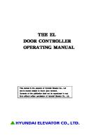
1 Control Panel ⑪ ⑩
⑫ ⑬ ⑭
② ⑤
①
⑮ ⑥
⑧
⑨
④ ③
⑯
⑦
1) LCD screen (liquid crystal display) The screen displays the running condition, condition setting and errors in the system.
9) “Power” LED lamp (green) This lamp indicates that the power to the ITCS controller is turned on.
2) Arrow keys ”↑” , ”↓” , ”→” , ”←” Arrow keys “↑”, “↓”, “→” are used to move the cursor, or increase or decrease the set values. Arrow key “←” is used to go back to the previous screen.
10) “Load” LED lamp This lamp indicates that the motor is running.
3) “Enter” key ・After entering a set value, press the “Enter” key for confirmation. ・If you press the “Enter” key on the item you have chosen (where the cursor is blinking), the related screen will be displayed.
11) “Auto Start” LED lamp (green) This lamp is lit while the weekly timer is on (when WEEKLY TIMER “ON” is selected). It also blinks when the compressor is stopped automatically due to discharge pressure exceeding the auto stop pressure (stop for volumetric control).
4) “Reset” key ・If this key is pressed when the cursor is sitting over a changeable item, the display will be put into the “Edit mode”. ・Emergency and Caution lamps can be reset.
12) “Emergency” LED lamp (red) This lamp indicates that the compressor is at an emergency stop due to a failure.
5) “BLANK” key (a round key surrounded by four arrow keys) If this key is pressed and held for 3 seconds or more, you can go back to the main menu screen.
13) “Caution” LED lamp (yellow) This lamp indicates that a caution has been given on the compressor.
6) “Remote/Local” key *Switchover while running is possible. This key is used to select Remote or Local mode for compressor start/stop. If Remote is selected, the “Remote” LED lamp (orange) will come on. If Local is selected, the “Local” LED lamp (green) will come on.
14) “Maintenance” LED lamp (orange) This lamp indicates that the maintenance time has come.
7) “Start” key If this key is pressed in the Local mode, the compressor will start.
15) “Stop” LED lamp This lamp indicates that the compressor is stopped.
8) “Stop” key If this key is pressed, the compressor will be stopped. (This switch operation is valid in both Remote and Local mode.)
16) “Start” LED lamp (green) This lamp indicates that the compressor is running.
* The lamps above indicate various operating status with lamps ON/OFF.
3
(green)
(red)
For Service Shop
2 Lamp Indications on Control Panel
L a m p i n d i c a t i o n (●:On、◎:Blinking) Status Maintenance
Caution
Emergency
Normal operation
Load
Start
●
●
Normal stop
Maintenance
Waiting to start after power’s coming back *1
Local
Remote
●
●
Emergency stop
Water removal operation
Auto Start
●
Caution
Maintenance LED has been on for 100 hours or more
Stop
●
●
●
◎
◎
●
●
Weekly timer ON
●
◎
●
Stop for volumetric control Unloading stop
●
◎
Two-units group control operation
●
◎
Local mode
●
Remote mode
●
*1) If power comes back within the allowable time, the compressor will start automatically in 60 minutes.
4
ITCS CONTROLLER
3 Operations of LCD Screen The operations of the LCD screen are all performed using four arrow keys, a round key surrounded by the arrow keys (called “BLANK” key), “Enter” key or “Reset” key.
This key is used to move the cursor across the selective items or the digits of the set value.
This key is used to move the cursor across the selective items, or increase the value in the digit selected in the edit mode.
This key is used to go back to the previous screen.
If this key is pressed when the cursor is sitting over the changeable item, the display will be put into the edit mode. In the edit mode, the set value can be changed using the arrow keys “→” and “↑” or “↓”. This key is also used to reset the Emergency/Caution lamp.
This key is used to confirm the set value changed in the edit mode. The related screen for the item chosen on the menu screen is displayed. This key is used to move the cursor across the selective items, or decrease the value in the digit selected in the edit mode.
・If this key is pressed and held for three seconds or more, the main menu screen will be displayed. ・If this key is pressed together with the “Enter” key, the machine spec. setup screen will be displayed. ・If this key is pressed together with the “Reset” key on the Yearly Inspection screen, the cursor will blink on O/RESET. (If the “Enter” key is pressed under this condition, the clock will be reset for yearly inspection.)
5
For Service Shop
4 Start and Stop To start or stop the compressor, any of the following methods is used.
4-1 ◇
Local start and stop (when Local is selected) Start and stop using “Start” key or “Stop” key on monitor control panel If the “Start” key is pressed, the compressor will start. If the “Stop” key is pressed, it will stop. * In the Local mode, the remote signals (remote start signal and remote stop signal) are ignored.
◇
Start and stop using weekly timer If WEEKLY TIMER “ON” is selected on the controller, up to seven patterns of start/stop time can be designated for auto start/stop. * See Chapter 9 for the setting of weekly timer.
4-2 ◇
Remote start and stop (when Remote is selected) Start and stop using Remote Start signal and Remote Stop signal The remote start signal (momentary normal open contact signal) starts the compressor. The remote stop signal (momentary normal close contact signal) stops it. * In the Remote mode, the compressor can be stopped by pressing the “Stop” key on the control panel.
6
ITCS CONTROLLER
5 Screen hierarchy The screens are structured as a tree, as shown below. Screen transition is made by pressing the arrow key and the “Enter” key. [ Power ON ] Opening screen A-0
(Displayed for the first 2 seconds, and then automatically changed to the main menu screen.) <Press and hold the BLANK key for 3 sec. or more.> (Note) A-7 indicates the screen number, but if it is shown at the left bottom of the actual screen, it will be replaced by AE-07.
Main menu screen A-1 ・Running condition
Running condition 1 screen A-2 Running condition 2 screen A-3
・Next ・Information of Maintenance /Caution/Emergency stop
Mainte./Caution/E-Stop menu screen A-8 ・Maintenance
Maintenance menu screen A-7 ・Clean dust filter
Action screen D-1
・Replace suc. filter
Action screen D-2
・Replace oil filter
Action screen D-4
・Replace oil element
Action screen D-5
・Inspect cooler
Action screen D-7
・Motor grease
Action screen D-9
・Replace battery
・Caution
Action screen D-3
・Replace lube oil
Action screen D-8
・Replace sensor
Action screen G-1
・Press loss high
Action screen D-16
Caution menu screen E-0 ・Discharge temp high
Cause screen E-1 ・Cause 1 - 6
・Oil separator temp high
Action screen E-3
・Dryer failure
Cause screen E-4 ・Cause 1 - 6
・Ambient temp high ・Oil separator clogged ・Motor coil temp
Action screen E-6 Causescreen E-10
・Sensor error
Action screen G-1
・INV - overheat
Action screen E-7
・INV - light error
Action screen E-9 Cause screen F-1 ・Cause 1 - 5
・Motor coil temp
Action 1 - 5 screen
Cause screen F-3 ・Cause 1 - 3
・Dryer failure
Action 1 - 5 screen
Cause screen F-2 ・Cause 1 - 5
・Fan motor current
Action 1 - 3 screen
Cause screen F-4 ・Cause 1 - 5
・Dis. temp high ・Oil sepa. temp high
Action screen F-7
・Water shortage
Action screen F-20
・Reverse phase
Action screen Fー21
・CPU error
Action 1 - 5 screen
Cause screen F-5 ・Cause 1 - 5
Action 1 - 5 screen
Action screen G-2
・Sensor error
Action screen G-1
・INV - error
Cause screen G-0 ・Cause 1 - 12
Action 1 - 12 screen
Setup of compressor setting 1 screen B-1 Setup of compressor setting 2 screen B-2
・Next
Setup of compressor setting 3 screen B-3
・Next ・Weekly timer setup
Action 1 - 5 screen
E-stop menu screen F-0 ・Motor over current
・Setup of compressor setting
Action 1 - 6 screen
Action screen E-5
・Cause 1 - 5
・Emergency stop
Action 1 - 6 screen
Weekly timer setup ON/OFF setup screen J-1
・Setup of clock & language ・Running record
Setup of clock & language screen B-8 Running record menu screen H-1 ・Record (every 5 sec)
Running record (every 5 sec) screen H-2
・Record (every 1 hour)
Running record (every 1 hour) screen H-3
・Daily report ・Weekly report ・E-stop & caution record ・Running record chart
Weekly timer setup screen J-2
Chart data selection screen M-1
Daily report screen H-4 Weekly report screen H-5 E-stop & caution record screen H-6 Chart data screen M-2
[ Press Enter and Blank key simultaneously ]
Password certified screen L-10
Password input = [111]
Setting menu screen L-0 ・Model set
Model set screen L- 1 ・CH scaling
・Timer set
Timer set screen L- 2
・Counter set
Counter set screen L- 3
・Option set
Option set screen L- 6
・Set up
Set up screen L- 7
・Zero set
Zero set screen L- 8
・Interlock set
Interlock set screen L-9
・Service monitor
Password input = [112]
7
H-7
Service monitor screen L- 4
CH scaling setup screen L- 5
For Service Shop
6 Main Menu Screen Following the tree shown on the preceding page will lead to any screen.
1)
If the main power is turned on, the screen shown in the figure on the right side (opening screen) will be displayed on the LCD (liquid crystal display) screen.
' 0 7/ 1 2/ 3 1
2 3: 5 9
0. 6 0
SCRE W
K- SYSTE M
AE - 0 0
MP a
C OMP R E S S OR
2 0 0 1
K OB E
STE E L
L TD.
Displayed during water removal running or remaining pressure release Discharge pressure
Current date & time ' 0 7/ 1 2/ 3 1
2)
The main menu screen will appear 2 seconds later, as shown in the figure on the right side.
2 3: 5 9
RUNN I NG
0 . 6 0 COND I T I ON
I N FORMA T I ON OF MA / CAUT I ON / EMER S E T U P O F COMP R E S S WE E KL Y T I MER SE TU S E TUP OF CLOCK &
If the “BLANK” key is pressed and held for 3 seconds or more on any screen, this screen will be displayed again.
RUNN I NG CHART
AE - 0 1
Screen No.
MP a
I NTENA GENCY OR SE T P LANGUA
NCE STOP T I NG GE
R E CORD
▲ ▼
MOV E MOV E
ENTER : SE L ECT
Key operation guidance
It shows that the current date and time on the upper left side of the screen, the discharge pressure on the upper right side, the version of the control program and the screen number on the lower left side, and the key operation guidance on the lower right side.
It cannot start in the state (0.5MPa or more) where the pressure in an oil recovery unit remains. It cannot start in the state where the pressure in an oil recovery unit remains. If starting operation is received in this state, it will be displayed as "Remaining pressure release”. It will start, if it waits to carry out a recovery unit pressure fall and becomes 0.5MPa or less. A message “Water removal running” will be shown in the upper center of the screen during water removal operation and purging. (They are displayed in the same locations on every screen.) Moreover, during water removal operation a compressor doesn’t stop automatically even if AUTO mode is selected.
8
ITCS CONTROLLER
7 Display of Running Condition On this screen, Running Condition can be monitored on the real time basis. 1)
This screen is displayed by selecting “RUNNING CONDITION” on the main menu screen with the arrow key “↓” or “↑”, and pressing the “Enter” key.
' 0 7/ 1 2/ 3 1
2 3: 5 9
RUNN I NG
0 . 6 0
I N FORMAT I ON O / CAUT I ON / S E T U P O F COM P WE E KL Y T I MER SE TUP OF CLOC RUNN I NG CHART
I NTENA GENCY OR SE T P LANGUA
▲ ▼
If the “Enter” key is pressed with the cursor on [NEXT], the Running Condition 2 screen will appear. On this screen, following can be monitored on the real time basis.
' 0 7/ 1 2/ 3 1
MOV E MOV E
GE
ENTER : SE L ECT
2 3: 5 9
RUNN I NG D I S O/ S D I S CUR AMB LOA RUN
CH P CH RE I E D I N I
A R A N N N N
RG E S RG T T G G
0 . 6 0
COND I T I ON
MP a
1
E PRE SSURE SURE E TEMPERATURE TEMPERATURE COND I T I ON HOUR
BACK 0 . 6 0 MP a 0 . 6 1 MP a 8 0 . 2 ℃ 6 0 A 2 0 . 4 ℃ 9 2 % 1 0 5 8 h r
[ NE XT ] ▲ ▼
AE - 0 2
' 0 7/ 1 2/ 3 1
RUNN I NG A L T A D R
F I c U R U
MOV E MOV E
ENTER : SE L ECT
2 3: 5 9
T . O/ S NE PRE TEMPE X . MACH A I N WA NN I NG
COND I T I ON
0 . 6 0 2
TEMPERATURE SSURE RATURE I NE COND I T I ON TER RAT I O COUN T . 3 0 0
・After oil separator temperature ・Line pressure (OPTION) ・Tc temperature (main motor coil temperature) ・Auxiliary machine condition AE - 0 3 (Speed ratio to rated fan speed) ・Drain water ratio (The tolerable quantity of drain water is displayed as 100%) Note) When the tolerable quantity of drain water exceed 100% and discharge pressure rises, water removal driving start. ・Running count (Start count)
MP a ・
7 8 . 0 0 . 6 0 6 9 . 4 6 0 6 0 0 0 0 0
By pressing the arrow key “←” on any screen the previous screen is displayed again.
9
NCE STOP T I NG
On the Running Condition 1 screen, following can be monitored on the real time basis. ・Discharge pressure ・Oil separator pressure (oil recovery unit inner pressure) ・Discharge temperature ・Current (input current) ・Ambient temperature ・Loading condition (Speed ratio to rated main motor speed) ・Running hour (accumulated time)
3)
F MA EMER RE SS SE TU K &
R ECORD
AE - 0 1
2)
MP a
COND I T I ON
BACK
℃ MP a ℃ % % t i me
For Service Shop
8 Setup of Compressor Setting The compressor is set up on this screen. 1)
This screen is displayed by selecting “SETUP OF COMPRESSOR SETTING ” on the main menu screen with the arrow key “↓” or “↑”, and pressing the “Enter” key.
' 0 7/ 1 2/ 3 1
2 3: 5 9
0 . 6 0
RUNN I NG
COND I T I ON
I N FORMAT I ON OF MA / CAUT I ON / EMER S E T U P O F COM P R E S S WE E KL Y T I MER SE TU SE TUP OF CLOCK & RUNN I NG CHART
I NTENA GENCY OR SE T P LANGUA
NCE STOP T I NG GE
R ECORD
▲ ▼
AE - 0 1
2)
MP a
MOV E MOV E
ENTER : SE L ECT
On the [SETUP OF COMPRESSOR SETTING 1] screen, following settings are possible. ' 0 7/ 1 2 / 3 1
2 3 : 5 9
SE TUP
・Keep pressure
OF
0 . 6 0
COMP R E S SOR
SE TT I NG
・Auto stop pressure
KEE P
PRESSURE
0 . 6 0
MP a
・Auto start pressure
AUTO AUTO
STOP PRE S . 0 . 6 5 START PRES . 0 . 5 5
MP a MP a
・PID setting
P I D
SE TT I NG
P =
2 6 0
I =
MP a
1
2 3 0
・
BACK
D =
0
[ NE XT ]
3)
・
For details, please refer to 8-1
BE - 0 1
If the “Enter” key is pressed with the cursor on [NEXT], the [SETUP OF COMPRESSOR SETTING 2] screen will appear. On this screen, following settings are possible.
' 0 7/ 1 2/ 3 1
(OPTION)※1
・Pressure loss setting
(OPTION)※1
・Dryer pre-operation ・Continuous operation at dryer fault ・Power return at inst-out ・Power return at block-out ※1
RESE T : RESE T ENTER : SE L ECT
OF
0 . 6 0
COMP R E S SOR
PRE SS DE TECT PRE SS LOSS SE T DRYER CONT I AT PWR R PWR R [ NE
MOV E : + MOV E : -
2 3: 5 9
SETUP
・Pressure detection
MO V E▲ ▼
PRE NUOU DRY E TUR E TUR XT ]
OPE S O ER N@ I N@B ・
BE - 0 2
R P F N L
AT ER AU ST OC
SE TT I NG
COM P 0 . 1 0 I A L K
M O V E▲ ▼
ON ON T I ON T ON OUT OUT
2
MP a ・
BACK
L I NE MP a OF F
OF F 0 . 5 s e c 0 . 0 s e c
MOV E : + MOV E : -
RE SET : RE SET ENTER : SE L ECT
: It is used when controlling line pressure.
For details, please refer to 8-2
4)
If the “Enter” key is pressed with the cursor on [NEXT], the [SETUP OF COMPRESSOR SETTING 3] screen will appear. On this screen, following settings are possible.
' 0 7/ 1 2/ 3 1 SE TUP
・Group control
・Initial charge
OF
GROUP
・Start select ・Slave diff pressure
2 3: 5 9 COM P R E S S OR
CONTROL
START SLAVE
SE L ECT
D I F F
I N I T I AL
PRE SS CHARGE ・
For details, please refer to Chapter 17
BE - 0 3
0 . 6 0
M O V E▲ ▼
SETT I NG
3
YE S
NO
MA S T E R
SLAVE
0 . 0 5
MP a ・
BACK
MP a 3
MOV E : + MOV E : -
分 RE SET : RE SET ENTER : SE L ECT
10
ITCS CONTROLLER
8-1
Setup of Compressor Setting 1 On this screen, following settings are possible. ' 0 7/ 1 2 / 3 1 SE TUP
2 3 : 5 9 OF
0 . 6 0
COMP R E S SOR
SE TT I NG
KEE P
PRESSURE
0 . 6 0
MP a
AUTO AUTO
STOP PRE S . 0 . 6 5 START PRES . 0 . 5 5
MP a MP a
P I D
SE TT I NG
P =
2 6 0
I =
2 3 0
1
MP a ・
BACK
D =
0
[ NE XT ] ・ BE - 0 1
8-1-1
MO V E▲ ▼
MOV E : + MOV E : -
RESE T : RESE T ENTER : SE L ECT
The setting of pressure (Keep Pressure / Auto Stop Pressure / Auto Start Pressure)
Auto stop/start pressure is pressure that stops/starts the motor when air consumption is extremely low, and the pressure increases even if the motor runs at the minimum speed. The pressure should be set as follows:
Auto stop pressure > Keep pressure > Auto start pressure The allowable pressure setting range is as shown in the table below.
8-1-2
Initial Setting
Min
Max
Keep pressure
0.60
0.54
0.80
Auto stop pressure
0.65
0.55
0.82
Auto start pressure
0.55
0.30
0.79
Keep pressure
…
It is the pressure made to follow uniformly.
Auto stop pressure
…
It is the pressure which makes a compressor stop automatically.
Auto start pressure
…
It is the pressure which makes a compressor start automatically.
PID parameters setting Under normal conditions, they do not have to change. Initial setting: P = 260, I = 230, D = 0
PID parameters are used to adjust discharge pressure fluctuation.
11
For Service Shop
8-2
Setup of Compressor Setting 2 On this screen, following settings are possible. ' 0 7/ 1 2/ 3 1 SETUP
2 3: 5 9 OF
0 . 6 0
COMP R E S SOR
PRE SS DE TECT PRE SS LOSS SE T DRYER CONT I AT PWR R PWR R [ NE
PRE NUOU DRY E TUR E TUR XT ]
OPE S O ER N@ I N@B ・
BE - 0 2
8-2-1
Pressure detection
R P F N L
AT ER AU ST OC
SE TT I NG
COM P 0 . 1 0 I A L K
ON ON T I ON T ON OUT OUT
M O V E▲ ▼
MOV E : + MOV E : -
2
MP a ・
BACK
L I NE MP a OF F
OF F 0 . 5 s e c 0 . 0 s e c RE SET : RE SET ENTER : SE L ECT
(OPTION)
Pressure to control is chosen. COMP LINE
8-2-2
: :
Pressure in a compressor Outside pressure
Pressure loss setting
(OPTION)
Setting of maintenance "PRESS LOSS SET" can be changed.
8-2-3
Dryer pre-operation Use this mode when there are some problems with the dew point in having the compressor and the dryer started at the same time.
8-2-4
ON
:
OFF
:
The dryer will be started first after the startup operation and the compressor and the compressor will follow three minutes later. The dryer and the compressor will start at the same time.
Dryer operate at fault Select [STOP] and stop the compressor due to the dryer's failure in the case where the frequencies of the instantaneous stop and the start and stop are small, the dryer's high pressure is difficult to be changed and the dew point performance is required strictly.
8-2-5
ON
:
OFF
:
If dryer fault occurs, the Caution lamp will come on and the dryer will be stopped, but the compressor will keep on running. Restart the dryer if the corrective actions are taken in three minutes after the dryer is stopped. If dryer fault occurs three times in one hour from the first occurrence, the dryer will not be restarted. If dryer fault occurs, the Emergency lamp will come on and the compressor will be stopped.
Power failure (momentary) setting (Pwr return @ inst-out) Initial setting: 0.5 sec (0.1 to 0.5)
If instantaneous interruption of not more than the specified duration, the compressor will not be stopped. Conversely, instantaneous interruption over the specified time will cause the compressor to stop. Note) If it is made a setup of "0sec", “the power failure (momentary) setting” will become invalid.
8-2-6
Power failure (long) setting (Pwr return @ block out and pwr start wait) Initial setting: 0.0 sec (0.1 to 20.0)
If instantaneous interruption of not more than the specified duration occurs, the compressor will be restarted automatically in 60 seconds after power recovery. Note) If it is made a setup of "0sec", “the power failure (long) setting” will become invalid.
12
ITCS CONTROLLER
9 Weekly Timer Setup Weekly timer is a function to automatically start and stop the compressor at the specified time. 1)
To use this function, move the cursor to “WEEKLY TIMER SETUP” on the main menu screen using the arrow key “↓” or “↑”, and press the “Enter” key.
' 0 7/ 1 2/ 3 1
2 3: 5 9
0 . 6 0
RUNN I NG I N FORMA /CA SE TUP O WE E K L Y SE TUP O
T I ON O UT I ON / F COM P T I MER F CLOC
RUNN I NG CHART
Move the cursor to “TIMER SETUP” using the arrow key “↓” and press the “Enter” key.
F MA EMER RE SS SE TU K &
▲ ▼
' 0 7/ 1 2/ 3 1
2 3: 5 9
WE E K L Y
T I ME R
I NTENA GENCY OR SE T P LANGUA
NCE STOP T I NG GE
R ECORD
AE - 0 1
2)
MP a
COND I T I ON
MOV E MOV E
ENTER : SE L ECT
0 . 6 0
MP a BACK
O
T I ME R
N
O
F
F
SE TUP
MOV E
▲ MOV E : + R E S E T : E D I T ▼ MOV E : - E N T E R : S E L E C T
J E - 0 1
The Weekly “TIMER SETUP” screen is as shown on the right side.
Seven patterns of start and stop can be set. Move the cursor to the item you want to change using the arrow key “↑”, “↓” or “→” and press the “Reset” key to enter the edit mode. Then select the desired value using the arrow key “↑” or “↓”, and press the “Enter” key for confirmation. Note) Start from AM/PM setting.
' 0 7/ 1 2/ 3 1 SE TUP ST 0 0 0 0 0 0 0
E P 1 2 3 4 5 6 7
2 3: 5 9 OF
0 . 6 0
WE E K L Y T I ME R S A P A P
MON MON WE D TUE
TA M M M M1
R 8 2 7 1
T : : : :
0 0 0 0
0 0 0 0
BACK
MON
J E - 0 2
S T OP PM 1: 0 0 PM 9: 0 0
NONE WE D
AM
6: 3 0
THU
PM
7: 0 0
NONE
MOV E
The day of the week can be changed using the arrow key “↑” or “↓” in the following order:
MP a
▲ MOV E : + R E S E T : E D I T ▼ MOV E : - E N T E R : S E L E C T
SUN → MON → TUE → WED → TUE → FRI →SAT → EDAY → NONE → SUN If “EDAY” is selected, the compressor is started and stopped at the same time every day regardless of the day of the week.
If arrow key “←” is pressed on the Weekly Timer Setup screen, the screen shown on the right side will be displayed again. The weekly timer function will be made available by entering the edit mode using the “Reset” key, moving the cursor to “YES”, and pressing the “Enter” key. In this case, the clock mark will be displayed on the left upper side of every screen. Note) The setup can be changed while running.
13
' 0 7/ 1 2/ 3 1
2 3: 5 9
WE E K L Y
T I ME R
0 . 6 0
MP a BACK
O
T I ME R
N
F
F
SE TUP
MOV E J E - 0 1
O
▲ MOV E : + R E S E T : E D I T ▼ MOV E : - E N T E R : S E L E C T
For Service Shop
10 Setup of Clock & Language
1)
This screen is displayed by selecting “SETUP OF CLOCK & LANGUAGE” on the main menu screen with the arrow key “↓” or “↑”, and pressing the “Enter” key.
' 0 7/ 1 2/ 3 1
2 3: 5 9
RUNN I NG I N FORMA /CA SE TUP O WE E K L Y SE TUP O RUNN I NG CHART
0 . 6 0 COND I T I ON T I ON O UT I ON / F COM P T I MER F CLOC
Move the cursor to the item to change using the arrow key “↑”, “↓” or “→”, and press the “Reset” key to enter the edit mode. Select the desired value using the arrow key “↑” or “↓”, and press the “Enter” key for confirmation.
F MA EMER RE SS SE TU K &
▲ ▼
' 0 7/ 1 2/ 3 1
I NTENA GENCY OR SE T P LANGUA
NCE STOP T I NG GE
R ECORD
AE - 0 1
2)
MP a
MOV E MOV E
ENTER : SE L ECT
2 3: 5 9
0 . 6 0
MP a ・
SE TUP
OF
CLOCK
Y
1 2
M
3 1
D
1 2
H
5 9
M
5 9
S
BE - 0 8
ENG
SAVER
J PN 1 5
M O V E▲ ▼
BACK
LANGUAGE
0 7
LANGUAGE SCRE EN
&
CHN
M I N
MOV E : + MOV E : -
RE SET : RE SET ENTER : SE L ECT
10-1 Setup of Clock The current year/month/date and time is set.
10-2 Language The language used throughout all screens can be selected, English or Japanese or Chinese. If the language selection is changed, the selected language is used in the following screens.
10-3 Screen Saver Initial setting: 15 minute (0 to 99)
The screen saver has a function to turn off the backlight when the screen is not operated for prolonged time, ensuring longer service life of the backlight. The time from the last key-in to the LCD screen backlight OFF is set. If any key is pressed after the backlight is turned off by the screen saver, the backlight will come on again. Note) The screen saver will become invalid if it is made a setup for "0 minute."
14
ITCS CONTROLLER
11 Display of Running Record
This screen is displayed by selecting “RUNNING RECORD” on the main menu screen with the arrow key “↓” or “↑”, and pressing the “Enter” key.
' 0 7/ 1 2/ 3 1
2 3: 5 9
0 . 6 0
RUNN I NG I N FORMA /CA SE TUP O WE E K L Y SE TUP O
MP a
COND I T I ON T I ON O UT I ON / F COM P T I MER F CLOC
RUNN I NG CHART
F MA EMER RE SS SE TU K &
I NTENA GENCY OR SE T P LANGUA
NCE STOP T I NG GE
R ECORD
▲ ▼
AE - 0 1
MOV E MOV E
ENTER : SE L ECT
The screen shows the following: ・Running record (every 5 sec.)
' 0 7/ 1 2/ 3 1
・Running record (every 1 hour) ・Daily report ・Weekly report
0 . 6 0
RUNNI NG
RE COR D
R E COR D R E COR D
( E VE RY ( E VE RY
MP a BACK
5 1
SE C) HOUR)
DAI L Y R E P OR T WE E K L Y R E P OR T
・Emergency stop and caution record To see the actual data, select the desired item using the arrow key “↑” or “↓”, and press the “Enter” key. The running record screen for the selected item will appear.
2 3: 5 9
E - S T OP
&
CAUT I ON
R E COR D
▲ MOV E ▼ MOV E
HE - 0 1
E NTER: SE L ECT
Note) On moving to each Running Record screen from the main menu, always press the “Enter” key.
11-1 Running record (every 5 second) The running data recorded every 5 seconds in the last 30 minutes is displayed. There are multiple pages for 5 second records. The desired page number can be selected using the arrow key “↑” or “↓”. To confirm the selection, press the “Enter” key.
The following running records can be checked. ・Discharge pressure ・Current ・Loading condition
' 0 7/ 1 2/ 3 1
2 3: 5 9
R UNNI NG R E COR D ( E VE R Y PAGE 0 ' 0 7/ 1 2/ 3 1 2 3: 5 9. 3 2 DI SCHARGE CURRE NT L OADI NG
HE - 0 2
15
PRE SSURE
CONDI T I ON
0 . 6 0 5
MP a
SE C)
0. 6 0
BACK
MP a
6 1
A
9 5
%
For Service Shop
11-2 Running record (every 1 hour) The running data recorded every hour in the last 24 hours is displayed. There are multiple pages for 1 hour records. The desired page number can be selected using the arrow key “↑” or “↓”. To confirm the selection, press the “Enter” key.
The following running records can be checked.
' 0 7/ 1 2/ 3 1
2 3: 5 9
0 . 6 0
R UNNI NG R E COR D ( E VE R Y PAGE 0 ' 0 7/ 1 2/ 3 1 2 3: 5 0. 3 4
・Discharge pressure ・Discharge temperature
D D C A
・Current ・Ambient temperature
I S I S UR MB
C C R I
H H E E
A A N N
RGE PRE SSURE R GE T E MP E R A T U R E T T T E MP E R A T U R E
1
MP a
HOUR )
0. 6 8 0. 6 2 0.
BACK
0 MP a 2 ℃ 1 A 5 ℃
HE - 0 3
11-3 Daily report Daily reports on the following items for the last 7 days can be checked. The desired page number can be selected using the arrow key “↑” or “↓”. To confirm the selection, press the “Enter” key.
The following daily reports can be checked.
' 0 7/ 1 2/ 3 1
2 3: 5 9
DAI L Y
・Running hour
(total running hours)
・Start & stop times
(total number of start & stop)
・Ambient temperature
(max of the day)
・Current
(max of the day)
・Loading condition
(average of the day)
0 . 6 0
R E P OR T PAGE
R S A D C L
UN TA MB I S UR OA
N R I C R D
I T E H E I
NG H & S T T RGE T G C
N A N N
MP a BACK
0
' 0 7/ 1 2/ 3 1
OUR T OP T I ME S E MP E R A T U R E PRE SSURE ONDI T I ON
1 2 3 1 5 2 0. 0. 6 4 9
0 2 3 0 9 0
h r T I ME ℃ MP a A %
HE - 0 4
11-4 Weekly report Weekly reports on the following items for the latest 5 weeks can be checked. The desired page number can be selected using the arrow key “↑” or “↓”. To confirm the selection, press the “Enter” key.
The following weekly reports can be checked.
' 0 7/ 1 2/ 3 1
2 3: 5 9
WE E K L Y
・Running hour
(total running hours)
・Start & stop times
(total number of start & stop)
・Ambient temperature
(max of the week)
・Discharge pressure
(max of the week)
・Current
(max of the week)
・Loading condition
(average of the week)
・Counter of error
(total number of occurrence)
R S A D C L C L
UN TA MB I S UR OA OU OA
N R I C R D N D
I T E H E I T I
0 . 6 0
RE P OR T PAGE 0
NG HOUR & S T OP N T T E MP ARGE PR NT NG COND E R OF E NG HOUR
BACK ' 0 7/ 1 2/ 3 1
T I ME S E RATURE E SSURE I T I ON R R OR
MP a
8 5 9 2 0. 0. 6 4 8
2 5 5 0 0 5 0 8 5 2
h r T I ME ℃ MP a A % T I ME h r
HE - 0 5
・Loading hour
16
ITCS CONTROLLER
11-5 Error & Caution report The detailed data taken every 5 seconds in 2 minutes and every 2 minutes in 30 minutes just before emergency stop are saved. The data of latest 4 emergency stops are displayed. Select AA or BB using the arrow key “→”, and select the page number or the error tracing number using the arrow key “↑” or “↓”. Note) After the screen is changed, always press the “Enter” key. ' 0 7/ 1 2/ 3 1
PAGE AA / BB AA: BB:
the page number (0 to 23) the error number back from the current error (0 to 3)
2 3: 5 9
ERROR & AGE 0 1 / 0 s 0 Ta d 6 9 0 Tc o 6 6 0 T3 4 0 Td 5 0 Ts T6 R U N T I ME : 3 2 0 0 0 0 0 h r D D P P P P P P
HE - 0 6
0 . 6 0
CAUT I ON RE PORT BA 1 ' 0 7 / 1 2 / 2 5 1 2 : 1 0 . 0 0 3 2 0 A 1 2 0 MN T : 8 0 0 * * * * * * * 0 P → 6 0 CAUT: 8 0 0 P ← 6 0 * * * * * * * 8 0 0 AO( V) 1 0 0 E MS : 0 * * * * * * * 0
I 1 O1
0 0 1 0 0 1 0 0 0 0 ▲ ▼
7
8
0 0 0 0 0 0 0 0 0 0 0 0 MO V E :+ MO V E :-
C
×0.1kPa
* * *
I 2 0 O2 0 :RE S : SE L
3
0 0 E E
0 1 0 0 T CT
(Unit) Td:Discharge temperature
×0.1℃
Pd:Discharge pressure
×000.1MPa
Ts:After oil separator temperature ×0.1℃
Po:Oil separator pressure
×000.1MPa
T6:Service temperature 2
P4:Service pressure 1
×000.1MPa
P5:Service pressure 2
×000.1MPa
×0.1℃
A:Current
A
Ta:Ambient temperature
×0.1℃
P→:Speed output
%
Tc:Motor coil temperature
×0.1℃
P←:Inverter data input
%
T3:Service temperature 1
×0.1℃
AO(V):FAN inverter voltage output
V
Note) Ps , P4 , P5 , T3 , T6 : Not used on the VS Series.
17
CK
0
0 D 0 D RE SE T ENTER
(Unit) Ps:Service pressure
MP a
For Service Shop 11-5-1
Contact status indication (1:Closed-ON , 0:Open-OFF)
Main inverter error pattern Bit3 Main inverter error pattern Bit2 Main inverter error pattern Bit1 Main inverter error pattern Bit0 Main inverter ON
(XD terminal)
Dryer failer
(XC terminal)
Suction filter clogged
(XB terminal)
Remote load instruction
(XA terminal)
Remote stop
(X9 terminal)
Remote start
(X8 terminal)
Unused Unused Unused Unused Unused Unused Water shortage relay (X1 terminal) Fan motor overload (X0 terminal) or Fan inverter error
DI1
0
0
0
0
0
0
0
0
0
1
0
1
0
DO1
0
0
0
0
1
0
0
0
1
1
0
1
0
Emergency
(Y0 terminal)
Caution
(Y1 terminal)
Maintenance
(Y2 terminal)
Remote selection
(Y3 terminal)
Running
(Y4 terminal)
Suction check solenoid valve
1
DI2
0
0
0
0
DO2
1
0
0
0
(Y5 terminal)
Purge solenoid valve (Y6 terminal) Dryer solenoid valve
(Y7 terminal)
Fan inverter running (Y8 terminal) Dryer run
(Y9 terminal)
Unused Oil supply solenoid valve
(YB terminal)
Unused
Main inverter run Unused Unused Main inverter error reset
For example, if the contact status indications are as shown above, it means that the main motor is running and the suction filter is clogged.
18
ITCS CONTROLLER 11-5-2
MINT / CAUT / EMS
Maintenance
Emergency
MNT :
EMS :
Unused
0
0
0
0
0
0
0
1
0
0
0
0
0
0
0
0
Dust filter cleaning intervals
0
0
0
1
Main motor over current
0
0
0
0
0
0
0
2
Suction filter change intervals
0
0
0
2
Main motor coil temp high
0
0
0
4
Oil filter change intervals
0
0
0
4
Reverse phase
0
0
0
8
Oil change intervals
0
0
0
8
Fan motor over current
0
0
1
0
Oil separator change intervals
0
0
1
0
Dryer error
0
0
2
0
Cooler inspection intervals
0
0
2
0
Discharge temp high
0
0
4
0
Monitor battery change intervals
0
0
4
0
Discharge temp high
0
0
8
0
Motor grease intervals
0
0
8
0
Oil separator temp high
0
1
0
0
Not used
0
1
0
0
Inverter ground fault
0
2
0
0
Not used
0
2
0
0
Inverter load open phase
0
4
0
0
Inspection (Maintenance)
0
4
0
0
Inverter main circuit DC voltage error
0
8
0
0
Pressure loss high
0
8
0
0
Inverter main circuit under voltage
1
0
0
0
Not used
1
0
0
0
Main motor overload
2
0
0
0
Not used
2
0
0
0
Inverter overload
4
0
0
0
Sensor error
4
0
0
0
Inverter step out
8
0
0
0
Not used
8
0
0
0
Inverter fuse burnt
Caution (Emergency is included in part.) CAUT : 0
19
Unused
0
0
0
0
0
(Bit0/1/2/3)
DI2
Unused
0
Inverter error
0
0
0
0
0
0
0
0
Normal
0
0
0
1
Discharge temp high
0
0
0
0
2
Discharge temp high
1
0
0
0
Ground fault
0
0
0
4
Oil separator temp high
0
1
0
0
Main circuit DC voltage error
0
0
0
8
Dryer error
1
1
0
0
Inverter contactor error
0
1
0
Main circuit under voltage
0
0
1
0
Ambient temp high
0
0
0
2
0
Oil separator element clogged
1
0
1
0
Motor overload
0
0
4
0
Inverter overheat
0
1
1
0
Inverter overload
0
0
8
0
Inverter light error
1
1
1
0
Over current
0
0
1
Inverter step out
0
1
0
0
Main motor coil temp high
0
0
2
0
0
Not used
1
0
0
1
Fuse burnt
0
4
0
0
(E-stop) Inverter error
0
1
0
1
Over torque
0
8
0
0
(E-stop) Water shortage
1
1
0
1
Load open phase
0
1
1
Inverter overheat
(E-stop)
(Caution)
1
0
0
0
(E-stop) CPU error
0
2
0
0
0
(E-stop) Sensor error
1
0
1
1
Inverter overheat
(Caution)
4
0
0
0
Maintenance alarm lasting for 100Hr
0
1
1
1
Inverter caution
(others)
8
0
0
0
Sensor error
1
1
1
1
Inverter error
(others)
For Service Shop 11-5-3
Interlock List
◇Emergency stop Location where failure is detected
Item
Detector
Condition1
Condition2
Thermocouple
155℃ or more, 3 minute continuation
160℃ or more, 5 second continuation
1
Motor coil temp high
Main motor coil
2
Main motor overload
Main inverter
Thermal
SW ON
3
Fan motor over load
Fan inverter
Thermal
SW ON
4
Dryer error
Dryer compressor
Thermostat
Dryer discharge
Pressure SW
Dryer motor
Thermal
SW ON
5
Discharge temp high
Oil separator
Thermocouple
110℃ or more
6
Oil separator temp high
After oil separator
Thermocouple
110℃ or more
7
CPU error
controller
“Cont. ope. At dryer fault OFF” selected
Controller
Dis. Thermocouple CH 9 O/S
thermocouple CH10
8
Main motor coil temp Thermocouple CH 7
Sensor error
Break Controller
Discharge pressure sensor CH 2
Zero error>5%
Inverter 9 10 11 12 13 14 15 16
Inverter ground fault (「GF」) Inverter main circuit DC volt error
(「PF」) Inverter contactor error (「UV3」) Inverter main circuit under voltage
(「UV1」) Inverter main motor overload (「OL1」) Inverter overload (「OL2」) Inverter over current (「OC」) Inverter step out (「STO」)
With no starting signal 1 minute
Inverter
Inverter
ground fault
Inverter
Inverter
Main circuit DC volt vibration
Inverter
Inverter
Contactor overheat
Inverter
Inverter
Volt 5 %
◇Maintenance Item
21
Location where failure is detected
Detector
Condition1
Condition2
Condition3
Running hour
1
Dust filter cleaning intervals
Running hour
Controller
2
Suction filter change intervals
Running hour or differential pressure
Controller
3
Oil filter change intervals
Running hour
Controller
6000Hr
4
Oil change intervals
Running hour
Controller
3000Hr
5
Oil separator change intervals
Running hour or differential pressure
Controller or Pressure sensor
6000Hr
6
Cooler inspection intervals
Running hour
Controller
6000Hr
7
Fill motor grease (Not used)
Running hour
Controller
8
Monitor battery change interval
Running hour
Controller
9
Sensor error
Pressure sensor
Pressure sensor
10
Yearly inspection
Running hour
Controller
11
Pressure loss high
Controller
Controller
500Hr Running hour
6000Hr
-6.2kPa
0.1MPa
Break Running hour
6000Hr Pressure loss > setting
A startup - one year or Yearly inspection - one year Dis. Pressure > rated pressure
2,4year+1year
For Service Shop
12 Display of Chart
This screen is displayed by selecting “CHART” on the main menu screen with the arrow key “↑” or “↓”, and pressing the “Enter” key.
' 0 7/ 1 2/ 3 1
2 3: 5 9
0 . 6 0
RUNN I NG I N FORMA /CA SE TUP O WE E K L Y SE TUP O
MP a
COND I T I ON T I ON O UT I ON / F COM P T I MER F CLOC
RUNN I NG CHART
F MA EMER RE SS SE TU K &
I NTENA GENCY OR SE T P LANGUA
NCE STOP T I NG GE
R ECORD
▲ ▼
AE - 0 1
MOV E MOV E
ENTER : SE L ECT
Two types of chart display are available: ・Real time ・Running record Any of the following items can be selected and displayed in either chart.
' 0 7/ 1 2/ 3 1
2 3: 5 9 CHART
ON T I ME RUNNI NG
0 . 6 0 D A T A -S E L E C T I O N
BACK
ON ON
R E COR D
DI S. PRES CURRE NT ROT . S P E E D
・Discharge pressure ・Current ・Rotating speed
MOV E
▲ MOV E ▼ MOV E
T I ME
[ DI S. PRE S]
ME - 0 1
On the Real Time screen, the real time data plotting starts at the time of screen change, and will stop when a chart for last 20-minutes data is completed. In the running record display, the hourly data in the last 24 hours are displayed in a chart.
MP a
' 0 7/ 1 2/ 3 1 [ MP a ] HI
2 3: 5 9 RE AL
RE SET: E DI T E NTER: SE L ECT
0 . 6 0
MP a BACK
L O 0 ME - 0 2
5
1 0
1 5
2 0 [ mi n ]
Note) The right most position in the real time display and the leftmost position in the running record display is the latest data.
22
ITCS CONTROLLER
13 Display of Maintenance / Caution / Emergency Stop Information
This screen is displayed by selecting “INFORMATION OF MAINTENANCE / CAUTION / EMERGENCY STOP” on the main menu screen with the arrow key “↓” or “↑”, and pressing the “Enter” key.
' 0 7/ 1 2/ 3 1
2 3: 5 9
RUNN I NG
0 . 6 0 COND I T I ON
I N FORMAT I ON O / CAUT I ON / S E T U P O F COM P WE E KL Y T I MER SE TUP OF CLOC RUNN I NG CHART
F MA EMER RE SS SE TU K &
▲ ▼
' 0 7/ 1 2/ 3 1
I NTENA GENCY OR SE T P LANGUA
NCE STOP T I NG GE
R ECORD
AE - 0 1
If MAINTENANCE, CAUTION or EMERGENCY STOP is selected using the arrow key “↑” or “↓” and the “Enter” key is pressed, the related screen to the selected item will be displayed.
MP a
MOV E MOV E
ENTER : SE L ECT
2 3: 5 9
0 . 6 0
MA I NT E NANCE / CAUT I ON / EMERGENCY STOP
MP a ・
BACK
I NFO .
MA I NT E NANCE CAUT I ON EMERGENCY
STOP
▲ ▼
AE - 0 8
MOV E MOV E
ENTER : SE L ECT
13-1 Display of Maintenance information The time to maintenance for the following is displayed. ・Clean dust filter ・Replace suction filter ・Replace oil filter ・Replace lube oil ・Replace oil element ・Inspect cooler ・Refill motor grease (Not used on the VS Series.) ・Replace battery ・Replace sensor ・Press loss high
' 0 7/ 1 2/ 3 1
2 3: 5 9
0 . 6 0
MA I NT E NANCE CL RE RE RE RE I N MO RE RE
E P P P P S T P P
AN LA LA LA LA PE OR LA LA
DUST F E SUC . E O I L E LUBE E O I L T COOL GREASE CE BATT CE SENS
C C C C C
AE - 0 7
' 0 7/ 1 2/ 3 1
I N FORMAT I ON R EMA I L TER : F I L TER : F I L TER : 1 O I L : 1 E L EMENT : 1 ER : 1 : 1 ERY OR PRE SS ▲ MOV E ▼ MOV E E N T E
2 3: 5 9
I 8 8 2 2 2 2 2
N 4 4 5 5 5 5 5
MP a
5 5 4 4 4 4 4
・ T I h h h h h h h
LOSS
CL RE BE WA CH RI ST
DE - 0 1
OGGE MOV E E I T TE R. E CK GHT OP C
0 . 6 0
MP a BACK
D
DUS T F I L T E R & CHE CK OI L L E VE L DUS T F I L T E R T HE N F I L T E R S HOUL D H E R V A C U U ME D OR CL E A N E D WI T H OI L L E V E L WH E T H P OS I T I ON. I F L E V OMP R E S S OR A N D S P R OGR E S S SVC. MOV E ▲ MOV ▼ MOV
E R L E E L I S UPPL Y 5 0 5 0 E : + R E : - E
Note) For initial setting of service (replacement) time, see the Compressor Instruction Manual.
23
H I
R : SE L ECT
MA I N T E N A N C E
The specific maintenance screen will be displayed automatically when the maintenance time comes. If the Maintenance screen is displayed automatically, perform maintenance following the instruction on the screen.
BACK ME r r r r r r r
VE L I L OW OI L . 2h r 0 0h r E SET: NTER:
S
/ RE SE T E DI T SE L ECT
For Service Shop Reset operation of the PROGRESS time After maintenance is completed, the PROGRESS time must be reset. To reset the PROGRESS time, move the cursor to 0/RESET using the arrow key “↑”, “↓” or “→”, and press the “Enter” key. This will reset the PROGRESS time to 0 hour. In addition, press the “Reset” key and make sure that the Maintenance LED lamp goes out. To set the PROGRESS time or the replacement time to the desired value, move the cursor to the target and press the “Reset” key to enter the edit mode. Then change the value using the arrow key“↑”or“↓”, and press the“Enter” key for confirmation.
' 0 7/ 1 2/ 3 1
2 3: 5 9
0 . 6 0
MP a
MA I N T E N A N C E CL RE BE WA CH RI ST
OGGE MOV E E I T TE R. E CK GHT OP C
DE - 0 1
BACK
D
DUS T F I L T E R & CHE CK OI L L E VE L DUS T F I L T E R T HE N F I L T E R S HOUL D H E R V A C U U ME D OR CL E A N E D WI T H OI L L E V E L WH E T H P OS I T I ON. I F L E V OMP R E S S OR A N D S P R OGR E S S SVC. MOV E ▲ MOV ▼ MOV
E R L E E L I S UPPL Y 5 0 5 0 E : + R E : - E
VE L I L OW OI L . 2h r 0 0h r E SET: NTER:
S
/ RE SE T E DI T SE L ECT
Note) For oil change intervals, see the Compressor Instruction Manual.
[Resetting the counter] Press the “BLANK” key and the “Reset” key at the same time to move the cursor to [0/RESET], and press the “Enter” key.
This will turn off the Maintenance lamp. Check the Maintenance lamp to make sure that the reset has been done properly.
24
ITCS CONTROLLER
13-2 Display of Caution information This screen is a menu screen where the types of caution are listed. To go to the specific caution information screen, select the desired item using the arrow key “↑” or “↓”, and press the “Enter” key.
' 0 7/ 1 2/ 3 1
2 3: 5 9
MP a
CAUT I ON D I S O I L DRY AMB O I L MOT SEN I NV I NV
CHA SE ER I EN SE OR SER -OV - L I
RGE PAR FA I T T PAR CO I ER ERH GHT
E E - 0 0
If the “Enter” key is pressed when the cursor is sitting over the item “DISCHARGE TEMP HIGH” on the above screen, the causes of the caution will be displayed, as shown in the figure on the right side. If there are two or more causes and the actions taken for them are different, the individual action screens can be displayed. However, if a caution is actually given, the screen as shown on the right side will be displayed automatically. If such a case, check the causes displayed on the screen and take proper actions.
0 . 6 0
' 0 7/ 1 2/ 3 1
BACK
TEMP H I GH ATOR T EMP LURE EMP H I GH A TOR C L OGG L TEMP ROR EAT ERROR ▲ MOV ▼ MOV
H I GH
ED
E E
ENTER : SE L ECT RE SE T : RE SE T
2 3: 5 9
0 . 6 0
MP a
CAUT I ON D I SCHARGE DUST F I L T AMB.T EMP PRS.SE TT O I L COOL O I L F I L T
1 2 3 4 5
D I S . TEMP
A I R
ER CL I S H I NG E ER CL ER CL 【
SE T
E E - 0 1
' 0 7/ 1 2/ 3 1
BACK
I S GE T T I NG OGG E D → I GH → RROR → O G G E D → OGG E D →
A A A A A
C C C C C
H I GH T T T T T
1 2 3 4 5
1 0 5 . 0℃ 】 1 0 6 . 0℃ ▲ MOV E E N T E R : S E L E CT ▼ MOV E R E S E T : R E S E T
2 3: 5 9
0 . 6 0
MP a
ACT I ON CL OGGE D DUSTF I L TE R
I S
BACK
DUSTF I L TE R
NE EDE D
T AK E OUT DUS T F I L T E R B Y B L OWI N G A I R F R OM
TO
CL E AN.
AND CL E AN I NSI DE .
I T
KE - 0 1
Note) If a caution is occurred and the remedial actions are taken, press the “Reset” key and make sure that the Caution lamp goes out.
25
For Service Shop
13-3 Display of Emergency stop information This screen is a menu screen where the types of emergency stop are listed. To go to the specific emergency stop information screen, select the desired item using the arrow key “↑” or “↓”, and press the “Enter” key.
' 0 7/ 1 2/ 3 1
2 3: 5 9
0 . 6 0
E ME R GE N C Y MOT MOT F AN DRY DI S OI L WA T RE V
OR OVE R OR COI L MOT OR E R F AI L . T E MP H SE PA. T E R S HOR E RSE PH
CURRE NT T E MP CURRE NT URE I GH E MP H I GH TAGE ASE
If the “Enter” key is pressed when the cursor is sitting over the item “DISCHARGE TEMP HIGH”, the causes of the emergency stop will be displayed, as shown on the right side. If there are two or more causes and the actions taken for them are different, the individual action screens can be displayed. However, if an emergency stop actually occurs, the screen as shown on the right side will be displayed automatically. In such a case, check the causes displayed on the screen and take proper actions.
CPU
' 0 7/ 1 2/ 3 1
I NV
DUSTF I PRES S T OO MA P OWE R MOT OR
L E N S F
T T Y U A
E R R OR
E R R OR
E NTER: SE L ECT RE SET: RE SET
0 . 6 0
E ME R GE N C Y MOT OR
ER TI N ST PPL I L U
CL G AR Y RE
MP a
S T OP
BACK
OVE R CUR R E NT
OGGE D E RR OR T & ST OP E RR OR
→ → → → →
▲ MOV E ▼ MOV E
F E - 0 1
' 0 7/ 1 2/ 3 1
E R R OR
2 3: 5 9
MA I N 1 2 3 4 5
BACK
SENSE R
▲ MOV E ▼ MOV E
F E - 0 0
MP a
S T OP
A A A A A
C C C C C
T T T T T
1 2 3 4 5
E NTER: SE L ECT RE SET: RE SET
2 3: 5 9
0 . 6 0
MP a
ACT I ON CL OGGE D DUSTF I L TE R
I S
BACK
DUSTF I L TE R
NE EDE D
T AK E OUT DUS T F I L T E R B Y B L OWI N G A I R F R OM
TO
CL E AN.
AND CL E AN I NSI DE .
I T
KE - 0 1
Note) If an emergency stop occurs and the remedial actions, such as repair and replacement, are taken, press the “Reset” key and make sure that the Emergency lamp goes out.
26
ITCS CONTROLLER
14 Sensor Error If a sensor error is detected, the Sensor Error screen will be displayed. On the screen, for which sensor the error is detected is shown by the cursor blinking on the application item. Check connectors for disconnection and harnesses for breakage. ' 0 7/ 1 2/ 3 1
2 3: 5 9
0 . 6 0
MP a
E RROR S E NS OR 1
CAL L CH 1 CH 6 CH 1 1
K OB E L CO CH 2 CH 7 CH 1 2
BACK
E R R OR
DI S T R I B UT OR . CH 3 CH 8 CH 1 3
CH 4 CH 9 ANS
GE - 0 1
CH 5 CH 1 0
RE SE T: RE SE T
Symbol of connector
Type of sensor CH1
P1
CH2
Discharge pressure sensor
(Pd)
P2
CH3
Oil separator pressure sensor
(Po)
P3
CH4
P4
CH5
P5
CH6
Ambient temperature sensor
(Ta)
T1
CH7
Main motor coil temperature sensor
(Tc)
T2
CH8
T3
CH9
Discharge temperature sensor
(Td)
T4
CH10
After oil separator temperature sensor
(Ts)
T5
CH11
T6
CH12
Current sensor
(A)
CT
CH13
Main inverter monitor signal
(P←)
R1
ANS
Main inverter answer (running) signal
(MCA)
V1
Note) CH1 , CH4 , CH5 , CH8 , CH11 , CH12 : Not used on the VS Series.
27
For Service Shop
15 Yearly Maintenance When yearly, 2-year or overhaul time comes, the Maintenance lamp comes on, and the MAINTENANCE screen will appear. Contact with the service shop if these indications come out. Unless reset operation is done (by the service shop), the MAINTENANCE screen will appear again 10 minutes after any other screen is displayed. ' 0 7/ 1 2/ 3 1
After counter reset
2 3: 5 9
0 . 6 0
YE ARL Y
MP a
I NS PE CT I ON
BACK
YE ARL Y
↓ 6000 running hours or one year
I NS P E CT OR CAL L DI S T R I BUT OR .
Display the yearly inspection
K OB E L CO
0/ RE SE T
DE - 1 0
[Resetting the counter] After the [YEARLY INSPECTION] screen above is displayed and maintenance is performed accordingly, the count starting date must be reset following the procedure shown below:
Press the “BLANK” key and the “Reset” key at the same time to move the cursor to [0/RESET], and press the “Enter” key.
This will turn off the Maintenance lamp. Check the Maintenance lamp to make sure that the reset has been done properly. If any other screen is displayed, press the “Reset” key to go back to the Maintenance screen.
28
ITCS CONTROLLER
16 Replacement of Battery The program and the data in the Controller are backed up by the lithium battery when the power supply is off. If the voltage of the battery lowers, “REPLACE CONTROLLER BATTERY” will be displayed. In such a case, replace the battery.
' 0 7/ 1 2/ 3 1
2 3: 5 9
0 . 6 0 MA I N T E N A N CE
RE PL ACE
CONT R OL L E R
CONT R OL L E R BA T T E R Y TO RE PL ACE . R E P L A CE CONT R OL L E R
I S
MP a BACK
BATTE RY NE E DE D.
BATTE RY.
DE - 0 8
RE SE T: RE SE T
[Replacement procedure] Remove 2 screws of the battery cover on the back of the Controller, as shown below. Now the battery can be taken out. The battery is connected to the circuit board with connectors (black). There are 2 battery connectors. When replacing the battery, be sure to connect a new battery to the free connector first, and then remove the old battery from the connector. If the old battery is removed first, all the setting data and running recode data will disappear. After the completion of replacement, tighten screws of the battery cover.
■
Precautions for handling batteries ■
・
Avoid short circuit of electrodes.
・
Do not put batteries into fire.
・
Charging is not possible.
・
Do not dismantle batteries.
・ Disposal must be done following the local regulations.
29
For Service Shop
17 Group Control Operation This automatic operation is available in the Local mode only. If GROUP CONTROL “YES” is selected on this screen, automatics alternate operation will be made possible using 2 compressors (without use of group control panel). ' 0 7/ 1 2/ 3 1 SE TUP
Keep in mind that operating methods differ with the combination of a compressor.
2 3: 5 9 OF
GROUP
COM P R E S S OR
CONTROL
START SLAVE
SE L ECT
D I F F
I N I T I AL
0 . 6 0
PRE SS CHARGE ・
BE - 0 3
M O V E▲ ▼
SETT I NG
3
YE S
NO
MA S T E R
SLAVE
0 . 0 5
MP a ・
BACK
MP a 3
MOV E : + MOV E : -
分 RE SET : RE SET ENTER : SE L ECT
17-1 2 compressors (VSII and VSI/II) operation Only by wiring for two units of the VSII, automatic alternate operation can be carried out. Slave unit will be started automatically if pressure becomes lower than AUTO START PRESSURE. Master will be stopped if pressure becomes higher than AUTO STOP PRESSURE and Slave turn into Master.
17-1-1
Wiring of a compressor The terminals within the starting boards of two compressors are wired mutually as follows. The follows serves as signals only for automatic alternate operation, and it differs from the usual. (It is impossible to take out the running output signal.)
VS II
VS I / II
X8 XA Y3 Y4 COM2 COM6
Y3 Y4 X8 XA COM6 COM2
Note) Before starting group control, make sure all wiring between compressors is correct.
17-1-2
Setup of a compressor The following setup is performed to compressor respectively.
17-1-3
(Refer to the setting example.)
1)
In the screen of COMPRESSOR SETTING, while setting of [GROUP CONTROL] as [YES], an item of [START SELECT] also sets as [MASTER] for the compressor and as [SLAVE] for another.
2)
It is confirmed that it is [Local mode]. (Local lamp: lighting) Note) It doesn't start in the Remote mode.
3)
The pressure setting is changed. Please set SLAVE DIFF PRESSURE setting to 0.01MPa or more. Please set to become "KEEP PRESSURE + SLAVE DIFF PRESSURE ≧ AUTO STOP PRESSURE".
Start and stop of a compressor Automatic alternate operation starts by pushing the "Start" button of MASTER. The group control changes from YES into NO by pushing the Stop button when the Group control is stopped.
30
ITCS CONTROLLER 17-1-4
Operation of a compressor
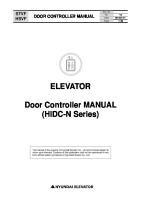
Normal operation 1) The Start lamp of both units lights when the Start button of MASTER is pushed, MASTER starts and SLAVE does the start standby. 2) After the initial air charging time of MASTER is over, if discharge pressure drops to less than AUTO START PRESSURE, SLAVE will be start up. *SLAVE doesn't start while the initial air charging time is operating. The discharge pressure of MASTER is set to become KEEP PRESSURE and the discharge pressure of SLAVE is set to become KEEP PRESSURE + DIFF. 3) MASTER stops automatically by AUTO STOP PRESSURE and does the change start standby to SLAVE. At this time, SLAVE also stops automatically and does the change start standby to MASTER. MASTER will be start automatically if discharge pressure drops to less than AUTO START PRESSURE. The operation of “3)” from “2)” is repeated.
When the failure occurs 1) When any failure occurs to MASTER unit during group control, SLAVE unit starts as MASTER. 2) When the breakdown is removed, the Reset button of MASTER is pushed, and the Start button is pushed. The breakdown unit starts as "MASTER", and SLAVE unit changes into "SLAVE". *The group control changes from YES into NO by pushing the Stop button if you want to stop the Group control.
[ Setting image ]
(MPa) 0.67 (0.60 + 0.07) ---● KEEP PRESSURE + SLAVE DIFF PRESSURE
● AUTO STOP PRESSURE -------- 0.65
○ AUTO STOP PRESSURE SLAVE DIFF PRESSURE (0.07MPa)
● KEEP PRESSURE --------------- 0.60
0.60
○ KEEP PRESSURE
● AUTO START PRESSURE ------ 0.58
0.58 ---------------------● AUTO START PRESSURE
________________________________________________ ( MASTER )
( SLAVE )
VS II
VS I / II
*1.Please carry out a setup of pressure to the same setup also as VS I and VS II. *2.Please set SLAVE DIFF PRESSURE setting to 0.01MPa or more. *3.Please set to become “KEEP PRESSURE + SLAVE DIFF PRESSURE ≧ AUTO STOP PRESSURE”.
31
For Service Shop
17-2 2 compressors (AGⅡ and VSⅠ/Ⅱ) operation By wiring for AG and VS, AG will serve as a backup machine of VS. If pressure becomes lower than AUTO START PRESSURE in the state where VS is operating, it will start automatically. And if pressure becomes higher than UNLOADING PRESSURE, it will stop. When AG unloads once, the unloading drive is continued until the LOADING CONDITION of VS becomes 90% or more, and the DISCHARGE PRESSURE becomes below the AUTO START PRESSURE besides.
17-2-1
Wiring of a compressor The terminals within the starting boards of two compressors are wired mutually as follows. The follows serves as signals only for automatic alternate operation, and it differs from the usual. (It is impossible to take out the running output signal.)
VS I / II
AG II
X8 XA Y3 Y4 COM2 COM6
Y3 Y4 X8 XA COM6 COM2
Note) Before starting group control, make sure all wiring between compressors is correct.
17-2-2
Setup of a compressor The following setup is performed to compressor respectively.
17-2-3
(Refer to the setting example.)
1)
In the screen of COMPRESSOR SETTING, while setting of [GROUP CONTROL] as [YES], an item of [START SELECT] also sets as [MASTER] for VS and as [SLAVE] for AG.
2)
It is confirmed that it is [Local mode]. (Local lamp: lighting) Note) It doesn't start in the Remote mode.
3)
The pressure setting is changed. Please set SLAVE DIFF PRESSURE setting to 0.00MPa. Please set to become “LOADING PRESSURE < KEEP PRESSURE < UNLOADING PRESSURE”.
Start and stop of a compressor Automatic alternate operation starts by pushing the "Start" button of VS. The group control changes from YES into NO by pushing the Stop button when the Group control is stopped.
17-2-4
Operation of a compressor
Normal operation 1) The Start lamp of both units lights when the Start button of VS is pushed, VS starts and AG does the start standby. 2) After the initial air charging time of VS is over, if discharge pressure drops to less than AUTO START PRESSURE, AG will start up. *AG doesn't start while the initial air charging time is operating. 3) AG will be unload running by UNLOADING PRESSURE. AG will be load running by AUTO START PRESSURE and the rotational speed 90% or more of VS.
32
ITCS CONTROLLER 4) After the inching inhibition of Master is over, AG stops automatically and does the start standby when the condition that it reaches UNLOADING PRESSURE continues for 3 minutes. *When the inching inhibition of Master is not over, it doesn't stop automatically. AG will start automatically if discharge pressure drops to less than AUTO START PRESSURE. The operation of “4)” from “2)” is repeated.
When the failure occurs 1) When any failure occurs to MASTER unit during group control, SLAVE unit starts as MASTER. 2) When the breakdown is removed, the Reset button of MASTER is pushed, and the Start button is pushed. The breakdown unit starts as "MASTER", and SLAVE unit changes into "SLAVE". *The group control changes from YES into NO by pushing the Stop button if you want to stop the Group control.
[ Setting image ]
(MPa)
● AUTO STOP PRESSURE -------- 0.70 0.68 ---------------------● UNLOADING PRESSURE ---------● KEEP PRESSURE --------------- 0.65 0.64 ● AUTO START PRESSURE ------ 0.60
● LOADING PRESSURE
LOAD / UNLOAD
0.60 ---------------------●AUTO START PRESSURE ----------
________________________________________________ ( MASTER )
( SLAVE )
VS I / II
AGⅡ
*1.Within initial charging time, SLAVE may not carry out continuation starting after an automatic operation start. *2.Please set SLAVE DIFF PRESSURE of AG setting to 0.00MPa. *3.Please set to become “LOADING PRESSURE < KEEP PRESSURE < UNLOADING PRESSURE”.
33
For Service Shop
18 Correspondence to a group control panel Initial setting: No
It sets up by “GROUP CONTROL
USE
' 0 7/ 1 2/ 3 1
NO" (L-07 screen).
2 3: 5 9
0 . 6 0
MP a ・
GROUP
CONTROL
SYSTEM VE RS I ON I NST -OUT START S T A R T U P MEMOR Y CONST - SAV I NG DE FAU L T SE TT I NG DATA RE SE T ・ L E - 0 7
MO V E▲ ▼
USE
NO
D N F Y
CON T RAM NO
I E L E
NO NO MOV E MOV E
SPLAY W ASH S
BACK
YE S YE S RE SE T : RE SE T ENTER : SE L ECT
◇ Correspondence to an established group control panel USE … Remote load instruction
ON OFF
: :
Full-load lock Loading / Unloading (Local pressure setting)
NO
ON OFF
: :
Full-load lock Unload lock
… Remote load instruction
When connecting with an established “Economild”, it sets up with "GROUP CONTROLL”USE”" there. USE … Remote load instruction
ON
:
Full-load lock
OFF
:
Loading / Unloading (Local pressure setting)
34
ITCS CONTROLLER
19 Machine Spec. Setup The machine spec. setup is allowed only at the factory setting and servicing. End users cannot use the function. 1)
Select the password certified screen by pushing “BLANK” key and “Enter” key at the same time. ' 0 7/ 1 2/ 3 1 ■
2 3: 5 9
0 . 6 0
SE TT I NG
MENU
■
MP a ・
BACK
Select the edit mode by pushing “Reset” key. 1 0 0
Next, decide the password by pushing “Enter” key after inputting the password [***] by pushing “↑” or “↓” key. After deciding the password, the service shop's menu screen is indicated by pushing “Enter” key once again. 2)
L E - 1 0
Change the menu screen into each screen which is set in detail. ' 0 7/ 1 2/ 3 1 ■
2 3: 5 9
0 . 6 0
SE TT I NG MOD E L S T I MER S COUNT ER OPT I ON SET UP Z ERO SE I NTER L SERV I CE
L E - 0 0
MENU
Model set
Timer set
Counter set Option set
Set up
Zero set Interlock set Service monitor
35
Model setting 1 Model setting 2 Cooling way Drive type 1 Drive type 2 Pressure CH scaling Remote com Com address Star-delta Load wait Dryer solenoid valve timer Load hour Unload hour Total running hour Running count Input-output Group control System version Inst-out start Startup memory Const saving Default setting Data reset Sensor zero set Service screen
MP a ・
BACK
E T E T SE T SET T OCK SE T MON I TOR ▲ ▼
MOV E MOV E
The items which are set by an each screen are in the following lists Setting item
■
Screen No.
L-01
L-02
L-03 L-06
L-07
L-08 L-09 L-04
ENTER : SE L ECT
For Service Shop
19-1 Model set The basic settings for objective machine are conducted on this screen. Model setting 1 Type Capacity 01 VS420A-22 02 03 VS730A-37 04 05 VS1020A-55 06 VS1500A-75 Model setting 2 Type Spec 01 STD
19-1-1
' 0 7/ 1 2/ 3 1
2 3: 5 9
0 . 6 0
MP a ・
MOD E L S E MOD E L S E COOL I NG DR I VE T DR I VE T PRE CH SC R E MOT COM . A D
TT I NG 1 TT I NG 2 TYPE YPE 1 YPE 2 SSURE A L I NG E COM DRE SS ・
L E - 0 1
M O V E▲ ▼
TY TY A I NO SE MP YE ON
PE PE R RM L F a S
BACK
0 1 0 1 WA T E R I NV PNL b a r NO OF F
1 MOV E : + MOV E : -
RE SET : RE SET ENTER : SE L ECT
Model setting
The machine’s setting is conducted by combining the setting 1 with the 2. The contents of the machine’s setting 1 and 2 are as follows. Note) Do not use except the setting ordered by the factory.
19-1-2
Cooling type Please always set up with "AIR".
19-1-3
Drive type 1
VS (inverter) setting [INV], AG (star-delta) setting [NORM] Note) The items of interlock and the signal of input and output change.
19-1-4
Drive type 2
In the case of using a separate installed starter panel, select [PNL].On the others, select [SELF] Note) The detection of the start jam, the start procedure and the signal of input and output change.
19-1-5
Pressure setting Select the pressure unit [MPa] and [bar] as to the pressure display.
19-1-6
CH scaling
CH scaling is to correspond the scale with the physical signal level of the pressure sensor, current sensor (CT) and speed signals from inverter. To change the scaling, select [YES] and press the “Enter” key. The scaling setup screen (L-5) will be displayed. Note) Always select [YES].
19-1-7
Remote com
Whether remote communication is required or not is set. Note) To make this setting possible, turn off the power and then turn on again.
19-1-8
COM. Address
To perform remote communication, different communication address must be set for individual compressors. The allowable setting range is 1 to 6. Note) To make this setting possible, turn off the power and then turn on again.
36
ITCS CONTROLLER
19-2 CH scaling The analog input ranges (for pressure sensor and current sensor) are set.
' 0 7/ 1 2/ 3 1 《
SCAL CH 1 L H CH 2 L H CH 3 L H CH 4 L H CH 5 L H
2 3: 5 9
I NG 》 OW I GH OW I GH OW I GH OW I GH OW I GH ・
0 0 0 . 1 5 . 0 . 1 5 . 0 . 0 . 0 . 1 5 . MOV
L E - 0 5
CH2 CH3 CH12 CH13
0 . 6 0
. 0 . 0 0 0 0 0 0 0 0 0 0 0 0 0 0 0 0 0 E▲ ▼
CH 1 2 CH 1 3 CH 1 4
L H L H L H
MP a
・ 0 3 0 0 0 1 0 0 0 0
OW I GH OW I GH OW I GH 2 0
3 0
4 0
BACK
CANCE L
1 0
5 0
A 0
MOV E : + MOV E : -
RE SE T : RE SE T ENTER : SE L ECT
VS420A-22
VS730A-37
VS1020A-55
VS1500A-75
0 15.00 0 15.00 0 221 22 107
0 15.00 0 15.00 0 138 19 106
0 15.00 0 15.00 0 89 18 107
0 15.00 0 15.00 0 68 19 107
LOW HIGH LOW HIGH LOW HIGH LOW HIGH
CH 2 :The range for the discharge pressure sensor is set. CH 3 :The range for the oil pressure sensor is set. CH12 :The range for the current sensor is set. CH13 :The range for the speed monitor is set. Note)
◇
CH1 , CH4 , CH5 , CH14
:
Not used on the VS series.
It cancels as an object for emergency operation, and the abnormalities in a sensor can be operated. If "0" under the number corresponding to the following sensor is set to "1", the sensor errors stop operating.
CANCE L
1 0
2 0
3 0
4 0
5 0
A 0
MOV E : + MOV E : -
RE SE T : RE SE T ENTER : SE L ECT
1 2 3 4 5 A
:discharge pressure sensor :No used :Line pressure sensor (option) :Motor coil temperature :Sensor error :All channels (CH1-5)
Although the abnormalities in a sensor may come out at the time of substitution of a sensor, please perform "SENSOR ZERO SET" after substitution. "Discharge temperature" and "after oil separator temperature" may lead to serious disaster, such as a fire, and cannot be canceled.
37
For Service Shop
19-3 Timer setting The setting of each action timers is conducted. ' 0 7/ 1 2/ 3 1
2 3: 5 9
0 . 6 0
MP a ・
STAR -DE L TA LOAD WA I T DRYER
SOL . VALVE
M O V E▲ ▼
・ L E - 0 2
7 s 2 s
/
BACK
1 0ms
OF F ON
2 5 4
MOV E : + MOV E : -
RE SE T : RE SE T ENTER : SE L ECT
19-3-1
Star-delta
(Unused)
19-3-2
Load wait
(Unused)
19-3-3
Actuating time of dryer solenoid valve
s s
The actuating time of dryer solenoid valve is in the following list. VS420A-22 VS730A-37 VS1020A-55 OFF ON OFF ON OFF ON 40
4
25
VS1500A-75 OFF ON
4
19-4 Counter setting Do not change except exchanging a controller.
Set each counter and timer.
' 0 7/ 1 2/ 3 1
2 3: 5 9
0 . 6 0
MP a ・
LOAD LOAD TOTAL
RUNN I NG RUNN I NG
・ L E - 0 3
BACK
HOUR .
3 0 0 0 0 0 0
H r
COUNT .
3 0 0 0 0 0 0
t i me
HOUR .
3 0 0 0 0 0 0
H r
COUNT .
3 0 0 0 0 0 0
t i me
M O V E▲ ▼
MOV E : + MOV E : -
RE SE T : RE SE T ENTER : SE L ECT
38
ITCS CONTROLLER
19-5 Option setting Do not change it in the case of no order from the factory. ' 0 7/ 1 2/ 3 1
2 3: 5 9
0 . 6 0
MP a ・
STARTUP
POW E R
STATUS
1 SHOT
TO
START
NO
EMERGENCY
I NPUT
NO
CAUT I ON
I NPUT
NO
USE 0 . 0 USE 0 . 0 USE 0 . 0
READY
・ L E - 0 6
19-5-1
M O V E▲ ▼
MOV E : + MOV E : -
BACK
SEC SEC SEC
RE SE T : RE SE T ENTER : SE L ECT
Startup power STATUS : The contact output of the starting order output (YA) is conducted by STATUS. (select usually) 1 SHOT : The contact output of the starting order output (YA) is conducted by 1 SHOT. (YA is off by MC answer back.)
19-5-2
19-5-3
19-5-4
39
Ready to start NO
: No option setting. (routine selection)
USE
: Use X12’s input terminal as the contact of the start condition from the outside. When [USE] is selected, X12 is ON and the compressor starts after passing the setting time of [***SEC].
Emergency input NO
: No option setting. (routine selection)
USE
: Use X14’s input terminal as the input contact of the Emergency stop from the outside. When [USE] is selected, the compressor makes emergency stop if X13 continues the setting time ON of [***SEC].
Caution input NO
: No option setting. (routine selection)
USE
: Use X13’s input terminal as the input contact of the Caution from the outside. When [USE] is selected, the compressor makes Caution action if X13 continues the setting time ON of [***SEC].
For Service Shop
19-6 Set up The significant operation is conducted as to the setting of the controller on this screen. ' 0 7/ 1 2/ 3 1
2 3: 5 9
0 . 6 0
MP a ・
GROUP
CONTROL
SYSTEM VE RS I ON I NST -OUT START S T A R T U P MEMOR Y CONST - SAV I NG DE FAU L T SE TT I NG DATA RE SE T ・ L E - 0 7
19-6-1
MO V E▲ ▼
USE
NO
D N F Y
CON T RAM NO
I E L E
NO NO MOV E MOV E
SPLAY W ASH S
BACK
YE S YE S RE SE T : RE SE T ENTER : SE L ECT
Group control
To perform altemate operation with two compressors only without using the group control panel, select “USE”. Note) For altemate operation of compressors, see Chapter 17 Group Control Operation.
19-6-2
System version
If the “Enter” key is pressed when the cursor is sitting over “DISPLAY”, the system version of the controller will be displayed on the lower left side of the screen as long as the “Enter” key is pressed. Note) The system version is a number to indicate the version of the hardware and OS (system program).
19-6-3
Inst-out start It sets the return action after the instantaneous stop. When [CONT] is set, it makes the return action by the time set by the [PWR RETURN @ INST-OUT] of the [Set up of compressor setting 2] screen.
19-6-4
Startup memory
The storage location of the control programs conducted at power supply input is designated. Note) Always select [FLASH].
19-6-5
Const-saving
Do not conduct on the spot because this operation is only conducted at the shipping from the factory. The values by the compressor's detail settings (all the settings on the L screen) are preserved in the area of the back up of the nonvolatile memory. (initial setting data's back up) Note) If this operation is conducted, just then, the default value (initial value) is changed as the above setting. Select [YES] from the [DEFAULT SETTING] on this screen, and the setting value preserved by this operation is returned.
19-6-6
Default setting
Return the setting on the L screen to all the default setting (initial values) by pushing the “Enter” key after selecting [YES]. Note) As far as the above mentioned [CONST-SAVING]-[YES] is not conducted, the default setting means the setting at the shipping from the factory.
19-6-7
Data reset The running time, the maintenance counter and the start frequencies are reset by pushing the ”Enter” key after selecting [YES]. The data through these operations are erased, the others except the setting value are returned in initial condition.
40
ITCS CONTROLLER
19-7 Zero setting The zero point adjustment of the sensor is conducted. ' 0 7/ 1 2/ 3 1
2 3: 5 9
S E NSOR
D I SCHARG O I L TAN SERV I C SERV I C
Z ERO
E K E E CU GENERAL S SE NSOR Z E R ・
L E - 0 8
19-7-1
0 . 6 0
PR PR PR PR RR I G O
E E E E E N S
S S S S N A E
MO V E▲ ▼
ADJUST OF FSE T S S S S T L T
. . . 1 . 2
MOV E MOV E
0 0 0 0 0 0 YE S
MP a ・
BACK
D I SP 0 0 0 0
. . . .
0 0 0 0
0 0 0 0 0 0
M M M M
P P P P A %
a a a a
RE SE T : RE SE T ENTER : SE L ECT
Off set
Input the adjustable value. On minus as to DISP's value, input “minus”numerical value by pushing “↓”key and on plus, by“↑”key. The sensor's input value of the changed OFFSET value is indicated on DISP by pushing “Enter” key after inputting the numerical value. Note) When DISP's value is zero, the zero is indicated.
19-7-2
Sensor zero set
By pushing [YES], the OFFSET value is revised automatically so that all the sensor's input values. Note) This function becomes effective after 5 minute after turning on electricity, or after carrying out a compressor stop.
41
For Service Shop
19-8 Inter lock setting Be sure not to conduct the others except the setting ordered from the factory.
The interlock to detect a signal and to protect a machine by the sensor can be set on this screen. The setting value of the caution and the emergency stop can be changed. ' 0 7/ 1 2/ 3 1
2 3: 5 9
I NTER SU D I O/ MOT
C . S . S . OR
T T T T
E E E E
M M M M
P P P P
0 . 6 0
LOCK
. . . .
H H H H
・ L E - 0 9
: : : :
SE T T I NG 0 . 1 0 5 . 1 0 5 . 1 5 5 .
M O V E▲ ▼
0 0 0 0
℃ ℃ ℃ ℃
・ H H H H
MOV E : + MOV E : -
MP a
H H H H
: : : :
4 3 . 1 1 0 . 1 1 0 . 1 6 0 .
BACK 0 0 0 0
℃ ℃ ℃ ℃
RE SE T : RE SE T ENTER : SE L ECT
Note) The interlock's setting is the most significant setting item which has a machine stop in restorable condition even though something unusual occurs on a machine.
Initial setting value list For confirmation about each of the setting values, please refer to the instruction manuals on each kind of machines. Item SUC. TEMP. Suction temperature
DIS. TEMP. Discharge temperature
O/S. TEMP. Oil separator temperature
MOTOR TEMP. Motor coil temperature
Setting
H
:
Unused
-
HH
:
Caution
43.0℃ or more
H
:
Caution
105.0℃ or more
HH
:
Emergency stop
110.0℃ or more
H
:
Caution
105.0℃ or more
HH
:
Emergency stop
110.0℃ or more
H
:
Caution
155.0℃ or more
HH
:
Emergency stop
160.0℃ or more
Reference) The setting can also be changed on each screen of the caution and the emergency stop. The procedure is as follows. This operation is possible only both at the shipping from the factory and in the service terms, and it is not open to the customers.
[Operation procedure] 1) Move the cursor into the setting value by pushing the “BLANK” key and “Reset” key at the same time.
' 0 7/ 1 2/ 3 1
2 3: 5 9
MP a
CAUT I ON D I SCHARGE DUST F I L T AMB.T EMP PRS.SE TT O I L COOL O I L F I L T
1 2 3 4 5
D I S . TEMP
2) Change the value by pushing “Reset” key.
0 . 6 0
E E - 0 1
A I R
ER CL I S H I NG E ER CL ER CL 【
SE T
BACK
I S GE T T I NG OGG E D → I GH → RROR → O G G E D → OGG E D →
A A A A A
C C C C C
H I GH T T T T T
1 2 3 4 5
1 0 5 . 0℃ 】 1 0 6 . 0℃ ▲ MOV E E N T E R : S E L E CT ▼ MOV E R E S E T : R E S E T
3) Increase or decrease the setting value by using“↑”key or“↓”key after designating the digits by pushing“←”key or“→”key. 4) Confirm it by pushing “Enter” key after setting all the demanded digits.
42
ITCS CONTROLLER
19-9 Service monitor Both the condition of the analog input and output signals and the one of the contact input and output are indicated on this screen. The imported data themselves are indicated by having the inside microcomputer converted into A/D as to the condition of analog input and output signals except temperature. In the case of the incorrect display value of the pressure or the current whether the hardware goes out of order or there is a matter of the setting can be distinguished by this operation.
◇ Analog input Pd
:
Pressure signal level from discharge pressure sensor (0~1023)
[Normal range is approx 204 to 1023]
Ps
:
Not used on the VS Series.
Po
:
Pressure signal level from oil separator pressure sensor (0~1023)
[Normal range is approx 204 to 1023]
P4
:
Not used on the VS Series.
P5
:
Not used on the VS Series.
Td
:
Discharge temperature
Ts
:
After oil separator temperature
Tc
:
Main motor coil temperature
Ta
:
(532 represents 53.2℃.) ' 0 7/ 1 2/ 3 1
Ambient temperature
T3,T6 :
Not used on the VS Series.
A
Current signal level from current sensor
:
P P P P P
MO L MP FOL NPC
(0~1023) P←
:
Not used on the VS Series.
:
0 . 6 0
DA 8 7 6 2 1 5 1 5 OF OF OF OF
T 0 8 2 0 6 6 F F F F
A ( S I GN 2 A 0 4 T I C 5 P→ 0 P← 0 DER MCA RON ROF
AL ) 8 2 7 4 9 8 3 9 8 5 O O O O
F F F F
F F F F
MP a ・
D 0 0 1 1 D 0 0 1 1
I 0 8 0 8 O 0 8 0 8
BACK
0
0 0 0 0
7
0 0 0 0
0 1 0 0
0 0 0 0
0 1 0 0
0 0 0 0
0 1 0 0
0 0 0 0
0 0 0 0
1 0 0 0
1 0 0 0
0 0 0 0
0 0 0 0
0 1 0 0
0 1 1 0
0
0 0 0 0
7
L E - 0 4
◇ Analog output TIC
d s o 4 5
2 3: 5 9
SERV I CE 5 3 2 T d 0 T s 5 4 0 T c 0 T a 0 T 3 T 6 OF F AF OF F OS OF F WS OF F OM
Rotating speed instruction signal level to fan inverter (0~255)
P→
:
Rotating speed instruction signal level to main inverter (0~1023)
◇ Contact input Name of contact input
Terminal block
ON
OFF
MOL
Motor overload
X2
Error
Normal
Not used on the VS Series.
MP
Motor protector
X5
Error
Normal
Not used on the VS Series.
FOL
Fan motor overload
X0
Error
Normal
Fan failure (including cooling inverter)
NPC
Reverse phase relay
X4
Normal
Error
Not used on the VS Series.
AF
Suction filter differential pressure switch
XB
Error
Normal
Turned on at -635mmH2O
OS
Oil separator differential pressure switch
X3
Error
Normal
Not used on the VS Series.
WS
Water shortage relay
X1
Error
Normal
OM
Oil mist collector inspection
X7
Error
Normal
DER
Dryer failure
XC
Error
Normal
MCA
Main inverter running
-
Running
Stop
RON
Remote start
X8
Start
-
ROF
Remote stop
X9
-
Stop
43
For Service Shop 19-9-1
External contact input indication (1: on, 0: off)
Unused
Unused
Unused
Unused
Water shortage relay
(X1 terminal)
Unused
Fan motor overload or Inverter error
(X0 terminal)
Unused
DI 00
0
0
0
0
0
0
0
0
08
0
1
1
0
1
0
0
0
Remote start
(X8 terminal)
Unused
Remote stop
(X9 terminal)
Unused
Remote load instruction
(XA terminal)
Main inverter running
(XD terminal)
Suction filter clogged
(XB terminal)
Dryer failure
(XC terminal)
Main inverter error pattern Bit3
Main inverter error pattern Bit4
Main inverter error pattern Bit2
Unused
Main inverter error pattern Bit1
Unused
Main inverter error pattern Bit0
Unused
DI 10
0
0
0
0
0
0
0
0
18
0
0
0
0
0
0
0
0
Unused
Unused
Unused
Unused
Unused
Unused
Unused
Unused
44
ITCS CONTROLLER 19-9-2
External contact output indication (1: on, 0: off)
Remote selection output
(Y3 terminal)
Running output
(Y4 terminal)
Maintenance output
(Y2 terminal)
Suction check solenoid valve
(Y5 terminal)
Caution output
(Y1 terminal)
Purge solenoid valve output
(Y6 terminal)
Emergency output
(Y0 terminal)
Dryer solenoid valve output
(Y7 terminal)
DO 00
0
0
0
0
1
1
0
0
08
1
1
0
1
0
0
0
0
Fan inverter running
(Y8 terminal)
Unused
Dryer run output
(Y9 terminal)
Unused
Unused Oil supply solenoid valve
Unused Unused
(YB terminal)
Main inverter error reset
Unused
Unused
Unused
Unused
Unused
Main inverter run output
Unused
DO
45
10
1
0
0
0
0
0
0
0
18
0
0
0
0
0
0
0
0
Unused
Unused
Unused
Unused
Unused
Unused
Unused
Unused
KOBELCO COMPRESSORS CORPORATION INTERNATIONAL OPERATIONS DIVISION Yamatane Bldg.9F, 7-12, Nihon-bashi Kabuto-cho, Chuo-ku, Tokyo, 103-0026 JAPAN Tel: +81-3-5644-0017 Fax: +81-3-5644-0019
Overseas Offices and Contacts
KOBELCO MACHINERY ASIA PTE.LTD. 60 Pandan Road, Jurong, Singapore 609294, REPUBLIC OF SINGAPORE Tel: +65-6262-0586 Fax: +65-6261-3719
KOBELCO MACHINERY ASIA PTE. LTD. HANOI REPRESENTATIVE OFFICE #16-03A Prime Center, 53 Quang Trung Street, Hanoi, Vietnam Tel:+84-4-944-7781 Fax:+84-4-944-7780
KOBELCO COMPRESSORS AND MACHINERY PHILIPPINES CORPORATION Ground Floor, PDAF Building Buendia Ave.cor.EDSA, Makati City, Philippines Tel: +63-2-897-8736 Fax: +63-2-897-8737
KOBELCO COMPRESSORS MALAYSIA SDN. BHD. No.19, JALAN PJS 11/20, Bandar Sunway, 46150 Petaling Jaya, Selangor Darul Ehsan, Malaysia Tel:+60-3-5636-0586 Fax:+60-3-5621-0586
SHENG SHI KOBELCO COMPRESSORS (BEIJING) CORPORATION
Lang Ge Zhuang, Heizhuanhu County, Chaoyang District, Beijing, 100023, China Tel: +86-10-8538-2523 Fax: +86-10-8538-2588
KOBELCO COMPRESSORS (SHANGHAI) CORPORATION
No.1515 Xingrong Road Jiading Industrial District, Shanghai, 201815, CHINA Tel: +86-21-3996-6391 Fax: +86-21-3996-6389
NBI KOBELCO COMPRESSORS (SHENZHEN) CORPORATION Rm.301, Jinye Building, No.82 Chang Qing Dong Rd, Changan Town, DongGuan City, GuangDong Province 523843, China
Tel: +86-769-8166-8112
Fax: +86-769-8166-8113
NBI KOBELCO COMPRESSORS (SHENZHEN) CORPORATION GUANGZHOU BRANCH 12/F Goldsun Building, 109, Tiyu West Road, Guangzhou, 510620, China. Tel:+86-20-3878-5361/+86-20-3878-5129 Fax:+86-20-3878-5253
No. Address inquiries to :
http://www.kobelco-comp.co.jp/
4H50ZC4319P1-06
2008.10