![Ife CTRL71 Commissioning Manual (V1.0-0303) [PDF]](https://pdfs.asia/img/200x200/ife-ctrl71-commissioning-manual-v10-0303.jpg)
4 0 955 KB
CTRL71 COMMISSIONING MANUAL
CONTENT I、General rules .................................................................................... 2 II、Comissioning procedure ......................................................................... 2 Ⅲ、System description and manipulator instruction .......................................................... 2 Ⅳ、Commissioning flow chat ........................................................................ 19 Ⅴ、Peripheral line inspection ..................................................................... 20 Ⅵ、Traction machine(Motor) self-learning method and procedure .............................................. 27 Ⅶ、The elevator starts and stops debugging ........................................................ 29 Ⅷ 、Switch Installation Specifications ................................................................... 30 Ⅸ、Door motor commisioninn specification .......................................................... 32 Ⅹ、Slow running ................................................................................... 33 ⅩⅠ、Shaft Self-learning .............................................................................. 33 ⅩⅡ、Comfort adjustment ............................................................................. 34 ⅩⅢ、Adjust the leveling accuracy ...................................................................... 35 ⅩⅣWeighing Device Operation Description ............................................................... 35 ⅩⅤ、Hop address setting .......................................................................... 38 ⅩⅥ、Function commissioning ......................................................................... 40 ⅩⅦ. Fault diagnosis and fault countermeasures ..................................................... 48
CTRL71(71A) 设计 Design
图名 Title
CTRL71(71A)调试手册
Sign
Amount
Update No.
Signature
Date
审核 Check
图号 Code
C80M0033P1
标记
处数
更改文件号
签字
日期
批准 Approve
页码 P/Total
1/51
版本 Ver.
A03
I、General rules This commissioning manual apply to CTRL71 control system. II、Comissioning
procedure
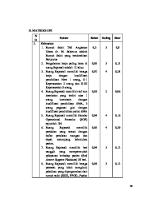
2.1 The staff must comprehend all the electrical schematic diagram and commissioning materials before on site commissioning. 2.2 Keep the site (the machine room, shaft, pit, cabin, car top, landing doors, etc.) clean and tidy. 2.3 After finishing the connection of wirings, it must be double checked, especially the main power input, safety circuit, car door locks, landing door lock circuit, limit switches, terminal switches, also the encoder connection.All the connections must be firm. 2.4 Mechanical and electrical equipment preparations are good enough for operation. 2.5 Reviewing whether the ground wire of three-phase five-wire system connects to the control cabinet on the grounded copper bar, and the ground resistance is ≤4Ω. 2.6 Electrical and mechanical parts of the monomer already had the necessary inspection, testing and commissioning. 2.7 Cabin along the entire shaft without obstruction, collision, and the safety distance shall comply with the relevant provisions. 2.8 The staff should be careful and strict to finish the commissioning work. 2.9 Necessary equipment (under normal condition): Multi-meter Clamp Meter Manipulator Flexible Ruler Common Eelectrical Tools 2.10 The motor self-learning had been done, and in accordance with, all the parameters were entered into the integration system. 2.11 The parameters of door operator according to were all entered into the door operator. Ⅲ、System description and manipulator instruction 3.1 System Description: CTRL71 elevator integrated controller is separated into synchronous machine model and asynchronous machine model,both software and hardware are different, CTRL71 has its own debugging operator on the mainboard, it achieves high voltage into the motherboard, compatible with synchronous machine model and asynchronous machine model. This article mainly introduces the synchronous machine models. When the system controls the synchronous machine, according to the encoder used by the synchronous machine, there are two kinds of PG cards: CTRL71-PG-E and CTRL71-PG-X3. When the CTRL71 system controls the asynchronous machine, the encoder used is ctrl71-pg-b3. Since pg-e is most commonly used and is in plug-in form, its interface is described below. Pins of encoder (Heidenhain ERN1387) side
Fig 1 CTRL71(71A) 设计 Design
图名 Title
CTRL71(71A)调试手册
Sign
Amount
Update No.
Signature
Date
审核 Check
图号 Code
C80M0033P2
标记
处数
更改文件号
签字
日期
批准 Approve
页码 P/Total
2/51
版本 Ver.
A03
Encoder side interface definition 1a
C-
2a
A-
3a
Sensor 0V
4a
R-
5a
B-
6a
D-
7a
Sensor Up
1b
VCC
2b
D+
3b
B+
4b
R+
5b
0V
6b
A+
7b
C+
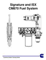
Connect cable of the encoder and the PG card
Fig 2 PG card end terminal
Fig 3 Encord end terminal Connection cable terminal definition PG end
Encord end
1:B-
5a:B-
2:空 3:R+
4b:R+
4:R-
4a:R-
5:A+
6b:A+
6:A-
2a:A-
7:0V
5b:0V
8:B+
3b:B+
9:VCC
1b:VCC CTRL71(71A) 设计 Design
图名 Title
CTRL71(71A)调试手册
Sign
Amount
Update No.
Signature
Date
审核 Check
图号 Code
C80M0033P3
标记
处数
更改文件号
签字
日期
批准 Approve
页码 P/Total
3/51
版本 Ver.
A03
10:C-
1a:C-
11:C+
7b:C+
12:D+
2b:D+
13:D-
6a:D-
14:Null 15:Null
Note: it can be seen from the above that the Heidelberg encoder connection cable of CTRL71 and CTRL80 systems is not universal, the difference lies in the 10th and 11th cable of PG card 3.2 Motherboard functions and operating instructions
Fig 4 Main board appearance and terminal distribution Motherboard terminal function description Tab Code Terminal name Function description CN1 M1 Digital signal input External digital signals are in common emitter mode(0V is common point)/ Common collector mode(+24V is common point) corresponding power input,The common collector mode is reserved for specific project requirements, mainly the common emitter mode, so this connection is (+24V) CTRL71(71A) 设计 Design
图名 Title
CTRL71(71A)调试手册
Sign
Amount
Update No.
Signature
Date
审核 Check
图号 Code
C80M0033P4
标记
处数
更改文件号
签字
日期
批准 Approve
页码 P/Total
4/51
版本 Ver.
A03
CN2 CN3
X1~X16
Digital signal input
X17~X24 A+ B+ ABHC~H1
Digital signal input 5V external independent encoder signal input
X1~X16 are the digital input terminals, the low level is active, and the corresponding functions are defined in the K5 parameters X17~X24 are the digital input terminals, the low level is active Reserved 5V externally encoded signal input for specific project requirements
Drive base blockade lifted AC110 high voltage detection terminal
Must be a passive dry contact switch normally open signal input For safety loop, door lock high voltage detection, specific functions can also be defined in K5 parameters
CN4
X25~X29 XCM
CN5
Y7 Y6/M6 Y5/M5
Relay outputs
The special hardware output point of Y7 is fixed as the brake output, which uses the same common point as Y6. The output point function of Y5 can be defined in K5
CN6
Y4/M4 Y3/M3 Y2/M2 Y1/M1 Y0/M0 24V GND GND CANH4 CAHL4 CANH3 CANL3 CANH2 CANL2 CANH1 CANL1 24V GND CANH6 CAHL6 Null
Relay outputs
Y0~Y4
Mainboard supply input Mainboard 4 way CAN communication
External 24V switching power supply
CAN communication
Used to extend motherboard functions, where 24V and GND are interlinked with CN7
CN10
Reserve
Mainboard main control chip firmware upgrade interface
CN11
Reserve
Main board LCD chip firmware upgrade interface
CN7 CN8
CN9
are relay output, function defined in K5 parameters
Four-way CAN communication, each CAN with a terminal resistance stub cap, CAN1 for HOP communication, CAN2 for HOP communication, CAN3 for car top communication, CAN4 for duplet group control communication
Motherboard with the operator button operation instructions Button Button function
CTRL71(71A) 设计 Design
图名 Title
CTRL71(71A)调试手册
Sign
Amount
Update No.
Signature
Date
审核 Check
图号 Code
C80M0033P5
标记
处数
更改文件号
签字
日期
批准 Approve
页码 P/Total
5/51
版本 Ver.
A03
ESC
In any state, press ESC to exit the current function group menu number or edit state without saving the relevant operation value
UP
In the function group menu, the group number can be incremented by the UP key, and different menus can be selected for operation. In the specific function group data menu, the UP key can also be used for data input
DN
In the menu of function group, the DN key can be used to decrement the group number and select different dispersion. In the data menu of specific function group, the DN key can also be used for data input.
ENTER
Under the function group menu, press ENTER to ENTER the data menu of the function group.In the data menu under the specific function group, after entering the command and pressing ENTER to save, the MCB operation panel will ENTER the K0 menu display by default.
System menu composition of the keypap 1. LOGO display,power on display system LOGO--- CTRL71 2. Speed monitor to show elevator speed and direction 3. Parameter display, parameter view and modification 4. Paremeter copy,a copy of the parameters used for the system 5. Port display to display IO status of relevant board 6. Curve display, display elevator running curve 7. Lift call state, car call, HOP call, call lift 8. I/O monitoring 9. Usage setting 10. Error help, fault related information description 11. Internal data are reserved for use by the manufacturer Note: please refer to appendix x: description of added functions of CTRL71 operator. In the above menu, the main menu involved in debugging is the parameter display menu, setting parameters and grouping of all items as follows: Parameter Specific Function Setting group parameters K0 K0-00 Control mode 0~7 0:No PG V/f control; 2:No PG vector control 3:With PG vector control; 7:PM with PG vector control K0-01 Stop mode 0~1 1:Direct stop;0:Creep stop traction ratio K0-02 1-1:1; 2-2:1; 3-3:1; 4-4:1; K0-03 Running speed 0.25~ K0-04 K0-04 Rated speed 0.25~5.00 m/s K0-05 Rated load 300~9999KG K0-06 Maximum frequency E1-04~120.00 K0-07 Carrier frequency 1.0KHZ~15KHZ
which contains the Default
7
0 2
K0-04 1.75 1000 50 8
CTRL71(71A) 设计 Design
图名 Title
CTRL71(71A)调试手册
Sign
Amount
Update No.
Signature
Date
审核 Check
图号 Code
C80M0033P6
标记
处数
更改文件号
签字
日期
批准 Approve
页码 P/Total
6/51
版本 Ver.
A03
K1
K1-00
Pulse setting
K1-01
Rated power
Select traction machine/speed governor for pulse signal (0~2 ) 0:traction machine; 1:Speed governor; 2:absolute value encoder 0~1 0:A pulse ahead;1:B pulse ahead; 0~650KW
K1-02
Rated voltage
0~510V
K1-03
Rated current
K1-04
Motor poles Rated frequency
Minimum value: 10% of the rated current of the inverter Maximum value: 200% of the rated current of the inverter Number of poles:2~120 Frequency:0.0~200.0 HZ
K1-05
Rmp
0~3000
K1-06 K1-07
Initial Angle Moving direction
K1-08
Motor self-learning select Floor learning
K1-09
Encoder pulse number
-180~+180.0 Moving direction:0~1,0-the same,1-negation Motor self-learning:0~15 0:no-operation; 1:PM stop self-learning; 3:Primary magnetic detection; 4 : Stop type origin self learning; 10: Rotational origin self-learning; 11 : Rotary type induction voltage learning; Floor learning:0~4; 0:no-operation; 1:Floor learning 1-- F4-03/04 floor pulses were not cleared 2:Floor learning 2-- F4-03/04 floor pulses were cleared 3:Speed self-learning; 4 : Adjustment of leveling deviation; 1 ~ 15000ppr
0 0
According to the motor nameplate Settings According to the motor nameplate Settings According to the motor nameplate Settings According to the motor nameplate Settings r According to the motor nameplate Settings
13 : self-learning 1+3+4; 15 : Self-learning occurs when the elevator is operating in opposition to reality
2048
CTRL71(71A) 设计 Design
图名 Title
CTRL71(71A)调试手册
Sign
Amount
Update No.
Signature
Date
审核 Check
图号 Code
C80M0033P7
标记
处数
更改文件号
签字
日期
批准 Approve
页码 P/Total
7/51
版本 Ver.
A03
K2-09
0 ~ 10.0S(Less than 0.5s, the 2 detection function is invalid) After motor Minimum value:0.000Ω self-learning Maximum value:65.000 Ω will get Rated slip (asynchronous 0.00~20.00 HZ After motor machine) self-learning 00.00 HZ will get Leakage reactance Minimum value:0.0% After motor (asynchronous machine) self-learning Maximum value:40.0% 00.0 % will get After motor No-load current Minimum value:0A self-learning (asynchronous machine) Maximum value: will get motor inductance Minimum value:0.00mH After motor self-learning Maximum value:600.00mH will get motor stator After motor 0.000~65.000Ω self-learning will get r Induced voltage system Electrical Angle:0.0~6500.0 After motor mechanical angle:0.0~6500.0 self-learning will get Low speed ring proportional gain:0.00~300.00 15 integral time:0.000~10.000 0.3 0.0%~100.0% 2 switching frequency High speed ring proportional gain:0.00~300.00 10 integral time:0.000~10.000 0.3 Stop speed ring proportional gain:0.00~300.00 Get the value of frequency integral time:0.000~10.000 inverter electric current loop 1000rad/s proportional gain:0~2000rad/s 10.0ms integral time:0.0~100.0ms Torque ceiling electric Forward electric:0%~300% Forward : 200% Backward electric:0%~300% Backward : 200% Torque upper limit Forward regeneration:0%~300% Forward : regeneration Backward regeneration : 200 % Backward : 0%~300% 200 % Zero servo gain 0.00 Gain:0~100.00 0.00 responsiveness:-30.00~30.00 Zero servo speed loop proportional gain:0.000~300.00 Get the value of frequency integral time:0.000~10.000s inverter Stop zero servo gain 0~100 5
K2-10
time to peak torque
K1-10
Encoder wire break detection time 00.0 s nterline resistance (asynchronous machine)
K1-11 K1-12
K1-13 K1-14 K1-15
K1-16
K1-17
K2
K2-00 K2-01 K2-02 K2-03 K2-04 K2-05
K2-06
K2-07 K2-08
accelerate:0~0.50s decelerate:0~1.00s
accelerate : 0.500s decelerate : 0.100s
CTRL71(71A) 设计 Design
图名 Title
CTRL71(71A)调试手册
Sign
Amount
Update No.
Signature
Date
审核 Check
图号 Code
C80M0033P8
标记
处数
更改文件号
签字
日期
批准 Approve
页码 P/Total
8/51
版本 Ver.
A03
K3
K2-11
Torque testing
K2-12
Slide detection
K2-13 K3-00
UCMP detection Starting speed speed: holding time:
K3-01 K3-02
K3-06 K3-07
Accelerated speed Accelerate arc Starting time: End time: Deceleration Decelerate arc Starting time: End time: : Zero velocity threshold 000 mm/s special decaleration Creep distance
K3-08
Releveling function
K3-09 K3-10
Inspection speed low speed force reduction limit switch
K3-11
high speed force reduction limit switch
K3-12
Retention (use of high-speed elevators
K3-13
Retention (use of high-speed elevators
K3-14
Retention (use of high-speed elevators
K3-15
Brake delay time
K3-03 K3-04
K3-05
time of duration:1~10s Size of the amplitude:50~200% pulse:20~100 distance:0~1000mm on/off speed : 0.0%~100.0% (Ddata[73]) time : 0.0~10.0 s (Ddata[74]) 0.2~1.5 /1000 start:0.1s~10.0s /100 end:0.1s~10.0s
3.0 100% pulse:20 distance:40 off 0% 0.0 s
0.700 1.50
0.2~1.5 /1000 start:0.1s~10.0s /100 end:0.1s~10.0s
0.700 1.50
0~100mm/s
50
0.2~1.5 0000 mm,
/1000
speed:20~80 mm/s up:0~50mm down:0~50mm
0.1~0.63m/s /1000 Set value:0~9999 mm/s Monitor value:0~9999mm/s The set value shall be larger than the monitoring value, and the set value of k3-10 shall be larger than the set value of k3-11 Set value:0~9999 mm/s Monitor value:0~9999mm/s The set value shall be larger than the monitoring value, and the set value of k3-11 shall be smaller than the set value of k3-10 Set value:0~9999 mm/s Monitor value:0~9999mm/s Set value:0~9999 mm/s Monitor value:0~9999mm/s Set value:0~9999 mm/s Monitor value:0~9999mm/s open:0~10.00s off:0~10.00s
0.900 Self-learning get the value, only valid when k0-01 =1 speed:30 mm/s up:20 mm down:20 mm 300 1500 0
1800 0
open:0.2s off:0.2s
CTRL71(71A) 设计 Design
图名 Title
CTRL71(71A)调试手册
Sign
Amount
Update No.
Signature
Date
审核 Check
图号 Code
C80M0033P9
标记
处数
更改文件号
签字
日期
批准 Approve
页码 P/Total
9/51
版本 Ver.
A03
K3
K4
K3-16
Zero speed output time
K3-17
The direction of time delay
K3-18 K3-19
creeping speed Rescue speed
K3-20 K3-21 K4-00 K4-01
Emergency electric running speed Floor self-learning speed Leveling sensor delay Leveling adjustment
K4-02
Current positon
K4-03
K4-05
Upward floor-by-floor deviation Downlink floor-by-floor deviation Leveling plate
K4-06
Maximum pulse deviation
K4-07
Floor pulse
K4-08 K4-09 K5-00
Floor display Character set The driver, automatic conversion time Mainboard input selection 1
K4-04
K5
K5-01
K5-02
Mainboard input selection 2
K5-03
Mainboard input selection 3
K5-04
Mainboard output selection
K5-05
Car top board input selection 1
K5-06
Car top board input selection 2
K5-07
Car top selection 1
board
output
start:0~10.00s stop:0~10.00s normal:0.0~1.0 inspection:0.0~2.0
start:1.2s stop:0.6s normal:0.5s inspection : 0.9s 0.300 aceleration : 0.300 speed:0.050 0.300
0.08~K3-09 /1000 aceleration:0.3~1.3m/s2 /1000 speed:0.02~ K3-09 0.1~0.3m/s /1000 0.1~0.63m/s /1000 10~50ms up:-100~+100 mm down:-100~+100 mm floor: pulse: floor:02~top floor deviation:-100~+100 mm floor:01~top-1 floor deviation:-100~+100 mm length:000~999 pulse:0000~9999 floor: Deviation of the pulse: floor: pulse: floor: display: floor: display: 3-200s X01~X12 See "ⅩInput and output for details. X13~X24 See "Ⅹ Input and output for details. X25~X29 See "Ⅹ Input and output for details. Y1:~Y7 See "Ⅹ Input and output for details. A00~A13 See "Ⅹ Input and output for details. A14~A20 See "Ⅹ Input and output for details. B01~B13 See "Ⅹ Input and output for details.
0.300 14 95 95
points"
points"
points"
points"
points"
points"
points"
CTRL71(71A) 设计 Design
图名 Title
CTRL71(71A)调试手册
Sign
Amount
Update No.
Signature
Date
审核 Check
图号 Code
C80M0033P10
标记
处数
更改文件号
签字
日期
批准 Approve
页码 P/Total
10/51
版本 Ver.
A03
K5-08
K5
K6
Car top selection 2
board
output
K5-09
COP board input selection1 X01~X12 Settings and monitoring, the background will be lit when the input point is valid
K5-10
COP board input selection 2 X13~X19 Settings and monitoring, the background will be lit when the input point is valid
K5-11
COP output selection Settings and monitoring, the background will be lit when the input point is valid
K6-00
Lift floor
K6-01
Base station
K6-02
Fire base station
K6-03 K6-04 K6-05 K6-06 K6-07 K6-08 K6-09 K6-10 K6-11
HOP service floor COP service floor Group control Lift address VIP floor Security floor Down collective 1 Down collective 2 Separate time service1
K6-12
Separate time service 1 floor
B14~B17 See "Ⅹ Input and output for details. X01:01 X02:02 03 X04:04 X05:00 00 X07:07 X08:00 09 X10:10 X11:11 12
points"
X03: 00:invalid; 01:ATT; X06: 02:bypass; 03:fireman; X09: 04: independent; X12: 05:spare 06:spare; 07:fire reset; 08 : spare ; X13:13 X14:14 X15: 09:Buzzer off 15 signal; X16:00 X17:00 X18: 10 : Driver oriented 00 upward X19:00 ; 11:door stop; 12:light off; 13:fan off; 14 : VIP function 15 : Driver oriented downward; Q1~Q8, 00:invalid; Q6:06 01~05:spare Q7:07 The rest of the set 0 06:IC card; 07:overload; Top floor: Lowest floor: Parking base: Lock base: First base: Second base: Set by bit:1F~64F Set by bit:1F~64F on/off off 1~128 1~top floor time:00:00~00:00 time:00:00~00:00 S-start time,E-end time,W-week time:00:00~23:59 week:Set by bit from Monday to Sunday Set by bit:1F~64F
CTRL71(71A) 设计 Design
图名 Title
CTRL71(71A)调试手册
Sign
Amount
Update No.
Signature
Date
审核 Check
图号 Code
C80M0033P11
标记
处数
更改文件号
签字
日期
批准 Approve
页码 P/Total
11/51
版本 Ver.
A03
K6
K6-13
Separate time service 2
K6-14 K6-15
Separate time service 2 floor Duplet control peak1
K6-16
Duplet control peak 2
K6-17 K6-18
Time lock Program selection 1
S-start time,E-end time,W-week time:00:00~23:59 week:Set by bit from Monday to Sunday Set by bit:1F~64F time:00:00~23:59 floor:01~top floor time:00:00~23:59 floor:01~top floor time:00:00~23:59 bit0:disperse waiting; bit1:Cancel back end station check; bit2:Reverse cancellation; bit3:Internal call was deleted by mistake; bit4 : Removal of adhesion of HOP; bit5 : Cancel the function of arrival gone at night; bit6 : First power back station check; bit7:Lock the lift to the nearest stop; bit8:Disability function selection; bit9:Software limit function; bit10:time lock; bit11:releveling function; bit12:pre-open function; bit13:speed monitoring function; bit14:VIP function; bit15 : Separate time service function;
1 、 disperse waiting function only work in duplex control mode; 2、Cancel the function of arrival gone at night time: 22:00—7:00; 3、set by bit
CTRL71(71A) 设计 Design
图名 Title
CTRL71(71A)调试手册
Sign
Amount
Update No.
Signature
Date
审核 Check
图号 Code
C80M0033P12
标记
处数
更改文件号
签字
日期
批准 Approve
页码 P/Total
12/51
版本 Ver.
A03
K6-19
Program selection 2
K6-20
Program selection 3
K6-21
Attandent function selection
bit0:Automatic reset (stop) for brake failure bit1:Automatic reset of adhesive contact; bit2 : car top inspection signal input; bit3 : Night security floor function; bit4:down select peak service; bit5 : duplex control peak function; bit6 : Ultra short floor nonstandard; bit7:Ultra short floor up slow down switch not reset; bit8:Ultra short floor down slow down switch not reset; bit9:0,brake does not release detection , 1 , don’t have this function bit10:1, High speed slow down switch sharing one bit11: Single lift mode (generator) bit12: detection of the door is opened bit13: HOP landing light bit14:Landing light blink bit15:Lower level opens if door not in place bit0: cannot run in normal mode when door zone error with UCMP function bit1: open the upper and lower levels inspection with pre-open function bit2:china fire bit2~bit15:spare; bit0:Enter the driver cancel; bit1 : Not responding to HOP calls; bit2:Automatic driver switching; bit3:Inching close; bit4:Automatic close; bit5:beeped intermittently; bit6~bit15:spare;
1.Set by bit;
1.Set by bit
1.When this function code is valid, the f5-00 driver's automatic conversion time is valid; 2、The driver beeped intermittently for 2.5s;
CTRL71(71A) 设计 Design
图名 Title
CTRL71(71A)调试手册
Sign
Amount
Update No.
Signature
Date
审核 Check
图号 Code
C80M0033P13
标记
处数
更改文件号
签字
日期
批准 Approve
页码 P/Total
13/51
版本 Ver.
A03
K6
K7
K6-22
Fire function selection
K6-23
Rescue function selection
K6-24
VIP function selection
K6-25
Flash lead time
K6-26
anti-nuisance function select:0 number:0
K7-00 K7-01 K7-02 K7-03
Internal call registration up call registration down call registration Hot test
K7-04
HOP enabled
bit0:Fire manual reset; bit1:Fire exit; bit2:Arrive gone output ; bit3 : Multiple inside - select instruction registers; bit4:Resume Function; bit5 : Keep the close button closed; bit6:Internal call to register and close; bit7:HOP can display; bit8:Fireman force operation; bit9:Fireman station exit; bit10:Fireman reverse door does not clear inside select command; bit11:Keep the door open button open the door; bit12 : Fire station opens automatically; bit13~bit15:spare; bit0~bit1:Direction Method ( 00 : Automatic calculation direction;01:follower load;10: NXL) bit2 : Stop at the lock base station; bit3 : Emergency running time protection; bit4:Rescue exit mode(0:Door fully opened and exit;1:Close the door and exit); bit5 : overload buzzer output (intermittent); bit6~15:spare; bit0:VIP HOP start(VIP floor) ; bit1:VIP HOP terminal start; bit8:VIPInternal call limit; 0.0~15.0 s 0~4 0 :anti-nuisance function select:4 invalid;1:Weighing judgment; number:3 2:light curtain judgment;3: spare;4:light load judgment; 0~9 Set by bit:1F~64F Set by bit:1F~64F Set by bit:1F~64F Times:0~60000 interval:0~1000 s 0 0~1, 0:permit;1:forbid
CTRL71(71A) 设计 Design
图名 Title
CTRL71(71A)调试手册
Sign
Amount
Update No.
Signature
Date
审核 Check
图号 Code
C80M0033P14
标记
处数
更改文件号
签字
日期
批准 Approve
页码 P/Total
14/51
版本 Ver.
A03
K7-05 K7-06
Door enabled Overload enabled
K7-07
Limit enabled
K7-08
Test function selection
K7
K7-09
Torque test of brake force
K8
K8-00
Weighing channel selection
0~1, 0:permit;1:forbid 0~1, 0:permit;1:forbid Note: only run once, after one automatic recovery is allowed; 0~1, 0:permit;1:forbid Note: only run once, after one automatic recovery is allowed; 0:invalid; 1:UCMP function test; 2:Skidding test function test; 3:hot test mode:off/automatic/manual time:1440 min
0:car top board digtal input; 1:mainboard analog input; 2:mainboard digtal input; 3:car top board analog input; Weighing self - learning 0~100% Settings Pretorque selection 14: Torque compensation; 1F:Through mode(Pretorque automatic compensation function ) Pretorque compensation No load:-100%~100% value Full load:-100%~100% Current load in car 0%~100% Load setting in the car 1 Light load:1%~20% Half load:30%~70% Only valid when 1 and 3 are selected from k8-0 Load setting in the car 2 Full load:90%~100% Over load:102~110% Only valid when 1 and 3 are selected from k8-0 Floor load 1 1F:000/000 2F:000/000 3F:000/000 4F:000/000 …… 7F:000/000 8F:000/000
K8-01 K8-02
K8-03 K8-04 K8-05
K8-06
K8-07
K8-08~ K8-21
Floor load 2~15
9F:000/000 11F:000/000 …… 15F:000/000
10F:000/000 12F:000/000 16F:000/000
0 0
0
0
automatic time : 1440 min 3
0% 1F
-50% +50% 0% Light load : 10% half load : 50% Full load : 95% Over load : 102% 000/000 Sampling value, self learning acquisition No load/full load 000/000 Sampling value, self learning acquisition No load/full load
CTRL71(71A) 设计 Design
图名 Title
CTRL71(71A)调试手册
Sign
Amount
Update No.
Signature
Date
审核 Check
图号 Code
C80M0033P15
标记
处数
更改文件号
签字
日期
批准 Approve
页码 P/Total
15/51
版本 Ver.
A03
K9-05
…… 127F:000/000 128F:000/000 Idle return to base station 0~240min (s) time Car energy saving time light:0~240min fan:0~240min Current time date:2018/06/28 time:00:00:00 Maintenance days set 0~99 Time Settings for 0~10min (s) decentralized services relevel stop delay 0.0~5.0s
K9-06
Arrival gone output delay
KA
KA-00 KA-01 KA-02
KA
KA-03
KA-05
Cumulative running hour runing time Software version 1 mainboard operator Software version 2 car top board COP board Software version 3 inverter Speed command
KA-06
Feedback speed
KA-07 KA-08 KA-09
Busbar voltage Output current Output frequency
KA-10 KA-11
Torque current Output voltage
KA-12 KA-13 KA-14
Output torque Output power communication jamming 1
KA-15
communication jamming 2
KA-16
Expand board input state
K9
000/000
Floor load 16
K8-22
K9-00 K9-01 K9-02 K9-03 K9-04
KA-04
3 3 3
0 3 0.0
0~1000ms 1.When the set value is greater than 10ms, the elevator display is switched to the destination floor and the time set by fb-07 is delayed to output the arrival gong; 2、When the set value is < 10ms, the elevator stops and outputs the arrival gong; 0~99999 0~99999999 mainboard:000.00 operator:000.00
0
0 0
car top board:000.00 COP board:000.00
FLASH ID:00 ROM ID:00 Monitoring value,Display set speed Monitoring value , Direct display speed, mainboard need to convert to speed Monitoring value Monitoring value Monitoring value 0.00~99.99 00.00 A Monitoring value 00.00 V Monitoring value,0%~100% Monitoring value,99.99 CAN1:0~9 CAN2:0~9 9-highest , CAN3:0~9 CAN4:0~9 0-interupt SPI :0~9 9-highest , 0-interupt Monitoring value:A20~A43
CTRL71(71A) 设计 Design
图名 Title
CTRL71(71A)调试手册
Sign
Amount
Update No.
Signature
Date
审核 Check
图号 Code
C80M0033P16
标记
处数
更改文件号
签字
日期
批准 Approve
页码 P/Total
16/51
版本 Ver.
A03
KA-17 KA-18 KB
KB-00 KB-01 KB-02 KB-03 KB-04 KB-05
KB-06 KB-07 KB-08 KB-09 KB-10 KB-11
Expand board Monitoring value:B10~B22 output state HOP communication state Monitoring value : 1F~64F , 1 display by bit Door machine 1~2 quatity Door operator 1 Set by bit:1F~64F service floor Door operator 2 Set by bit:1F~64F service floor Door protection 5~99 time Times of failure 0~20 opening and closing Operating base 0:close normally;1:waiting at station door state the base floor with door opening; 2: waiting at every floor with door opening Door holding time 1~1000s base floor door open hold time Closing delay time Special door hold Forced closing time Open mode
KB
KB-12
Door control selection 0000000000000000
KC
KC-00
inverter overheats
1~1000s 10~1000s 10~1000s 5~180s 00:Front and back control simultaneously; 01:External call independence, internal call independence; 02:External call independent, internal call at the same time; 03:External call independent, internal call manual; bit0:Non - door zone can open during maintenance; bit1:Open door in position to hold open output; bit2:Manual control through door opens only one door; bit3:Continue to close the door after the door is fully closed; bit4:spare; bit5~bit15:spare; Temperature:50~150 Action Selection:0- Slowing down to stop;1- Free running stop;2- emergency stop;3-keep running;
0~3 1
12 12
5 3 10 180 30 120 00
3
CTRL71(71A) 设计 Design
图名 Title
CTRL71(71A)调试手册
Sign
Amount
Update No.
Signature
Date
审核 Check
图号 Code
C80M0033P17
标记
处数
更改文件号
签字
日期
批准 Approve
页码 P/Total
17/51
版本 Ver.
A03
KC-01
Input missing detection
KC-02
Output missing phase detection
KC-03
motor overload protection Main circuit undervoltage
KC-04
KD KF
KF
phase
KC-05
Overspeed detection
KC-06
speed variation
KC-07
PG Break line detection
KC-08
Overacceleration detection
KC-09 KD-00 KD-01 KF-00 KF-01
Run time protection Baud rate setting Monitoring adddress Password 1 mainboard parameters update initialize:0000 fault:0
KF-05
Inverter parameter update initialize:0000 fault:0
KF-06
Language setting Mainboard:english inverter:chinese
enabled:0-invalid;1-always detect;2-detect when running; 3- Only detect at a certain speed voltage:0.0%~50.0% 0:no detect 1:Detect one phase output missing phase 2:Detect the missing phase of the output above two phases 0.0~5.0 min
200V grade:150V~210V 400V grade:300V~420V 0%~120% 0.0~2.0 0%~50% 0.0~10.0 s 0:no detect,1:detect 0.0~10.0 s 0:Detect when the power is on 1:Detect only when entering run instructions 0.0%~20.0% 0~99s 0:20K-1; 0~256 0000 initialize:0-Null; 2220- Factory parameter initialization; 3330- Data initialization with the exception of shaft parameters and weighing parameters; Fault :0-invalid;1-reset UCMP fault,2-reset all fualt,3- Clear fault record initialize:0-Null; 1110- User parameter values are initialized; 2220- Factory parameter initialization; 5550-oPE04 fault reset; fault :0-invalid;1- Clear the contents of the inverter U2/U3 chinese/english
1
0
1.0
115% 0.0 10% 0.5s 1 2.0 0 1.5 45 0 1 0000
english
CTRL71(71A) 设计 Design
图名 Title
CTRL71(71A)调试手册
Sign
Amount
Update No.
Signature
Date
审核 Check
图号 Code
C80M0033P18
标记
处数
更改文件号
签字
日期
批准 Approve
页码 P/Total
18/51
版本 Ver.
A03
KF-07
inverter replication function select:0 setting:0 Mainboard replication select:0 setting:0
select:0~1,0-invalid;1-valid; 0 setting:0~3,0-invalid;1-read; 0 2-copy;3-verify;
select:0~1,0-invalid;1-valid; 0 setting:0~3,0-invalid;1-read; 0 2-copy;3-verify; Read: write the inverter parameters to the operator Copy: write the operator parameters to the inverter verify:compare operator and converter parameters E E1-A (01) E1-A Fault analysis Fault analysis F:00 S:V* T:month/day/hour/minute Inverter monitoring BV-busbar voltage(U2-08) ; OV:output voltage(U2-07); I:output current(U2-05); S:output speed(U2-04); Mainboard monitoring 1 S:given speed SPI:SPI communication quanlity,0~9, 9-highest,0-interupt W: Weight data percentage CTB : car top board communication quanlity Mainboard monitoring 2 Change from 0 to 1 when input and output are valid input:X0~X24 output:Y0~Y7 Car top board monitoring Change from 0 to 1 when input and output are valid Input:A0~A7、A10~A17、A20 output:B0~B7、B10~B17 COP board monitoring Change from 0 to 1 when input and output are valid input:X0~X24 output:Y0~Y7 First two failures …… The first 50 failures KF-08
Ⅳ、Commissioning flow chat
CTRL71(71A) 设计 Design
图名 Title
CTRL71(71A)调试手册
Sign
Amount
Update No.
Signature
Date
审核 Check
图号 Code
C80M0033P19
标记
处数
更改文件号
签字
日期
批准 Approve
页码 P/Total
19/51
版本 Ver.
A03
Start
Pre-torque function commissioning
Check the external circuit
Basic parameters setting
Running comfort adjustment
Shaft SW signal check、 Slow speed run
Motor Tuning
Other function test
Parameters recording
Floor self-learning
End Commissioning flow chat Ⅴ、Peripheral line inspection 5.1 Turn on the main power,measure the voltage among R, S, T, it must satisfy as below: R-S
AC380V±7%
S-T
AC380V±7%
R-T
AC380V±7%
5.2 Check the Phase sequence relay in working normal or not . if the alarm indicator is ON, please check the3 phase AC power supply is failure or wrong . 5.3 Check if the lift is in Inspection Mode; 5.4 Check all safety switches, safety circuit in the normal state,Mainboard high voltage test point X25 lights up. The safety circuit switches are: Code
Name
Respective positions
AY
E.stop switch next to the motor
AD1
1 Floor E.stop switch
Shaft inspection and lighting device
AD
Pit stop switch
Pit inspection and lighting device
KXZ
Governor rope off switch
Pit
ZK
COP E.stop switch
COP
AT
Car top E.stop switch
Car top maintenance lighting device
SDK
Car top lock switch
Car top
st
Note
Beside the motor
Only for machine roomless elevator
Only for machine roomless elevator
Continued table Code
Name
Respective positions
KTJ
Trap door Switch
Car top
Note Only for machine roomless elevator
CTRL71(71A) 设计 Design
图名 Title
CTRL71(71A)调试手册
Sign
Amount
Update No.
Signature
Date
审核 Check
图号 Code
C80M0033P20
标记
处数
更改文件号
签字
日期
批准 Approve
页码 P/Total
20/51
版本 Ver.
A03
KXJ
Safety gear switch
Car bottom (small room) / car top (roomless)
YH、YH1、YH2
Buffer Switch
pit
SK4、XK4
Up and down limit switch
shaft
VK
Governor switch
Governor
KYD
Traction rope anti-off switch
Rope head
AKT
Stop switch control cabinet
Control cabinet
XJJ
Phase sequence relay
Control cabinet
PCK
Hand wheel switch
Motor (only for elevator with room)
Only for 2:1 rope ratio
5.5 Check the car door locks and all the landing door locks, in the normal state, Mainboard high voltage monitoring point X26,X27(back door X28) light up,And one by one manual action, make the mainboard high pressure monitoring point X26,X27(back door X28) off. 5.6 The default function definition of mainboard input points is as follows. Confirm whether the input point definition corresponds to the following table according to the field needs. Input
Instruction of input
Code of
Subordinate
point
point
input point
position
X1
leveling sensor
GD
car top
X2
UCMP door zone
X3
Control
feedback detection
cabinet
Bypass feedback
X5
Earthquake detection
X7 X8 X9
cabinet
Closed door output
X4
X6
Control
Control cabinet MR
Detection of MC1 and
MC1
brake contactor Detection of Brake
JBZ
contactor
Control cabinet Control cabinet
ARD signal
MR
Inspection / normal
Control
signal
cabinet Control
Correspondin g function code
parameter
note
s
K5-01
00
NO
K5-01
00
NO
K5-01
00
NO
K5-01
00
NO
K5-01
00
NO
K5-01
00
NC
K5-01
00
NO
K5-01
00
NO
K5-01
00
NC
K5-01
00
NO
K5-01
00
NO
X10
Slow up
MS
X11
Slow down
MX
X12
Up Limit switch
SK3(118)
Shaft
K5-01
00
NC
X13
Down Limit switch
XK3(120)
Shaft
K5-02
00
NC
cabinet Control cabinet
CTRL71(71A) 设计 Design
图名 Title
CTRL71(71A)调试手册
Sign
Amount
Update No.
Signature
Date
审核 Check
图号 Code
C80M0033P21
标记
处数
更改文件号
签字
日期
批准 Approve
页码 P/Total
21/51
版本 Ver.
A03
X14 X15 X16
Up first slow down
SK1
swicth Down first slow down
XK1
swicth Second slow down
XSK2
swicth
Shaft / car top Shaft / car top Shaft / car top Control
K5-02
00
NC
K5-02
00
NC
K5-02
00
NC
X17
Door bypass signal
X18
Fire signal 1
KCF
X19
Left brake switch
BK1
X20
Right brake switch
BK2
X21
Star seal feedback
JFX
X22
Fire signal 2
KCF
MR or SCR
K5-02
NO
X23
Fire man
KXY
Fire base
K5-02
NO
X24
Lock signal
YK
Lock base
K5-02
cabinet SCR or MR Traction motor Traction motor Control cabinet
K5-02 K5-02
00
NO
K5-02
00
NC
K5-02
00
NC
K5-02
00
NO
NO 00
Safety signal high X25
NC
voltage detection
03
Mainboard
K5-03
point Car door signal high X26
00
voltage detection
24
Mainboard
K5-03
point Landing door signal X27
00
high voltage detection
22
Mainboard
22A
Mainboard
K5-03
point Back door signal high X28
voltage detection point
X29
Spare
Code 00 01 02 03 04 05
Mainboard input terminal function definition code table Input point description Code Input point description Unused; Up leveling sensor normally 33 Up leveling sensor normally open input; close input; Down leveling sensor normally 34 Down leveling sensor normally open input; close input; Door zone NO input; 35 Door zone NC input; Safety circuit feedback NO input; Door lock circuit feedback NO input;
36
Safety circuit feedback NC input;
37
Door lock circuit feedback NC input;
CTRL71(71A) 设计 Design
图名 Title
CTRL71(71A)调试手册
Sign
Amount
Update No.
Signature
Date
审核 Check
图号 Code
C80M0033P22
标记
处数
更改文件号
签字
日期
批准 Approve
页码 P/Total
22/51
版本 Ver.
A03
06
Running output feedback NO input; Brake output feedback NO input; Inspection signal NO input;
38
41
12
Inspection upward signal NO input; Inspection downward signal NO input; Fire protection signal NO input; Up limit signal NO input;
13
07 08 09
39 40
Running output feedback NC input; Brake output feedback NC input; Inspection signal NC input;
43
Inspection upward signal NC input; Inspection downward NC input; Fire protection NC input;
44
Up limit signal NC input;
Down limit signal NO input;
45
Down limit signal NC input;
14
Overload NO input;
46
Overlaod NC input;
15
Full load NO input;
47
Full load NC input;
16
Up slow down 1 NO input;
48
Up slow down 1 NC input;
17
Down slow down1 NO input;
49
Down slow down1 NC input;
18
Up slow down 2 NO input;
50
Up slow down2 NC input;
19
Down slow down 2 NO input;
51
Down slow down2 NC input;
20
Up slow down 3 NO input;
52
Up slow down3 NC input;
21
Down slow down3 NO input;
53
Down slow down3 NC input;
22
Door seal output feedback NO input; Fireman SW NO input;
54
Door seal output feedback NC input; Fireman SW NC input;
56
28
Door operator1 light curtain input; Door operator2 light curtain NO input; Brake output feedback1NO input; Power failure emergency operatio NO input; Elevator lock signal NO input;
60
Door operator1 light curtain NC input; Door operator2 light curtain NC input; Brake output feedback 1 NC input; Power failure emergency operatio NC input; Elevator lock signal NC input;
29
Safety signal NO input2;
61
Safety signal NC input2;
30
62
Synchronous motor star-seal feedback NC input Door lock citcuit2 feedback NC input; Door operator1 safey gear NC;
67
Synchronous motor star-seal feedback NO input; door lock circuit 1 feedback NO input; Door operator safety gear 1 NO; Door operator safety gear 2 NO; Motor overheat NO;
99
Door operator2 safety gear NC; Motor overheat NC;
68
Earthquake signal NO;
100
Earthquake signal NC;
69
Rear door forbidden NO;
101
Rear door forbidden NC;
70
Light load NO;
102
Light load NC;
71
Half load NO;
103
Half load NC;
72
Fire base floor switchover NO;
104
Fire base floor switchover NC
10 11
23 24 25 26 27
31 65 66
42
55
57 58 59
63 97 98
CTRL71(71A) 设计 Design
图名 Title
CTRL71(71A)调试手册
Sign
Amount
Update No.
Signature
Date
审核 Check
图号 Code
C80M0033P23
标记
处数
更改文件号
签字
日期
批准 Approve
页码 P/Total
23/51
版本 Ver.
A03
73
False floor NO input
105
False floor NC input
74
Water level NO input
106
Water level NC inputt
75
spare
76
Door 1 open NO input
108
Door 1 open NC input
77
Door 2 open NO input
109
Door 2 open NC input
78
Brake output feedback2NO input; External fault NO input
110
Brake output feedback 2 NC input; External fault NC input
112
83
Terminal station verifies NO input Door 1 short connection detects NO input Door 2 short connection detects NO input HOMING NO input
115
Terminal station verifies NC input Door 1 short connection detects NC input Door 2 short connection detects NC input HOMING NC input
84
Emergency run NO input
116
Emergency run NC input
85
Main switch disconnects NO input Door lock bypass NO input
117
Main switch disconnects NC input Door lock bypass NC input
119
88
Compensated chain extension feedback NO input Clipper feedback NO input
120
Compensated chain extension feedback NC input Clipper feedback NC input
89
Fire signal 2 NO input
121
Fire signal 2 NC input
90
Fire man 2 NO input
122
Fire man 2 NC input
91
Fire reset NO input
123
Fire reset NC input
92
LM SW NO input
124
LM SW NC input
93
UCMP action signal NO input
125
UCMP action signal NC input
94
UCMP door zone NO input
126
UCMP door zone NC input
95
UCMP door lock NO input
127
UCMP door lock NC input
79 80 81 82
86 87
111
113 114
118
161 Second forced deceleration Second forced deceleration switch NC input switch NO input 5.7 The main board output point default function is defined as follows. According to the field needs, confirm whether the 129
output point definition corresponds to the following table output
Instruction of
Code of
Subordinate
point
output point
output point
position
Y1
Monitor panel
Control
failure
cabinet
Y2
energy feedback
Y3
Door sealed output
Y4
Correspondin
Control cabinet Control cabinet
Return to base for
Control
generator
cabinet
g function code
parame
note
ters
K5-04
00
K5-04
00
K5-04
00
K5-04
00
Settings + monitoring Settings + monitoring Settings + monitoring Settings + monitoring
CTRL71(71A) 设计 Design
图名 Title
CTRL71(71A)调试手册
Sign
Amount
Update No.
Signature
Date
审核 Check
图号 Code
C80M0033P24
标记
处数
更改文件号
签字
日期
批准 Approve
页码 P/Total
24/51
版本 Ver.
A03
Y5
MC main contactor MC1 main
Y6
contactor、
cabinet
MC1、
Control
JFX
cabinet
Star-seal contactor Y7
Control
MC
Brake contactor
Control
JBZ
K5-04
00
K5-04
00
K5-04
00
Settings + monitoring Settings + monitoring Settings +
cabinet monitoring Motherboard output terminal function defines code table Code Output point description Code Output point description 0 Unused; 1
running contactor output;
10
error status;
2
brake contactor output;
11
running monitoring;
3
door seal contactor output;
12
14
Synchronous motor star-seal output; Power off emergency running switchover; Integrated controller normal
Door operator1 close;
15
Emergency buzzer output;
7
Door operator2 open;
16
Brake forced output;
8
Door operator2 close;
17
Elevator upward sign;
9
Bake、running contactor normal;
18
Lighting、fans output;
19
Medical sterilizing output;
21
Electrical lock output;
20
Not door area parking;
22
No serving status
23
Rescue run complete output
25
Rope clip reset
5
Fire to base floor signal feedback; Door operator1 open;
6
4
13
Firman lighting Output of Energy returns 30 29 Fire siganl state 5.8 The default input and output functions of the car top board are defined as follows. According to the field needs, confirm whether the input and output point definitions correspond to the following table 27
Alarm filter output
28
Correspondin
Input
Instruction of input
Code of
Subordinate
point
point
input point
position
A00
Front door fully open
2KM
Car top
K5-05
35
NC
A01
Front door fully close
3GM
Car top
K5-05
37
NC
A02
Back door fully open
2KM1
Car top
K5-05
36
NC
A03
Back door fully close
3GM1
Car top
K5-05
NC
K5-05
A05
Car top Car top
38 00
K5-05
00
A06
Car top
A07 A10
KAP1
K5-05 K5-05
00
Car top
KAP2
Car top
K5-05
A04
door safety edge 1 door safety edge 2
g function code
parameter
note
s
NC NC
39 40
CTRL71(71A) 设计 Design
图名 Title
CTRL71(71A)调试手册
Sign
Amount
Update No.
Signature
Date
审核 Check
图号 Code
C80M0033P25
标记
处数
更改文件号
签字
日期
批准 Approve
页码 P/Total
25/51
版本 Ver.
A03
A11
door light curtain 1
KAPA
Car top
A12
door light curtain 2
KAPB
33
Car top
K5-05 K5-05
spare
Car top
K5-05
00
Up releveling
YPS
Car top
K5-06
00
NO
YPX
Car top
K5-06
00
NO
KGT
Car top
K5-06
00
KZT
Car top
K5-06
00
Car top
K5-06
00
A13 A14 A15
Down releveling
A16
Over load
A17
Full load
A20
spare
output
Instruction of output
Code of
Subordinate
point
point
output point
position
Front door open signal
JKM
B00
Front door close
JGM
signal
B01
Front door Slow
MGM
B02
closing signal
B03
spare
B04 B05
Back door open signal
1JKM
Back door close signal
1JGM
Back door Slow
1MGM
Car top Car top Car top
Correspondin g function code K5-07 K5-07 K5-07
34
parameter 00 00 00 00
Car top
K5-07
00
Car top
K5-07
00
Car top
K5-07
00
K5-07
00
Car top
K5-07
00
Car top
K5-07
00
B06 B07 B10
closing signal light
JN1、JN2
B11 B12
fan
FS1、FS2
B13
spare
Car top
K5-07
00
B14
spare
Car top
K5-08
00
B15
Up arrive gong
Car top
K5-08
00
B16
Down arrive gong
Car top
K5-08
00
B17
sound-light alarm
Car top
K5-08
00
Code 00 01 02 03 04 05 06 07 08 09 10 11
DF
note
s
K5-07
Car top
NC NC
Car roof input terminal function definition code table Input point description Code Input point description Unused; 33 Door 1 light curtain NO input; Door 1 light curtain NC input; 34 Door 2 light curtain NO input; Door 2 light curtain NC input;; 35 Door 1 fully open NO input; Door 1 fully open NC input; 36 Door 2 fully open NO input; Door 2 fully open NC input; 37 Door 1 fully close NO input; Door 1 fully close NC input; 38 Door 2 fully close NO input; Door 2 fully close NC input; 39 Door 1 safety edge NO input; Door 1 safety edge NC input; 40 Door 2 safety edge NO input; Door 2 safety edge NC input; 41 Light load NO input; Light load NC input; 42 Half load NO input; Half load NC input; 43 Full load NO input; Full load NC input; CTRL71(71A) 设计 Design
图名 Title
CTRL71(71A)调试手册
Sign
Amount
Update No.
Signature
Date
审核 Check
图号 Code
C80M0033P26
标记
处数
更改文件号
签字
日期
批准 Approve
页码 P/Total
26/51
版本 Ver.
A03
12 13 14 15 16 17 18
Over load NO input; Up Releveling sensor NO input; Down Releveling sensor NO input; Door motor overheat NO input; Car top INS NO input; Car top slow up NO input; Car top slow down NO input;
44 45 46 47 48 49 50
Over load NC input; Up Releveling sensor NC input; Down Releveling sensor NC input; Door motor overheat NC input; Car top INS NC input; Car top slow up NC input; Car top slow down NC input;
Ⅵ、Traction machine(Motor) self-learning method and procedure This step have been finished before leaving the factory, When commissioning, the self-learning can be done again according to the actual situation 6.1 Tuning instruction a) Magnetic pole position identification must be carried out before the first operation of the synchronous motor, otherwise it cannot be used normally and is extremely dangerous; b) For safety, the elevator must motor self-learning under the maintenance state, can choose to stop the engine's self-study or rotary engine's study, from the operating convenience and safety, we suggest to stop type self-learning, rotate engine's self learning, the motor can't hang rope and brake to open. c) During the learning process, there will be a large excitation sound of the synchronous motor, and the process will last for a few minutes. If there is anything wrong with the learning process, it should be stopped immediately. During the whole process, if there is any reported fault, please start the self-learning again. d) When replacing the encoder of the synchronous motor, the self-learning of the motor must be carried out again. When replacing the wiring of the host or the PG card and the drive of the inverter, it is also recommended to re-learn the self-learning of the motor if there is no empirical operation from the perspective of safety; e) During the whole self-learning process, all personnel are prohibited from entering the roof of the car, the car, the well and other behaviors that lead to danger; 6.2 Synchronous motor stop type self - learning operation steps a) Ensure that the UVW power line of the motor is connected to the UVW terminal port of the inverter; b) Set the main board k1-01, k1-02, k1-03, k1-04, k1-05, k1-09 according to the parameters of the motor nameplate and encoder, If there is no pole number or log number (log number is two times of the number of poles) on the nameplate of the host machine, it can be calculated as P = (120*f)/N, where N is the speed of the motor, f is the frequency of the host machine, P is the number of poles of the host machine, and then filled into k1-04; c) Make sure that the encoder of the main engine is connected to PG, and release the holding brake for a short time by manual or electric means to monitor the value of the main board parameter KA-06. When the car goes up, the value should be positive; when the car goes down, the value should be negative, If not, invert the value of the encoder direction of k1-07, and then release the lock brake briefly by manual or electric means to monitor the value of the main board parameter k4-02. When the car goes up, the value should be positive; when the car goes down, the value should be positive or negative. If not, invert the value of the pulse direction of k1-00. d) Record the value of the K1-06, set K1-08 host self-learning parameters to 13, if there is no fault, MC1 contactor will suck, drive motor, excitation sound, after a few minutes, if there is no fault after the success of MC1 contactor will release, motherboard shows tuning is successful, then again see K1-06 values can and previous value if there is a difference, if there is no change, please confirm whether tuning is successful, if K1-08 in the parameters motor self learning, in a no 13 this parameter can choose, you will need to set three 1 and 4 complete motor self-learning; CTRL71(71A) 设计 Design
图名 Title
CTRL71(71A)调试手册
Sign
Amount
Update No.
Signature
Date
审核 Check
图号 Code
C80M0033P27
标记
处数
更改文件号
签字
日期
批准 Approve
页码 P/Total
27/51
版本 Ver.
A03
e) Gently move the elevator in inspection state, observe whether the elevator is running in the opposite direction and whether the main board has reported faults. If the direction is opposite, set the running direction in k1-07 to be reversed, and then conduct self-learning again. If there are no other problems, then observe whether the current size is normal. 6.3 Synchronous motor rotation self - learning operation steps a) Ensure that the UVW power line of the motor is connected to the UVW terminal port of the inverter; b) Set the main board k1-01, k1-02, k1-03, k1-04, k1-05, k1-09 according to the parameters of the motor nameplate and encoder, If there is no pole number or log number (log number is two times of the number of poles) on the nameplate of the host machine, it can be calculated as P = (120*f)/N, where N is the speed of the motor, f is the frequency of the host machine, P is the number of poles of the host machine, and then filled into k1-04; c) Make sure that the encoder of the main engine is connected to PG, and release the holding brake for a short time by manual or electric means to monitor the value of the main board parameter KA-06. When the car goes up, the value should be positive; when the car goes down, the value should be negative, If not, invert the value of the encoder direction of k1-07, and then release the lock brake briefly by manual or electric means to monitor the value of the main board parameter k4-02. When the car goes up, the value should be positive; when the car goes down, the value should be positive or negative. If not, invert the value of the pulse direction of k1-00. d) Elevator traction machine and load (wire) fully release, open the brake according to the principle diagram of the brake circuit, K1-06 value, K1-08 motor self-learning parameter is set to 1, MC1 contactor or absorption, motor start turning, if there is no failure, MC1 contactor is released, then the motor shows tuning is successful, in the same way and then the K1-08 self-learning parameter is set to the motor into 3, self-learning, to complete the second step after the success, then K1-08 motor self-learning parameters set to 10, to complete the third step self learning, then K1-08 motor self-learning parameters set 11,Complete the fourth step of self-learning.Then check whether the value of k1-06 is different from the previous value. If there is no change, please confirm whether the tuning is successful. e) Gently move the elevator in inspection state, observe whether the elevator is running in the opposite direction and whether the main board has reported faults. If the direction is opposite, set the running direction in k1-07 to be reversed, and then conduct self-learning again. If there are no other problems, then observe whether the current size is normal. 6.4 Asynchronous motor stop type self - learning operation steps a)
Ensure that the UVW power line of the motor is connected to the UVW terminal port of the inverter;
b)
Set the main board k1-01, k1-02, k1-03, k1-04, k1-05, k1-09 according to the parameters of the motor nameplate and encoder, If there is no pole number or log number (log number is two times of the number of poles) on the nameplate of the host machine, it can be calculated as P = (120*f)/N, where N is the speed of the motor, f is the frequency of the host machine, P is the number of poles of the host machine, and then filled into k1-04;
c)
Make sure that the encoder of the main engine is connected to PG, and release the holding brake for a short time by manual or electric means to monitor the value of the main board parameter KA-06. When the car goes up, the value should be positive; when the car goes down, the value should be negative, If not, invert the value of the encoder direction of k1-07, and then release the lock brake briefly by manual or electric means to monitor the value of the main board parameter k4-02. When the car goes up, the value should be positive; when the car goes down, the value should be positive or negative. If not, invert the value of the pulse direction of k1-00.
d)
Set the self-learning value of k1-08 to 0. If there is no fault, MC1 contactor will close, drive the motor, and CTRL71(71A) 设计 Design
图名 Title
CTRL71(71A)调试手册
Sign
Amount
Update No.
Signature
Date
审核 Check
图号 Code
C80M0033P28
标记
处数
更改文件号
签字
日期
批准 Approve
页码 P/Total
28/51
版本 Ver.
A03
emit excitation sound; e)
Gently move the elevator in inspection state, observe whether the elevator is running in the opposite direction and whether the main board has reported faults. If the direction is opposite, set the running direction in k1-07 to be reversed, and then conduct self-learning again. If there are no other problems, then observe whether the current size is normal.
6.5 Asynchronous motor rotation self - learning operation steps a)
Ensure that the UVW power line of the motor is connected to the UVW terminal port of the inverter;
b)
Set the main board k1-01, k1-02, k1-03, k1-04, k1-05, k1-09 according to the parameters of the motor nameplate and encoder, If there is no pole number or log number (log number is two times of the number of poles) on the nameplate of the host machine, it can be calculated as P = (120*f)/N, where N is the speed of the motor, f is the frequency of the host machine, P is the number of poles of the host machine, and then filled into k1-04;
c)
Make sure that the encoder of the main engine is connected to PG, and release the holding brake for a short time by manual or electric means to monitor the value of the main board parameter KA-06. When the car goes up, the value should be positive; when the car goes down, the value should be negative, If not, invert the value of the encoder direction of k1-07, and then release the lock brake briefly by manual or electric means to monitor the value of the main board parameter k4-02. When the car goes up, the value should be positive; when the car goes down, the value should be positive or negative. If not, invert the value of the pulse direction of k1-00.
d)
Elevator traction machine and load (wire) fully release, open the brake according to the principle diagram of the brake circuit, K1-06 value, K1-08 motor self-learning parameter is set to 1, MC1 contactor or absorption, motor start turning, if there is no failure, MC1 contactor is released, then the motor shows tuning is successful, in the same way and then the K1-08 self-learning parameter is set to the motor into 3, self-learning, to complete the second step after the success, then K1-08 motor self-learning parameters set to 10, to complete the third step self learning, then K1-08 motor self-learning parameters set 11,Complete the fourth step of self-learning.Then check whether the value of k1-06 is different from the previous value. If there is no change, please confirm whether the tuning is successful.
f) Gently move the elevator in inspection state, observe whether the elevator is running in the opposite direction and whether the main board has reported faults. If the direction is opposite, set the running direction in k1-07 to be reversed, and then conduct self-learning again. If there are no other problems, then observe whether the current size is normal.
Ⅶ、The elevator starts and stops debugging Have a test run after setting parameters as the following table , according to motor power and motor characteristic,it may cause different start effects, the default parameters can be adapted to most machines, so set parameters as the following table and have a test run, observe when the motor starts whether is will roll back and the sound is normal or not. If you meet some abnormal situation then reset those parameters and check if the sound is eliminated.
S/n
Function
Setting
code
value
Definition
Explanation
CTRL71(71A) 设计 Design
图名 Title
CTRL71(71A)调试手册
Sign
Amount
Update No.
Signature
Date
审核 Check
图号 Code
C80M0033P29
标记
处数
更改文件号
签字
日期
批准 Approve
页码 P/Total
29/51
版本 Ver.
A03
1
K2-00
15
Proportional gain
The larger the gain, the smaller the integral, the
0.5
Integral time
faster the response, the start of the reaction, the acceleration of the gain, the reduction of the integral
2
K2-07
0
Zero servo gain
0
Zero servo respond
3
K2-08
10
Zero servo speed loop gain
0.1
Zero servo speed loop integral time
4
K2-09
5
Stop zero servo gain
5
K3-16
0.2
Open brake delay
Ensure the start zero speed delay in k3-16 > 0.4 + k3-15 open
0.2
Close brake delay
lock delay
1.2
Zero speed start time
Ensure the start zero speed delay in k3-16 > 0.4 + k3-15 open
0.6
Zero speed stop time
lock delay
Normal direction
According to field adjustment, the elevator can stop at zero
0.5
delay
speed
0.9
Inspection direction
6
7
K3-15
K3-17
delay
8
9
K8-02 K8-03 No load
Select Start
1F
Compensation
14: Torque compensation; 1F : Through mode ( Pretorque automatic compensation function)
Pretorque compensation value
-50%
7.1 Starting torque compensation debugging with weight compensation
This is suitable for the old elevator using tamochuan encoder, when k8-02 is set to 14; 7.2 Starting torque compensation debugging without weight compensation a) This method applies when using the encoder ERN1387, when k8-02 is set to 1F; b) First adjust the zero-speed start time in k3-16, and the zero-speed start delay in k3-16 is > 0.4 + k3-15, and gradually increase the zero-speed start time in k3-16, until the elevator keeps torque compensation when the brake is opened; c) Observe the status of zero servo during starting, adjust the parameters related to the speed controller ASR, k2-00 to reduce backward slip and vibration; d) Adjust the parameter k2-07 again to remove the back slide when the brake is opened. The starting effect is also affected by the force between the guide boot and the guide rail. If you do not run the car at zero speed, but the starting force is still too strong, please check the force of the guide boot and the guide rail spacing and flatness. a)
Ⅷ 、Switch Installation Specifications 8.1installation requirements of slow down switches The proposed installation: CTRL71(71A) 设计 Design
图名 Title
CTRL71(71A)调试手册
Sign
Amount
Update No.
Signature
Date
审核 Check
图号 Code
C80M0033P30
标记
处数
更改文件号
签字
日期
批准 Approve
页码 P/Total
30/51
版本 Ver.
A03
Speed 0.4m/s 0.5m/s 0.63m/s 1.0m/s 1.5m/s 1.6m/s 1.75m/s 2.0m/s 2.5m/s
The distance of 1st slow down switch 700mm 900mm 1200mm 1400mm 1600mm 1700mm 1900mm 1200mm 1200mm
The distance of 2nd slow down switch
The distance of 3rd slow down switch
3100mm 3700mm
CTRL71 integration controller can be set to force at most three ways by Wells, slowing switch to the middle floor installation ends in grade 1, grade 2 force, namely, grade 1 slowing switch installed alongside forced deceleration switch end station position. In general, it could only low-speed elevator couple forced deceleration switch, and a high-speed elevators may have two on forced deceleration switch,and the upper and lower second high-speed forced deceleration SW can be set to a common point through the bit10 setting in K6-19. This system automatic monitoring elevator running to force the instant when slowing switch speed, if detection to speed or position, the system to abnormal K3-06 setting special reducing speed forced decelerate, prevent or squat bottom defy the elevator. Forced deceleration switch and smooth layer between locations, according to install distance S K3-06educing speed should be sufficient to slow to zero. If the forced deceleration distance is too short,The elevator will prompt for failure after completion of shaft learning E7/E20/E22. The new type of forced deceleration switch adopts a new method of magnetic strip on guide rail and bistable switch on top of car. Installation direction of the magnetic strip: the S pole (white) of the plastic magnetic strip should be toward the middle of the shaft, For example, the s-pole (white) of the plastic magnetic strip at the bottom of the shaft should face down, and the s-pole (white) of the plastic magnetic strip at the bottom of the shaft should face up.
8.2Limit and final limit switch installation requirements Up final limit SW
Up limit SW
Car Top floor leveling position
Upper limit, upper limit switch installation requirements
CTRL71(71A) 设计 Design
图名 Title
CTRL71(71A)调试手册
Sign
Amount
Update No.
Signature
Date
审核 Check
图号 Code
C80M0033P31
标记
处数
更改文件号
签字
日期
批准 Approve
页码 P/Total
31/51
版本 Ver.
A03
Car
Bottom floor leveling
Down limit SW
Down final Limt SW
Under the lower limit switch position, installation requirements 8.3 Leveling sensor installation requirements
CTRL71system leveling sensor installation requirements Ⅸ、Door motor commisioninn specification 9.1 DCR10 door motor Parameter Sheet Paramete r# A1 A3
Debugging value
Setting value 00-Terminal control 01-Panel point move 02-Panel manual move factory value
Paramete r#
Setting value
F1
19
F2
20
A4
factory value
F3
03
A6
10
F4
02
A7
00
K5
02
C1 C2 C3
2 40 40
H1 H2 H3
01 02 03
Debugging value
CTRL71(71A) 设计 Design
图名 Title
CTRL71(71A)调试手册
Sign
Amount
Update No.
Signature
Date
审核 Check
图号 Code
C80M0033P32
标记
处数
更改文件号
签字
日期
批准 Approve
页码 P/Total
32/51
版本 Ver.
A03
C4
50
H4
00
C5
40
L1
00
C6
50
L2
00(self-learning=01)
C7
35
P1
05
E1
15
P2
06
E2
15
P3
03
E3
65
P4
04
E4
10
U1
23
E5
60
U2
25
E6
05
U3
60
E7
25
U4
55
Notes: 1. Setting A1=03, A6=33 before revising the value of A3, A4, A7, E1 and C1 then changing A1&A6 to the default value. Keep other parameters default values expect P1&P2. Ⅹ、Slow running 1、 Slow running conditions: 1) the traction machine self-learning success; 2) the safety circuit, door lock circuit test normal; 3) the input signal of maintenance is valid; 4) Confirm that the up limit, down limit, slow down switches is working properly? The 1st slow down switch which is the nearest one to the terminal station; 5) If more than one leveling sensors, make sure sequence of movement of the up and down leveling signal, the door area signal is right. The up leveling sensor is the top leveling sensor,so the down leveling sensor is the bottom leveling seonsor. ⅩⅠ、Shaft Self-learning
1、Make sure UCMP module is installed correctly before shaft self-learning: (1)When the elevator car is in the floor area and the car door is open, Relay K2, K3 has at least one suction, relay K4 release; (2)When the elevator is not in the floor area and the car door is closed,Relay K2 and K3 are all released, and relay K4 is absorbed. 2、Shaft parameters of self-learning, to record the elevator shaft switch (including the leveling switch and forced deceleration switch) position, the shaft parameters from the learning needs of the following conditions: 1) The elevator is in inspection state, and can run under maintenance mode; 2)
Encoder (slow up, pulse increased; slow down, the pulse decreases); a)
You can monitor the parameters of K4-02 to determine。 K4-02 Shows the current location relative to the car bottom leveling the absolute position of the number of pulses
b)
If the pulse decreases when slow up or increases when slow down, please take the reverse of the k1-00 pulse parameter to solve the problem; CTRL71(71A) 设计 Design
图名 Title
CTRL71(71A)调试手册
Sign
Amount
Update No.
Signature
Date
审核 Check
图号 Code
C80M0033P33
标记
处数
更改文件号
签字
日期
批准 Approve
页码 P/Total
33/51
版本 Ver.
A03
3) Normal leveling sensor feedback, wells and switches in place; 4) The elevator at the bottom, forced deceleration switch action; 5) Not in the fault alarm state. 3、the parameter K1-08 floor learning set to 3,then turn the control switch AK1 to NOR position. The lift automatically moves up slowly and learns the floor height 1) The floor indication changes concurrently with the floor changing till it moves to the top floor and touches the landing plate, the lift stops. 2) Once lift reaches the top floor and stops, the ‘self-learning’ mode is automatically switch ‘OFF’ and self-learning is completed. 3) Secondly, check the status of level sensor and forced speed change switch. After adjusting the distance of forced deceleration of the elevator or the signal position of the level opening area, it is necessary to carry out self-learning of floor height again to make the elevator run in the best state. 4、Set the speed asynchronous monitor point
In order to further avoid the abnormal speed of the elevator, it is necessary to set the abnormal speed monitoring point manually. SN
Code
1
Setting
K3-10
Meaning
1500 0
Explanation
Setting value
1 forced deceleration monitoring point, the set value
Monitoring value
must be larger than the monitoring value, the principle is set value =1.1* monitoring value, and the set value of k3-10 should be larger than the set value of k3-11, monitoring value is obtained after shaft learning
2
K3-11
1800 0
Setting value
2 forced deceleration monitoring point, the set value
Monitoring value
must be larger than the monitoring value, the principle is set value =1.1* monitoring value, and the set value of k3-10 should be larger than the set value of k3-11, monitoring value is obtained after shaft learning
5、If the project has UCMP function, k2-13 is set to turn on or cancel UCMP function after the completion of shaft learning. At this time, two main control board input points need to be added and the function code values are defined as follows: SN
Name of input
Position
1
X2
CN1
2
X3
CN2
New function Detect the signal state of UCMP device door zone area Detect UCMP door lock short signal
Function code 00 00
ⅩⅡ、Comfort adjustment 1、 The main parameters that affect the comfort of high speed are as follows: Setting Range
Definition
SN
Code
Explanation
1
K0-07
0.5~16 kHz
Carrier frequency
Carrier frequency of the CTRL71 control loop time. Generally do not need to set, default 10 kHz (C6-03)
2
K2-01
0~100
Switch frequence
Default 2%
CTRL71(71A) 设计 Design
图名 Title
CTRL71(71A)调试手册
Sign
Amount
Update No.
Signature
Date
审核 Check
图号 Code
C80M0033P34
标记
处数
更改文件号
签字
日期
批准 Approve
页码 P/Total
34/51
版本 Ver.
A03
3
15
K2-02
0.3
Proportional gain
High speed speed ring, fine tuning when high speed comfort is not good
Integral time
4
K3-01
0.2~1.5
Acceleration
Normal set to 0.6
5
K3-03
0.2~1.5
Deceleration
Normal set to 0.5
6
K3-02
0.1s~10.0s
Start time:
Normal set to 1.0
Accelerate arc
End time:
0.1s~10.0s
Start time:
Decelerate arc
End time:
7
K3-04
Normal set to 1.0
By setting the proportional gain and integral time of the velocity control, the dynamic response characteristics of the velocity control can be adjusted.Increasing the proportional gain and decreasing the integral time can accelerate the dynamic response of the velocity loop.The system may oscillate if the proportional gain is too large or the integral time is too small.If the factory parameters cannot meet the requirements by setting k3-01 ~ k3-04, fine-tuning should be carried out on the basis of factory parameters: first, reduce k3-01 and k3-03 to ensure smooth acceleration/deceleration. ⅩⅢ、Adjust the leveling accuracy The parameters related to the level of the elevator are as follows SN
Functi
Setting range
Meaning
Explanation
on code 1 2
K4-01 K4-03
-100~+100mm
Leveling
This parameter affects all floors
-100~+100mm
adjustment
-100~+100mm
Upward
Adjust the upper level of each floor
floor-by-floor
separately
deviation 3
K4-04
-100~+100mm
Down
Adjust the lower level of each floor
floor-by-floor
separately
deviation When the elevator stops, this parameter is modified when the level sensor is not in the middle of the magnetic isolation board, and the maximum error cannot exceed 30mm, otherwise the board must be adjusted first.When the elevator stops, the setting of k4-01 uplink will be reduced if the whole uplink goes over the horizontal layer.Underhorizon increases.If the overall downlink overlays, the downlink setting of k4-01 is reduced.Underhorizon increases.For some layers, it is achieved by adjusting k4-03 and k4-04. ⅩⅣWeighing Device Operation Description The system parameters related to weight debugging are as follows
CTRL71(71A) 设计 Design
图名 Title
CTRL71(71A)调试手册
Sign
Amount
Update No.
Signature
Date
审核 Check
图号 Code
C80M0033P35
标记
处数
更改文件号
签字
日期
批准 Approve
页码 P/Total
35/51
版本 Ver.
A03
SN
Functi
Setting range
1
on code K8-00
2
K8-01
0
3
K8-02
1F
4
K8-03
-50%
5
K8-04
6
K8-05
3
+50% 10% 50% 7
K8-06
95 102
K8-07 8
Meaning
0:car top board digtal Select the weighing test input method input; 1 : mainboard analog input; 2 : mainboard digtal input; 3:car top board analog input; 0~100% Only valid when 1 or 3 are selected from k8-00,When is 1, carry out the light load self-learning of analog quantity; when is 2, carry out the full load self-learning of analog quantity 14: Torque The torque compensation method is compensation; selected according to the field situation 1F : Through mode and the encoder used ( Pretorque automatic compensation function ) No load:-100%~100% Applicable when k8-02 selects analog Full load:-100%~100% quantity torque compensation 0%~100%
Displays the current load of the elevator
Light load:1%~20% Half load:30%~70%
Only valid when 1 or 3 are selected from k8-00
Full load:90%~100% Over load:102~110%
Only valid when 1 or 3 are selected from k8-00
Floor 1~8 light and full load point Settings
Only valid when 1 or 3 are selected from k8-00,Show the light load and full load values of each floor from 1 to 8 after learning
K8-08 9
Floor 9~16 light and full load point Setting
Only valid when 1 or 3 are selected from k8-00,Show the light load and full load values of each floor from 9 to 16 after learning
Floor 17~24 light and full load point Setting
Only valid when 1 or 3 are selected from k8-00,Show the light load and full load values of each floor from 17 to 24 after learning
K8-09 10
Explanation
CTRL71(71A) 设计 Design
图名 Title
CTRL71(71A)调试手册
Sign
Amount
Update No.
Signature
Date
审核 Check
图号 Code
C80M0033P36
标记
处数
更改文件号
签字
日期
批准 Approve
页码 P/Total
36/51
版本 Ver.
A03
K8-10
Floor 25~32 light and full load point Setting
11
Only valid when 1 or 3 are selected from k8-00,Show the light load and full load values of each floor from 25 to 32 after learning
This system mainly uses the mainboard analog input, that is, k8-00 is 1. In this case, the load self-learning of the load control device itself and the load self-learning of the mainboard are weighed and adjusted. The load self-learning of the load control device itself is completed by the operating load control device itself, which should carry out its own no-load and semi-load self-learning,The purpose is to let the load controller output the corresponding voltage value to the main board according to the load change of the elevator. For the site where the load changes greatly due to mechanical reasons of different floors, such as non-compensation, we must go to the floor with the lightest load for light load self-learning, and to the floor with the heaviest load for half load self-learning, so as to ensure the accuracy. The load self-learning of the board is completed by setting relevant parameters by operating the main board, and the board can self-learn itself with no load and full load, so that the main board can judge the load of the elevator according to the output voltage change of the load controller. The elevator starts from the lowest floor to the highest floor automatically without load. The elevator opens and closes doors on each floor and records the no-load data of each floor to the main board. Then carry out full load self-learning, the same elevator full load automatically from the lowest floor to the highest floor, each floor open and close the door, the full load data of each floor recorded to the main board, each floor of the no-load point and full load point to construct the system internal weighing calculation standards of the floor. A brief description of the analog load controller
Terminal function definition, as shown in the figure below, from right to left are: 1. DC+24,Control 24V power supply positive end; 2. GND,Control 24V power supply negative end; 3. Null,spare; 4. Null,spare; 5. Null,spare; 6. Null,spare; CTRL71(71A) 设计 Design
图名 Title
CTRL71(71A)调试手册
Sign
Amount
Update No.
Signature
Date
审核 Check
图号 Code
C80M0033P37
标记
处数
更改文件号
签字
日期
批准 Approve
页码 P/Total
37/51
版本 Ver.
A03
Output of analog quantity +. After correct debugging, the output voltage of analog quantity is about 0.5v at the negative end of no-load, 4.3v at half-load, 8.1v at full load, and 10V at 125% of rated load; 8. Output of analog quantity -;
7.
Indicator lights and buttons on the controller are defined from top to bottom as follows: 1. Indicator 1:When the analog output of the controller is greater than about 8.7v, the indicator light flashes; 2. Indicator 2:When the analog output of the controller is less than about 0.05v, the indicator light flashes; 3. Power:When the controller is connected to the power supply, the indicator light is always on; 4. Debugging:The button used for no-load and half-load learning during debugging learning of the controller; Debugging process of analog load controller: 1. Zero clearing operation: when the elevator stops at no load, press the debugging button for 3 consecutive times within 3 seconds, accompanied by three small rings, and then hear three long responses. Zero clearing is completed,The output of the controller is about 0.5v. 2. Half load self-learning, after clearing, the elevator load half of the rated load,Keep pressing the debugging button for more than 5 s,release it immediately after hearing a long ring, half load self-learning is completed,The output of the controller is about 4.3v. Motherboard weighing self - learning process 1. The elevator should first empty the load, set k8-00 as 1 to select the main board simulation quantity, set k8-01 as 1 in learning,The elevator will automatically return to the bottom floor, and then run from the bottom floor to the top floor. Open and close the doors on each floor to learn the no-load data of the floors; 2. Check k8-07, k8-08, k8-09.... find the floor with minimum and maximum light load data; 3. Call the elevator to the floor with small light load data and clear the load controller, Then load the half-load weight, open the elevator to the floor with the largest light-load data, and carry out half-load self-learning; 4. Load weights with full load into the elevator, set k8-01 as 2, and the elevator will return to the bottom automatically, then start from the bottom floor to the top floor, open and close doors on each floor, and learn the data of full load on each floor; On the basis of full load, go in one more person, if the elevator overload can ring, people out again, do not output overload can be, if not very sensitive or too sensitive, correspondingly adjust k8-06 or k8-07 can be; ⅩⅤ、Hop address setting 1. 2.
The description applies to CTRL71 HOP11&HOP12 address code setting operation guideline. Connect the HOP communication cable, upward&downward button cable to the relative connector, check the HOP board, if the cable is no problem, the HOP board can display the current floor which the lift stops. Press upward&downward buttons, the button lamp can light, and the lift cannot respond to outside call ( because the address code hasn’t be settled).
CTRL71(71A) 设计 Design
图名 Title
CTRL71(71A)调试手册
Sign
Amount
Update No.
Signature
Date
审核 Check
图号 Code
C80M0033P38
标记
处数
更改文件号
签字
日期
批准 Approve
页码 P/Total
38/51
版本 Ver.
A03
3.
Plug in communication lines Short circuit HOP address code short-circuited plug J2
address code short-circuited plug J2 4.
After short-circuit plug J2, changing address code by upward&downward buttons
Change address code from “0” to “4” by upward&downward buttons as the above photos.
5.
Remove the J2 shorting plug. After the address code flashes three times, the display switches to the current floor. Meanwhile pressing the call button can call normally, indicating that the setting is successful. At the same time, it can also be monitored through the operator's menu of K5-32. After entering the menu of K5-32, the status of the digital tube on the display of the operator indicates the communication status of the current call.
6.
The floor address code is a physical address, which increases from bottom to top in sequence, and the lowest floor is set to 1, which has nothing to do with the actual floor number. CTRL71(71A) 设计 Design
图名 Title
CTRL71(71A)调试手册
Sign
Amount
Update No.
Signature
Date
审核 Check
图号 Code
C80M0033P39
标记
处数
更改文件号
签字
日期
批准 Approve
页码 P/Total
39/51
版本 Ver.
A03
If a building has 2 floors below ground and 3 floors above ground, the address code is shown in the following table:
Floor mark 2nd floor 1st floor 1st floor 2nd floor
Relative address code 1 2 3 4
3rd floor 5 Note that the CAN terminal resistance on the 1st floor of the physical floor should be connected short because the system uses CAN communication ⅩⅥ、Function commissioning 16.1The base station and the floor service settings Paremeter group K6
Specific paremeter K6-00
function Elevator floor
Setting range
Default 0 0
Highest floor: Lowest floor:
Set the top and bottom floor of the shaft to be determined according to the actual installed board or magnetic strip. Paremeter group K6
Specific paremeter K6-01
function Base station setting
Setting range
Default 1
Homing base:F6-00 Lock base:F6-00
When the free time of the elevator exceeds the set value of f9-00, it will automatically return to homing base station. Paremeter group K6
Specific paremeter K6-02
function Fire base station
Setting range
Default 1 1
First base:F6-00 Second base:F6-00
When the elevator fire signal action, the elevator will return to the corresponding base station. Paremeter group K6
Specific paremeter K6-03
function HOP service floor
Setting range
Default 1
Set by bit:1F~64F
Set the floor where the elevator can respond to external calls Paremeter group K6
Specific paremeter K6-04
function COP service floor
Setting range
Default 1
Set by bit:1F~64F
Set the floor where the elevator can respond to internal calls. 16.2 Floor display Paremeter group K4
Specific paremeter K4-08
function Floor diaplay
Setting range
Default Display number
Set by bit:1F~64F CTRL71(71A)
设计 Design
图名 Title
CTRL71(71A)调试手册
Sign
Amount
Update No.
Signature
Date
审核 Check
图号 Code
C80M0033P40
标记
处数
更改文件号
签字
日期
批准 Approve
页码 P/Total
40/51
版本 Ver.
A03
The default floor is displayed as a sequence of Numbers. If the special display of a specific floor needs to be replaced, select the floor first here and then select the content to be displayed, which can meet the majority of non-standard display requirements. 16.3 Opposite door settings Opppsite door control mode
Function code setting
Opposite door controlled in the same time
KB-00 set to 2; KB-01and KB-02 set by bit to open service floor; KB-11set to 00;
opposite door control mode1(independ ent HOP,same car call)
KB-00 set to 2; KB-01and KB-02 set by bit to open service floor; KB-11set to 01;
opposite door control mode 2(independent HOP,manually control opposite door)
KB-00 set to 2; KB-01and KB-02 set by bit to open service floor; KB-11set to 02;
Opposite door control mode3(independ ent HOP,independen t car call)
KB-00 set to 2; KB-01and KB-02 set by bit to open service floor; KB-11set to 03;
Function discription
Both door will open when elevator call by HOP or COP in this mode. In this way, external call independent, front door call to open the front door, rear door call to open the back door, internal call independent, front door call to open the front door, back door call to open the back door. In this way, outside call independent, front door call to the station and then open the front door,Outside the back door call to the station open the back door,Both doors were opened by external call, and both doors were opened by internal call. In this way, the outer call is independent. The front door is called to open the front door, the rear door is called to open the back door, and the inner door is called to open the front and back doors manually by the car board.
16.4 UCMP function debugging
UCMP control board Synchronizer motor, UCMP function setting and test method: 1、 Before the test, it is necessary to confirm that the parameter setting and installation wiring of elevator UCMP function have
CTRL71(71A) 设计 Design
图名 Title
CTRL71(71A)调试手册
Sign
Amount
Update No.
Signature
Date
审核 Check
图号 Code
C80M0033P41
标记
处数
更改文件号
签字
日期
批准 Approve
页码 P/Total
41/51
版本 Ver.
A03
been completed,Safety must come first. 2、 Test one: a、Brake SW test point X19,X20 is set as normally closed input, open brake test function K6-19, bit0,bit9; b、The elevator is in no-load state and runs to the level of a certain floor, and elevator is in inspection mode; c、Short connection control cabinet terminal BK1 to COM connection, then call the lift; d、Remove the short connection of the previous step, reset the fault, connect the connection of control cabinet terminal BK2 to COM, then call the lift ; e、In the above two steps, if the elevator fails E10 and cannot run, the test is judged to be qualified; f、After the test, remove the short connection and reset the fault. 3、 Test two(if the elevator does not have the function of "opening the door ahead of time, opening the door again and leveling and preparatory operation", no need to do test two) : a、 K2-13 setting UCMP detection function is valid; b、 The elevator is in no-load state and runs to the door zone of the middle floor(Namely, the main control board input points X1 bright, X2 bright)And close the door in place,Place the emergency electric switch of the control cabinet in the emergency electric position(That is, the main control board input point X9 off)To ensure that no one enters or leaves the cage, set the main control panel parameter k3-09 = 0.15m/s; c、 The main control board parameter k7-08 =1 (open UCMP test function) can only be set after confirming the door closing is in place, when the main control board's door seal output point is valid (i.e. Y1 indicator light is on); d、 Flip the control cabinet UCMP test switch UK1, and the door lock loop disconnects after the flip; e、 Hold down the slow up button of the control cabinet, the elevator starts UCMP test operation, and the elevator runs at maintenance speed; f、 When the car leaves the door zone (that is, the main control board input point X1 is on and X2 is off), UCMP protection action, elevator stop, elevator report UCMP fault (E44), the elevator is prohibited to run; g、 Open the floor door of the car (pay attention to personal safety), measure the vertical distance between the floor door and floor of the car, no more than 350mm, and judge that the test is qualified; h、 After the test, switch back to the control cabinet UCMP test switch UK1,In the maintenance state, fault=02 of the main control panel parameter kf-01 reset the UCMP fault, and then press the slow down button of the control cabinet to return to the location of the door zone of the flat floor(Namely, the main control board input points X1 bright, X2 bright),Set main control board parameters k3-09 =0.3m/s; After the above tests are qualified, it is necessary to confirm that there is no problem with the elevator, and then put the emergency electric switch of the control cabinet in the automatic position to restore the elevator to normal use. 16.5 Brake force test (synchronous motor)
SN
Operating steps
UCMP functional correlation state
1
The elevator is closed in normal condition
Purpose prepare
CTRL71(71A) 设计 Design
图名 Title
CTRL71(71A)调试手册
Sign
Amount
Update No.
Signature
Date
审核 Check
图号 Code
C80M0033P42
标记
处数
更改文件号
签字
日期
批准 Approve
页码 P/Total
42/51
版本 Ver.
A03
Mainboard Y1 bright MC1 main contactor suction, Y2 off JBZ holding brake contactor keep release, inverter operation output driving torque, holding brake force detection.The detection process lasted about 15s
2
Operator set k7-09 = manual
3
Check whether the digital tube of the main 1、 No fault, qualified; control board is reporting E58 2、 Reported E58, not qualified.
Manual test and verification of brake force Confirm whether it is qualified
16.6 Door lock bypass function 1、 Functional requirements and precautions 1) When the bypass is effective, the normal elevator operation control is invalidated, and the normal elevator operation includes power-operated elevator automatic door opening / closing; 2) Shaft self-learning is not allowed when door lock is bypassed 3) When the bypass is valid, it is forced to enter the maintenance state 4) Maintenance operation and door lock bypass, need to judge door close in place, only door close in place valid then can start operation 5) When the bypass is effective and the maintenance is running, the sound and light alarm output. During the operation, there should be an audible signal and flashing lights, as shown in Figure 3. 2、 Set parameters The door lock bypass function involves two parameters K5-09 and K5-17, K5-09 is the service signal input, set to 40, K5-17 is the door lock bypass signal input, set to 118, the settings are as follows Function
Name
code K5-09
X9 Function selection
K5-17
X17 Function selection
Predetermined area 08/40:Service signal normally open / normally closed 86/118: Door lock bypass input normally open / normally closed
set value
Remark
40 118
3、 Door lock bypass method The door lock bypass socket arrangement is shown in Figure 1; the door lock bypass is divided into three states: normal state, bypass car door, doorway hall door, as shown in Figure 4 1) The door lock bypass board has two sockets S1 and S2, S1 is a 4-position socket, and S2 is a 5-position socket; 2) Sockets S1 and S2 share a 4-position plug 3) Normal state ① T1-plug is inserted into S1 socket, as shown in Figure 2 bypass board (normal state); ② At this time, the INS and X9 of the S1 socket are short-circuited, and the 24V and X17 of the socket are short-circuited. ③ As shown in Figure 2, the maintenance signal of the main control board X9 is normal, and the X17 door lock bypass signal is normal. ④ The door lock circuit shown in Figure 5 and Figure 6 is not shorted. 4) Bypass car door ① The T1-plug is inserted into the left 4 positions of the S2 socket, as shown in Figure 4 Bypass Board (Bypass Car Door) ② At this time, the INS and X9 of the S1 socket are disconnected, and the 24V of the socket is disconnected from X17. ③ That is, as shown in Figure 2, the signal of the main control board X9 is disconnected, and it is switched from CTRL71(71A) 设计 Design
图名 Title
CTRL71(71A)调试手册
Sign
Amount
Update No.
Signature
Date
审核 Check
图号 Code
C80M0033P43
标记
处数
更改文件号
签字
日期
批准 Approve
页码 P/Total
43/51
版本 Ver.
A03
normal to maintenance. The X17 door lock bypass signal is disconnected, and it is switched from normal to door lock bypass. ④ At this time, the 24 and 22A of the S2 socket are shorted. ⑤ As shown in Figure 5 and Figure 6, in the door lock circuit, 24 and 22A are shorted, and the car door is bypassed. 5) Bypass hall door ① The T1-plug is inserted in the right 4 position of the S2 socket, as shown in Figure 4 bypass board (bypass hall door) ② At this time, the INS and X9 of the S1 socket are disconnected, and the 24V of the socket is disconnected from X17. ③ That is, as shown in Figure 2, the signal of the main control board X9 is disconnected, and it is switched from normal to maintenance. The X17 door lock bypass signal is disconnected, and it is switched from normal to door lock bypass. ④ At this time, 03 and 24 of S2 socket are shorted, and 22A and 22 of S2 socket are shorted. ⑤ As shown in Figure 5 and Figure 6, in the door lock circuit, 03 and 24 are shorted, 22A and 22 are shorted, and the hall door is bypassed. Normal status Bypass mark
Bypass landing door
Main board
Bypass car door
Fig 1 Door lock bypass board socket arrangement alarm DF Figure 1 Socket arrangement of door lock bypass board
Figure 2 door lock bypass signal input (Main board)
Bypass board(bypass car door)
Bypass board (normal)
Figure 3 sound and light (Car top circuit)
Bypass board (bypass landing door)
Figure 4 Bypass board (normal, bypass car door, hallway door)
CTRL71(71A) 设计 Design
图名 Title
CTRL71(71A)调试手册
Sign
Amount
Update No.
Signature
Date
审核 Check
图号 Code
C80M0033P44
标记
处数
更改文件号
签字
日期
批准 Approve
页码 P/Total
44/51
版本 Ver.
A03
Bypasas socket
Bypass mark
Figure 5 Single door (security and door lock circuit)
Bypasss mark Bypass socket
Figure 6 Double door (security and door lock circuit) 16.7 Door lock circuit short-circuit detection function 1、function setting 1)Door lock circuit short-circuit detection is divided into single door and double door. Single door have door 1 only, and double open have door 1 and door 2. 2)The high-voltage detection point of the door lock circuit controlled by door 1 is X26, and the corresponding parameter of the main control board is K5-38, set to 7 3)The high-voltage detection point of the door lock circuit controlled by door 1 is X28, and the corresponding parameter of the main control board is K5-40, set to 8 :
CTRL71(71A) 设计 Design
图名 Title
CTRL71(71A)调试手册
Sign
Amount
Update No.
Signature
Date
审核 Check
图号 Code
C80M0033P45
标记
处数
更改文件号
签字
日期
批准 Approve
页码 P/Total
45/51
版本 Ver.
A03
Code
Name
Predetermined area
set value
K5-37
X25 function selection
4: Safety circuit signal
4
K5-38
X26 function selection
5: Door lock circuit signal 1
7
K5-39
X27 function selection
6: Door lock circuit signal 2
5
K5-40
X28 function selection
7: door lock 1 short cut 8: door lock 2 short cut
mark
8
2、Single door door lock short circuit inspection 1)Single-door elevator. After normal operation to the flat-level and door open, the control system cooperates with the IFE-UCMP-C board to output the door-lock signal and Carry out a short and safe short-circuit operation on the door lock circuit; 2)As shown in Figure 1, the IFE-UCMP-C board outputs the door lock signal, K2, K3, and K4 are closed, and 03 and 22 are shorted. 3)As shown in Figure 1, in the process of IFE-UCMP-C board output door lock short-circuiting, if the hall door or car door is short-circuited, after the elevator opens the door, 24 will have voltage, that is, the main control board X26 will have a voltage signal. This voltage signal is valid for 2 seconds. The elevator reports E13. 4)The system detects that the door lock is shorted and stops the elevator to run again
Bypass socket
Bypass mark
Figure 1 Single-door door lock circuit 3、Double door lock short circuit inspection 1)Double-door elevator. After normal operation to the flat-level and door open, the control system cooperates with the MCTC-SCB-D board to output the door-lock signal to implement a short and safe short-circuit operation on the door lock circuit. 2)As shown in Figure 2, the MCTC-SCB-D board outputs the door lock signal, KM2, KM3, and KM4 are closed, and 03, 24A, and 22 are shorted. 3)As shown in Figure 2, in the process of MCTC-SCB-D board's door lock signal short-circuit, if the hall door or car door of door 1 is short-circuited, then after door open, 24 will have voltage, that is, X26 will have voltage Signal, this voltage signal is valid for 2 seconds, the elevator reports E13. CTRL71(71A) 设计 Design
图名 Title
CTRL71(71A)调试手册
Sign
Amount
Update No.
Signature
Date
审核 Check
图号 Code
C80M0033P46
标记
处数
更改文件号
签字
日期
批准 Approve
页码 P/Total
46/51
版本 Ver.
A03
4)As shown in Figure 2, in the process of MCTC-SCB-D board's door lock signal short-circuit, if the hall door or car door of door 2 is short-circuited, then after door open, 22A will have voltage, that is, X28 will have voltage Signal, this voltage signal is valid for 2 seconds, the elevator reports E13. 1) The system detects that the door lock is shorted and stops the elevator to run again
Bypass mark Bypass socket
Figure 2 Double door door lock circuit 16.8 Power failure emergency function Parameter group K3
Specific parameter K3-19
K5
K5-02
K6
K6-23
Function
Setting range
Rescue speed
Default Acceleration:0.300 speed:0.050
Acceleration:0.3~1.3m/s2 speed:0.02~ K3-09
Mainboard input selection 2 Rescut function option
0 bit0~bit1:Direction Method 00:Automatic calculation; 01:Follower load; 10:Stop nearby bit2:Stop at the lock station; bit3 : Emergency operation time protection; bit4:Rescue exit mode 0:Door open in position to exit; 1:Door close in position to exit; bit5:Car overload buzzer output (intermittent); bit6~15:spare;
According to the function definition code of the input and output points of the main board, X8 is defined as the emergency rescue signal point of power failure, When the elevator is in the non-level zone, when the main power is cut off, the emergency rescue device is put into operation, After receiving the emergency rescue signal of X8 power failure, the main control board CTRL71(71A) 设计 Design
图名 Title
CTRL71(71A)调试手册
Sign
Amount
Update No.
Signature
Date
审核 Check
图号 Code
C80M0033P47
标记
处数
更改文件号
签字
日期
批准 Approve
页码 P/Total
47/51
版本 Ver.
A03
enables the inverter to drive the motor to run at emergency speed (function code k3-19) in the direction of light load, until the elevator detects a signal of leveling sensor, stop the elevator, open the door and release people, keep the state of opening the door, and then stop the operation. 16.9 Duplex function commissioning
Mainboard (sub lift)
Mainboard (main lift)
1. DIP SW setting description a) Mainboard DIP SW Put the terminal resistance of CAN4 on the main board. Parameter Specific Function Setting range group parameter K6 K6-06 Lift address 1~128
Default
2. Paremeter setting: Parameter
Parameter of lift 1
Parameter of lift 2
K6-06
1
2
ⅩⅦ. Fault diagnosis and fault countermeasures This system has nearly 60 warning information or protection functions. When the elevator breaks down, the fault will be recorded in the menu E. Users can analyze the fault according to the information prompted in this section, determine the cause of the fault and find out the solution. Fault code Fault description Safety circuit E1 disconnected Door not fully close
E2
E3 E4 E5
Cannot detect the door zone signal No deceleration point detected Upper limit failure
Solution
The safety circuit switch is off When the door is closed, the lock is not connected, and the door is closed over time; When running, the door lock disconnects and the elevator stops urgently The signal of the door area cannot be detected for more than 20 seconds after the elevator slows down pulse fault Upper limit failure CTRL71(71A)
设计 Design
图名 Title
CTRL71(71A)调试手册
Sign
Amount
Update No.
Signature
Date
审核 Check
图号 Code
C80M0033P48
标记
处数
更改文件号
签字
日期
批准 Approve
页码 P/Total
48/51
版本 Ver.
A03
E6 E7 E8 E9 E10 E11 E12 E13
Down limit failure Slow down SW fault Power or brake contactor stuck Encoder input A, B reverse Brake feedback fault Running overtime Invertor fault Door lock contactor not release
E14 E15 E16 E17
Counting error
Invertor running signal fault
E19
E21 E22 E23
Parameter setting error or slow down SW failure Main contactor or brake contactor stuck The input direction of the encoder is wrong Mechanical brake failure Running overtime Invertor fault Door lock contactor not release There is an error in counting, and the error between the floor of the elevator and the calculated pulse exceeds the change speed distance of the terminal station
Door zone switch signal jitter The limit is off and slow down switch is on Sub landing door lock fault
E18
E20
Down limit failure
Not at the end station and slow down switch off Mechanical brake feedback point adhesion Slow down SW is not off when lift is at end station External call button stuck Door fully close limit fault
E24
The pulse or door zone sensor is disturbed End station slow down switch is damaged or not installed properly Landing door is opened nverter parameter setting error or loose connection During the operation of the elevator, the main contactor vibrates and disconnects spare The speed change switch is damaged, the speed change switch is not installed correctly, the door zone switch is wrong, the counting error occurs. Mechanical brake feedback point adhesion The speed change switch is damaged and the count is in error The button is stuck for over 30 seconds The door-closing limit bistable switch of the door machine is damaged, the door-closing limit switch of the door machine is not adjusted properly, and the parameters of the frequency-conversion door machine are set incorrectly
E25 E26 E27 E28 E29
spare Trap door SW error
E30
Trap door is opened
CTRL71(71A) 设计 Design
图名 Title
CTRL71(71A)调试手册
Sign
Amount
Update No.
Signature
Date
审核 Check
图号 Code
C80M0033P49
标记
处数
更改文件号
签字
日期
批准 Approve
页码 P/Total
49/51
版本 Ver.
A03
Leveling switch adhesion fault
E31 E32 E33
Motor overheat
The depth at which the diaphragm is inserted into the switch is insufficient, resulting in inaccurate switch action.Leveling switch damaged, wrong wiring, short circuit phenomenon Detect switch or wiring problems
E34 E35 E36 E37 E38 Running overspeed
E39 E40 E41
Speed monitoring board fault Car top board communication fault
The magnetic deflection value of synchronous motor is abnormal;Elevator rated speed, running speed, motor rated frequency, motor rated speed setting values are unreasonable Wrong connection of speed monitor board or overspeed detected
E42 E43 E44 E45 E46 E47 E48 E49 E50 E51 E52
Check out the rope break switch UMCP unexpected movement detected Leveling sensor fault The upper and lower level switch is not connected The upper and lower level switch is constantly on Rope clip fault Safety module feedback point input failure Safety module feedback point input adhesion Door lock contactor feedback point abnorml Door lock contactor feedback point adhesion
E53 E54
Star seal contactor fault
Wrong connection or rope broken switch action Wiring error or UCMP switch action Wrong wiring or wire broken Wiring error or UCMP door zone anomaly,c04 set too small Wiring error or ucmp door lock contact failure
Abnormal security module or wiring error Abnormal security module or wiring error The high voltage door lock loop is connected, but the feedback contactor input cannot be detected The high voltage door lock loop was disconnected, but the feedback contactor was detected to be stuck The high voltage safety loop is connected, but the feedback point input of safety contactor cannot be detected The microcomputer sealed star feedback has no output, detected sealed star feedback has input
CTRL71(71A) 设计 Design
图名 Title
CTRL71(71A)调试手册
Sign
Amount
Update No.
Signature
Date
审核 Check
图号 Code
C80M0033P50
标记
处数
更改文件号
签字
日期
批准 Approve
页码 P/Total
50/51
版本 Ver.
A03
Sealing star feedback point input fault Main contactor feedback input fault
E55 E56 E57 E58 E59 E13-0(E60) E13-1(E61) E13-2(E62) E63
Sealed star output point output, but sealed star feedback point no input
Brake check failed
Check whether the brake force is insufficient
The front door was short-circuited The back door was short-circuited The main door lock was short-circuited The car door is opened
The door lock of the back door is faulty. Later, the fault is uniformly changed to E13 fault, and the fault is cancelled
E64 E65
E66
Level point is connected, but UCMP door zone is not connected Door not in place to detect and run to next station
The X35 is not entered when the elevator is running to the level
CTRL71(71A) 设计 Design
图名 Title
CTRL71(71A)调试手册
Sign
Amount
Update No.
Signature
Date
审核 Check
图号 Code
C80M0033P51
标记
处数
更改文件号
签字
日期
批准 Approve
页码 P/Total
51/51
版本 Ver.
A03