![(MGPS) FINAL Manual [PDF]](https://pdfs.asia/img/200x200/mgps-final-manual.jpg)
7 0 584 KB
K.C. LTD. DRAWING TITLE
FINAL DRAWING & OPERATION MANUAL
ITEM
ANTI-FOULING SYSTEM (M.G.P.S)
SHIPYARD
DAWOO SHIPBUILDING & MARINE ENGINEERING CO.,LTD.
HULL No.
H 5271
VESSEL TYPE
159,000 DWT C.O.T
K.C. LTD. REF. No.
2601/C
0 REV
ORIGINALLY PREPARED
Y.J.J.
S.C.O.
S.H.J.
JUN.14,05
DESCRIPTION
DWN.
CHD.
APP.
DATE
K.C. LTD. 1589-6, Songjung-dong, Kangsu-ku, Busan 618-270, Korea
Tel : +82 51 831 7720 Fax : +82 51 831 7726 E-mail : [email protected] Web : http://www.iccp-mgps.com
CAUTION THIS DOCUMENT CONTAINS CONFIDENTIAL AND PROPRIETARY INFORMATION OF K.C. LTD. THIS DOCUMENT ALWAYS REQUIRES PRIOR WRITTEN CONSENT OF K.C. LTD. FOR (1)ITS REPRODUCTION BY ANY MEANS, (2)ITS DISCLOSURE TO A THIRD PARTY, (3)ITS USE FOR ANY PURPOSE OTHER THAN THOSE FOR WHICH IT IS SUPPLIED
K.C. LTD. DRAWING TITLE
FINAL DRAWING & OPERATION MANUAL
ITEM SHIPYARD
ANTI-FOULING SYSTEM (M.G.P.S) DAEWOO SHIPBUILDING & MARINE ENGINEERING CO., LTD.
HULL No.
H 5271
K.C. LTD. REF.No.
2601/C
Description
Page No
List of contents
1
Introduction
Sheet 2
2
Anode operation
Sheet 3
3
Instructions for Control Panel
Sheet 4
4
Instructions for fitting Anode
Sheet 5
5
Wiring of System
Sheet 6
6
Troubleshooting
Sheet 7
7
In service instruction & setting
Sheet 8/9
8/9
Current settings after anode renewal
Sheet 10
10
Instruction of anode renewal
Sheet 11
11
General specification
Sheet 12
12
Scope of supply and net weights
Sheet 13
13
System wiring diagram
Drg No. MW50
14
Detail of Control Panel
Drg No. MCKC26
15
Detail of Plug & Receptacle Detail of Anode assembly Position of Anodes in Strainer (Typical)
DrgNo. MJ05 Drg No. MAKF12 Drg No. MAPST15
16 17
Onboard spares list
Drg No. MSPR07-1
K.C. LTD. 1589-6, Songjung-dong,Kangsu-ku, Busan 618-270,Korea Tel : +82 51 831 7720 Fax : +82 51 831 7726 E-mail : [email protected] Web : http://www.iccp-mgps.com
-1-
18 19
K.C. LTD.
MGPS DOCUMENT REV(C) : 08/12/03
INTRODUCTION The System is a patented method developed specifically for :1.
The Control of marine growth in sea water systems.
2.
The reduction of corrosion of metal in contact with water.
It is difficult to generalize on the economics, but it is normally no exaggeration to say that annual savings, taking into consideration out of service time, are sufficient to cover the capital cost of the System in two years or less. Each installation is designed for its particular task and should therefore not be regarded as just another mass produced gadget which will cure all ills with no further attention. Very little supervision is necessary, but we do ask for your cooperation in following the simple instructions contained in this manual The System, using our special anodes controls both marine growth infestation and corrosion - the former being virtually eliminated, while the latter will be reduced to a fraction of that normally to be expected. The System is designed to give continuous and trouble free protection against marine growth and corrosion with the minimum maintenance. It will only operate for the full planned anode life and give complete protection, however, if the anode currents are maintained at the correct settings. Excessive anode current will result in an excessive rate of consumption of the anodes, thus reducing their life and possibly leaving the water system unprotected if the anode is prematurely consumed. Insufficient anode current will result in fouling of the water system. Incorrect current setting either way can result in expensive cleaning operations which should not be necessary if the System is operated correctly at all times.
-2-
K.C. LTD.
MGPS DOCUMENT REV(B) : 19/07/02
ANODE OPERATION
There are two types known as the Marine Growth (CU) anodes and Trap Corrosion (AL) anodes. CU Anodes are manufactured from copper as major part for system. They release ions during electrolysis which combine with these released from the sea water to form an environment which discourages spat and any other minute organisms entering, and adhering in some area where they grow and start breeding. They are, instead, carried straight through to discharge and provided that no untreated water is allowed to enter at some point subsequent to the anodes, freedom from infestation is assured. AL Anodes are manufactured from aluminium as supplementary part for use in a system with predominantly steel pipes where the reaction of the aluminium anode with seawater results in the formation of aluminium hydroxide. This disperses down the pipework positively charged, forming anti-corrosive barrier on the pipework which takes an insulation role preventing marine fouling from rooting and growing there.
-3-
K.C. LTD.
MGPS DOCUMENT REV(D) : 05/06/01
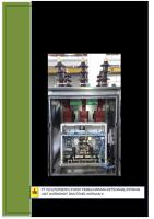
INSTRUCTION FOR CONTROL PANEL (KCAF TYPE) MODULES The panel contains module(s) according to the quantity of anode. These modules require no maintenance. Each module controls one pair of anodes or each anode via front mounted amperage selector knobs. The current level for each anode is shown on the digital display above each selector knob. Below each digital display unit there is a red led alarm indicator, which will illuminate if module(s) has failure causing either zero current or over current output. FIXING Two mounting bars with four holes for M10 are incorporated on the back plate of the panel. We recommend a bulkhead mounting in close proximity to the anodes to avoid voltage drop and cutting cable run costs. MAIN POWER SUPPLY CABLE Run cable from available power source .... via gland to terminal marked 'Mains In'. Be sure to connect correct cable to terminal. SETTING UP Once the cables have been run and connected, the System is ready to be switched on. NOTE - the following procedure can only be carried out with the anodes in seawater. 1.
Turn up the switch at the left-low side of control panel. A green neon on the right of switch will light up to confirm power on.
2.
Set all anode currents by turning the knobs unless the readings of digital display correspond to each current specified in Operation Manual.
3.
Switch off until ship’s engine starts and switch on when seawater pumps are running.
-4-
K.C. LTD.
MGPS DOCUMENT REV(A) : 99/06/18
FOR KF ANODE
INSTRUCTION FOR FITTING ANODES (JIS 10K-150A FLANGE WITH PIPE UPSTAND TYPE) Before works, make sure anode overhaul height by the length of anode & mounting sleeve over the sea chest / strainer top. 1.
Pipe upstand (150A #40) to be supplied and fitted by client. Pipe to have minimum bore of 145mm inside after coating or lining to ensure clearance of anode mounting assembly. Flange to be JIS 10K-150A. If K.C. Ltd. have supplied drawings for specific system. Burn a hole in the sea chest / strainer top plate to suit outside diameter of pipe in position stated on drawing. If K.C. Ltd. have not supplied drawings. Determine the position of the pipe upstand and burn a hole in the top plate of the sea chest / strainer to suit pipe outside diameter. The anodes must be positioned between the sea water inlet grid and suction pipes in the sea chest in case anode are installed in sea chest. Recommended minimum dimensions for anode positioning 300mm between anode center and anode center and 120mm between anode center and the nearest steelwork. Weld pipe upstand in position, ensuring:-
1.1 Pipe is welded to the sea chest / strainer top plate on both top and bottom surfaces. 1.2 Flange top surfaces must be horizontal unless otherwise stated. 1.3 We recommend that any special paint or coating applied to the sea chest is also applied to the pipe upstand. 2.
Bolt flange mounting complete with anode to mating flange on pipe upstand. Remember to fit gasket between flanges and ensure no mechanical load is applied to cable.
-5-
K.C. LTD.
MGPS DOCUMENT REV(C) : 16/04/04
WIRING OF SYSTEM Client to supply all cables and connection boxes between :1.
Power isolation switch and control panel.
2.
Control panel and anodes including earth return leads.
Minimum Recommended Cable Specification Marine rubber double insulated. Use one core per anode and one core per earth return. The minimum core size for all cable is as follows : 0 25 50
-
25 50 100
metre cable run metre cable run metre cable run
Use 2.5 sq mm core. Use 4.0 sq mm core. Use 6.0 sq mm core.
Each anode is assembled with different cable color for easy identification as follows; CU (Copper) Anode cable
- Red
AL (Aluminium) Anode Cable - Blue
-6-
K.C. LTD.
MGPS DOCUMENT REV(B) : 20/10/03
WIRING UP An earth (-ve) return must be installed at each separate anode location i.e. if the system supplied is designed for 2 sea chests/strainers then 2 earth returns must be used. Use a min of 1 earth return for every 4 Anodes. Ensure that a separate core of a multicore cable or a completely separate cable is used for this purpose. Use cable as specified above. Connect to the terminals available in the rear of the control unit marked 'earth returns'. We suggest the cable connections are made by welding a bolt on to the strainer or sea chest close to the anodes (but no nearer than 250mm). Fit junction box close to anodes and wire to control panel using recommended cable as per attached wiring diagram and control box drawing. After switching on, check the polarity of the anodes in relation to the hull. All anodes are to be positive, relative to a negative hull.
TROUBLESHOOTING NO LIGHTS ON AT ALL 1. Check mains fuse in the front of the control panel(above on - off switch). 2. Check circuit breaker in distribution box. 3. Check if anodes are immersed in the sea water. ANY ONE DIGITAL DISPLAY WILL NOT SHOW A READING 1. Check anode fuse inside the module. 2. Check if any cable has been severed. 3. Check anode lead joint. 4. Check if inside sea chest/strainer is filled with air. 5. Change over any two modules to check if fault is in module or rest of system. ALARM LED LIGHTS UP 1. Check if digital display is showing zero or max current. 2. If digital display is not showing a reading but led is light, module is fault. And then return K.C. LTD. for repair.
-7-
K.C. LTD.
MGPS DOCUMENT REV(B) : 03/02/25
IN-SERVICE INSTRUCTIONS DESCRIPTION Once the System has been installed it will perform two functions : 1.
Eliminate marine growth and reduce the corrosion rate in the seawater service lines.
2.
The System uses impressed current sacrificial anodes which last to designed life. Once in service the anodes will require renewal within designed life. Refer to instruction of anode renewal as specified separately. Please ensure a reasonable dispatch time when ordering replacement anodes.
You will require the following : ANODE
PART No.
Q’TY
CU (Copper)
KFCU 790
2
AL (Aluminium)
KFAL 790
2
ANODE LOCATION STRAINER
When ordering, inform of maker's reference number specified on the cover sheet of this drawing. ADJUSTMENTS The control panel is fully automatic and therefore does not require any adjustments in service. CHECKING We suggest that as a matter of course the Control Panel should be checked every week. When checking, see that all the digital display ammeters are working, this will determine all is correct. When the anodes have nearly wasted, the digital display above the corresponding anode will start to fall. When this happens, turn the anode current knob back to zero and leave it until the anode renewal. Reset once again at sea after renewal to current settings given previously. WARNING (In case anodes are installed in strainer) When opening the strainer lid for regular check inside strainer, do not fail to remove all anodes mounted onto the lid. Lifting up strainer lid without anodes removal and lifting it down gives serious stress to stud and results in anode breakage.
-8-
K.C. LTD.
MGPS DOCUMENT REV(A) : 99/06/18
IN-SERVICE ADJUSTMENT AND CURRENT SETTINGS The effective working of the system can only be determined by inspection and it is suggested that if after some 6 months of operation the opportunity to examine a strainer, length of pipe or heat exchanger, presents itself, this should be done. In the event of there being signs of infestation, the current to each anode in this section should be increased by a maximum of 0.4 amps, but if no fouling is present the current to each anode within this section may be reduced by a maximum of 0.2 amps. This routine can be repeated at intervals, the current being adjusted accordingly. NOTE : The higher the current setting the shorter the anode life. The lower the current setting the greater the anode life. ANODE POSITION : STRAINER ANODE REF
CURRENT SETTINGS
PORT CU 1 AL 1
2.3 Amps 2.5 Amps
STB’D CU 2 AL 2
2.3 Amps 2.5 Amps
NOTE : Turn the current setting down to 0.8 Amp for the strainer not in use but be sure to return to operating current as above when the strainer comes in use. CAUTION
Customers are recommended for the purchase of genuine parts from us. Imitated parts make the system get fatally damaged.
-9-
K.C. LTD.
MGPS DOCUMENT REV(A) : 05/05/09
CURRENT SETTINGS AFTER ANODE RENEWAL
On renewal of spare anode current settings should be adjusted according to following steps. 1.
Secure main power is off.
2.
Secure all electric connection is tightened, particularly earth cable.
3.
Secure anodes are immersed in sea water.
4.
Turn the current setting knob of control panel clockwise till the mid position.
5.
Turn power on.
6.
Set normal current settings in this manual.
7.
Keep current settings on above 0.3 Amp(min. current for residual dosage). Otherwise system may trip off.
- 10 -
K.C. LTD.
MGPS DOCUMENT REV(A) : 99/06/18
INSTRUCTIONS OF ANODE RENEWAL Life of anodes is designed specified in specification, but it will be more or less depending upon the operation of the vessel and it will be noticed timing of anode exchange from falling down of digital display of each anode on control panel. Exchange of anodes can be carried out as following procedures. K.C. Ltd. provide renewal anodes in a complete assembled set including all accessories, flange and cable. So customer is required to disconnect anode cable and flange bolts only for replacement. NOTE Anode positioned in sea chest : Renewal to be done during dry dock. Anode positioned in strainer : Renewal to be done in afloat. Prior to works secure sea valves are firmly closed. 1.
Switch off main power supply on the control unit.
2.
Disconnect anode cable in junction boxes.
3.
Remove anode flange together with used anode from sea chest or strainer.
4.
Mark anode kind on counter flange.
5.
Install new anodes and connect up anode cables. Be sure to connect correct anode and to put gaskets between anode flanges.
6.
Connect anode cable in junction box at the correct position and switch on control panel when sea water pumps are running.
7.
Ensure current on control panel showing setting value given previously.
- 11 -
K.C. LTD. SPECIFICATION FOR M.G.P.S Client
Daewoo Shipbuilding & Marine Engineering Co., Ltd.
Project No
H 5197/5270/5271
Sea water to be treated
2,200 m3/h from either of 2 strainers
Weight required for system per strainer
2 ppb×2,200m3/h×5 years ×24 hours ×365 days×10-6 = 192.7 Kg AL(Aluminium) : 0.5 ppb×2,200m3/h×5 years ×24 hours ×365 days ×10-6 = 48.14 Kg
Weight provided
CU(Copper)
by K.C. LTD.
AL(Aluminium) :
CU(Copper)
:
:
790 mm×135ø ×2 = 202.6 Kg 790 mm×135ø ×2 =
64.6 Kg
per strainer Anode location
1 Cu×1 Al in each of 2 strainer
Anode mounting type
JIS 10K-150A flange mounting sleeve 2 ×KFCU790 (Copper) anodes ass’y for 2.5 year working
Scope of supply
2 ×KFAL790(Aluminium) anodes ass’y for 2.5 year working 2 ×KFCU790 (Copper) anodes ass’y for 2.5 year spare 2 ×KFAL790 (Aluminium) anodes ass’y for 2.5 year spare 1 ×KCAF3040 control panel with cable glands 2 ×Plug & receptacle for anode cable connection 1 ×Set standard spares
Painting colour
Control panel to Munsell 7.5 BG 7/2
Electric source
AC 220V, 60Hz, 1PH
Electric power consumption
Max 180 Watt
Life time of anodes
Remark
5 years (2.5 years with working anodes + 2.5 years with spare anodes) Our spare anodes are supplied in a completely assembled set including all isolation materials, flange, cable and etc. for easy replacement and perfect insulation. - 12 -
K.C. LTD. SCOPE OF SUPPLY AND WEIGHTS PER HULL
S/N
Item
Type
Q’ty
Wt. Each
Total weight
①
Cu(Copper) anode Ass’y for working
KFCU 790
2pc
122.8 kg
245.6 kg
②
Al(Aluminium) anode Ass’y for working
KFAL 790
2pc
53.7 kg
107.4 kg
③
Cu(Copper) anode Ass’y for spare
KFCU 790
2pc
122.8 kg
245.6 kg
④
Al(Aluminium) anode Ass’y for spare
KFAL 790
2pc
53.7 kg
107.4 kg
⑤
Control Panel
KCAF3040
1pc
20.0 kg
20.0 kg
④
Plug & Receptacle
MJ05
2pc
2.0 kg
4.0 kg
⑤
On board spares
-
1set
Total net weight of system
730.0 kg
ON BOARD SPARES Only spares required for first 5 years operation are : 2 off 5 amp fuses for control panel modules and 2 off 2.5 amp fuses for control panel power unit &1 power on led, spares are supplied with separate spare box . For replacement anodes required after 2.5 years. replace on board spare anodes for futher 2.5 years working. After 5 years working, replacement anodes required (see list above). Replacement anode or guarantee work if required contact : K.C LTD. (see first page)
- 13 -