![PCS-9611S X Communication Protocol Manual en Overseas General X R1.20 [PDF]](https://pdfs.asia/img/200x200/pcs-9611s-x-communication-protocol-manual-en-overseas-general-x-r120.jpg)
4 0 4 MB
Copyright © 2021 NR. All rights reserved. NR, the NR logo are either registered trademarks or trademarks of NR Electric Co., Ltd. No NR trademarks may be used without written permission. NR products appearing in this document may be covered by P.R. China and foreign patents. NR Electric Co., Ltd. reserves all rights and benefits afforded under P.R. China and international copyright and patent laws in its products, including but not limited to software, firmware and documentation. NR Engineering Co., Ltd. is licensed to use this document as well as all intellectual property rights owned or held by NR Electric Co., Ltd, including but not limited to copyright, rights in inventions, patents, know-how, trade secrets, trademarks and trade names, service marks, design rights, database rights and rights in data, utility models, domain names and all similar rights. The information in this document is provided for informational use only and does not constitute a legal contract between NR and any person or entity unless otherwise specified. Information in this document is subject to change without prior notice. To the extent required the products described herein meet applicable IEC and IEEE standards, but no such assurance is given with respect to local codes and ordinances because they vary greatly. Although every reasonable effort is made to present current and accurate information, this document does not purport to cover all details or variations in equipment nor provide for every possible contingency to be met in connection with installation, operation, or maintenance. Should further information be desired or should particular problems arise which are not covered sufficiently for your purposes, please do not hesitate to contact us.
Preface
Preface About This Document This manual describes the network structures and the communication protocols supported by the device. To start using this manual, user should have a basic knowledge of communication in substation automation system (SAS) and of the specific communication protocols along with the basic operation methods of the PCS-Studio configuration tool for PCS S series IEDs.
Safety Information This manual is not a complete index of all safety measures required for operation of the equipment (module or device). However, it comprises important information that must be followed for personal safety, as well as to avoid material damage. Information is highlighted and illustrated as follows according to the degree of danger: Indicates an imminently hazardous situation that, if not avoided, will result in death or serious injury. Indicates a potentially hazardous situation that, if not avoided, could result in death or serious injury. Indicates a potentially hazardous situation that, if not avoided, may result in minor or moderate injury or equipment damage. Indicates that property damage can result if the measures specified are not taken.
Important information about the product, please pay attention to avoid undesired result.
Instructions and Warnings The following hazard statements apply to this device.
Disconnect or de-energize all external connections BEFORE opening this device. Contact with hazardous voltages and currents inside this device PCS-9611S Feeder Relay
I Date: 2021-01-08
Preface
can cause electrical shock resulting in injury or death.
Contact with instrument terminals can cause electrical shock that can result in injury or death.
Use of this equipment in a manner other than specified in this manual can impair operator safety safeguards provided by this equipment.
Have ONLY qualified personnel service this equipment. If you are not qualified to service this equipment, you can injure yourself or others, or cause equipment damage.
This device is shipped with default passwords. Default passwords should be changed to private passwords at installation. Failure to change each default password to a private password may allow unauthorized access. NR shall not be responsible for any damage resulting from unauthorized access.
DO NOT look into the fibre (laser) ports/connectors.
DO NOT look into the end of an optical cable connected to an optical output.
DO NOT perform any procedures or adjustments that this instruction manual does not describe.
During installation, maintenance, or testing of the optical ports, ONLY use the test equipment qualified for Class 1 laser products!
PCS-9611S Feeder Relay
II Date: 2021-01-08
Preface
Incorporated components, such as LEDs, transceivers, and laser emitters, are NOT user serviceable. Return units to NR for repair or replacement.
Equipment components are SENSITIVE to electrostatic discharge (ESD). Undetectable permanent damage can result if you do not use proper ESD procedures. Ground yourself, your work surface, and this equipment BEFORE removing any cover from this equipment. If your facility is not equipped to work with these components, contact NR about returning this device and related NR equipment for service.
Insufficiently rated insulation can deteriorate under abnormal operating conditions and cause equipment damage. For external circuits, use wiring of SUFFICIENTLYRATED insulation that will not break down under abnormal operating conditions.
SEVERE power and ground problems can occur on the communications ports of this equipment as a result of using non-standard cables. Please use the wiring method recommended in the manual for communication terminals.
DO NOT connect power to the device until you have completed these procedures and receive instruction to apply power. Equipment damage can result otherwise.
Use of controls or adjustments, or performance of procedures other than those specified herein, may RESULT IN hazardous radiation exposure.
The firmware may be upgraded to add new features or enhance/modify existing features, please MAKE SURE that the version of this manual is compatible with the product in your hand. PCS-9611S Feeder Relay
III Date: 2021-01-08
Preface
Document Conventions ⚫
Menu path is connected with the right arrow "→" and bold. For example: the access path of protection settings is: Main Menu → Settings → Protection Settings.
⚫
Settings out of list should be placed in brackets. For example: the system setting [Opt_SysFreq]
⚫
Cross-references are presented in italics. For example: refer to Figure 1.1-1, refer to Table 1.1-1, reference to Section 1.1
⚫
Binary input signals, binary output signals, analogue quantities, LED lights, buttons, and other fixed meanings, should be written in double quotes and bold. For example: press the "ENT" button.
Warranty This product is covered by the standard NR 10-year warranty. For warranty details, please consult the manufacturer or agent for warranty information.
Document Structure This manual is a comprehensive work covering all aspects of device communication interfaces and protocols. Read the sections that pertain to your application to gain valuable information about communication the device. To concentrate on the target sections of this manual as your job needs and responsibilities dictate. An overview of each manual section and section topics follows.
1
Communication Modules Introduction of communication interfaces application in different network structures and serial connection modes.
2
IEC 61850 Introduction of IEC 61850 protocol, including protocol characteristics and properties. Instantiation application of communication between the client and the server for substation automation via the IEC 61850 Manufacturing Message Specification (MMS) protocol, cross communication between devices via Generic Object-Oriented Substation Event (GOOSE) messages and IEC 61850-9-2 SV implementation.
3
DNP3 Introduction of DNP3 protocol characteristics and properties, especially the application layer with implementation information.
PCS-9611S Feeder Relay
IV Date: 2021-01-08
Preface
4
IEC 60870-5-103 Instruction concentrating on vendor-specific implementations of IEC 60870-5-103 protocol.
5
Modbus Introduction of Modbus protocol main function codes.
6
C37.113 Introduction of communication protocol mode and message frame format of synchrophasor measurement conforming to the IEEE C37.113 standard.
ANNEX A PICS Protocol Implementation Conformance Statement (PICS)
ANNEX B MICS Model Implementation Conformance Statement (MICS)
ANNEX C TICS Technical Issues Conformance Statement (TICS)
ANNEX D PIXIT Protocol Implementation eXtra Information for Testing (PIXIT)
Document Revision History P/N: ZL_PCS-9611S_X_Communication Protocol Manual_EN_Overseas General_X Current Version: R1.20 Version Release Date Document
Firmware
R1.00
R1.13
2019-12-16
Description of change
Form the original manual.
PCS-9611S Feeder Relay
V Date: 2021-01-08
Preface
R1.10
R1.16
⚫
Update of supporting interface of DNP3;
⚫
Addition of port bonding state;
⚫
Revision of Ethernet connection parameters;
⚫
Addition of annex of device applicable PICS, MICS, TICS & PIXIT;
⚫
Addition of description of PRP/HSR networking mode mismatch alarm;
⚫
Addition of switch requirements in HSR-structured network;
⚫
Revision of MMS Communication Network Deployment;
⚫
Specifying of protocol relevant settings;
⚫
Addition of device-supported IEC 61850 service;
2020-08-04
Addition of GOOSE & SV processing mechanism for invalid data and maintenance state;
R1.20
R1.17
2021-01-08
⚫
The PMU network structure is added;
⚫
The description of C37.113 communication protocol is added;
⚫
The settings [En_LAN1], [En_IP_Whitelist] and [IP**_Whitelist] in “General Communication Settings” are added;
⚫
The setting range of [Addr_RS485-1] and [Addr_RS485-2] in “General Communication Settings” is modified;
⚫
The setting [Opt_DualNetMode_MMS] Communication Settings” is modified;
⚫
Rename the settings [Threshold_Measmt_Net] and [ThAbs_Measmt] in “IEC 61850 Communication Settings”;
⚫
The setting [En_UR_TCP*_DNP] in “DNP Communication Settings” is modified;
⚫
Rename the setting [Threshold_Measmt_Net] in “IEC 60870-5-103 Settings”;
⚫
The setting [En_IEC103_TCP&UDP_Port] 60870-5-103 Settings” is added;
⚫
The setting [En_Modbus_TCP_Port] Communication Settings” is added;
in “IEC 61850
in
in
“IEC
“Modbus
PCS-9611S Feeder Relay
VI Date: 2021-01-08
1 Communication Modules
1
1 Communication Modules Table of Contents 1.1 CPU Module ..................................................................................................... 1-1 1.2 Communication Applications ......................................................................... 1-2 1.3 Ethernet Network Structures .......................................................................... 1-3 1.3.1 Standardized Ethernet Cable ............................................................................................... 1-4 1.3.2 Relevant Settings ................................................................................................................. 1-4 1.3.3 Ethernet Interface Setup ...................................................................................................... 1-5 1.3.4 Port Bonding Operation ........................................................................................................ 1-6 1.3.5 Star-shaped .......................................................................................................................... 1-7 1.3.6 PRP Structure....................................................................................................................... 1-8 1.3.7 HSR Structure .................................................................................................................... 1-10 1.3.8 RSTP Ring Structure .......................................................................................................... 1-12
1.4 Serial Connection .......................................................................................... 1-12 1.4.1 Relevant Settings ............................................................................................................... 1-12 1.4.2 EIA-485 Interface ............................................................................................................... 1-13
PCS-9611S Feeder Relay
1-a Date: 2021-01-08
1 Communication Modules
1
PCS-9611S Feeder Relay
1-b Date: 2021-01-08
1 Communication Modules
This section outlines the communication modules of device. This device supports a choice of multiple protocols via rear interfaces on communication modules. The protocols are selected and configured by setting or configuration file via the configuration tool PCS-Studio. It should be noted that the description contained within this manual do not aim to fully detail protocols. The relevant documentation for protocols should be referred to for such goal. This manual serves to describe the specific implementation of protocols in this device.
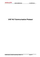
1.1 CPU Module This device is usually ordered with factory-installed communication modules. Yet a communication module, such as the CPU module or the NET-DSP module, can also be installed and replaced in the device afterwards. The NR6106 CPU module can be installed on device rack. The sub-models of this module correspond to different communication interfaces or device variants.
1
2
3
4
Figure 1.1-1 View of CPU module
PCS-9611S Feeder Relay
1-1 Date: 2021-01-08
1
1 Communication Modules
2. Ethernet interfaces LAN3 and LAN4 3. Serial interfaces: 10-terminal connector, 2*EIA-485 ports and 1*EIA-485/TTL port for clock synchronization 4. Debugging interface: RJ45 port for serial connection
Debugging interface
Serial Interfaces
Communication interface
Ethernet Interfaces 3&4
1.2 Communication Applications Ethernet Interfaces 1&2
1
1. Ethernet interfaces LAN1 and LAN2
Physical Connection 2 × copper Ethernet, 100Base-TX, RJ45
●
2 × optical Ethernet, 100Base-FX, 1310 nm, duplex LC plug, 2 km via 50 µm or 62.5 µm multi-mode optical fibre, SFP socket
●
●
1 × EIA-485, 3-terminal
●
1 × EIA-232/485, 3-terminal
●
1 × EIA-485/TTL, 4-terminal
● ●
1 × RS-232, RJ45 Application IEC 61850 Ed1.0
●
●
IEC 61850 Ed2.0
●
●
IEC 61850-8-1 MMS server
●
●
IEC 61850-9-2LE SV
●
●
IEC 61850-8-1 GOOSE
●
●
IEC 60870-5-103
●
●
DNP3
●
●
Modbus
●
●
●
●
IRIG-B 485/TTL, PPS/PPM
●
Printer, serial
●
PCS-9611S Feeder Relay
1-2 Date: 2021-01-08
Debugging interface
Serial Interfaces
Communication interface
Ethernet Interfaces 3&4
Ethernet Interfaces 1&2
1 Communication Modules
●
Debugging Additional Ethernet protocols and services RSTP (Ethernet ring redundancy)
●
PRP (Parallel Redundancy Protocol)
●
HSR (High-availability uninterruptible ring redundancy)
●
SNTP (time synchronization via Ethernet)
●
●
IEEE 1588v2 (PTP protocol via Ethernet)
●
●
Port bonding
●
●
1.3 Ethernet Network Structures The Ethernet interfaces have an integrated switching function. This makes it possible to integrate the device with third-party components into almost all network structures, which are independent of the communication protocols such as IEC 61850, IEC 60870-5-103 and DNP3. Devices are integrated into superior network structures via switches. Each switch provides several interfaces to connect to devices and other switches in the superior network. The superior network operates on the basis of RSTP (Rapid Spanning Tree Protocol) which leads to a network or a ring of such network switches. This results in a variety of possible structures of superior network. Control Centre LAN
WLAN Remote Monitoring Substation LAN
IEDs
Figure 1.3-1 Ethernet network structure
PCS-9611S Feeder Relay
1-3 Date: 2021-01-08
1
1 Communication Modules
1
1.3.1 Standardized Ethernet Cable It is recommended to use screened twisted multi-strand network cable (category 5) as the communication cable.
Figure 1.3-2 Ethernet cable
1.3.2 Relevant Settings The communication settings that are relevant to Ethernet network are listed in the following table. Refer to the device technical manual and setting guide for more detail about the parameterization, such as IP address, gateway address, etc. Access path: Main Menu Settings Global Settings Comm Settings General Comm Settings No.
Settings
1
IP_LAN1
2
Mask_LAN1
3
En_LAN1
4
IP_LAN2
5
Mask_LAN2
6
En_LAN2
7
IP_LAN3
8
Mask_LAN3
9
En_LAN3
10
IP_LAN4
11
Mask_LAN4
12
En_LAN4
13
Gateway
14
Baud_Printer
15
En_AutoPrint
16
Protocol_RS485-1
Range 0.0.0.0~ 255.255.255.255 0.0.0.0~ 255.255.255.255 Disabled Enabled 0.0.0.0~ 255.255.255.255 0.0.0.0~ 255.255.255.255 Disabled Enabled 0.0.0.0~ 255.255.255.255 0.0.0.0~ 255.255.255.255 Disabled Enabled 0.0.0.0~ 255.255.255.255 0.0.0.0~ 255.255.255.255 Disabled Enabled 0.0.0.0~ 255.255.255.255 4800; 9600; 19200 38400; 57600; 115200 Disabled Enabled IEC103 Modbus
Default value
Unit
Step
198.120.0.100
-
-
255.255.0.0
-
-
Enabled
-
-
198.121.0.100
-
-
255.255.0.0
-
-
Enabled
-
-
198.122.0.100
-
-
255.255.0.0
-
-
Disabled
-
-
198.123.0.100
-
-
255.255.0.0
-
-
Disabled
-
-
0.0.0.0
-
-
19200
bps
-
Disabled
-
-
IEC103
-
-
Remark IP address of Ethernet port A Subnet mask of Ethernet port A Put Ethernet port A into service IP address of Ethernet port B Subnet mask of Ethernet port B Put Ethernet port B into service IP address of Ethernet port C Subnet mask of Ethernet port C Put Ethernet port C into service IP address of Ethernet port D Subnet mask of Ethernet port D Put Ethernet port D into service IP address of the gateway (router) Baud rate of printer port Enable/disable automatic printing function Communication protocol of rear RS-485 serial port 1. IEC103: IEC60870-5-103 protocol Modbus: Modbus protocol PCS-9611S Feeder Relay
1-4 Date: 2021-01-08
1 Communication Modules No.
Settings
17
Protocol_RS485-2
18
Baud_RS485-1
19
Baud_RS485-2
20
Addr_RS485-1
21
Range
Default value
IEC103 Modbus
Unit
Step
IEC103
-
-
19200
bps
-
19200
bps
-
1~254
100
-
1
Addr_RS485-2
1~254
100
-
1
22
IP_SyslogServer**
0.0.0.0~ 255.255.255.255
0.0.0.0
-
-
23
Cfg_NetPorts_Bond
0~255
0
-
-
B01.Opt_NetMode
Normal; 1-2:Normal,3-4:HSR; 1-2:Normal,3-4:PRP; 1-2:Normal,3-4:RSTP
Normal
-
-
24
4800; 9600; 19200 38400; 57600; 115200 4800; 9600; 19200 38400; 57600; 115200
25
En_IP_Whitelist
Disabled Enabled
Disabled
-
-
26
IP**_Whitelist
000.000.000.000~ 255.255.255.255
0.0.0.0
-
-
Remark Communication protocol of rear RS-485 serial port 2. IEC103: IEC60870-5-103 protocol Modbus: Modbus protocol Baud rate of rear RS-485 serial port 1. Baud rate of rear RS-485 serial port 2. Communication address between the device and the SCADA or RTU via RS-485 serial port 1. Communication address between the device and the SCADA or RTU via RS-485 serial port 2. The setting is used to set IP address of syslog server ** (**=01~04), and the device can upload audit log to syslog server. The setting is invalid unless cyber security is configured in the device. Syslog is a communication protocol for message logging, it is used for security auditing in this device. The setting is used to set the Ethernet ports that are used as hot standby each other. The network method of the CPU module located in slot No.1 A whitelist is a list of IP addresses that are granted access to a certain system or protocol. When a whitelist is used, all IP addresses are denied access, except those included in the whitelist. This setting is used to enable/disable the whitelist function of this device. No.** IP address of the whitelist. (**=01...16) This setting is effective only when the setting [En_IP_Whitelist] is enabled.
1.3.3 Ethernet Interface Setup The communication modules and interfaces are available in both electrical and optical versions. There is no difference in interface setup through both versions. To communicate with the device via a PC for monitoring, a connection must be established. Ensure that the device and PC are in the same network segment by setting the IP address
PCS-9611S Feeder Relay
1-5 Date: 2021-01-08
1
1 Communication Modules
1
[IP_LAN*] and subnet mask [Mask_LAN*] of corresponding Ethernet interfaces.
LAN1 LAN2 LAN3
LAN4
Figure 1.3-3 Ethernet interfaces
For example, to establish a connection between PC and the device first Ethernet interface, set the IP address and subnet mask of PC to be “198.87.96.102” and “255.255.255.0”.The IP address and subnet mask of device should be [IP_LAN1]= 198.87.96.*** (** can be any integer from 1 to 254 except 102 or any other appeared number), [Mask_LAN1]=255.255.255.0.
The logic setting [En_LAN*] must be enabled to activate the corresponding Ethernet interface of device.
1.3.4 Port Bonding Operation Use the setting [Cfg_NetPorts_Bond] to set the channel bonding arrangement of two Ethernet ports in station level communication link. In this operating mode, two interfaces of the device are bonding with the same IP and MAC address. The 1st interface that detects a connection with switch is active and takes the responsibility of the entire data transmission via such connection. The 2nd interface whose link status is monitored operates on standby. If the active connection fails, the device switches to the 2nd one rapidly. For redundancy or increased throughput of the communication, dual network structure may be
PCS-9611S Feeder Relay
1-6 Date: 2021-01-08
1 Communication Modules
adopted along with channel bonding technology. These two bonded interfaces, who share the identical IP address and MAC address, work in Active-Standby mode. If the link via active interface fails, the link via original standby interface will be activated automatically to ensure a reliable communication. The value of this setting represents a 4-bits binary number. Each bit represents a corresponding Ethernet port's bonding status. Use the following map to decide the specific setting value. Additionally, the default value "0" means the channel bonding function is deactivated.
Ethernet port 1 Port 4 Port 3 Port 2 Port 1 Bit 3
Bit 2
Bit 1
Bit 0
0
0
1
1
Binary
Setting Value
0011
3
Port 4 Port 3 Port 2 Port 1
Bonding
Bonding
Bit 3
Bit 2
Bit 1
Bit 0
1
0
0
1
Binary
Setting Value
1001
9
Ethernet port 2 Port 4 Port 3 Port 2 Port 1 Bit 3
Bit 2
Bit 1
Bit 0
0
1
0
1
Binary
Setting Value
0101
5
Port 4 Port 3 Port 2 Port 1
Bonding
Bonding
Bit 3
Bit 2
Bit 1
Bit 0
0
1
1
0
Binary
Setting Value
0110
6
Ethernet port 3 Port 4 Port 3 Port 2 Port 1 Bit 3
Bit 2
Bit 1
Bit 0
1
0
1
0
Binary
Setting Value
1010
10
Port 4 Port 3 Port 2 Port 1
Bonding
Bonding
Bit 3
Bit 2
Bit 1
Bit 0
1
1
0
0
Binary
Setting Value
1100
12
Ethernet port 4
CPU Module
The Active-Standby mode switching logic is: Take the device Ethernet ports 1 & 2 for example and assume that port 1 is connected to network 1 while port 2 is connected to network 2. ⚫
After the device is powered on, only port 1 is activated when both network 1 and network 2 are normal.
⚫
If network 1 is abnormal, port 2 will be activated if network 2 is normal.
⚫
If network 1 is abnormal, port 2 cannot be activated if network 2 is also abnormal. The device will keep trying on port 1.
⚫
If port 2 is working, the device will maintain this state even if network 1 has been restored to normal. It will be switched to port 1 only if network 2 is abnormal.
1.3.5 Star-shaped Set [B01.Opt_NetMode] to be "Normal" to activate this structure. Only one interface of the device is connected to switch. Multiple devices are connected to the switch in a star-shaped connection.
PCS-9611S Feeder Relay
1-7 Date: 2021-01-08
1
1 Communication Modules
1
Switch1
Switch2
Substation LAN
IEDs Figure 1.3-4 Star-shaped network
The unique connection provides no redundancy. Practically, it is suggested to use another interface to create a dual star network or at least use the port bonding method to enhance the redundancy of network structure.
1.3.6 PRP Structure Set [B01.Opt_NetMode] to be "1-2: Normal, 3-4: PRP" to activate this structure with the device No.3 & 4 Ethernet interfaces. According to IEC 62439-3, the PRP (Parallel Redundancy Protocol) provides communication over two independent networks simultaneously. If there is an interruption in communication on either network A or network B, the data exchange continues without problems on the other network. Thus, it assures that there is no interruption. It is recommended to use a non-PRP device, such as debugging PC, with a Redundancy Box (RedBox) in a PRP network. The PRP nodes connect to two independent networks, and send two copies of the same packet to both networks. Both networks transmit these messages to receiving nodes, while receiving nodes accept the first packet and discard the second. The receiving nodes make a redundant handling at data link layer to realize redundant message receiving and then transmit data to application layer.
PCS-9611S Feeder Relay
1-8 Date: 2021-01-08
1 Communication Modules
Switch1
1
Switch2
Substation LAN
LAN A
LAN B
PRP Activated
Substation LAN
LAN A
LAN B
LAN A
PRP Activated
LAN B
PRP Activated
LAN A
LAN B
PRP Activated
IEDs Figure 1.3-5 PRP structure network
Each node has two interfaces that operate in parallel and that are attached to the same upper layers of the communication stack through the Link Redundancy Entity (LRE). For the basic communication, the LRE presents toward its upper layers the same interface as a non-redundant network adapter, so the upper layers are unaware of redundancy. When receiving a frame from the node’s upper layers, the LRE appends to the frame a Redundancy Check Trailer (RCT) containing a sequence number and sends the frame through both its ports at nearly the same time. The two frames are nearly identical except for the LAN identifier (and the checksum). When receiving frames from the network, the LRE forwards the first received frame of a pair to its node’s upper layers and discards the duplicate frame (if it arrives). It removes the RCT if required. This general PRP operating mode does not apply to PTP frames, since the delay suffered by a frame is not the same in the two LANs and some frames are modified in the TCs Since the RCT of PRP cannot be relied upon for PTP messages. As ordinary clocks don't perform duplicate discard on them and consider the two ports as independent. The device will automatically check whether its setting value of PRP networking mode matches the actual network networking mode. If it does not match, the device will issue the "Alm_NetMode_Unmatched" alarm. If there is such alarm, please check the [B01.Opt_NetMode] setting value.
PCS-9611S Feeder Relay
1-9 Date: 2021-01-08
1 Communication Modules DANP 1
1 upper layer
DANP 2
UDP
TCP
hard real-time stack
UDP
network layer
same data link layer interface
network adapters
network layer
Link Redundancy Entity
Port A Tx
Link Redundancy Entity
Port B Rx
TCP
hard real-time stack
Tx
Port A Rx
Tx
Port B Rx
Tx
Rx
transceivers
LAN A LAN B
Figure 1.3-6 Operation mechanism of device PRP interfaces
1.3.7 HSR Structure Set [B01.Opt_NetMode] to be "1-2: Normal, 3-4: HSR" to activate this structure with the device No.3 & 4 Ethernet interfaces. According to IEC 62439-3, devices operate in hand-in-hand mode in the HSR (High Availability Seamless Redundancy Protocol) structure to form rings with switches. If an interruption in communication occurs in a network, a seamless switchover takes place. It is recommended to use a non-HSR device, such as debugging PC, with a Redundancy Box (RedBox) in an HSR network. HSR nodes send a copy of data to application layer. The data is copied at data link layer and is transmitted from Port A and Port B via different physical link. HSR ring transmission through two-way link ensures the redundancy of data. When a link fails, a message can be transmitted to the receiving device from another loop, and there is no network reconstruction time. There is no switching network, and forwarding through the device. However, forwarding device has a forwarding delay time per level, so the total forwarding delay is great. This operating mode does not apply to PTP frames, since the delay suffered by a frame is not the same going clockwise or counter-clockwise in the ring. A DANH (Doubly Attached Node implementing HSR) does not receive the same message from both ports since some messages are modified by intermediate nodes.
PCS-9611S Feeder Relay
1-10 Date: 2021-01-08
1 Communication Modules
Switch1
1
Switch2 HSR
Substation LAN
LAN A
Substation LAN
LAN B
LAN A
HSR Activated
LAN B
HSR Activated
LAN A
LAN B
HSR Activated
IEDs Figure 1.3-7 HSR structure network
Each HSR node has two interfaces arranged in a ring. Source nodes send packets over both interfaces. Each node transmits unreceived frames from interface A to interface B and vice versa. The source node removes frames it receives that it injected into the ring. Each HSR node receives two copies of the same packet, and accepts the first packet and discards the second. The accepted packet is transmitted to application layer. For P2P messages (e.g. TCP messages), receiving node will stop transmitting after receiving the message. For multicast or broadcast message, if the message comes from itself, receiving node will stop transmitting after receiving the message. If the message comes from other nodes, receiving node will transmit it to another interface after receiving the message, i.e., receiving message from interface A and transmitting message to interface B. The device will automatically check whether its setting value of PRP networking mode matches the actual network networking mode. If it does not match, the device will issue the "Alm_NetMode_Unmatched" alarm. If there is such alarm, please check the [B01.Opt_NetMode] setting value.
Each node in HSR network transmits messages of all nodes bidirectionally, which brings minor transmission delay and PTP synchronization error. Therefore, in HSR network, it is necessary to reasonably plan the number of HSR nodes according to actual application scenarios. All nodes in the ring network, including Ethernet switch, must meet the standard requirements of HSR. PCS-9611S Feeder Relay
1-11 Date: 2021-01-08
1 Communication Modules
1
1.3.8 RSTP Ring Structure Set [B01.Opt_NetMode] to be "1-2: Normal, 3-4: RSTP" to activate this structure with the device No.3 & 4 Ethernet interfaces. Devices participate in a ring structure via two interfaces. Data is transmitted one by one in the ring until it reaches its intended destination. If the ring structure breaks at a point, stars show up upon the switch quantity. Thanks to RSTP mechanism, the communication may function continuously without interruption. However, a second fault in one star cannot be ignored.
Switch1
Switch2
Substation LAN
Switch3
RSTP Ring LAN A
LAN B
RSTP Activated
LAN A
LAN B
RSTP Activated
LAN A
LAN B
RSTP Activated
IEDs Figure 1.3-8 RSTP ring structure network
1.4 Serial Connection This device provides three EIA-485 ports in a 10-terminal screw connector. The ports are isolated and are suitable for permanent connection of selected protocol. For a serial connection, up to 32 devices can be “daisy chained” together in cascade using a simple twisted-pair electrical connection.
1.4.1 Relevant Settings The communication settings that are relevant to serial connection are listed in the following table. Refer to the device technical manual and setting guide for more detail about the parameterization, such as protocol option, address, baud rate, etc.
PCS-9611S Feeder Relay
1-12 Date: 2021-01-08
1 Communication Modules
Access path: Main Menu Settings Global Settings Comm Settings General Comm Settings No.
Setting
Default
Range
Step
Unit
Remark
-
bps
Baud rate of printer port
-
-
Communication protocol of rear RS-485 serial port 1
-
-
Communication protocol of rear RS-485 serial port 2
-
bps
Baud rate of rear RS-485 serial port 1.
-
bps
Baud rate of rear RS-485 serial port 2.
4800 9600 1
Baud_Printer
19200
19200 38400 57600 115200
2
Protocol_RS485-1
IEC103
3
Protocol_RS485-2
IEC103
IEC103 Modbus IEC103 Modbus 4800 9600
4
Baud_RS485-1
19200
19200 38400 57600 115200 4800 9600
5
Baud_RS485-2
19200
19200 38400 57600 115200
6
Addr_RS485-1
100
1~254
1
-
Communication address between the device and the SCADA or RTU via RS-485 serial port 1.
7
Addr_RS485-2
100
1~254
1
-
Communication address between the device and the SCADA or RTU via RS-485 serial port 2.
1.4.2 EIA-485 Interface Each EIA-485 port has three terminals (two for data transmission and one for signal grounding). It provides a half-duplex fully isolated serial connection to the device. The connection is polarized and whilst the connection diagram indicates the polarization of terminals. Notice that there is no agreed definition of which terminal is which. If the master is unable to communicate with the device and the communication settings match, it is possible that the two-wire connection is reversed.
PCS-9611S Feeder Relay
1-13 Date: 2021-01-08
1
1 Communication Modules
1
EIA-485
EIA-485
EIA-485
TTL
01
A
02
B
03
SGND
04
A
05
B
06
SGND
07
SYN+
08
SYN-
09
SGND
10
SYNTTL
Figure 1.4-1 EIA-485 interfaces
1.4.2.1 Bus Termination The EIA-485 bus must have 120Ω (Ohm) ½ Watt terminating resistors fitted at either end across the signal wires. Some devices may be able to provide the bus terminating resistors by different connection or configuration arrangements, in which case separate external components will not be required. However, this device does not provide such facility. If it is located at the bus terminus, an external termination resistor will be required.
Master
120Ohm
120Ohm
Slave
Slave
Slave
Figure 1.4-2 EIA-485 bus termination
1.4.2.2 Connection Topology The EIA-485 standard requires that each device is directly connected to the physical cable, i.e. the communication bus. Stub and tee are expressly forbidden, such as star topology. Loop bus topology is not part of the EIA-485 standard and is forbidden. PCS-9611S Feeder Relay
1-14 Date: 2021-01-08
1 Communication Modules
Two-core screened cable is recommended. The specification of the cable will be dependent on the application, although a multi-strand 0.5mm2 per core is normally adequate. Total cable length must not exceed 500m. The screen must be continuous and grounded at only one end (normally at the master connection point). For both safety and noise reasons, it is important to avoid circulating current, especially when the cable runs between buildings. The signal grounding connection must have continuity for the benefit of all devices connected to the bus. At no stage must it be connected to the cables screen or to the device chassis. This is for both safety and noise reasons. 1.4.2.3 Biasing It may also be necessary to bias the signal wires to prevent jabber. Jabber occurs when the signal level has an indeterminate state because the bus is not being actively driven. This may occur when all slaves are in receiving mode and the master is slow to turn from receiving mode to transmitting mode. This may be because the master purposefully waits in receiving mode, or even in a high impedance state, until it has something to transmit. Jabber causes the receiving device(s) to miss the first bits of the first character in the packet, which results in rejecting message and no consequential responding of slave. The symptoms of these are poor response time (due to retries), increasing message errors, erratic communication and even a complete failure of communication. Biasing requires that the signal wires be weakly pulled to a defined voltage level of approximate 1V. There should only be one bias point on the bus, which is best situated at the master connection point. The DC source used for the bias must be clean, otherwise noise will be injected. Note that some devices may (optionally) be able to provide the bus bias, in which case external components will not be required.
It is extremely important that the 120Ω termination resistors are fitted. Failure to do so will result in an excessive bias voltage that may damage the devices connected to the bus. As the field voltage is much higher than that required, NR cannot assume responsibility for any damage that may occur to a device connected to the network as a result of incorrect application of this voltage.
Ensure that the field voltage is not being used for other purposes (i.e. powering logic inputs) as this may cause noise to be passed to the communication network.
PCS-9611S Feeder Relay
1-15 Date: 2021-01-08
1
1 Communication Modules
1
1.5 PMU Network Structure According to the IEEE C37.118.2-2011 standard, PMU communication is designed as a client-server communication structure, in which the Phasor Data Concentrators (PDC) functions as both the client and the server. If PDC has successfully connected to PMU, and the PMU configuration CFG-2 has been summoned, PDC will initiate the transmission of synchrophasor data by sending a command to PMU. In substation, the PMU network which is separated from the normal Ethernet network could also adopt the star or ring-shaped network structure. PMU obtains the measured values from measuring points and the precise time from time synchronization source. The time-stamped synchrophasors of current and voltage are formed and transferred together with additional values (such
as
calculated
positive/negative/zero-sequence
phasors,
frequency,
rate-of-change-of-frequency and active/reactive power) via communication module to local PDC in substation or to super PDC of upper level. The following figure shows the typical structure of a Wide Area Measurement System (WAMS) containing PDC and PMU. The data delivered from PMU are transmitted to the control centre through PDC.
Figure 1.5-1 WAMS with PMU
PCS-9611S Feeder Relay
1-16 Date: 2021-01-08
2 IEC 61850
2 IEC 61850 Table of Contents 2.1 Relevant Settings............................................................................................. 2-2 2.2 Communication Profiles ................................................................................. 2-4 2.3 MMS Communication Network Deployment .................................................. 2-5 2.3.1 IEC 61850 Mode .................................................................................................................. 2-5 2.3.2 GB 32890 Mode ................................................................................................................... 2-5
2.4 Server Data Organization ................................................................................ 2-6 2.4.1 Digital Status Values ............................................................................................................ 2-6 2.4.2 Analog Values ....................................................................................................................... 2-6 2.4.3 Protection Logical Nodes ..................................................................................................... 2-8 2.4.4 LLN0 and Other Logical Nodes ............................................................................................ 2-9
2.5 Protocol Properties and Services ................................................................ 2-10 2.5.1 Timestamps ........................................................................................................................ 2-10 2.5.2 Logical Node Name Prefixes.............................................................................................. 2-11 2.5.3 Reporting ............................................................................................................................ 2-11 2.5.4 File Transfer........................................................................................................................ 2-12 2.5.5 Setting Group ..................................................................................................................... 2-12 2.5.6 Log ...................................................................................................................................... 2-12 2.5.7 Generic Object Oriented Substation Events ...................................................................... 2-12 2.5.8 Sampled Value ................................................................................................................... 2-14
2.6 Invalid Data and Link Failure ........................................................................ 2-17 2.7 Processing Mechanism During Network Storm .......................................... 2-18 2.8 Maintenance Mechanism .............................................................................. 2-18 2.9 Protocol Implementation Conformance Statement (PICS) ......................... 2-19 2.10 Model Implementation Conformance Statement (MICS) .......................... 2-19 2.11 TIssues Conformance Statement (TICS) .................................................... 2-19 PCS-9611S Feeder Relay
2-a Date: 2021-01-08
2
2 IEC 61850
2.12 Protocol Implementation eXtra Information for Testing (PIXIT) ............... 2-19
2
PCS-9611S Feeder Relay
2-b Date: 2021-01-08
2 IEC 61850
The IEC 61850 standard is the result of years of work by electric utilities and vendors of electronic equipment to produce standardized communications systems. It is a series of standards describing client/server and peer-to-peer communications, substation design and configuration, testing, environmental and project standards. The complete set includes: ⚫
IEC 61850-1: Introduction and overview
⚫
IEC 61850-2: Glossary
⚫
IEC 61850-3: General requirements
⚫
IEC 61850-4: System and project management
⚫
IEC 61850-5: Communications and requirements for functions and device models
⚫
IEC 61850-6: Configuration description language for communication in electrical substations
2
related to IEDs ⚫
IEC 61850-7-1: Basic communication structure for substation and feeder equipment– Principles and models
⚫
IEC 61850-7-2: Basic communication structure for substation and feeder equipment - Abstract communication service interface (ACSI)
⚫
IEC 61850-7-3: Basic communication structure for substation and feeder equipment– Common data classes
⚫
IEC 61850-7-4: Basic communication structure for substation and feeder equipment– Compatible logical node classes and data classes
⚫
IEC 61850-8-1: Specific Communication Service Mapping (SCSM) – Mappings to MMS (ISO 9506-1 and ISO 9506-2) and to ISO/IEC 8802-3
⚫
IEC 61850-9-2: Specific Communication Service Mapping (SCSM) – Sampled values over ISO/IEC 8802-3
⚫
IEC 61850-10: Conformance testing
These documents can be obtained from the IEC (https://www.iec.ch). It is strongly recommended that all those involved with any IEC 61850 implementation obtain this document set.
PCS-9611S Feeder Relay
2-1 Date: 2021-01-08
2 IEC 61850
Router
SCADA
RTU
IEC 61850 Ed1&2 MMS GOOSE
2 Electrical or Optical
Switch
IEC 61850-9-2 SV GOOSE
IED
IED
IED
Switch
Optical
Merging Unit
Merging Unit
Electronic CT/VT
CB/DS
Figure 2.3-1 Application of IEC 61850 in substation
2.1 Relevant Settings For the adoption of IEC 61850 as the communication protocol of this device, select the option “Basic + IEC 61850 (Edition 1.0 or Edition 2.0)” in the following path through the PCS-Studio configuration tool: Project Name → IED Name → Device Setup → Global Config → MOT → S3 Protocol.
Use the "Edition" option to determine the IEC 61850 protocol edition through the path: Project Name → Communication → IEC61850.
PCS-9611S Feeder Relay
2-2 Date: 2021-01-08
2 IEC 61850
2
Communication Mode
Relevant Settings
Network
IEC61850 Settings & General Comm Settings – IP address, subnet mask and Net mode
Serial connection
Not applicable
Besides the general Ethernet network settings, such IP address, MAC address, the settings that are relevant to this protocol are listed in the following table. Refer to the device technical manual and setting guide for more detail about the parameterization, such as IED name, dual network operation mode, etc. Access path: Main Menu Settings Global Settings Comm Settings IEC61850 Settings No.
Setting
Default
Range
Step
Unit
Remark
1
Pcnt_Deadband
1
0~100.00
0.01
%
It is used to set the change detection threshold for suddenly sending measurement value to the SCADA via the device's Ethernet port using IEC 61850 protocol
2
Threshold_ZeroDrift
0.02
0.001~0.5
0.001
-
Measurement values zero drift suppression threshold
-
If users need to support the quality change upload function, this parameter should be set as “Enabled”
Disabled 3
En_Send_MMS_Qual_Chg
Disabled
Enabled
-
IEC61850 4
Opt_DualNetMode_MMS
IEC61850
GB32890
-
-
It is used to select the network mode of MMS network for the communication with SCADA IEC61850: Network mode with IEC 61850 protocol. GB32890: Network mode with GB32890 standard.
5
IEDNAME
TEMPLATE
-
-
PCS-9611S Feeder Relay
-
The identification of the IED in IEC 61850 protocol. It cannot be an empty string and shall be unique within an SCL file. IEDNAME should be less than 20 characters comprising letters or digits or underline ( _ ), and it is
2-3 Date: 2021-01-08
2 IEC 61850 No.
Setting
Default
Range
Step
Unit
Remark case sensitive. If this setting is modified, the IED name in ".cid" file will be changed simultaneously and vice versa.
2
Disabled 6
En_IEC62351_TCP_Port
Disabled
7
En_IEC61850_TCP_Port
Enabled
Enabled
-
-
The logic setting to enable/disable TCP port in IEC62351 protocol
-
-
The logic setting to enable/disable TCP port in IEC61850 protocol
Disabled Enabled
Access path: Main Menu Settings Global Settings Comm Settings SV Settings No.
Setting
Default
Range
Step
Unit
Remark
-
-
SV receiving mode
NetMode 1
Opt_RecvMode_SV
1
P2P Resv
2
SampleRate_SV
4000
0~65535
1
-
SV sampling rate
3
t_Dly_Interp_Net_SV
2000
1500~15000
1
μs
Delay of interpolation in SV network
4
t_Dly_Interp_P2P_SV
850
600~1500
1
μs
Delay of interpolation in SV peer-to-peer mode
2.2 Communication Profiles This device supports IEC 61850 server services over TCP/IP communication protocol stacks. The TCP/IP profile requires the device to have an IP address to establish communications. These addresses are located in the path: Main Menu → Settings→ Global Settings→ Comm Settings → General Comm Settings. ⚫
MMS protocol IEC 61850 specifies the use of the Manufacturing Message Specification (MMS) at the upper (application) layer for transfer of real-time data. This protocol has been in existence for a number of years and provides a set of services suitable for the transfer of data within a substation LAN environment. IEC 61850-7-2 abstract services and objects are mapped to actual MMS protocol services in IEC 61850-8-1.
⚫
Client/server This is a connection-oriented type of communication. The connection is initiated by the client, and communication activity is controlled by the client. IEC 61850 clients are often substation computers running HMI programs or SOE logging software. Servers are usually substation equipment such as protection relays, meters, RTUs, transformer, tap changers, or bay controllers.
PCS-9611S Feeder Relay
2-4 Date: 2021-01-08
2 IEC 61850
⚫
Peer-to-peer This is a non-connection-oriented, high speed type of communication usually between substation equipment, such as protection relays, intelligent terminal. GOOSE is the method of peer-to-peer communication.
⚫
2
Substation configuration language (SCL) A substation configuration language is a number of files used to describe IED configurations and communication systems according to IEC 61850-5 and IEC 61850-7. Each configured device has an IED Capability Description (ICD) file and a Configured IED Description (CID) file. The substation single line information is stored in a System Specification Description (SSD) file. The entire substation configuration is stored in a Substation Configuration Description (SCD) file. The SCD file is the combination of the individual ICD files and the SSD file, moreover, add communication system parameters (MMS, GOOSE, control block, SV control block) and the connection relationship of GOOSE and SV to SCD file.
2.3 MMS Communication Network Deployment The PCS S series of devices provides the setting [Opt_DualNetMode_MMS] to set the MMS network communication mode of device in network A and B. By default, the "IEC61850" mode is activated, which is preferred overseas. The “GB32890” mode is a special mode widely used in China, which needs to be used with clients supporting.
2.3.1 IEC 61850 Mode In this mode, the SCADA system or the gateway uses a pre-allocated Report Control Block (RCB) instance after a client establishes a connection with the device. When the trigger condition of the RCB is met, the device will send a report to the client through the connected network through the instance. This mode fully conforms to IEC 61850 standard. The A and B ports of the device are independent of each other and there is no redundancy. It is recommended to use this mode for interoperation.
2.3.2 GB 32890 Mode In this mode, the SCADA system or the gateway meeting the IP address conditions uses two clients to connect the device through the A and B ports, among which only one port is in service at a time, respectively. After one client enables the RCB instance, if the trigger condition of the RCB is met, the device will send the report to the client that activates the RCB, while the other client only maintains communication connection with the device and is in a standby state. When there is a failure in the network forwarding report, the client in the standby state will reuse the RCB of the previous report forwarding, and disable the RCB before enabling it. Thereafter, if the trigger condition for RCB instance is satisfied, the device will send a report to the client that PCS-9611S Feeder Relay
2-5 Date: 2021-01-08
2 IEC 61850
re-enables the RCB. When the failed network is restored, the disconnected client re-establishes the connection, does not need to operate the RCB, and becomes a standby client. Thus, it realizes dual network redundant communication through software. At the same time, the device will only send the report to the client that enables the RCB.
2
For a proper use of this mode, the IP address settings of clients need to follow the following requirements: the IP addresses of the two clients that establish connection simultaneously through the A and B ports belong to different subnets and the host addresses are the same. For example, the IP address 198.120.0.198 and the subnet mask 255.255.0.0 of client A; the IP address 198.121.0.198 and the subnet mask 255.255.0.0 of client B.
2.4 Server Data Organization IEC61850 defines an object-oriented approach to data and services. An IEC61850 physical device can contain one or more logical device(s) (for proxy). Each logical device can contain many logical nodes. Each logical node can contain many data objects. Each data object is composed of data attributes and data attribute components. Services are available at each level for performing various functions, such as reading, writing, control commands, and reporting. Each IED represents one IEC 61850 physical device. The physical device contains one or more logical device(s), and the logical device contains many logical nodes. The logical node LPHD contains information about the IED physical device. The logical node LLN0 contains common information about the IED logical device.
2.4.1 Digital Status Values The GGIO logical node is available in this device to provide access to digital status points (including general I/O inputs and warnings) and associated timestamps and quality flags. The data content must be configured before the data can be used. GGIO provides digital status points for access by clients. It is intended that clients use GGIO in order to access digital status values from in this device. Clients can utilize the IEC61850 buffered reporting features available from GGIO in order to build sequence of events (abbreviated as SOE) logs and HMI display screens. Buffered reporting should generally be used for SOE logs since the buffering capability reduces the chances of missing data state changes. All needed status data objects are transmitted to HMI clients via buffered reporting, and the corresponding buffered reporting control block (abbreviated as BRCB) is defined in LLN0.
2.4.2 Analog Values Most of analog measured values are available through the MMXU logical nodes, and metering values in MMTR, the else in MMXN, MSQI and so on. Each MMXU logical node provides data from an IED current/voltage “source”. In LLN0, the item Loc is a device control object, this Do item indicates the local operation for complete logical device, when it is true, all the remote control PCS-9611S Feeder Relay
2-6 Date: 2021-01-08
2 IEC 61850
commands to the IED will be blocked and those commands make effective until the item Loc is changed to false. All these analog data objects are transmitted to HMI clients via unbuffered reporting periodically, and the corresponding unbuffered reporting control block (URCB) is defined in LLN0. MMXU, MMXN, MSQI, PTTR and RSYN logical nodes provide the following data for each source: ⚫
MMXU.MX.TotW:
three-phase active power
⚫
MMXU.MX.TotVAr:
three-phase reactive power
⚫
MMXU.MX.TotPF:
three-phase power factor
⚫
MMXU.MX.Hz:
frequency
⚫
MMXU.MX.PPV.phsAB:
phase AB voltage magnitude and angle
⚫
MMXU.MX.PPV.phsBC:
phase BC voltage magnitude and angle
⚫
MMXU.MX.PPV.phsCA:
Phase CA voltage magnitude and angle
⚫
MMXU.MX.PhV.phsA:
phase AG voltage magnitude and angle
⚫
MMXU.MX.PhV.phsB:
phase BG voltage magnitude and angle
⚫
MMXU.MX.PhV.phsC:
phase CG voltage magnitude and angle
⚫
MMXU.MX.A.phsA:
phase A current magnitude and angle
⚫
MMXU.MX.A.phsB:
phase B current magnitude and angle
⚫
MMXU.MX.A.phsC:
phase C current magnitude and angle
⚫
MMXU.MX.A.neut:
ground current magnitude and angle
⚫
MSQI.MX.SeqA.c2:
negative sequence current
⚫
MSQI.MX.SeqA.c3:
calculated zero sequence current
⚫
MSQI.MX.SeqV.c1:
positive sequence voltage
⚫
MSQI.MX.SeqV.c2:
negative sequence voltage
⚫
MSQI.MX.SeqV.c3:
calculated zero sequence voltage
⚫
MMXN.MX.Amp:
single-phase current amplitude
⚫
MMXN.MX.Vol:
single-phase voltage amplitude
⚫
MMXN.MX.Hz:
frequency of single-phase voltage
⚫
MMXU.MX.HarPhvx:
1st~15th harmonic voltage
⚫
MMTR.ST.DmdWh:
forward active power energy
⚫
MMTR.ST.SupWh:
reverse active power energy
PCS-9611S Feeder Relay
2
2-7 Date: 2021-01-08
2 IEC 61850
2
⚫
MMTR.ST.DmdVarh:
forward reactive power energy
⚫
MMTR.ST.SupVarh:
reverse reactive power energy
⚫
RSYN.MX.DifVClc:
voltage difference for synchronism check
⚫
RSYN.MX.DifHzClc:
frequency difference for synchronism check
⚫
RSYN.MX.DifAngClc:
phase angle difference for synchronism check
⚫
RSYN.MX.RteHzClc1:
slip frequency difference
⚫
MMXU.MX.FreqDev:
frequency deviation
⚫
MMXU.MX.VolDev.PhsA: phase-A voltage deviation
⚫
MMXU.MX.VolDev.PhsB: phase-B voltage deviation
⚫
MMXU.MX.VolDev.PhsC: phase-C voltage deviation
⚫
MMXU.MX.ThdPhv.PhsA: the total harmonic distortion rate of phase-A voltage
⚫
MMXU.MX.ThdPhv.PhsB: the total harmonic distortion rate of phase-B voltage
⚫
MMXU.MX.ThdPhv.PhsC: the total harmonic distortion rate of phase-C voltage
⚫
MSQI.MX.ImbNgA:
negative sequence current unbalance rate
⚫
MSQI.MX. ImbNgV:
negative sequence voltage unbalance rate
⚫
MSQI.MX.ImbZroA:
zero sequence current unbalance rate
⚫
MSQI.MX.ImbZroV:
zero sequence voltage unbalance rate
⚫
LPHD.MX.ActSGST:
setting group number
⚫
PTTR.MX.TmpPhsA:
thermal overload phase-A heat accumulation percentage
⚫
PTTR.MX.TmpPhsB:
thermal overload phase-B heat accumulation percentage
⚫
PTTR.MX.TmpPhsC:
thermal overload phase-C heat accumulation percentage
⚫
PDIF.MX.DifAClc:
Residual differential current of 64REF
2.4.3 Protection Logical Nodes The following list describes the protection elements of this device. The specified device will contain a subset of protection elements from this list. ⚫
PTOC: Phase time overcurrent protection, neutral time overcurrent protection, earth fault time
overcurrent protection, negative-sequence time overcurrent protection, neutral directional overcurrent
protection,
negative-sequence
directional
overcurrent
protection,
RMS
overcurrent protection, phase overcurrent SOTF protection, earth fault overcurrent SOTF protection, broken conductor protection and arc flash protection
PCS-9611S Feeder Relay
2-8 Date: 2021-01-08
2 IEC 61850
⚫
PTOV: Phase overvoltage protection, residual overvoltage protection, positive-sequence
overvoltage protection, negative-sequence overvoltage protection ⚫
PTUV: Phase undervoltage protection
⚫
RBRF: Breaker failure protection
⚫
PTOF: Overfrequency protection
⚫
PTUF: Underfrequency protection
⚫
PFRC: Rate of change of frequency protection
⚫
PTUC: Undercurrent protection
⚫
PTTR: Thermal overload protection
⚫
PDIF: Restricted earth-fault protection
⚫
RREC: Automatic reclosing
⚫
PDOP: Reverse power protection
2
The protection elements listed above contain start (pickup) and operate flags, instead of any element has its own start (pickup) flag separately, all the elements share a common start (pickup) flags “PTRC.ST.Str.general”. The operate flag for PTOC1 is “PTOC1.ST.Op.general”. These flags take their values from related module for the corresponding element. Similar to digital status values, the protection trip information is reported via BRCB, and BRCB also locates in LLN0.
2.4.4 LLN0 and Other Logical Nodes Logical node LLN0 is essential for an IEC 61850 based IED. This LN shall be used to address common issues for Logical Devices. In this device, most of the public services, the common settings, control values and some device-oriented data objects are available here. The public services may be BRCB, URCB and GSE control blocks and similar global defines for the whole device; the common settings include all the setting items of communication settings, system settings and some of the setting items, which can be configured to 2 or more logical nodes. In LLN0, the item Loc is a device control object, this Do item indicates the local operation for complete logical device, when it is true, all the remote control commands to the IED will be blocked and those commands make effective until the item Loc is changed to false. Besides the logical nodes we described above, there are some other logical nodes below in the IEDs. ⚫
MMXU: This LN shall be used to acquire values from CTs and VTs and calculated measurements such as RMS values for current and voltage or power flows out of the acquired voltage and current samples. These values are normally used for operational purposes such as power flow supervision and management, screen displays, state estimation, etc. The requested accuracy for these functions has to be provided.
PCS-9611S Feeder Relay
2-9 Date: 2021-01-08
2 IEC 61850
⚫
CILO: This LN shall be used to “enable” a switching operation if the interlocking conditions are fulfilled. One instance per switching device is needed. At least all related switchgear positions have to be subscribed. The interlocking algorithm is a local issue. This LN is used for the interlocking function at station level and/or at bay level.
2
Interlocking may be totally centralized or totally decentralized. Since the interlocking rules are basically the same on bay and station level and based on all related position indications, the different interlocking LNs may be seen as instances of the same LN class Interlocking (IL). ⚫
MSQI: This LN is used for the sequences and imbalances, for example for stability purpose. This LN is used to acquire values from CTs and VTs and to calculate the sequence values and imbalances in a three/multi-phase power system.
⚫
LPHD: Physical device information, the logical node to model common issues for physical device.
⚫
CSWI: Switch controller. This class is used to control all switching conditions of XCBR and XSWI: A remote switching command (for example Select-Before-Operate) arrives here firstly.
⚫
XCBR: Breaker control. The XCBR logical node is directly associated with the breaker control feature.
⚫
TCTR: The ratio parameter of CT.
⚫
TVTR: The ratio parameter of VT.
⚫
RDIR: The settings of the direction element and the output of the forward and reverse direction element.
⚫
PVCE: The settings of the voltage control element
⚫
PHAR: The settings of the harmonic control element
⚫
RSYN: The settings and the output of the synchronism check element
⚫
RDRE: Indicates that the fault information record is completed and the sequence number of the fault
⚫
RFLO: Fault information output
2.5 Protocol Properties and Services 2.5.1 Timestamps The Universal Time Coordinated (abbreviated as UTC) timestamp associated with all IEC61850 data items represents the latest change time of either the value or the quality flags of the data item.
PCS-9611S Feeder Relay
2-10 Date: 2021-01-08
2 IEC 61850
2.5.2 Logical Node Name Prefixes IEC 61850 specifies that each logical node can have a name with a total length of 11 characters. The name is composed of: ⚫
A five or six-character name prefix.
⚫
A four-character standard name (for example, MMXU, GGIO, PTOC, etc.).
⚫
A one or two-character instantiation index.
2
Complete names are of the form xxxxxxPTOC1, where the xxxxxx character string is configurable. Details regarding the logical node naming rules are given in IEC61850 parts 6 and 7-2. It is recommended that a consistent naming convention be used for an entire substation project.
2.5.3 Reporting IEC 61850 buffered and unbuffered reporting control blocks locate in LLN0, they can be configured to transmit information of protection trip information (in the Protection logical nodes), binary status values (in GGIO) and analog measured/calculated values (in MMXU, MMTR and MSQI). The reporting control blocks can be configured in CID files, and then be sent to the IED via an IEC61850 client. The following items can be configured. ⚫
TrgOps: Trigger options Bit 1: Data-change Bit 4: Integrity Bit 5: General interrogation
⚫
OptFlds: Option Fields Bit 1: Sequence-number Bit 2: Report-time-stamp Bit 3: Reason-for-inclusion Bit 4: Data-set-name Bit 5: Data-reference Bit 6: Buffer-overflow (for buffered reports only) Bit 7: EntryID (for buffered reports only) Bit 8: Conf-revision Bit 9: Segmentation
⚫
IntgPd: Integrity period
⚫
BufTm: Buffer time
PCS-9611S Feeder Relay
2-11 Date: 2021-01-08
2 IEC 61850
2.5.4 File Transfer MMS file service permits the transmission of oscillography, event record and other files from this device. The service supports clients to obtain: ⚫
2
File list (the service parameter is directory name) and file attribute information (the service parameter is file name) through "GetFileAttributeValues" service The typical application is calling standard COMTRADE file list. MMS service compatibility supports / and \ delimiters, such as /COMTRADE/ or \COMTRADE\. MMS file service supports the acquisition of "FileSize" and "LastModified" attributes.
⚫
File data (the service parameter is file name) through "GetFile" service The recommended typical process of obtaining files for clients is: Firstly, obtaining file list information through "GetFileAttributeValues" service; Then, selecting the file name of the file to be obtained according to the file list information; Finally, get the file data of the selected file through "GetFile" service.
2.5.5 Setting Group The Setting Group Control Block (SGCB) model allows for an instance to have several values that can be used one at a time. The SGCB provides mechanisms to switch between several values of one or more data objects. Values that belong together build the SettingGroup. The SGCB model provides services to handle different values for one or more data object.
2.5.6 Log This device supports log service. The stored log information has the feature of no loss in case of power failure, thus providing convenience for tracing the historical information. The device log is stored in a circular overwrite mode following the First In First Out (FIFO) principle. When the log storage reaches the maximum capacity, the new log entry will overwrite the oldest entry. The device supports the attribute configuration of Log Control Block (LCB), which can be enabled or disabled by modifying LogEna attribute. The device supports the client to obtain the currently stored log range information by reading the log control block status, and supports querying log by time QueryLogbyTime and querying log QueryLogAfter information by time and entry. It supports obtaining specific log information through GetLogStatusValues service.
2.5.7 Generic Object Oriented Substation Events IEC61850 specifies the type of broadcast data transfer services: Generic Object Oriented Substation Events (GOOSE), which provides means of fast information transmission and exchange under network communication conditions. In case of any status change, intelligent electronic device (IED) will use status change message to transmit binary objects in high speed, i.e. GOOSE message. Information exchange among IEDs is realized by GOOSE.
PCS-9611S Feeder Relay
2-12 Date: 2021-01-08
2 IEC 61850
IEC61850 GOOSE services provide virtual LAN (VLAN) support, Ethernet priority tagging, and Ether Type Application ID configuration. The support for VLANs and priority tagging allows for the optimization of Ethernet network traffic. GOOSE messages can be given a higher priority than standard Ethernet traffic, and they can be separated onto specific VLANs. Devices that transmit GOOSE messages also function as servers. Each GOOSE publisher contains a “GOOSE control block” to configure and control the transmission. This device supports IEC61850 Generic Object Oriented Substation Event (GOOSE) communication. All GOOSE messages contain IEC61850 data collected into a dataset. It is this dataset that is transferred using GOOSE message services. The GOOSE related dataset is configured in the CID file and it is recommended that the fixed GOOSE be used for implementations that require GOOSE data transfer between devices. For important application case, in order to ensure no loss of data during transmission, it is recommended to configure dual network mode, and duplicated GOOSE networks of process level are independent of the network of station level. The process level network is separated from station level network and can ensure that important information (e.g. tripping signal) is not affected by data of MMS network. Duplicated protection configuration and their GOOSE networks shall be totally independent of each other, to ensure that in case of any network fault in one set of duplicated protection configuration, the other set will not be affected. IEC61850 GOOSE messaging contains several configurable parameters, all of which must be correct to achieve the successful transfer of data. It is critical that the configured datasets at the transmission and reception devices are an exact match in terms of data structure, and that the GOOSE addresses and name strings match exactly. 2.5.7.1 Sending IED defines send data by defining GOOSE send dataset and GOOSE control block. GOOSE service is directly mapped to network data link layer. To ensure important information transmission priority, broadcast address is used for multi-channel transmission of information. GOOSE message allows high-speed transmission of tripping signals, which has high transmission success rate. GOOSE message is not sent at fixed interval. When there is no GOOSE event, the sending interval of GOOSE message is fixed and relatively long. However, after an event occurs, the sending interval is set as the shortest. GOOSE adopts continual retransmission to realize reliable transmission, and during this period, the sending interval will gradually increase, until the event status becomes stable. Finally, the sending interval of GOOSE message will be restored to fixed interval again. The whole process is shown as below:
PCS-9611S Feeder Relay
2-13 Date: 2021-01-08
2
2 IEC 61850 Transmission Time
Event
2
Figure 2.3-1 GOOSE send mechanism
Where: T0 is retransmission in stable conditions (no event for a long time), and it is configurable (typical value is 5000ms). T1 is shortest retransmission time after the event, and it is configurable (typical value is 2ms). T2 is retransmission times until achieving the stable conditions time, and it is fixed at 2T1. T3 is retransmission times until achieving the stable conditions time, and it is fixed at 4T1. GOOSE send adopts retransmission mechanism and has 4 transmission times: T0, T1, T2, and T3. After an event happens, a frame message will be sent, sending again after the time interval T1, and still sending after another time interval T1. And then, respectively sending again with the time interval T2 and T3. The sending will be continued at the time interval T0 again if no new event happens. GOOSE can send not only binary quantities but also analog quantities without high real-time requirement, such as, temperature and humidity. 2.5.7.2 Receiving GOOSE receive is controlled by GOOSE link of corresponding serial number, and provides corresponding alarm signal according to the same serial number. After receiving GOOSE data, the GOOSE data shall be processed accordingly, including pre-setting to 0, pre-setting to 1, maintaining if GOOSE data is invalid (refer to the next section).
2.5.8 Sampled Value The Sample value (SV), defined by the standard IEC61850, is used to fulfill transmission mechanism of samples values in substation automation system based on network system, which realizes the sampled data acquisition at the source side and the sampled data share through the network. Primary convertor of instrument transformer can acquire voltage and current signals in real-time. Through merging unit (MU), sampled data from primary convertor are synchronized, and then are sent via digital interface, such as IEC 61850-9-2 or IEC 61850-9-2 LE. SV transmission has very high demands on time, message sequence of SV should be transmitted in a publisher/subscriber mechanism under a manner of controllable time. This device supports SV transmission of not only P2P mode but also networking mode. For PCS-9611S Feeder Relay
2-14 Date: 2021-01-08
2 IEC 61850
networking mode, MUs of the whole substation realize synchronization sample in the same clock source, and the sample data are sent to the subscriber by means of network. The subscriber realizes synchronization of sample values via external synchronous clock. For P2P mode, MUs do not require external synchronization signal, directly sampling in fixed interval according to its own clock. The sampled data in the form of point to point are sent to different subscribers. According to sampled value fixed time of SV message (When sampling in point-to-point mode, MU will record the time delay from the acquisition to the transmission in special channel of SV message, this value is usually a fixed value), the subscriber realizes the synchronization of sampled value using interpolation method. SV publisher/subscriber mechanism based on multicast is as below. SV publisher (MU) writes sampling value to data buffer of local side at a fixed time interval, and sends message. SV subscriber updates in real-time data buffer of local side, and network devices are responsible for rapidly and accurately sending data from the publisher to data buffer of the subscriber. This transmission mechanism realizes single-sending and multi-receiving of SV. Receiving SV message complies with IEC 61850-9 or IEC 61850-9-2 LE standard. The Ethernet frame format is shown below.
PCS-9611S Feeder Relay
2-15 Date: 2021-01-08
2
2 IEC 61850
2
Figure 2.3-2 Ethernet frame format
Where: ⚫
Header MAC The destination ISO/IEC 8802-3 multicast/unicast address must be configured for the transmission of SV. Unique ISO/IEC 8802-3 source address shall be used. The recommended address ranges from 01-0C-CD-04-00-00 to 01-0C-CD-04-01-FF.
⚫
Priority tagging/Virtual LAN Priority tagging according to IEEE 802.1Q is used to separate time critical and high priority bus traffic for protection relevant applications from low priority busload. The structure of the tag header is defined in figure below:
PCS-9611S Feeder Relay
2-16 Date: 2021-01-08
2 IEC 61850
⚫
2 TPID (Tag Protocol Identifier) Field Indicates the Ethertype assigned for 802.1Q Ethernet encoded frames. This value shall be 0x8100.
⚫
TCI (Tag Control Information) Fields User Priority: BS3; user priority value shall be set by configuration to separate sampled values and time critical protection relevant GOOSE messages from low priority busload. If the priority is not configured, then the default values 4 shall be used. CFI (Canonical Format Indicator): BS1 [0]; a single bit flag value. For this standard the CGI bit value shall be reset (value = 0). VID: The use of Virtual LAN support is optional. If this mechanism will be used the VLAN. Identifier (VID) shall be set by configuration, if it is not used it shall be set to zero (0).
⚫
Ethertype and other header information Ethertype: The Ethertype of the IEC 61850-9-2 Sampled Values is 0x88BA. APPID: The APPID is used to distinguish the application association. The reserved value range for sampled values is 0x4000 to 0x7FFF. If no APPID is configured, the default value shall be 0x4000. The default value is reserved to indicate lack of configuration. It is strongly recommended to have unique, source orientated SV APPID within a system. Length: Number of octets including the Ethertype PDU header starting at APPID, and the length of the APDU (Application Protocol Data Unit). Therefore, the value of Length shall be 8 + m, where m is the length of the APDU and m is less than 1492. The Reserved1 and Reserved2 are reserved for future standardized applications and shall be set to 0 as default.
2.6 Invalid Data and Link Failure In case any of the following abnormal conditions, the device will automatically set the corresponding data quality to be invalid and the corresponding link status to be disconnected. Protective functions that adopt these invalid data cannot proceed to operate. ⚫
The next frame of GOOSE message is not received within 1.1 times maximum message survival time (2 * T0, see T0 in Figure 2.3-1 GOOSE send mechanism).
PCS-9611S Feeder Relay
2-17 Date: 2021-01-08
2 IEC 61850
⚫
SV receiving mode is network, but time synchronization signal from merging unit is lost.
⚫
Configuration version is inconsistent or data configuration of dataset is mismatched in sending and receiving ends.
⚫
2
Device maintenance mode is abnormal due to "Test" bit in message, please refer to the Section 2.8 Maintenance Mechanism.
⚫
If a message is not received within 2 times of maximum message survival time, data link disconnection is confirmed.
2.7 Processing Mechanism During Network Storm The device can quickly detect network storm and handle network messages. In case of network storm occurs in single network, the device can ensure no loss of normal network messages, so that protection functions will not be affected. For network storm in dual network, the device can ensure receive and handle messages from one of dual networks, and practical test has shown that protection functions are basically not affected.
2.8 Maintenance Mechanism Both GOOSE and SV message provide the "Test" bit. The publisher will compare the value of “Test” with that of the subscriber. If they are consistent, the corresponding operation will be executed, otherwise, invalid data will be acknowledged, which eliminates mutual effect between the device in service and the device in maintenance. Different from traditional contact signals, which can be enabled or disabled by corresponding logic links, this device adopts the following modes to enable and disable corresponding signals after applying GOOSE. Through comparing the value of “Test” bit in message between the publisher and the subscriber, the data validation of device follows the rules listed in the table below. In “Test” state, the subscriber still has event recording and state display functions, to facilitate circuit check. ⚫
For IEC 61850 ed1 Publisher
Subscriber
Data Processing
Normal
Normal
invalid=0
Normal
Test
invalid=0
Test
Normal
invalid=1
Test
Test
invalid=0
PCS-9611S Feeder Relay
2-18 Date: 2021-01-08
2 IEC 61850
⚫
For IEC 61850 ed2 Publisher
Subscriber
Data Processing
Normal
Mod=1 (ON)
invalid=0
Normal
Mod=3 (TEST)
invalid=0
Test
Mod=1 (ON)
invalid=1
Test
Mod=3 (TEST)
invalid=0
2
2.9 Protocol Implementation Conformance Statement (PICS) Please refer to the ANNEX A for detailed information.
2.10 Model Implementation Conformance Statement (MICS) Please refer to the ANNEX B for detailed information.
2.11 TIssues Conformance Statement (TICS) Please refer to the ANNEX C for detailed information.
2.12 Protocol Implementation eXtra Information for Testing (PIXIT) Please refer to the ANNEX D for detailed information.
PCS-9611S Feeder Relay
2-19 Date: 2021-01-08
2 IEC 61850
2
PCS-9611S Feeder Relay
2-20 Date: 2021-01-08
3 DNP3
3 DNP3 Table of Contents 3.1 Relevant Settings............................................................................................. 3-1 3.2 Application Layer Functions........................................................................... 3-3 3.2.1 Function Code ...................................................................................................................... 3-3 3.2.2 Supported Object List ........................................................................................................... 3-4 3.2.3 Communication Table Configuration .................................................................................. 3-10 3.2.4 Analog Input and Output Configuration .............................................................................. 3-10 3.2.5 Binary Output Configuration ............................................................................................... 3-10 3.2.6 Unsolicited Messages ........................................................................................................ 3-10 3.2.7 Class Configuration ............................................................................................................ 3-11
PCS-9611S Feeder Relay
3-a Date: 2021-01-08
3
3 DNP3
3
PCS-9611S Feeder Relay
3-b Date: 2021-01-08
3 DNP3
The DNP3 (Distributed Network Protocol) protocol supports the OSI/EPA model of the ISO (International Organization for Standards), and it includes four parts: application layer protocol, transport functions, data link layer protocol and data object library. The DNP3 protocol is not described in this chapter; please refer to the DNP3 protocol standard for the details. The description given here is intended to accompany this device, only specifies which objects, variations and qualifiers are supported, and specifies what data is available from this device via DNP3. This device operates as a DNP3 slave and supports subset level 3 of the protocol, plus some
3
features of level 4. Please see the DNP3 protocol standard for the details about linker layer and transport functions.
3.1 Relevant Settings Communication Mode
Relevant Settings
Network
DNP Settings & General Comm Settings – IP address, subnet mask and net mode
Serial connection
Not applicable
Besides the general Ethernet network settings, such IP address, MAC address, the settings that are relevant to this protocol are listed in the following table. Refer to the device technical manual and setting guide for more detail about the parameterization, such as enabling of client, client address, timeout, etc. Access path: Main Menu Settings Global Settings Comm Settings DNP Settings TCP* signifies network client 1~4, COM* signifies serial connection client 1 or 2 in the following list. No.
Setting
Default
Range
En_TCP*_DNP
Disabled
2
Addr_Slave_TCP*_DNP
2
3
Addr_Master_TCP*_DNP
1
4
IP_Master_TCP*_DNP
000.000.000.000
5
Opt_Map_TCP*_DNP
0
Unit
Remark
-
-
The logic setting to enable/disable the No.* network DNP client
0~65519
1
-
The local address of the No.* network DNP client
0~65519
1
-
The master address of the No.* network DNP client
-
-
The IP address of the master of the No.* network DNP client
1
-
Selection communication
Disabled
1
Step
Enabled
000.000.000.000~ 255.255.255.255 0~4
PCS-9611S Feeder Relay
of map 3-1
Date: 2021-01-08
3 DNP3 No.
Setting
Default
Range
Step
Unit
Remark of the No.* network DNP client
6
t_AppLayer_TCP*_DNP
3
1~5
1
s
The timeout of the application layer of the No.* network DNP client
7
t_KeepAlive_TCP*_DNP
120
0~7200
1
s
The heartbeat time interval of the No.* network DNP client
-
The logic setting to enable/disable the unsolicited message function of the No.* network DNP client
3 8
9
En_UR_TCP*_DNP
En_MsgCtrlUR_TCP1_D NP
Disabled
Enabled
Disabled Enabled
Disabled Enabled
1
-
-
When this setting is enabled, the master station must activate UR reporting by enabling unsolicited application function (Function code: 20). After activation, the No.1 network DNP client of this device begins to send Class 1, 2, 3 events to the master station spontaneously. When this setting is disabled, this device sends event data spontaneously to the master station.
10
11
12
13
Num_URRetry_TCP*_D NP
t_UROfflRetry_TCP*_DN P
Class_BI_TCP*_DNP
Class_AI_TCP*_DNP
3
60
1
2
2~10
1~5000
0~3
0~3
1
1
1
1
-
The online retransmission number for sending the unsolicited message of the No.* network DNP client
s
The offline retransmission interval for sending the unsolicited message of the No.* network DNP client
-
The default class level of the “Binary Input” of the No.* network DNP client
-
The default class level of the “Analogue Input” of the No.* network DNP client
PCS-9611S Feeder Relay
3-2 Date: 2021-01-08
3 DNP3 No.
14
Setting
t_Select_TCP*_DNP
Default
Range
30
15
t_TimeSynIntvl_TCP*_D NP
180
16
Obj01DefltVar_TCP*_DN P
1-BISingleBit
0~240
0~3600
1-BISingleBit 2-BIWithStatus
Step
Unit
Remark
s
The selection timeout of the remote control and remote adjustment of No.* network DNP client
1
s
The time interval of the time synchronization function of the No.* network DNP client
-
-
The “OBJ1” default variation of the No.* network DNP client
-
-
The “OBJ2” default variation of the No.* network DNP client
-
-
The “OBJ30” default variation of the No.* network DNP client
-
-
The “OBJ32” default variation of the No.* network DNP client
-
-
The “OBJ40” default variation of the No.* network DNP client
1
1-BIChWoutT 17
Obj02DefltVar_TCP*_DN P
2-BIChWithAbsTi me
2-BIChWithAbsTi me 3-BIChWithRelTim e 1-AI32Int 2-AI16Int
18
Obj30DefltVar_TCP*_DN P
3-AI32IntWoutF
3-AI32IntWoutF 4-AI16IntWoutF 5-AI32Flt 1-AI32IntEvWoutT
19
Obj32DefltVar_TCP*_DN P
1-AI32IntEvWoutT
2-AI16IntEvWoutT 5-AI32FltEvWoutT 1-AO32Int
20
Obj40DefltVar_TCP*_DN P
1-AO32Int
2-AO16Int 3-AO32Flt
3.2 Application Layer Functions 3.2.1 Function Code Function Code
Function
0 (0x00)
Confirm
1 (0x01)
Read
2 (0x02)
Write
3 (0x03)
Select
4 (0x04)
Operate
5 (0x05)
Direct Operate
PCS-9611S Feeder Relay
3-3 Date: 2021-01-08
3
3 DNP3 Function Code
3
Function
6 (0x06)
Direct Operate No Acknowledgment
13 (0x0D)
Cold Restart
14 (0x0E)
Warm Restart
20 (0x14)
Enable Unsolicited Responses
21 (0x15)
Disable Unsolicited Responses
22 (0x16)
Assign Class
23 (0x17)
Delay Measurement
3.2.2 Supported Object List The supported object groups and object variations are show in the following table. Request: Master may issue/Outstation shall parse Function code: decimalism Qualifier code: hexadecimal OBJECT GROUP & VARIATION Group/Variation No.
Description
REQUEST Function code
Qualifier code
1(read)
00,01(start ~ stop)
22(assign class)
06(no range, or all)
1
0
Binary Input: Any Variation
1
1
Binary Input: Packed format
1(read)
1
2
Binary Input: With flags
1(read)
2
0
Binary Input Event: Any Variation
1(read)
2
1
Binary Input Event: Without time
1(read)
2
2
Binary Input Event: With absolute time
1(read)
2
3
Binary Input Event: With relative time
1(read)
10
0
Binary output: Any Variation
1(read)
00,01(start ~ stop) 06(no range, or all) 00,01(start ~ stop) 06(no range, or all) 06(no range, or all) 07,08(limited qty) 06(no range, or all) 07,08(limited qty) 06(no range, or all) 07,08(limited qty) 06(no range, or all) 07,08(limited qty) 00,01(start ~ stop) 06(no range, or all)
PCS-9611S Feeder Relay
3-4 Date: 2021-01-08
3 DNP3 OBJECT GROUP & VARIATION Group/Variation No.
Description
REQUEST Function code
10
0
Binary output: Any Variation
1(read)
10
1
Binary output: Packed format
2(write)
Qualifier code 00,01(start ~ stop) 06(no range, or all) 00,01(start ~ stop)
3(select) 12
1
Binary Command: Control relay output block (CROB)
4(operate)
3
5(direct op) 6(dir. op, no ack)
17,28(index)
1(read)
00,01(start ~ stop)
22(assign class)
06(no range, or all)
30
0
Analog Input: Any Variation
30
1
Analog Input:32 ~ bit with flag
1(read)
30
2
Analog Input:16 ~ bit with flag
1(read)
30
3
Analog Input:32 ~ bit without flag
1(read)
30
4
Analog Input:16 ~ bit without flag
1(read)
30
5
Analog Input: Single ~ prec flt ~ pt with flag
1(read)
32
0
Analog Input Event: Any Variation
1(read)
32
1
Analog Input Event:32 ~ bit without time
1(read)
32
2
Analog Input Event:16 ~ bit without time
1(read)
32
5
Analog Input Event: Single ~ prec flt ~ pt without time
1(read)
34
0
Analog Input Deadband: Any Variation
1(read)
34
1
Analog Input Deadband:16 ~ bit
1(read)
PCS-9611S Feeder Relay
17,28(index)
00,01(start ~ stop) 06(no range, or all) 00, 01(start ~ stop) 06(no range, or all) 00, 01(start ~ stop) 06(no range, or all) 00, 01(start ~ stop) 06(no range, or all) 00, 01(start ~ stop) 06(no range, or all) 06(no range, or all) 07,08(limited qty) 06(no range, or all) 07,08(limited qty) 06(no range, or all) 07,08(limited qty) 06(no range, or all) 07,08(limited qty) 00, 01(start ~ stop) 06(no range, or all) 00, 01(start ~ stop) 06(no range, or all)
3-5 Date: 2021-01-08
3 DNP3 OBJECT GROUP & VARIATION Group/Variation No.
Description
REQUEST Function code
2(write)
1(read) 34
2
3
1(read) 3
00, 01(start ~ stop) 17,28(index) 00, 01(start ~ stop) 06(no range, or all)
Analog Input Deadband:32 ~ bit 2(write)
34
Qualifier code
00, 01(start ~ stop) 17,28(index) 00, 01(start ~ stop) 06(no range, or all)
Analog Input Deadband: Single ~ prec flt ~ pt 2(write)
40
0
Analog Output Status: Any Variation
1(read)
40
1
Analog Output Status:32 ~ bit with flag
1(read)
40
2
Analog Output Status:16 ~ bit with flag
1(read)
40
3
Analog Output Status: Single ~ prec flt ~ pt with flag
1(read)
00, 01(start ~ stop) 17,28(index) 00, 01(start ~ stop) 06(no range, or all) 00, 01(start ~ stop) 06(no range, or all) 00, 01(start ~ stop) 06(no range, or all) 00, 01(start ~ stop) 06(no range, or all)
3(select) 4(operate) 41
1
Analog Output:32 ~ bit
17,28(index)
5(direct op) 6(dir. Op, no ack)
17,28(index)
3(select) 4(operate) 41
2
Analog Output:16 ~ bit
17,28(index)
5(direct op) 6(dir. Op, no ack)
17,28(index)
3(select) 4(operate) 41
50
3
1
Analog Output: Single ~ prec ft ~ pt
17,28(index)
5(direct op) 6(dir. Op, no ack)
17,28(index)
1(read)
07(limited qty = 1)
2(write)
07(limited qty = 1)
Time and Data: Absolute time
PCS-9611S Feeder Relay
3-6 Date: 2021-01-08
3 DNP3 OBJECT GROUP & VARIATION Group/Variation No.
Description
50
3
Time and Data: Absolute time at last recorded time
51
1
Time and Data CTO: Absolute time, synchronized
51
2
Time and Data CTO: Absolute time, unsynchronized
60
1
Class Objects: Class 0 data
REQUEST Function code
2(write)
07(limited qty = 1)
1(read) 22(assign class)
2
Class Objects: Class 1 data
06(no range, or all) 06(no range, or all)
1(read) 60
Qualifier code
07,08(limited qty)
20(enable unsol.) 21(disable unsol.)
06(no range, or all)
22(assign class) 06(no range, or all)
1(read) 60
3
Class Objects: Class 2 data
07,08(limited qty)
20(enable unsol.) 21(disable unsol.)
06(no range, or all)
22(assign class) 06(no range, or all)
1(read) 60
4
Class Objects: Class 3 data
07,08(limited qty)
20(enable unsol.) 21(disable unsol.)
06(no range, or all)
22(assign class)
Response: Master shall parse\Outstation may issue Function code: decimalism Qualifier code: hexadecimal OBJECT GROUP & VARIATION Group/Variation No.
Description
RESPONSE Function code
Qualifier code
1
0
Binary Input: Any Variation
1
1
Binary Input: Packed format
129(response)
00,01(start ~ stop)
1
2
Binary Input: With flags
129(response)
00,01(start ~ stop)
PCS-9611S Feeder Relay
3-7 Date: 2021-01-08
3
3 DNP3 OBJECT GROUP & VARIATION Group/Variation No.
3
RESPONSE
Description
2
0
Binary Input Event: Any Variation
2
1
Binary Input Event: Without time
2
2
Binary Input Event: With absolute time
2
3
Binary Input Event: With relative time
10
0
Binary output: Any Variation
10
0
Binary output: Any Variation
10
1
Binary output: Packed format
12
1
Binary Command: Control relay output block (CROB)
30
0
Analog Input: Any Variation
30
1
30
Function code
129(response) 130(unsol. resp) 129(response) 130(unsol. resp) 129(response) 130(unsol. resp)
Qualifier code
17,28(index)
17,28(index)
17,28(index)
129(response)
echo of request
Analog Input:32 ~ bit with flag
129(response)
00, 01(start ~ stop)
2
Analog Input:16 ~ bit with flag
129(response)
00, 01(start ~ stop)
30
3
Analog Input:32 ~ bit without flag
129(response)
00, 01(start ~ stop)
30
4
Analog Input:16 ~ bit without flag
129(response)
00, 01(start ~ stop)
30
5
Analog Input: Single ~ prec flt ~ pt with flag
129(response)
00, 01(start ~ stop)
32
0
Analog Input Event: Any Variation
32
1
Analog Input Event:32 ~ bit without time
32
2
Analog Input Event:16 ~ bit without time
32
5
Analog Input Event: Single ~ prec flt ~ pt without time
34
0
Analog Input Deadband: Any Variation
34
1
Analog Input Deadband:16 ~ bit
34
2
Analog Input Deadband:32 ~ bit
129(response) 130(unsol. resp) 129(response) 130(unsol. resp) 129(response) 130(unsol. resp)
17,28(index)
17,28(index)
17,28(index)
129(response)
00, 01(start ~ stop)
129(response)
00, 01(start ~ stop)
PCS-9611S Feeder Relay
3-8 Date: 2021-01-08
3 DNP3 OBJECT GROUP & VARIATION Group/Variation No.
Description
RESPONSE Function code
Qualifier code
129(response)
00, 01(start ~ stop)
Analog Output Status:32 ~ bit with flag
129(response)
00, 01(start ~ stop)
2
Analog Output Status:16 ~ bit with flag
129(response)
00, 01(start ~ stop)
40
3
Analog Output Status: Single ~ prec flt ~ pt with flag
129(response)
00, 01(start ~ stop)
129(response)
echo of request
41
1
Analog Output: 32 ~ bit
129(response)
echo of request
41
2
Analog Output: 16 ~ bit
129(response)
echo of request
41
3
Analog Output: Single ~ prec ft ~ pt
129(response)
07(limitedqty = 1)
50
1
Time and Data: Absolute time
50
3
Time and Data: Absolute time at last recorded time
51
1
Time and Data CTO: Absolute time, synchronized
129(response)
51
2
Time and Data CTO: Absolute time, unsynchronized
129(response)
60
1
Class Objects: Class 0 data
60
2
Class Objects: Class 1 data
60
3
Class Objects: Class 2 data
60
4
Class Objects: Class 3 data
34
3
Analog Input Deadband: Single ~ prec flt ~ pt
40
0
Analog Output Status: Any Variation
40
1
40
PCS-9611S Feeder Relay
130(unsol. resp)
130(unsol. resp)
07(limitedqty = 1)
07(limitedqty = 1)
3-9 Date: 2021-01-08
3
3 DNP3
3.2.3 Communication Table Configuration This device supports up to 4 Ethernet clients. Each client has independent communication parameters and transmission tables including a default table and 4 configurable tables. User can configure the user-defined tables through the PCS-Studio configuration tool. The object groups “Binary Input”, “Binary Output”, “Analog Input” and “Analog Output” can be configured according to the engineering demand.
3.2.4 Analog Input and Output Configuration
3
To the analog inputs, the attributes “deadband” and “factor” of each analog input can be configured independently. To the analog outputs, only the attribute “factor” of each analog output needs to be configured. If the integer mode is adopted for the data formats of analog values (to “Analog Input”, “Object Variation” is 1, 2 and 3; to “Analog Output”, “Object Variation” is 1 and 2.), the analog values will be multiplied by the “factor” respectively to ensure their accuracy. And if the float mode is adopted for the data formats of analog values, the actual float analog values will be sent directly. The judgment method of the analog input change is as below: Calculate the difference between the current new value and the stored history value and make the difference value multiply by the “factor”, then compare the result with the “deadband” value. If the result is greater than the “deadband” value, then an event message of corresponding analog input change will be created. In normal communication process, the master can online read or modify a “deadband” value by reading or modifying the variation in “Group34”.
3.2.5 Binary Output Configuration The remote control signals, logic links and external extended output commands can be configured into the “Binary Output” group. The supported control functions are listed as below. Information Point
Pulse On/Null
Pulse On/Close
Pulse On/Trip
Latch On/Null
Latch Off/Null
Remote Control
Not supported
Close
Trip
Close
Trip
Logic Link
Not supported
Set
Clear
Set
Clear
Extended Output
See following description
To an extended output command, if a selected command is controlled remotely, this command point will output a high ~ level pulse. The pulse width can be decided by the “On ~ time” in the related “Binary Command” which is from the DNP3 master. If the “On ~ time” is set as “0”, the default pulse width is 500ms.
3.2.6 Unsolicited Messages This device does not transmit the unsolicited messages if the related logic setting is set as “0”. If the unsolicited messages want to be transmitted, the related logic setting should be set as “1” or the DNP3 master will transmit “Enable Unsolicited” command to this device through “Function PCS-9611S Feeder Relay
3-10 Date: 2021-01-08
3 DNP3
Code 20” (Enable Unsolicited Messages). If the “Binary Input” state changes or the difference value of the “Analog Input” is greater than the “deadband” value, this device will transmit unsolicited messages. If the DNP3 master needs not to receive the unsolicited messages, it should forbid this device to transmit the unsolicited messages by setting the related logic setting as “0” or through the “Function Code 21” (Disable Unsolicited Messages).
3.2.7 Class Configuration If the DNP3 master calls the Class0 data, this device will transmit all actual values of the “Analog Input”, “Binary Input” and “Analog Output”. The classes of the “Analog Input” and “Binary Input” can be defined by modifying relevant settings. In communication process, the DNP3 master can online modify the class of an “Analog Input” or a “Binary Input” through “Function Code 22” (Assign Class).
PCS-9611S Feeder Relay
3-11 Date: 2021-01-08
3
3 DNP3
3
PCS-9611S Feeder Relay
3-12 Date: 2021-01-08
4 IEC 60870-5-103
4 IEC 60870-5-103 Table of Contents 4.1 Relevant Settings............................................................................................. 4-1 4.2 Physical Layer and Link Layer ....................................................................... 4-2 4.3 Initialization ...................................................................................................... 4-3 4.4 Time Synchronization ..................................................................................... 4-3 4.5 Spontaneous Events ....................................................................................... 4-3 4.6 General Interrogation ...................................................................................... 4-4 4.7 General Service................................................................................................ 4-4 4.8 Disturbance Records....................................................................................... 4-4
PCS-9611S Feeder Relay
4-a Date: 2021-01-08
4
4 IEC 60870-5-103
4
PCS-9611S Feeder Relay
4-b Date: 2021-01-08
4 IEC 60870-5-103
The IEC specification: Telecontrol Equipment and Systems, Part 5: Transmission Protocols Section 103 defines the use of standards IEC60870-5-1 to IEC60870-5-5 to perform communication with protective device. The standard application of IEC60870-5-103 protocol adopts a twisted pair EIA-485 connection over a distance up to 500m. This device also supports the NR network 103 protocol that is an alternative to IEC 60870-5-103 and is applicable through Ethernet network. This device operates as a slave in the communication system, responding to commands from a master station.
4.1 Relevant Settings Communication Mode
Relevant Settings
Network
IEC103 Settings & General Comm Settings – IP address, subnet mask and net mode
Serial connection
General Comm Settings – protocol selection, address and baud rate
4
Besides the general Ethernet network settings, such as IP address, MAC address, the settings that are relevant to this protocol are listed in the following table. Refer to the device technical manual and setting guide for more detail about the parameterization, such as enabling signal, caption language, etc. Access path: Main Menu Settings Global Settings Comm Settings IEC103 Settings No.
Setting
Range
Default
Unit
Step
Current Language; 1
Opt_Caption_103
Fixed Chinese;
The language of group caption of IEC103 protocol Current Language
-
-
Fixed English
Disabled 2
En_Broadcast_LAN1
Enabled
Remark
Disabled
-
-
It is recommended to be set as “Fixed Chinese” if the device communicate with SCADA in Chinese. This setting is only used for IEC 103 protocol. If NR network IEC103 protocol is used, the setting must be set as “Enabled”. Disabled: the device does not send UDP messages through Ethernet port A; Enabled: the device sends UDP messages through Ethernet port A.
Disabled 3
En_Broadcast_LAN2
Enabled
Disabled
-
-
This setting is only used for IEC 103 protocol. If NR network IEC103 protocol is used, the setting must be set as “Enabled”. Disabled: the device does not send UDP messages through Ethernet port B; Enabled: the device sends UDP messages through
PCS-9611S Feeder Relay
4-1 Date: 2021-01-08
4 IEC 60870-5-103 No.
Setting
Range
Default
Unit
Step
Remark Ethernet port B.
Disabled 4
En_Broadcast_LAN3
Disabled
Enabled
-
-
This setting is only used for IEC 103 protocol. If NR network IEC103 protocol is used, the setting must be set as “Enabled”. Disabled: the device does not send UDP messages through Ethernet port C; Enabled: the device sends UDP messages through Ethernet port C.
Disabled
4
5
En_Broadcast_LAN4
Disabled
Enabled
-
-
This setting is only used for IEC 103 protocol. If NR network IEC103 protocol is used, the setting must be set as “Enabled”. Disabled: the device does not send UDP messages through Ethernet port D; Enabled: the device sends UDP messages through Ethernet port D.
DisturbData; 6
Format_Wave_Sent
File
File
-
-
This setting is used to set the data format for sending waveform list using IEC 60870-5-103. DisturbData: Send the waveform list in ASDU23 mode; File: Send the waveform list in ASDU222 mode.
7
8
Pcnt_Deadband_Net
Period_Measmt_Net
0~100.00
0~65535
1.00
30
%
s
0.01
It is used to set the change detection threshold for suddenly sending measurement value to the SCADA via the device's Ethernet port using IEC 60870-5-103
1
It is used to set the time period for sending the measurement value to SCADA via the device's Ethernet port using IEC 60870-5-103 or IEC 61850.
-
The logic setting to enable/disable the TCP port and the UDP port in IEC 60870-5-103 protocol
Disabled 9
En_IEC103_TCP&UDP_Port
Enabled
Disabled
-
4.2 Physical Layer and Link Layer The electrical and optical Ethernet interfaces and the EIA-485 standardized ports on device rear terminal side are available for IEC60870-5-103. For a serial connection, the transmission speed is
PCS-9611S Feeder Relay
4-2 Date: 2021-01-08
4 IEC 60870-5-103
optional by define of setting. The link layer strictly abides by the rules defined in the IEC60870-5-103 standard.
4.3 Initialization Whenever the device has been powered up, or if the communication parameters have been changed, a reset command is required to initialize the communications. The device will respond to either of the two reset commands (Reset CU or Reset FCB), the difference is that the Reset CU will clear any unsent messages in the transmit buffer. The device will respond to the reset command with an identification message ASDU 5, the COT (Cause Of Transmission) of this response will be either Reset CU or Reset FCB depending on the nature of the reset command.
4
4.4 Time Synchronization The device date and time can be set using the time synchronization feature of the IEC60870-5-103 protocol. The device will correct for the transmission delay as specified in the standard. If the time synchronization message is sent as a send/confirm message then the device will respond with a confirmation. Whether the time-synchronization message is sent as a send confirmation or a broadcast (send/no reply) message, a time synchronization class 1 event will be generated/produced. If the device clock is synchronized using the IRIG-B input then it will not be possible to set the device time using the IEC60870-5-103 interface. An attempt to set the time via the interface will cause the protective device to create an event with the current date and time taken from the IRIG-B synchronized internal clock.
4.5 Spontaneous Events Events are categorized using the following information: ⚫
Type identification (TYP)
⚫
Function type (FUN)
⚫
Information number (INF)
Messages sent to substation automation system are grouped according to IEC60870-5-103 protocol. Operating elements are sent by ASDU2 (time-tagged message with relative time), and status of binary signal and alarm element are sent by ASDU1 (time-tagged message). The cause of transmission (COT) of these responses is 1. All spontaneous events can be gained by printing, implementing submenu in the path: MainMenu Print IEC103 Info. PCS-9611S Feeder Relay
4-3 Date: 2021-01-08
4 IEC 60870-5-103
4.6 General Interrogation The GI can be used to read the status of the device, the function numbers, and information numbers that will be returned during the GI cycle. The GI cycle strictly abides by the rules defined in the IEC60870-5-103 standard. Refer to the standard to view the details about general interrogation.
4.7 General Service The generic functions can be used to read the setting and measurement, and modify the settings of the device. Two supported type identifications are ASDU21 and ASDU10. For more details about generic functions, see the IEC60870-5-103 standard. All general classification service group numbers can be gained by printing, implementing submenu
4
in the path: MainMenu Print IEC103 Info.
4.8 Disturbance Records This device can store disturbance records in its memory. A pickup of the fault detector or a protective operation can trigger the recording. The disturbance records are stored in uncompressed format and can be extracted using the standard mechanisms described in IEC60870-5-103. All channel numbers (ACC) of disturbance data can be gained by printing, implementing submenu in the path: MainMenu Print IEC103 Info.
PCS-9611S Feeder Relay
4-4 Date: 2021-01-08
5 Modbus
5 Modbus Table of Contents 5.1 Relevant Settings............................................................................................. 5-1 5.2 Binary State Communication .......................................................................... 5-1 5.3 Analog Data Communication .......................................................................... 5-1 5.4 Settings Communication ................................................................................ 5-2 5.5 Remote Control ................................................................................................ 5-2 5.6 Remote Regulation .......................................................................................... 5-2 5.7 Diagnostics Information.................................................................................. 5-2 5.8 Download Settings .......................................................................................... 5-2
5
PCS-9611S Feeder Relay
5-a Date: 2021-01-08
5 Modbus
5
PCS-9611S Feeder Relay
5-b Date: 2021-01-08
5 Modbus
The Modbus protocol is a master/slaver serial communication protocol. This device operates as a slaver in both serial connection and electrical/optical Ethernet network systems with such protocol. For the detailed information about Modbus protocol, please refer to “Modbus Protocol Reference Guide (PI-MBUS-300 Rev.J)”. The Modbus protocol in this device has the following definition: ⚫
Physical layer configuration: 1 start-bit, 8 data-bit, 1 stop-bit, no check.
⚫
Linker layer configuration: RTU communication mode, ASCII code aren't supported.
⚫
Frame length limit: Maximum 256 bytes.
⚫
Frame word definition: first MSB, later LSB.
⚫
Support Ethernet communication, and the net port number is 502.
5.1 Relevant Settings Communication Mode
Relevant Settings
Network
Modbus Settings & General Comm Settings – IP address, subnet mask and net mode
Serial connection
General Comm Settings – protocol selection, address and baud rate
5
Besides the general communication settings, such as IP address, MAC address, the settings that are relevant to this protocol are listed in the following table. Refer to the device technical manual and setting guide for more detail about the parameterization, such as baud rate, port address, etc. Access path: Main Menu Settings Global Settings Comm Settings Modbus Settings No.
Setting
Default
1
En_Modbus_TCP_Port
Enabled
Range Disabled Enabled
Step
Unit
-
-
Remark The logic setting to enable/disable the TCP port in Modbus protocol
5.2 Binary State Communication The functional code is 02H (Read Input Status). The binary state includes protection element state, device operation state, alarm information state and binary input state.
5.3 Analog Data Communication The functional code is 04H (Read Input Registers). The analog data include measurement values, phase angle data and harmonic measurement values.
PCS-9611S Feeder Relay
5-1 Date: 2021-01-08
5 Modbus
5.4 Settings Communication The functional code is 03H (Read Holding Registers). The settings include communication settings, system settings and protection settings.
5.5 Remote Control The functional code is 05H (Force Single Coil). Register Address
Relevant Operation
0000H
Close (0xFF00); Trip (0x0000)
1000H
Reset (0xFF00)
5.6 Remote Regulation The functional code is 06H (Pre-set Single Register).
5.7 Diagnostics Information
5
The functional code is 08H (Diagnostics). Function Code
Semantics
00H
Return query data
01H
Restart communication option
04H
Force listen only mode
0BH
Return bus message count
0CH
Return bus communication error count
0DH
Return bus exception error count
0EH
Return slave message count
0FH
Return slave no response count
5.8 Download Settings The functional codes are 06H (Pre-set Single Register) and 10H (Pre-set Multiple Registers). Only the protection settings can be modified in this protocol.
5.9 Abnormal Information If this device receives an unidentified message, this device will reply an abnormal information message to the master device.
PCS-9611S Feeder Relay
5-2 Date: 2021-01-08
5 Modbus Abnormality Code
Semantics
01H
Invalid functional code
02H
Invalid register address
03H
Illegal data value
04H
Slave device failure
5
PCS-9611S Feeder Relay
5-3 Date: 2021-01-08
5 Modbus
5
PCS-9611S Feeder Relay
5-4 Date: 2021-01-08
6 C37.113
6 C37.113 Table of Contents 6.1 Relevant Settings............................................................................................. 6-1 6.1.1 TCP Mode............................................................................................................................. 6-2 6.1.2 UDP Mode ............................................................................................................................ 6-2 6.1.3 TCP-UDP Mode.................................................................................................................... 6-5
6.2 Report Rate ...................................................................................................... 6-8 6.3 Transmitted Data.............................................................................................. 6-8 6.4 Message Format of Synchrophasor ............................................................... 6-8 6.4.1 Data Frame (DATA) .............................................................................................................. 6-9 6.4.2 Configuration Frame (CFG) ................................................................................................. 6-9 6.4.3 Header Frame ...................................................................................................................... 6-9 6.4.4 Command Frame (CMD) ...................................................................................................... 6-9
6
PCS-9611S Feeder Relay
6-a Date: 2021-01-08
6 C37.113
6
PCS-9611S Feeder Relay
6-b Date: 2021-01-08
6 C37.113
6.1 Relevant Settings The PMU function group is activated by selecting the option "Basic + PMU" in the following path through the PCS-Studio configuration tool: Project Name → IED Name → Device Setup → Global Config → MOT → Software.
This device only supports the network mode PMU communication through an Ethernet communication module (electrical or optical) and is not applicable for serial connection. The PMU function can communicate with up to four PDC simultaneously in using of different protocols, including TCP, TCP-UDP and UDP (Unicast/Broadcast/Multicast). It supports configurable output data rate, i.e. 100/50/25/10 fps at 50Hz or 120/60/30/20/15/12/10 fps at 60Hz. The following common communication settings need to be specified, no matter what kind communication mode the PMU applies.
6
Access path: Main Menu Settings PMU Settings PMU Global Settings No.
Setting
Default
Range
Step
Unit
Remark
1
En_PMU
Enabled
Disabled or Enabled
2
Opt_Class_PMU
M_Class
P_Class or M_Class
-
-
3
DataRate
50
10~120
1
fps
NR_Station1
Max. 16 characters
-
-
Name of PMU substation
-
Times of change of CFG To inform the updated version number which should be increased if any configuration or setting has been modified
4
5
Substation_PMU
N_Chgd_CFG
1
0~65535
-
-
1
Enabling/Disabling PMU function for synchrophasor measurement Performance class option of the measured values for the use in calculation P class: faster response time M class: higher measurement precision Data transmission rate (to PDC)
Access path: Main Menu Settings PMU Settings PMU Comm Settings No. 1
Setting PDC**.IDCODE
Default 1
Range 1~65534
Step
Unit
-
-
Remark The ID code of connected PDC
Based on different protocols, the corresponding settings that need to be specified, are described PCS-9611S Feeder Relay
6-1 Date: 2021-01-08
6 C37.113
as follows.
6.1.1 TCP Mode If the protocol is selected as TCP mode ([PDC**.Opt_Protocol]=TCP), the configuration frame (CFG-1/2), command frame (CMD), data frame (DATA) defined in IEEE C37.118 standard are all transmitted through TCP connection. It is necessary to set the TCP port and the corresponding IP address. Access path: Main Menu Settings PMU Settings PMU Global Settings No. 1
Setting Port_TCP
Default 4712
Range
Step
Unit
1
-
0~65535
Remark PMU port TCP address
Access path: Main Menu Settings PMU Settings PMU Comm Settings PDC** Settings No. 1
Setting PDC**.IP_TCP
Default 198.120.0.20
Range
Step
000.000.000.000~
Unit
-
255.255.255.255
-
Remark Destination IP address (valid for TCP connection mode between PDC and PMU)
For example: For PDC1: the TCP port is 4712 and the IP address is 198.120.0.20.
6
For PMU1: the settings should be set as below: Setting
Value
Port_TCP
4712
PDC01.IP_TCP
198.120.0.20
6.1.2 UDP Mode If the protocol is selected as UDP mode ([PDC**.Opt_Protocol]=UDP), the configuration frame (CFG-1/2), command frame (CMD), data frame (DATA) defined in IEEE C37.118 standard are all transmitted through UDP message. It is necessary to set the UDP port and the corresponding IP address. The destination IP address can be configured as unicast, broadcast or multicast mode by configuring the setting [PDC**.Opt_UDP]. If the multicast mode is, the source IP address should PCS-9611S Feeder Relay
6-2 Date: 2021-01-08
6 C37.113
be configured. Access path: Main Menu Settings PMU Settings PMU Global Settings No.
1
Setting
Port_UDP
Default
4713
Range
Step
1024~65535
1
Unit
-
Remark PMU port when the communication between the PMU and the PDC is passed via UDP protocol. (i.e., the setting [PDC**.Opt_Protocol] is set as "UDP" or "TCP-UDP") The port setting must be configured on the PDC correspondingly.
Access path: Main Menu Settings PMU Settings PMU Comm Settings PDC** Settings No.
1
2
Setting
PDC**.IP_UDP_Dest
PDC**.IP_MulticastSrc
Default
198.120.0.20
198.120.0.1
Range
0.0.0.0~ 255.255.255.255
0.0.0.0~ 255.255.255.255
Step
-
-
Unit
Remark
-
Destination IP address when the communication between the PMU and the PDC is passed via UDP protocol. (i.e., the setting [PDC**.Opt_Protocol] is set as "UDP" or "TCP-UDP")
-
Source IP address when the communication between the PMU and the PDC is passed via UDP protocol and multicast mode. (i.e., the setting [PDC**.Opt_Protocol] is set as "UDP" or "TCP-UDP", and the setting [PDC**.Opt_UDP] is set as " Multicast") It should be set as IP address of the Ethernet port which is chosen to output UDP multicast message.
Unicast 3
PDC**.Opt_UDP
Multicast
Broadcast
-
-
UDP broadcast mode
Multicast
⚫
Unicast example For PDC1: the UDP port is 4713 and the IP address is 198.120.0.20.
The settings of PMU1 should be set as below: PCS-9611S Feeder Relay
6-3 Date: 2021-01-08
6
6 C37.113 Setting
⚫
Value
Port_UDP
4713
PDC01.IP_UDP_Dest
198.120.0.20
PDC**.Opt_UDP
Unicast
Broadcast example For PDC1: the UDP port is 4713, the IP address is 198.120.0.20 and the subnet mask is 255.255.0.0. For PDC2: the UDP port is 4713, the IP address is 198.120.0.21 and the subnet mask is 255.255.0.0.
The settings of PMU1 should be set as below: Setting
6
⚫
Value
Port_UDP
4713
PDC01.IP_UDP_Dest
198.120.255.255
PDC01.Opt_UDP
Broadcast
PDC02.IP_UDP_Dest
198.120.255.255
PDC02.Opt_UDP
Broadcast
Multicast example For PDC1: the UDP port is 4713, the IP address is 198.120.0.20 and the subnet mask is 255.255.0.0. For PDC2: the UDP port is 4713, the IP address is 198.120.0.21 and the subnet mask is 255.255.0.0. The multicast group IP address is 228.4.5.6. For PMU1: the IP address is 198.120.0.1
PCS-9611S Feeder Relay
6-4 Date: 2021-01-08
6 C37.113
The settings of PMU1 should be set as below: Setting
Value
Port_UDP
4713
PDC01.IP_UDP_Dest
228.4.5.6
PDC01.IP_MulticastSrc
198.120.0.1
PDC01.Opt_UDP
Multicast
PDC02.IP_UDP_Dest
228.4.5.6
PDC02.IP_MulticastSrc
198.120.0.1
PDC02.Opt_UDP
Multicast
The PMU multicast UDP message will be output through the Ethernet port whose IP equals exactly to the setting value of [PDC**.IP_MulticastSrc].
6.1.3 TCP-UDP Mode If the protocol is selected as TCP-UDP mode ([PDC**.Opt_Protocol]=TCP-UDP), the configuration frame (CFG-1/2) and the command frame (CMD) defined in IEEE C37.118 standard are all transmitted through TCP connection, the data frame (DATA) defined in IEEE C37.118 standard are all transmitted through UDP message. It is necessary to set both TCP port and UDP port, and their corresponding IP address. The destination IP address of UDP mode can be configured as unicast, broadcast or multicast mode as required by configuring the setting [PDC**.Opt_UDP]. If the multicast mode is adopted, the source IP address should be configured. Access path: Main Menu Settings PMU Settings PMU Global Settings No.
1
Setting
Port_TCP
Default
4712
Range
0~65535
Step
1
Unit
-
Remark PMU port when the communication between the PMU and the PDC is passed via TCP protocol. (i.e., the setting [PDC**.Opt_Protocol] is set as "TCP" or "TCP-UDP") The port setting must be configured on the PDC
PCS-9611S Feeder Relay
6-5 Date: 2021-01-08
6
6 C37.113 No.
Setting
Default
Range
Step
Unit
Remark correspondingly.
2
Port_UDP
4713
1024~65535
1
-
PMU port when the communication between the PMU and the PDC is passed via UDP protocol. (i.e., the setting [PDC**.Opt_Protocol] is set as "UDP" or "TCP-UDP") The port setting must be configured on the PDC correspondingly.
Access path: Main Menu Settings PMU Settings PMU Comm Settings PDC** Settings No.
6
Setting
Default
Range
Step
Unit
1
PDC**.IP_TCP
198.120.0.20
0.0.0.0~ 255.255.255.255
-
-
2
PDC**.IP_UDP_Dest
198.120.0.20
0.0.0.0~ 255.255.255.255
-
-
3
PDC**.IP_MulticastSrc
198.120.0.1
0.0.0.0~ 255.255.255.255
-
-
Remark Destination IP address when the communication between the PMU and the PDC is passed via TCP protocol. (i.e., the setting [PDC**.Opt_Protocol] is set as "TCP" or "TCP-UDP") Destination IP address when the communication between the PMU and the PDC is passed via UDP protocol. (i.e., the setting [PDC**.Opt_Protocol] is set as "UDP" or "TCP-UDP") Source IP address when the communication between the PMU and the PDC is passed via UDP protocol and multicast mode. (i.e., the setting [PDC**.Opt_Protocol] is set as "UDP" or "TCP-UDP", and the setting [PDC**.Opt_UDP] is set as " Multicast") It should be set as IP address of the Ethernet port which is chosen to output UDP multicast message.
Unicast 4
PDC**.Opt_UDP
Multicast
Broadcast
-
-
UDP broadcast mode
Multicast
⚫
Unicast example For PDC1: the TCP port is 4712, the UDP port is 4713 and the IP address is 198.120.0.20.
PCS-9611S Feeder Relay
6-6 Date: 2021-01-08
6 C37.113
The settings of PMU1 should be set as below: Setting
⚫
Value
Port_TCP
4712
Port_UDP
4713
PDC01.IP_TCP
198.120.0.20
PDC01.IP_UDP_Dest
198.120.0.20
PDC01.Opt_UDP
Unicast
PDC02.IP_TCP
198.120.0.20
PDC02.IP_UDP_Dest
198.120.0.20
PDC02.Opt_UDP
Unicast
6
Multicast example For PDC1: the TCP port is 4712, the UDP port is 4713 and the IP address is 198.120.0.20. For PDC2: the TCP port is 4712, the UDP port is 4713 and the IP address is 198.120.0.21. The multicast group IP address is 228.4.5.6. For PMU1: the IP address is 198.120.0.1.
The settings of PMU1 should be set as below:
PCS-9611S Feeder Relay
6-7 Date: 2021-01-08
6 C37.113 Setting
Value
Port_TCP
4712
Port_UDP
4713
PDC01.IP_TCP
198.120.0.20
PDC01.IP_UDP_Dest
228.4.5.6
PDC01.IP_MulticastSrc
198.120.0.1
PDC01.Opt_UDP
Multicast
PDC02.IP_TCP
198.120.0.20
PDC02.IP_UDP_Dest
228.4.5.6
PDC02.IP_MulticastSrc
198.120.0.1
PDC02.Opt_UDP
Multicast
6.2 Report Rate According to IEEE C37.118, the configurable transmission rate of phasor frames is defined as the reporting rate. Precise time synchronization is essential so that phasor measurement can be carried out to enable phasors from different sites to be compared. The configurable reporting rate (by the setting [DataRate]) is used to specify the number of telegrams that are organized and sent to PDC per second. It is adjustable, depended on the rated
6
frequency, and applies to all current and voltage.
6.3 Transmitted Data The following data is transmitted from PMU to PDC: ⚫
Three phase current and voltage phasors
⚫
Positive/Negative/Zero-sequence current and voltage phasors
⚫
Frequency
⚫
Rate-of-change of frequency (ROCOF)
⚫
Active/Reactive power
⚫
Binary information
6.4 Message Format of Synchrophasor This message protocol defined in IEEE C37.118 can be used for communication with single PMU or with a PDC that receives data from several PMU. The PDC, shall have its own user assigned IDCODE. The protocol allows for necessary identifying information, such as PMU IDCODE, PDC IDCODE, and status (STAT) to be embedded in the data frame for proper interpretation of the
PCS-9611S Feeder Relay
6-8 Date: 2021-01-08
6 C37.113
measured data. Four message types are defined herein the standard: data frame, configuration frame, header frame, and command frame. The first three message types are transmitted from PMU/PDC and the last (command) is received by PMU/PDC. Data messages are the measurement values of PMU. Configuration is a machine-readable message describing the data that PMU/PDC sends and providing calibration factors. Header information is human-readable descriptive information sent from PMU/PDC but provided by user. Command is machine-readable code sent to PMU/PDC for communication control or configuration.
6.4.1 Data Frame (DATA) A data frame shall contain measured data and shall be identified by having Bits 4–6 in the SYNC word set to zero. The real-time phasor data frame shall consist all the subscribed data in binary format. All fields shall be fixed length as described, and no delimiters shall be used. The frame starts with SYNC, FRAMESIZE, IDCODE, and SOC, and terminates with a CRC-CCITT.
6.4.2 Configuration Frame (CFG) A configuration frame is a machine-readable BINARY data set containing information and processing parameters for the PMU and the current real-time data set. It is identified by the bits 4–6 of the SYNC word. Two configuration types are identified, CFG-1 and CFG-2. CFG-1 denotes the PMU capability indicating measurements that the PMU is capable of making. CFG-2 indicates measurements subscribed and transmitted in the data frame. All fields shall be fixed length as
6
described, and no delimiters shall be used.
6.4.3 Header Frame This frame shall be human readable information about PMU, data sources, manufacturer, version information, and other related information. The frame has the same SYNC, FRAMESIZE, SOC, and CHK as the other frames, and is identified by the bits 4–6 of the SYNC word. The data section has no fixed format.
6.4.4 Command Frame (CMD) PMU shall be able to receive command from a control system and take appropriate actions. The command frame uses the same SYNC, FRAMESIZE, SOC, FRACSEC, and CHK words as the other messages and is identified by the bits 4–6 of the SYNC word. IDCODE shall be a 2-byte identification code assigned to PMU/PDC and is the same as IDCODE in the configuration frame. The CHK is the 16-bit CRC-CCITT. The PMU shall match the IDCODE with one stored internally before accepting and executing the command. The IDCODE shall be user settable. CMD shall be a 2-byte command code, and includes the following commands. ⚫
Turn off transmission of data frames
PCS-9611S Feeder Relay
6-9 Date: 2021-01-08
6 C37.113
⚫
Turn on transmission of data frames
⚫
Send HDR file
⚫
Send CFG-1 file
⚫
Send CFG-2 file.
6
PCS-9611S Feeder Relay
6-10 Date: 2021-01-08
ANNEX A PICS
ANNEX A PICS Table of Contents A.1 Introduction ........................................................................................................ 1 A.2 For IEC 61850 Edition 1 ..................................................................................... 1 A.2.1 ACSI Basic Conformance Statement ...................................................................................... 1 A.2.2 ACSI Models Conformance Statement ................................................................................... 2 A.2.3 ACSI Services Conformance Statement................................................................................. 3
A.3 For IEC 61850 Edition 2 ..................................................................................... 7 A.3.1 ACSI Basic Conformance Statement ...................................................................................... 7 A.3.2 ACSI Models Conformance Statement ................................................................................... 8 A.3.3 ACSI Services Conformance Statement............................................................................... 10
A
PCS-9611S Feeder Relay
A-a Date: 2021-01-08
ANNEX A PICS
A
PCS-9611S Feeder Relay
A-b Date: 2021-01-08
ANNEX A PICS
A.1 Introduction This specification is the Protocol Implementation Conformance Statement (PICS) and shows the Abstract Communication Service Interface (ACSI) conformance statements as defined in Annex A of Part 7-2 of the IEC 61850 standard specifications. The following ACSI conformance statements, including ASCI basic conformance statement, ACSI models conformance statement and ACSI service conformance statement, are used to provide an overview and details about the device. The statements specify the communication features mapped to IEC 61850-8-1.
A.2 For IEC 61850 Edition 1 A.2.1 ACSI Basic Conformance Statement Client /
Server /
Value /
Subscriber
Publisher
Comments
Client-Server roles B11
Server side (of Two-party Application-Association)
N/A
Y
B12
Client side (of Two-party Application-Association)
N
N/A
N
Y
SCSMs supported B21
SCSM: IEC 61850-8-1 used
B22
SCSM: IEC 61850-9-1 used
N
B23
SCSM: IEC 61850-9-2 used
N
B24
SCSM: other
N
Generic substation event model (GSE) B31
Publisher side
B32
Subscriber side
N/A
Y
Y
N/A
N/A
N
Y
N/A
A
Transmission of sampled value model (SVC) B41
Publisher side
B42
Subscriber side
N/A = not applicable Y = supported N or empty = not supported
PCS-9611S Feeder Relay
A-1 Date: 2021-01-08
ANNEX A PICS
A.2.2 ACSI Models Conformance Statement Client /
Server /
Subscriber Publisher
Value / Comments
If Server or Client side (B11/12) supported M1
Logical device
N
Y
M2
Logical node
N
Y
M3
Data
N
Y
M4
Data set
N
Y
M5
Substitution
N
Y
M6
Setting group control
N
Y
Reporting
A
M7
Buffered report control
N
Y
M7-1
sequence-number
N
Y
M7-2
report-time-stamp
N
Y
M7-3
reason-for-inclusion
N
Y
M7-4
data-set-name
N
Y
M7-5
data-reference
N
Y
M7-6
buffer-overflow
N
Y
M7-7
entryID
N
Y
M7-8
BufTm
N
Y
M7-9
IntgPd
N
Y
M7-10
GI
N
Y
M7-11
conf-revision
N
Y
M8
Unbuffered control
N
Y
M8-1
sequence-number
N
Y
M8-2
report-time-stamp
N
Y
M8-3
reason-for-inclusion
N
Y
M8-4
data-set-name
N
Y
M8-5
data-reference
N
Y
report
PCS-9611S Feeder Relay
A-2 Date: 2021-01-08
ANNEX A PICS Client /
Server /
Value /
Subscriber Publisher M8-6
BufTm
N
Y
M8-7
IntgPd
N
Y
M8-8
GI
N
Y
M8-9
conf-revision
N
Y
Logging
N
N
M9
Log control
N
N
M9-1
IntgPd
N
N
M10
Log
N
N
M11
Control
N
Y
Comments
If GSE (B31/32) is supported M12
GOOSE
Y
Y
M13
GSSE
N
N
If SVC (41/42) is supported M14
Multicast SVC
Y
N
M15
Unicast SVC
N
N
If Server or Client side (B11/12) supported Time source with required accuracy shall be available. M16
Time
Y
Y
M17
File Transfer
N
Y
Only Time Master are time server. All other Client / Server devices are time clients
Y = service is supported N or empty = service is not supported
A.2.3 ACSI Services Conformance Statement Services
AA: TP/MC
Client (C)
Server (S)
Comments
Server S1
GetServerDirectory
TP
N
Y
Application association
PCS-9611S Feeder Relay
A-3 Date: 2021-01-08
A
ANNEX A PICS
Services
AA: TP/MC
Client (C)
Server (S)
S2
Associate
N
Y
S3
Abort
N
Y
S4
Release
N
Y
TP
N
Y
Comments
Logical device S5
GetLogicalDeviceDirectory
Logical node S6
GetLogicalNodeDirectory
TP
N
Y
S7
GetAllDataValues
TP
N
Y
S8
GetDataValues
TP
N
Y
S9
SetDataValues
TP
N
Y
S10
GetDataDirectory
TP
N
Y
S11
GetDataDefinition
TP
N
Y
Data
Data set
A
S12
GetDataSetValues
TP
N
Y
S13
SetDataSetValues
TP
N
N
S14
CreateDataSet
TP
N
N
S15
DeleteDataSet
TP
N
N
S16
GetDataSetDirectory
TP
N
Y
TP
N
Y
Substitution S17
SetDataValues
Setting group control S18
SelectActiveSG
TP
N
Y
S19
SelectEditSG
TP
N
Y
S20
SetSGValues
TP
N
Y
S21
ConfirmEditSGValues
TP
N
Y
S22
GetSGValues
TP
N
Y
S23
GetSGCBValues
TP
N
Y
PCS-9611S Feeder Relay
A-4 Date: 2021-01-08
ANNEX A PICS AA: TP/MC
Client (C)
Server (S)
TP
N
Y
S24-1 data-change (dchg)
N
Y
S24-2 quality-change (qchg)
N
N
S24-3 data-update (dupd)
N
N
Services
Comments
Reporting Buffered report control block (BRCB) S24
Report
S25
GetBRCBValues
TP
N
Y
S26
SetBRCBValues
TP
N
Y
TP
N
Y
S27-1 data-change (dchg)
N
Y
S27-2 quality-change (qchg)
N
N
S27-3 data-update (dupd)
N
N
Unbuffered report control block (URCB) S27
Report
S28
GetURCBValues
TP
N
Y
S29
SetURCBValues
TP
N
Y
Logging Log control block S30
GetLCBValues
TP
N
N
S31
SetLCBValues
TP
N
N
S32
QueryLogByTime
TP
N
N
S33
QueryLogAfter
TP
N
N
S34
GetLogStatusValues
TP
N
N
A
Log
Generic substation event model (GSE) GOOSE-CONTROL-BLOCK S35
SendGOOSEMessage
MC
N
Y
S36
GetGoReference
TP
N
Y
S37
GetGOOSEElementNumber
TP
N
N
PCS-9611S Feeder Relay
A-5 Date: 2021-01-08
ANNEX A PICS
Services
AA: TP/MC
Client (C)
Server (S)
S38
GetGoCBValues
TP
N
Y
S39
SetGoCBValues
TP
N
N
Comments
GSSE-CONTROL-BLOCK S40
SendGSSEMessage
MC
N
N
S41
GetReference
TP
N
N
S42
GetGSSEElementNumber
TP
N
N
S43
GetGsCBValues
TP
N
N
S44
SetGsCBValues
TP
N
N
Transmission of sampled value model (SVC) Multicast SVC S45
SendMSVMessage
MC
N
N
S46
GetMSVCBValues
TP
N
N
S47
SetMSVCBValues
TP
N
N
Unicast SVC S48
SendUSVMessage
TP
N
N
S49
GetUSVCBValues
TP
N
N
S50
SetUSVCBValues
TP
N
N
N
N
Control
A
S51
Select
S52
SelectWithValue
TP
N
Y
S53
Cancel
TP
N
Y
S54
Operate
TP
N
Y
S55
CommandTermination
TP
N
Y
S56
TimeActivatedOperate
TP
N
N
File transfer S57
GetFile
TP
N
Y
S58
SetFile
TP
N
N
S59
DeleteFile
TP
N
N
PCS-9611S Feeder Relay
A-6 Date: 2021-01-08
ANNEX A PICS AA:
Services S60
TP/MC
Client (C)
Server (S)
TP
N
Y
GetFileAttributeValues
Comments
Time T1
T2
T3
Time clock
resolution
of
internal
Time accuracy of internal clock
Supported resolution
TimeStamp
Nearest 2-n in seconds
10
(n: 0~24)
T1
-
TL (ms) (low accuracy), (only Ed2)
T3 < 7)
T0 (ms) (