![WTP - Hydraulic Calculation [PDF]](https://pdfs.asia/img/200x200/wtp-hydraulic-calculation.jpg)
6 0 70 KB
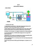
HYDRAULIC DESIGN 1
Design Equations Formulaes used in Hydraulic design are as under :A) Hazen williams Formula Friction loss in pipe is calculated using Hazen williams Formula V = 0.849 C R0.63 S0.54 Where, V = Velocity in m/sec C = Hazen Williams Constant = 100 R = Hydraulic Radius in m S = Hydraulic gradient B) Mannings Formula Friction loss in open channesl is calculated as under :V = (1/n) R2/3 S1/2 Where, V = Velocity in m/sec n = Mannings coefficient of roughness R = Hydraulic Radius in m S = Hydraulic gradient C) Weir Formula Discharge over weir is calculated by weir formula Q = 0.5445 Ce g b x H 1.5 Where, Q = Discharge in cum/sec Ce = Discharge coefficient = 0.864 b = Width of weir in m H = Depth of flow over weir in m D) Head loss through gates / valves E) Head loss at bends / entrance / exit losses
2
=
kV2 2g
(k = 0.50)
=
kV2 2g
(k = 0.50)
Design Considerations For 250 MLD Desired Output
Q(out)
Internal loss after considering recovery IL @ 3 % Q(in) = Q(out) + IL Raw water Input Working Hours
t Average Flow Rate (Normal) Q(avg)
For 300 MLD
250000.00 m3/day
300000
7500.00 m3/day
9000.00
257500.00 m /day 22.00 Hours/day
309000.00 22.00
11704.55 m3/Hour
14045.45
3
3
Overload flow for hydraulic design of inlet works
30.00 %
30.00
Overload flow for hydraulic design rest of the plant
25.00 %
25.00
Inlet Works Average Flow Rate
11704.55 m3/hour
14045.45
Inlet Works Average Flow Rate (Overload)
Q(OL) 30 % over nornmal flow 15215.91 m3/hour
18259.09
Inlet works Average Flow Rate (Normal)
Q(avg)
3.25 m3/Sec
3.90
Inlet works Average Flow Rate (Overload)
Q(OL) 30 % over nornmal flow
4.23 m3/Sec
5.07
Hydraulic Calculation a Inlet Chamber FSL Water Depth Invert Level b Inlet Channel Length Width Liquid Depth Hydraulic radius Cross Section Area Velocity
TWL d IL
225.000 M. R. L. 5.15 m 219.850 m
10 m 2.5 m 1.95 m 6.4 m 4.875 m 0.67 m/sec
Check for Velocity at Ultimate overload condition
1.04 m/sec
Check for Velocity at present overload condition
0.87 m/sec
Friction Loss Total Friction Loss Drop Provided FSL in the channel IL of Channel c Parshall Flume Approach Channel Width Design flow Max Design flow min Throat Width
0.0004883195 m/m 0.0048831953 m 0.2 m 224.800 m 222.850 m 2.50 m 5.07 m 3.25 m 1.5 m
Head at max. flow condition Q = 2.264WH3/2 Head at min. flow condition Headd Loss at Max Flow Head Loss at Min flow Level D/s of flume at max flow Level D/s of flume at Min flow
1.307 m 0.971 m 0.784 m 0.583 m 224.016 223.782
c Distribution Box No of Inlet No of Outlet HRT in the inlet box Weir length for distribution Maximum Flow through each weir Rise Over Weir Friction Loss between Channel and Distribution Box TWL in Distribution box top of weir TWL in outlet Box
1 No 6 No 60 Sec 5.00 m 0.845 m3/Sec 0.2 m 0.1 m 223.682 223.482 223.332
d Between Distribution Chamber & Flash Mixer Opening Size Velocity Through Opening Friction loss Provide TWL in Flash Mixer
1 m2 0.845 m/sec 0.018 0.02 223.312
e Flash Mixer to Clariflocculator Pipe size Flow Velocity Frction loss at entry Friction loss at exit length of pipe Area of cross section Hydraulic radius Friction Lossin pipe Add for minor losses Total Loss TWL in Clariflocculator Top of Weir TWL in Launder
f Friction Loss between Clariflocculator and filter
1m 0.845 m3/Sec 1.0769 m/sec 0.0296 m 0.0296 m 94.0000 m 0.785 m2 0.25 m 0.1467281 m 0.01467281 m 0.2205 m 223.091 M R. L 223.00 M R. L 222.85 M R. L
Channel Width Depth Area Hydraulic Radius Flow Velocity Friction Loss Length of channel Friction Loss Say TWL in Channel
1.6 m 1.4 m 2.24 m2 4.4 m 2.5 m3/Sec 1.13 m/sec 4.007751869E-05 m/m 160 0.006412403 M 0.01 m 222.84 M. R. L
f Friction Loss between Clariflocculator and filter Friction loss in channel between clf and filter inlet channel TWL Inlet Channel Losses in Filter TWL in Filter Outlet Channel
0.1 222.74 2m 220.74