![03 Flowatch HS Field Calibration Proceduretest RevB [PDF]](https://pdfs.asia/img/200x200/03-flowatch-hs-field-calibration-proceduretest-revb.jpg)
5 0 494 KB
MULTIPHASE FLOW METER FIELD CALIBRATION PROCEDURE Rev. B – page 1/7
FLOWATCH HS MULTI PHASE FLOW SKID MOUNTED FOR MOBILE WELL TEST SERVICE FIELD CALIBRATION PROCEDURE
B A
Review text and pictures First issue
01/09/2012 06/01/12
F. Lucchini F. Lucchini
REV.
DESCRIPTION
DATE
ISSUE BY
CHECKED
MULTIPHASE FLOW METER FIELD CALIBRATION PROCEDURE Rev. B – page 2/7
Index 1.
INTRODUCTION..............................................................................................................................3
2.
CONTACT INFORMATION................................................................................................................3
3.
GLOSSARY.......................................................................................................................................3
4.
PREPARATION OF THE SYSTEM/INSTALLATION..............................................................................4
5.
FUNCTIONAL TEST AND PREPARATION OF THE SYSTEM.................................................................5
6.
TEST SETUP.....................................................................................................................................5
7.
TEST EXECUTION.............................................................................................................................6
8.
MPFM SYSTEM CALIBRATION.........................................................................................................7
MULTIPHASE FLOW METER FIELD CALIBRATION PROCEDURE Rev. B – page 3/7
1. Introduction The scope of this document is to describe the phases and the requirements for the correct execution of the field calibration of the test Flowatch HS MPFM. All operation mentioned on this procedure, with particular reference to calibration, calculation setting adjustments, and all related setting intended to optimize MPFM performance shall be executed exclusively from specialized personnel of Pietro Fiorentini S.p.A. Pietro Fiorentini S.p.A. will not be responsible for any damage or malfunction of the MPFM system caused by incorrect use or operation.
2. Contact information For any further information or details, please contact: Pietro Fiorentini S.p.A. Via E.Fermi8/10 36057 Arcugnano (VI) Italy Telephone: +39 02 6961421 Telefax: +39 02 6880457 Web site: www.fiorentini.com Mr. Federico Lucchini Mr. Enrico Mella Email: [email protected]
3. Glossary GVF
Gas Volume Fraction
HW
Hardware
MPFM
Multiphase Flow Meter
PVT
Pressure Volume Temperature
SW
Software
WC
Water Cut
WLR
Water Liquid Ratio
GOR
Gas Oil Ratio
Rs
Residual gas in solution in oil at specific P & T
Bo
Oil Shrinkage factor/Oil volume factor at specific P & T
MULTIPHASE FLOW METER FIELD CALIBRATION PROCEDURE Rev. B – page 4/7
Z
Gas compressibility factor at specific P & T
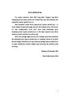
4. Preparation of the system/Installation The main requirement for the sensor installation is to be in vertical position with upwards flow direction. The installation of the MPFM on the skid ensure the vertical position/installation but it should be verified when preparing or unloading the skid at site that doe to ground condition irregularity the vertical installation condition get compromised. It is required also when connecting the temporary pipe work to the well head/manifold and consequently to the test separator too pay attention and observe the correct upward flow direction.
OUTLET
INLET
At the end of all mechanical installation, pipe connection and hammering activity a quick pressure test of the entire system performed with process gas from the well is a good test to verify the absence of any leak. It I strongly suggested to execute the test only after the execution of the empty pipe calibration and full water pipe gamma calibration. Please refer to document MT 169 EN RevF - On-site Installation Procedure for more information about installation of the MPFM.
MULTIPHASE FLOW METER FIELD CALIBRATION PROCEDURE Rev. B – page 5/7
5. Functional test and preparation of the system Before to start with the well test operation there are several verification that need to be performed in order to prepare the MPFM to work and guarantee the best performance in terms of results. If not already installed the Cs 137 gamma source contained must be installed now before the execution of the preliminary check. Only after the installation of the source is completed the source shutter can be rotated to open position ready for work. Execute after this operation the absence of any radioactivity leak around the source container, gamma detector and MPFM body. The following pre-test and static calibration should be executed: 1. Quick verification and functional test of all electronic equipment. 2. Verification and eventual adjustment if required of ZERO readings on the pressure and differential pressure transmitter under empty pipe condition. (This is also to correct for installation position of the skid). 3. Verification/log of the Permittivity readings from the capacitance sensor under empty pipe condition. Value logged should be used to adjust permittivity empty pipe reading to 1.00. 4. Log of the gamma count rate under empty sensor condition. This value stored on the calculation SW will be used for the mixture density calculation. It is very important to ensure that the sensor is completely empty and no liquid film is present on the internal wall of the sensor, this is why test described test as also the test on point 3. must be executed before to fill the sensor with any fluid. 5. Open the quick connection plug located in the top of the MPFM and fill the sensor with clean water, wait few minute to ensure that all air bubble are displaced by water in order to establish the full water pipe condition. Measure with the Anton Parr portable density meter the density of the water used to fill the sensor. Log on the MPFM SW the gamma count rated under this condition and insert the measured water density and temperature. This values stored on the SW will be used as calibration point to calculated the mixture density. 6. Drain the water and close the quick connection plug. Execute in case now leak test by using process gas from the well to ensure the absence of any leak. After all the checks has been executed with positive results the MPFM system can be considered ready to work and receive flow.
6. Test setup Prior to start the test it is important to verify that the selected well/s for the test execution are failing inside the MPFM operating envelope, the expected well production from historical data should be plotted on the operating envelope plot in order to verify that the operating condition are suitable to evaluate the performance of the MPFM. The well test duration need also to be agreed especially considering the well performance and behavior, we normally suggest a typical duration of 6 hours. Time period can be increased if the well production is unstable or intermittent but it can in can also be decreased if the well flowing condition are very stable. The required information needed to execute a good field calibration are: 1. Fluid properties of the production fluids, oil water and gas. Those information can be determined by sampling the 3 separate fluids from the sampling point available on the MPFM
MULTIPHASE FLOW METER FIELD CALIBRATION PROCEDURE Rev. B – page 6/7
skid and execute the appropriate measurements with the portable instruments available on the lab cabin directly at the well site. 2. Set of PVT data are also required to allow the final comparison of the results that need to be reported to STD condition. The results are normally reported and compared at that condition doe to the difference on operating condition between the MPFM and the test separator. In the case that the reference flow will be determined by using a calibrated static tank the availability of PVT information is very important doe to the fact that the tank is operating at atmospheric pressure, condition that is far different from the MPFM operating pressure and temperature. The PVT information are important on both cases to execute the first results comparison and to report the reference data afterward to MPFM operating condition in case of MPFM calibration is required. If the reference system is a typical portable test separator equipped with on board oil, water and gas measurements, the importance of PVT data set is less critical doe to the fact that the operating metering condition of the reference flow rates (test separator), are more similar to the MPFM operating condition. PVT data are also required to accurately calculate oil density reporting/converting the value measured at atmospheric pressure from the sample taken to operating pressure of the MPFM, the oil density change significantly with the operating pressure and an over estimation of this parameter may produce an underestimation of the liquid flow rate. In case of no availability of PVT data set, STD black oil calculation will be used. 3. Reference flow rate of liquid, oil water and gas plus the final average WC are required to execute eventual MPFM calibration if required. For a more detailed description about the fluid properties and PVT parameters needed refer to document MT 198 EN Rev B Fluid and PVT properties.
7. Test execution After the well has been diverted to the metering system, MPFM + Test separator + tank (if required), is important to wait for stabilization of both well performance and test separator. During the stabilization period sampling activity from the MPFM and analysis of the samples taken can start in order to prepare the set of fluid properties required. o o
From gas sample taken from gas pocket using Ranarex SG meter gas specific gravity will be determinate directly in the field. This value will be entered on the calculation SW. If the well is producing water, from the water pocket will be possible to recovery a separated water sample that will be used to measure density at a certain temperature. The same water sample will be used to measure water electrical conductivity used afterward to calculate water salinity by appropriate mathematical correlation. From water salinity will be possible to calculate the expected water density temperature gradient, used to report the measured water density at certain temperature (sample temperature), to MPFM operating temperature. In the case that the MPFM will work under CONDUCTIVITY mode will be required to entre on the calculation SW also the measured value of water conductivity and his related temperature. Adjustment of this value from sample temperature up to MPFM operating temperature will be automatically calculated from the calculation SW.
MULTIPHASE FLOW METER FIELD CALIBRATION PROCEDURE Rev. B – page 7/7
o
o
From a centrifuged oil sample measure the oil density and related temperature. This value will be entered on the calculation SW. In this case and especially if operating pressure is higher than 10 bar, it will be required to report oil density measured at atmospheric pressure to MPFM operating pressure. This can be done by using PVT experimental data contained on a PVT report or by using standard black oil formulas if PVT data are not available. All required PVT parameters: Bo, Rs and Z (gas compressibility factor) extrapolated from PVT report should be entered on the calculation SW in order to complete the well profile required for the system to calculate the measured flow rate at STD condition.
The official flow measurement start when the stabilization period if completed. It is good practice to take samples for oil, water, gas and liquid (water and oil mixture) to monitor if important variation on fluid properties happen. Liquid sample is used to monitor and verify the values of the WC. In case of high WC (MPFM operating under CONDUCTIVITY mode) is very important to measure and monitor the eventual variation of the water electrical conductivity. It is suggested to take at least one sample per hour during the all test period. If important variation in any of the mentioned fluid properties will be noticed it will be important to update the values stored on the calculation SW in order to optimize the final results. During the entire duration of the test RAW data file from the sensor will be logged and stored in order to allow at the end of the test the reprocessing activity and the validation of the test results. Only the validated results reported at STD condition from both the systems, MPFM and test separator, will be compared in order to verify the relative deviation for: o o o
Liquid flow rate Gas flow rate WC
The above mentioned process will be executed for all the wells intended to be tested/used as performance comparison/calibration of the MPFM. Bigger will be the number of test executed for the calibration, covering more than one flowing condition, more exhaustive will be the calibration process.
8. MPFM System calibration If the reported deviation calculated from the well test/s will fail outside the acceptance criteria for one or more variables and/or wells it will be necessary to adjust one or more calculation parameters on the calculation SW. A data reprocessing process using proprietary Pietro Fiorentini SW, will be used to determine which parameters of the calculation models need to be adjusted and the consequent verification that the adjustments done will produce the expected performance improvement. At the end of the process the new calculation settings will be uploaded on the MPFM flow computer and it will be possible in case to execute a new well test to validate and verify that the new calculation set gave the expected improvement.