![Overhaul Manual - Direct Drive Engine PDF [PDF]](https://pdfs.asia/img/200x200/overhaul-manual-direct-drive-engine-pdf.jpg)
13 0 10 MB
Overhaul Manual Direct Drive Engine
Approved by F.A.A. Sixth Printing December 1974
LYCOIIIIIIIIG A Textron Company
Part No. 60294-7
652 Oliver Street Williamsport, PA 17701
U.S.A.
SECTION 7 OVERHAUL MANUAL LYCOMING AIRCRAFT ENGINES CRANKCASE, CRANKSHAFT AND RECIPROCATING PARTS DIRECT DRIVE
TECHNICAL PUBLICATION REVISION REVISION NO.
PUBLICATION
PUBLICATION NO.
PUBLICATION DATE
60294714
Direct Drive Overhaul Manual
602947
December 1974
The page(s) in this revision replace, add to, or delete current pages of the publication indicated above. PREVIOUS REVISION CURRENT REVISION April 1966 53, 56; 85 July 1967 58; 61 thru 618, 623, deleted pages 625 thru 632 April 1968 42 thru 48 December 1968 Section 11 replaced Special Tool Catalog January 1970 i, ii, deleted pages iv and v; 11, 12, deleted pages 13; 21 thru 26, deleted pages 27 thru 212; 31 thru 35; 41; 91, 92, 94, deleted page 97; 101 thru 1036, deleted pages 1037 thru 1047 January 1971 i, ii; 619 thru 624; 71 thru 719; 93, 95, 96 May 1972 Added page 27; 31, 35; 51 thru 511, deleted pages 512, 513, 514; 61, 617, 618, 622, 623; 81 thru 86, deleted pages 87, 88; 93 October 1973 i, ii, iii; 11; 33, 34, 35; 41, 43 thru 48; 51, 55, 56, 57, 59, 510; 62, 67, 610, 611, 612, 613, 617, 620, 621, 622, 623; 74, 716, 717, 718, 719; 91, 92 February 1992 i June 1993 710, added pages 710A, 710B, 710C, 710D, 712, 712A/B June 1996 i June 1999 74 June 2002 710B January 2007 i, ii, iii, added page iv; 11, 12, 13; 74, added pages 74A, 74B; 75, 716, added pages 716A, 716B September 2007 715, 716, 716A, 716B July 2008 715, 716A October 2010 715, 714
July 2011 710D
©2011 by Avco Corporation. All Rights Reserved
Lycoming Engines is a division of Avco Corporation
710D
Revised July 2011
OVERHAUL MANUAL - LYCOMING DIRECT DRIVE AIRCRAFT ENGINES
TO THE OWNER OF THIS MANUAL IN ADDITION TO THIS MANUAL AND SUBSEQUENT REVISIONS, ADDITIONAL OVERHAUL AND REPAIR INFORMATION IS PUBLISHED IN THE FORM OF SERVICE BULLETINS AND SERVICE INSTRUCTIONS. THE INFORMATION CONTAINED IN THESE SERVICE BULLETINS AND SERVICE INSTRUCTIONS IS AN INTEGRAL PART OF, AND IS TO BE USED IN CONJUNCTION WITH, THE INFORMATION CONTAINED IN THIS OVERHAUL MANUAL. THIS OVERHAUL MANUAL, THE ENGINE OPERATOR'S MANUAL, AND ALL APPLICABLE SERVICE BULLETINS AND INSTRUCTIONS ARE ISSUED IN COMPLIANCE WITH F.A.R 21.50, AND SHALL BE USED BY MAINTENANCE PERSONNEL WHEN PERFORMING ACTIONS SPECIFIED IN F.A.R 43.13. For a period of three (3) years new and revised pages for this manual will be furnished to owners who fill lout the registration card and return it to Lycoming. Registered owners of this manual will be notified of any changes in revision policy or cost of revisions. Service Bulletins, Service Instructions and Service Letters are available from all Lycoming Distributors or from the factory by SUbscription. Consult the latest revision to Lycoming Service Letter No. Ll14. Lycoming also publishes an Index of Service Bulletins, Instructions and Letters that lists all Bulletins, Instructions and Letters in alphabetical order by title and top as well as a list of Bulletins, Instructions and Letters applicable to each engine series. Consult the Service Publication Section of the latest revision to Service Letter No. L114 for the current part number of the index.
I
SPECIAL NOTE The illustrations, pictures and drawings shown in this publication are typical of the suhject matter they portray; in no instance are they to be interpreted as examples of (lll)' specific engine, equipment or part thereof
Revised January 2007
OVERHAUL MANUAL - LYCOMING DIRECT DRIVE AIRCRAFT ENGINES TABLE OF CONTENTS SECTION
PAGE INTRODUCTION ........................................ 1-1
2
SECTION 4
GENERAL DESCRIPTION
GENERAL OVERHAUL PROCEDURES General .................................................. 3-1 Cleaning Degreasing ..................................... 3-1 Removal of Hard Carbon ............... 3-1 Inspection General ........................................... 3-2 Bearing Surfaces ............................ 3-2 Gears .............................................. 3-2 Corrosion ....................................... 3-2 Screwed Fittings ............................ 3-2 Magnetic ........................................ 3-2 Corrosion Prevention ..................... 3-3 Repair and Replacement Damaged Parts ............................... 3-3 Painted Parts .................................. 3-3 Replacement of Studs .................... 3-3 Corrosion Prevention ..................... 3-3 Reassembly Corrosion Prevention ..................... 3-3 Pre lubrication of Parts .................... 3-3 Oilite Bushings .............................. 3-4 Pitch Alignment and Backlash in Bevel Gear Assemblies ........... 3-4 Table of Limits ............................... 3-5 Oil Seals and Gaskets ..................... 3-5 Arbitrary Replacement of Parts ...... 3-5 I Fuel Supply Lines .......................... 3-5
4
IGNITION SYSTEM General .................................................. 4-1 Magnetos Impulse Coupling ........................... 4-1 Retard Breaker .............................. .4-1
II
IGNITION SYSTEM (CONT.) Engine Firing Order. ............................. .4-1 Ignition Harnesses ................................ .4-1 Spark Plugs ............................................ 4-1 Removal and Disassembly Ignition Harness ............................ .4-1 Magnetos ........................................ 4-1 Inspection Ignition Harness ............................ .4-3 Magnetos ........................................ 4-3 Repair and Replacement Ignition Harness ............................ .4-3 Magnetos ........................................ 4-4 Reassembly Magnetos ....................................... .4-5 Installation Magnetos ....................................... .4-5 Timing Magneto to Engine ........... .4-5 Ignition Harness ............................ .4-8
Cylinders ............................................... 2-1 Valve Operating Mechanism ................. 2-1 Hydraulic Tappets ................................. 2-2 Crankcase .............................................. 2-3 Crankshaft ............................................. 2-3 Crankshaft Counterweights ................... 2-3 Accessory Housing ............................... 2-3 Connecting Rods ................................... 2-3 Pistons ................................................... 2-3 Lubrication System ............................... 2-3 Cooling System ..................................... 2-4 Induction System Carbureted ...................................... 2-6 Fuel Injected .................................. 2-6 Turbocharger Controls .......................... 2-6 Ignition System ..................................... 2-6 3
PAGE
5
ACCESSORY HOUSING Disassembly .......................................... 5-1
I Cleaning ................................................ 5-5 Inspection .............................................. 5-5 Repair and Replacement.. ...................... 5-5 Reassembly ............................................ 5-5 Dual Drives ........................................... 5-9 Fuel Pumps .......................................... 5-10 Oil Filter .............................................. 5-10 Oil Cooler Bypass Valve ..................... 5-10 6
CYLINDERS, PISTONS AND VALVE TRAIN General .................................................. 6-1 Removal from Engine ........................... 6-1 Disassembly .......................................... 6-7 Cleaning ................................................ 6-7 Inspection .............................................. 6-7 Cylinders ........................................ 6-8 Pistons ............................................ 6-9 Valve Rockers .............................. 6-10 Push Rods ..................................... 6-1 0 Valves ........................................... 6-10 Hydraulic Tappets ........................ 6-11 Valve Springs ............................... 6-13 Modifications ...................................... 6-13 Repair and Replacements .................... 6-13 Spark Plug Inserts ........................ 6-14 Valve Seats ................................... 6-15 Valve Guides ................................ 6-17 Valve Rocker Thrust Washers ...... 6-17 Valve Rocker Shaft Bushings ....... 6-18 Plain Steel Cylinder Barrels ......... 6-19 Revised January 2007
OVERHAUL MANUAL - LYCOMING DIRECT DRIVE AIRCRAFT ENGINES TABLE OF CONTENTS (CONT.) PAGE
SECTION 6
CYLINDER, PISTONS AND VALVE TRAIN (CONT.)
SECTION 7
Nitrided Cylinder Barrels ............. 6-20 Chrome Plated Cylinder Barrels .. 6-20 Valve Repair ................................ 6-20 Warped Exhaust Flanges ............. 6-20 Reassembly Assembly ..................................... 6-20 Assembly of Cylinders ................. 6-21 Installation of Pistons ................... 6-21 Installation of Cylinders ............... 6-21 Cylinder Head Fin Stabilizers ...... 6-23 Cylinder Painting ......................... 6-24 Intercylinder Baffles .................... 6-24 7
Revised January 2007
CRANKCASE, CRANKSHAFT AND RECIPROCATING PARTS (CONT.) Oil Seal Surface ...................... 7-8 Counterweight Bushings ......... 7-9 Counterweight Bushings .............. 7-10 Connecting Rod Bushings ............ 7-10 Crankshaft and Gear Assy ............ 7-lO Starter Ring Gear ...................... 7-1 OC Crankcase .................................. 7-1 OC Oil Relief Valve Sleeve ................ 7-11 Oil Pressure ReliefValve ............. 7-12 Crankcase ..................................... 7 -12 Crankshaft Idle Gear Shaft Recess ................................... 7-12 Reassembly Crankshaft Sludge Tubes ......................... 7 -12 Expansion Plug ..................... 7-12 Propeller Flange Bushings .... 7-12 Gear. ...................................... 7-12 I Counterweight Assy ....... 7-12A1B Connecting Rods .......................... 7 -14 Camshaft ...................................... 7 -14 Crankcase ..................................... 7 -15 Propeller Governor Drive ............. 7-15 Crankshaft Oil Seal ...................... 7-17 Hydro Control Valve .................... 7-17 Generator or Alternator Drive Belt... ..................................... 7-17 Crankshaft Idler Gears ................. 7 -18
I
CRANKCASE, CRANKSHAFT AND RECIPROCATING PARTS Removal of Accessories ........................ 7-1 Disassembly Starter Ring Gear Support .............. 7-1 Prop. Governor Oil Line ................ 7-1 Crankcase ....................................... 7-1 Crankshaft ...................................... 7-1 Counterweights ....................... 7-3 Sludge Tubes .......................... 7-3 Cleaning General ........................................... 7 -3 Piston Cooling Oil Jets .................. 7-3 Inspection Bearings ......................................... 7-4 Crankcase Visual ...................................... 7-4 Dimensional ............................ 7-4 Crankshaft Visual ...................................... 7-4 Magnetic Particle .................... 7-4 "PID" Stamped .................... 7-4A Dimensional ......................... 7-4A Camshaft Visual ................................... 7-4B Dimensional ......................... 7-4B Main Bearing Clearance ............. 7-4B Connecting Rods Dimensional ............................ 7-6 Parallelism Check ................... 7-6 Squareness Check ................... 7-6 Crankshaft Counterweight Bushings ................................. 7-6 Piston Cooling Oil Jets .................. 7-6 Repair and Replacement Crankshaft Bearing Surfaces ..................... 7-7 Straightening Flange ............... 7-7
PAGE
8
OIL SUMP AND FUEL INDUCTION General ................................................ 8-1 Disassembly Intake Pipes .................................... 8-1 Carburetor or Fuel Injector.. ........... 8-1 Induction Housing .......................... 8-1 Oil Sump ........................................ 8-1 Cleaning Oil Sump ........................................ 8-1 Carburetor ...................................... 8-1 Fuel Injector ................................... 8-1 Injector Nozzles ............................. 8-1 Inspection Oil Sump ........................................ 8-1 Carburetor ...................................... 8-2 Fuel Injector ................................... 8-2 Nozzle Assembly ........................... 8-2 Repair and Replacement Intake Pipes .................................... 8-3 Carburetor ...................................... 8-3 Fuel Injector ................................... 8-3 III
OVERHAUL MANUAL - LYCOMING DIRECT DRIVE AIRCRAFT ENGINES TABLE OF CONTENTS (CONT.) SECTION 8
PAGE OIL SUMP AND FUEL INDUCTION (CONT.)
SECTION 9
TEST PROCEDURES General ................................................ 9-1 Test Limits ............................................ 9-2 Turbocharged Engines .......................... 9-3
IV
TEST PROCEDURES (CONT.) Pressure Carburetors .............................. 9-3 Run-In Procedure .................................. 9-3 Run-In Schedule .................................... 9-3 Oil Consumption Run ............................ 9-4 Oil Pressure Relief Valve ...................... 9-4 Idle Speed and Mixture Adjustment ...... 9-4 Preservation and Storage (Engine) ........ 9-5 Preservation - Run ................................ 9-6 Preservation and Storage Carburetors and Fuel Injectors ....... 9-6
Reassembly Induction Housing .......................... 8-4 Flow Dividers ................................ 8-6 Intake Pipes .................................... 8-6 Nozzle Assembly ........................... 8-6 9
PAGE
10
TABLE OF LIMITS
Added January 2007
OVERHAUL MANUAL - LYCOMING AIRCRAFT ENGINES DIRECT DRIVE
SECTION 1 INTRODUCTION
SECTION 1 INTRODUCTION I
I-I. This manual contains the necessary information for the overhaul of the Lycoming horizontally installed direct drive engines. Unless otherwise noted, all information and data in the manual will apply equally to all models; those portions of the text applying to anyone particular model or series will be so identified. 1-2. The main portion of the text is divided into sections corresponding to the basic engine components. Additional sections are provided for general description, general overhaul, cleaning, inspection procedures, preservation and storage information, along with other items of a non-specific nature. 1-3. The tools required for overhauling the engines (excluding the ordinary mechanic's tools found in most overhaul shops) are listed in SSP-384, the Special Service Tools publication. Inspection gages are also listed in the same publication. Any special information required concerning tools may be obtained by writing to the Service Department, Lycoming Engines, 652 Oliver Street, Williamsport, Pennsylvania, 17701. When requesting information concerning any of these tools, refer to the tool by name and part number and not merely by name.
I
1-4. Parts Catalogs for specific models, may be ordered from the department listed in paragraph 1-3. Because this manual covers the entire series of engines, it is almost impossible to call out attaching parts for specific models.
I
Therefore, it is required that the parts catalogs be used with the manual, when reassembling the engine.
I I
1-5. The following procedure must be followed if warranty parts are to be returned to the factory. You may obtain from, but preferably have your distributor complete, the applicable warranty form. This form must include the engine models and serial numbers, number of hours in service, the reason for the parts being returned and any other pertinent facts concerning the parts.
I 1-6.
In this manual all references to locations of various components will be designated when viewing the engine from the rear (anti-propeller). The propeller end is considered the front and the accessory drive end the rear. The oil sump is considered the bottom. Cylinders are numbered from front to rear with odd numbered cylinders on the right side. (The most forward cylinder is always designated the Number 1 cylinder.)
I
1-7. The direction of rotation of the crankshaft as viewed from the rear, is clockwise on all models with the following exception. The direction of rotation of the crankshaft, as viewed from the rear is counterclockwise on all models with I the letter L in the model prefix. (Example - LTIO-540-J.) All references to direction of rotation of the various accessory drives are viewed facing the accessory drive mounting pad.
NOTE
In addition to this manual and subsequent revisions, additional overhaul and repair information is published in the form of Service Bulletins and Service Instructions. The information contained in these Service Bulletins and Service Instructions is an integral part of, and is to be used in conjunction with, the il~rormation contained in this overhaul manual. When received, these publications should be inserted in the rear of this manual or maintained in a separate file for ready reference.
Revised January 2007
1-1
SECTION 1 INTRODUCTION
OVERHAUL MANUAL - LYCOMING AIRCRAFT ENGINES DIRECT DRIVE
Figure 1-1. Typical 4 Cylinder Engine
Figure 1-2. Typica16 Cylinder Engine 1-2
Revised January 2007
OVERHAUL MANUAL - LYCOMING AIRCRAFT ENGINES DIRECT DRIVE
SECTION 1 INTRODUCTION
Figure 1-3. Typical 8 Cylinder Engine
Added January 2007
1-3
OVERHAUL MANUAL·
LYCOMING DIRECT DRIVE AIRCRAFT ENGINES
Section 2 General Description
SECTION 2. GENERAL DESCRIPTION 2-1. The engines covered in this manual are direct drive, four, six and eight cylinder, horizontally opposed, air cooled models.
2-4. Avco Lycoming incorporates a color code painted on cylinder heads designating differences in the cylinder barrels and spark plug lengths. It is essential that personnel be familiar with this code as described in the latest edition of Service Instruction No. 1181.
2-2. CYLINDERS. The cylinders are of air cooled construction with the major parts, head and barrel, screwed and shrunk together. The heads are made from an aluminum alloy casting with a fully machined combustion chamber. Valve guides and valve seats are shrunk into machined recesses in the head. Rocker shaft bearing supports are cast integrally with the head along with the housings to form the rocker boxes for both exhaust and intake valve rockers.
2- 5. Damage will result with the use of incorrect piston rings or spark plug lengths. The latest edition of Service Instruction No. 1037 lists the approved piston, piston ring and cylinder assemblies for all models while the latest edition of Service Instruction No. 1042 lists the approved spark plugs. Consult these publications for correct application to your particular installation.
2- 3. The cylinder barrels are machined from a chrome nickel molybdenum steel forging with deep integral cooling fins. The interior of the barrels are ground and honed to a specified finish.
2- 6. VALVE OPERATING MEC HANISM. A conventional camshaft is located above and parallelto the crankshaft. The camshaft actuates tappets which operate the
,
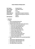
Description of Engine Model Code Example:
TID
541
I
L-
PREFIX Lefthand Engine Rotation
\
DISPLACEMENT
000*
Cubic in.
T - Turbocharged
EIB4D
E-
SUFFIX Power Section a Rating
V- Vertical Helicopter
I - Nose Section B - Accessory Section
H-Horizontal Helicopter
4 -Counterweight Application
A- Aerobatic
o-Dual Magneto
* Note: (DO/) '~"lndicates integral
I - Fuel Injected
accessory drive
G- Geared Nose Section
S - Supercharged
Subsequent changes to Models are reflected in this Section--~
o-Opposed Cylinder Figure 2-1. Description of Engine Model Code Revised January, 1970
2-1
Section 2 Generol Description
OVERHAUL MANUAL.
LYCOMING DIRECT DRIVE AIRCRAFT ENGINES
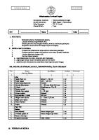
valves through push rods and valve rockers. The valve rockers are supported on full floating steel shafts. The valve springs bear against hardened steel seats and are retained on the valve stems by means of split keys. A rotator cap is employed on sodium cooled exhaust valves. NOTE Hydraulic tappets, which automatically keep the valve clearance at zero, are used on all subject engines except the 0-235-C and 0- 290- D series engines. These series employ solid tappets and the proper valve clearance is obtained with the aid of an adjusting screw located in the valve rocker. Figure 2-2. Hydraulic Tappet Assembly 2-7. HYDRAULIC TAPPETS. When the valve is closed, the face of the cam follower is on the base circle or back of the cam. The light plunger spring lifts the hydraulic plunger so that its outer end contacts the push rod, exerting a light pressure against it, thus eliminating any clearance in the valve linkage. As the
plunger moves outward, the ball check valve moves off its seat. Oil from the supply chamber, which is directly connected to the engine lubrication system, flows in and fills the pressure chamber. As the camshaft rotates, the cam pushes the cam follower and the hy-
SPLASH OIL TO ROCKER ARMS ,VALVE STEMS ,ETC. ---~
j ORAIN OIL TO SUMP THRU OIL ORAIN TUBES
TAPPETS LEFT BANK CRANKCASE OIL HEADER-LEFT
SPLASH OIL TO PISTONS PISTON PINS,CAMS,ETC.
SPLASH OIL TO PISTONS PISTON PINS,CAMS,ETC.
CAMSHAFT BEARING NO. I NO.1 MAIN BEARING
( I I
I
~PROP GOVERNOR OIL
VACUUM PUMP
I I SPLASH OIL TO ROCKER I ARMS, VALVE STEMS,
Q D , I
I
GRAVITY OIL THRU SHROUO TUBES
: DRAIN OIL TO SUMP THRU OIL DRAIN TUBES " h
,
PRESSURE
'"
1,' I OIL RELIEF VALVE DRAIN OIL TO SUMP
II II II
:l=-~OP-=-~h l~~~~!!.f=
VACUUM PUMP DRIVE
TAPPETS RIGHT BANK
I
OIL COOLER BY-PASS VALVE
OIL PUMP
SUCTION SCREEN OIL SUMP
Figure 2-3. Lubrication Diagram - 4 Cylinder Engines 2-2
Revised January, 1970
OVERHAUL MANUAL-
LYCOMING DIRECT DRIVE AIRCRAFT ENGINES
draulic lifter cylinder outward. This action forces the ball check valve onto its seat; thus, the body of oil trapped in the pressure chamber acts as a cushion. During the interval when the engine valve is off its seat, a predetermined leakage occurs between plunger and cylinder bore which compensates for any expansion or contraction occurring in the valve train. Immediately after the engine valve closes, the amount of oil required to fill the pressure chamber flows in from the supply chamber, thereby preparing for another cycle of operation.
Section 2 Generol Description
2-10. CRANKSHAFT COUNTERWEIGHTS. A system of dynamic counterweights, to eliminate torsional vibration, is provided on all six and eight cylinder and some four cylinder engines. Consult the latest edition of Service Instruction No. 1012 for proper combination and location on the crankshaft. 2-11. ACCESSORY HOUSING. The accessory housing is machined from an aluminum alloy casting and is fastened to the rear of the crankcase and the top of the oil sump. Accessories are mounted on machined pads located on the rear of the housing.
2-8. CRANKCASE. The crankcase assembly consists of two reinforced aluminum alloy castings divided at the centerline of the engine and fastened together by a series of studs, bolts and nuts. The mating surfaces of the two castings are joined without the use of a gasket, and the main bearing bores are machined for the use of precision type main bearing inserts. The crankcase forms the bearings for the camshaft.
2-12. CONNECTING RODS. The connecting rods are made in the form of "H" sections from alloy steel forgings. They have replaceable bearing inserts in the crankshaft ends and split type bronze bushings in the piston ends. The bearing caps on the crankshaft end of the rods are retained by two bolts through each cap secured by a crimp nut.
2-9. CRANKSHAFT. The crankshaft is made from a chrome nickel molybdenum steel forging and all journal surfaces are nitrided. Earlier models were provided with sludge tubes at each crankpin. These sludge tubes are not incorporated in later models. This is not to imply that sludge tubes may be removed and not replaced in crankshafts originally manufactured with sludge tubes. These tubes must be removed and replaced at overhaul.
2-13. PISTONS. The pistons are machined from an aluminum alloy forging. The piston pin is of the full floating type with a plug located in each end of the pin. Consult Service Instruction No. 1037 for proper piston and ring combinations. 2-14. LUBRICATION SYSTEM. All subject engines, with the exception of the AIO series, employ a fall
SPLASH OIL TO ROCKER ARMS, VALVE STEMS, ETC,
I DRAIN OIL TO SUMP THRU OIL DRAIN TUBES
SPLASH OIL TO
PISTONS,PISTON PINS, CAMS, ETC --'----H---+-CRANKPIN
-H---+---r PRESSURE OIL
TO PROP
SPLASH OIL TO TACH. DRIVE
TAPPETS RIGHT BANK ~
SPLASH OIL TO ROCKER
ARMS VALVE STEMS, ETC.---i
AND DRI'v'En
ROCKER ARM
1
DRAIN'OI~ TO SUMP
\
Y
BUSHINGS
~h-~-'-----"
THRU OIL DRAIN TUBES
, - - - - - - - j H y D . PUMP AND DRIVE
Q'
"AN"FUEL PUMP
PUSH RODS
PRES. SCREEN
VACUUM PUMP AND DRIVE
I
OIL RELIEF VALVE
GRAVITY OIL THRU SHROUD TUBES OIL PUMP
:;-!.:-_-_-_-_-L'I] SUCTION SCREEN
I~::::==::=~i
OIL COOLER
OIL SUMP
Figure 2-4. Lubrication Diagram - 6 Cylinder Engines Revised January, 1970
2-3
Section 2 General Description
LYCOMING DIRECT DRIVE AIRCRAFT ENGINES
OVERHAUL MANUAL-
Oil Filler a Dipstick - - ' -
Far Side _ _ Oil Scavenge Line -_.../ On Engine
oJ
Breather Une Oil Return
Figure 2- 5. Schematic Oil System - Alo- 320 and AlO- 360 pressure wet sump lubrication system. See figures 2-3 and 2-4 for diagrams of typical four and six cylinder lubrication systems. See figure 2- 5 for schematic of the oil system of the AlO series.
2-15. COOLING SYSTE M. These engines are designed to be cooled by air pressure built up on one side of the cylinder and discharged, with accompanying pressure drop, through the cylinder fins.
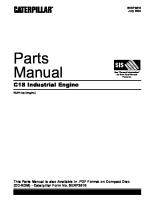
Vacuum Pump Drive Gear No. of teeth 10 Ratio 130: I
Camshaft Gear a Tachometer Drive No. of teeth 26 Ratio .50: I Crankshaft Idler Gear No. of teeth 26
..-----Magneto Gear No. of teeth 13 Ratio 1:1 Cam
Magneto Gear No. of teeth 13 Ratio 1:1 Crankshaft Gear -----'' No. of tellth 13 Crankshaft Idler Gear No. of teeth 26
Figure 2-6. Gear Train Diagram - 0-235, 0-290-D and 0-290-D2 Series 2-4
Revised January, 1970
OVERHAUL MANUAL-
LYCOMING DIRECT DRIVE AIRCRAFT ENGINES
Section 2 General Description
Camshaft Gear So ------,-----1 Diaphragm Type Ratio .50'1 Propller Gov. Drive Gear Ratio .8661I
Figure 2-7. Gear Train Diagram - Typical 4 Cylinder Engine Governor Idler Gear ------,
Fuel Pump Idler Gear----l
Hydraulic Pump Driven Gear Ratio I. 385 :I
Fuel Pump Drive An Type Ratio 1:1 Timing marks are shown when It of No.1 cronkpin is at T. C.
Figur.e 2-8. Gear Train Diagram - Typical 6 Cylinder Engine Revised January, 1970
2-5
Section 2 Generol Description
OVERHAUL MANUAL·
LYCOMING DIRECT DRIVE AIRCRAFT ENGINES
2-16. INDUCTION SYSTEM (Engines Employing Carburetors). Subject engines may be equipped with either a float type or pressure type carburetor. Particularly good distribution of the fuel-air mixture to each cylinder is obtained through the center zone induction system, which is integral with the oil sump and is submerged in oil, insuring a more uniform vaporization of fuel and aiding in cooling the oilin the sump. From the riser the fuel-air mixture is distributed to each cylinder by individual intake pipes. 2-17. INDUCTION SYSTEM (Engines Employing Fuel Injectors). The fuel injection system schedules fuel flow in proportion to airflow and vaporization takes place at the intake ports. In addition, on the TIO- 360 and TIO- 540 series, a turbocharger furnished as an integral part of the engine provides constant air density to the fuel injector inlet from sea level to critical altitude. 2-18. TURBOCHARGER CONTROLS. The turbocharger control system consists of three components, namely, the exhaust bypass valve (waste gate), the density controller and the differential pressure controller.
The position of the exhaust bypass valve establishes the amount of supercharging delivered to the engine. Increasing oil pressure closes the valve and increases power. Decreasing oil pressure opens the valve and decreases power. The density controller regulates the oil pressure to the bypass valve while the engine is operating at wide open throttle and limits manifold pressure below critical altitude. The differential pressure controller regulates the oil pressure to the bypass valve while the engine is operating at part throttle settings below critical altitude. 2-19. IGNITION SYSTEM. Dual ignition is furnished for all subject engines. Several combinations of magnetos and various ignition harnesses are employed. Consult the applicable parts catalog for your particular installation. Consult the latest edition of Service Instruction No. 1042 for a list of Avco Lycoming approved spark plugs.
Prop Governor Idler Gear 19 teeth (I 5833 PD) 15 teeth (1.250 PD.)
/ " - - - Camshaft Gov. Drive Gear No. of teeth 34 ~--Vacuum
Pump Drive Gear No. of teeth 10 Ratio 1.30:1
Prop. Governor Drive Gear No. of teeth 15 Ratio .895: I
Crankshaft Idler Gear 26 teeth (325 PD,) 19 teeth (2.4375 PD)
- - - - - - - - - - - - Camshaft Gear S. Tachometer Drive No. of teeth 26 Ratio ,50:1
Magneto Gear - - -______ 700 Series Magneto Ratio .500: I 1200 Series Magneto Ratio 1:1
, r - - - - - - - - - - Crankshaft Gear
No. of teeth 13 Magneto Gear 700 Series Magneto Ratio ,500:1 1200 Series Magneto Ratio I: I Crankshaft Idler Gear 26 teeth (3,25 PD) 19 teeth (2.4375 PO.) 27teeth (225 PD) (With Pneumatic Drive) Hydraulic Pump Drive Gear No. of teeth 10 Ratio 130: I
Fuel Pump Idler Gear - - - - - - - - - ; 19 teeth (2,375 PD,)
Fuel Pump Drive Gear --------- """
Hyd. Pump Drive Adapter Oil Seal Fuel Pump Gasket Dual Magneto Driving Impeller Driven Impeller Magneto Gear Accy. Driven Gear Gasket Thermostatic Valve Washer
o < '";III
:r
:..
....c: ~
:..
z
c: :.. .... I
.... o
-< n
18
~
Z
Q til
:iii n '"
®
-4
til
:.
·0