![Well Intervention Catalog [PDF]](https://pdfs.asia/img/200x200/well-intervention-catalog.jpg)
9 0 16 MB
Well Intervention Catalog Volumes 1, 2 & 3
Schlumberger 3750 Briarpark Drive Houston, Texas 77042 www.slb.com Copyright © 2015 Schlumberger. All rights reserved. No part of this book may be reproduced, stored in a retrieval system, or transcribed in any form or by any means, electronic or mechanical, including photocopying and recording, without the prior written permission of the publisher. While the information presented herein is believed to be accurate, it is provided “as is” without express or implied warranty. Specifications are current at the time of printing. Temperature ratings are for the internal tool components.
An asterisk (*) is used throughout this document to denote a mark of Schlumberger. Other company, product, and service names are the properties of their respective owners.
Previous | Main Menu | Search | Next
Contents - click on Volume to access Volume 1: Products and Services Products and Services Volume 1
Well Intervention Catalog Volume 1: Products and Services
Volume 2: Case Studies Case Studies Volume 2
Well Intervention Catalog Volume 2: Case Studies
Volume 3: Matrix Stimulation Matrix Stimulation Volume 3
Well Intervention Catalog Volume 3: Matrix Stimulation
Well Intervention Catalog
■
Contents
Previous | Copyright Page | Search | Next
Products and Services Volume 1
Schlumberger 3750 Briarpark Drive Houston, Texas 77042 www.slb.com Copyright © 2015 Schlumberger. All rights reserved. No part of this book may be reproduced, stored in a retrieval system, or transcribed in any form or by any means, electronic or mechanical, including photocopying and recording, without the prior written permission of the publisher. While the information presented herein is believed to be accurate, it is provided “as is” without express or implied warranty. Specifications are current at the time of printing. Temperature ratings are for the internal tool components. 14-WI-0013 An asterisk (*) is used throughout this document to denote a mark of Schlumberger. Other company, product, and service names are the properties of their respective owners.
Previous | Main Menu | Contents | Search | Next
Click on entry or page number for access.
Contents Coiled Tubing . . . . . . . . . . . . . . . . . . . . . . . . . . . . . . . . . . . . . . . . . . . . . . . . . . . . . . . . . . . . . . . . . . . . . . . . . . . . . . . . . . . . . . . . . . . . . . . . . . . . . . . . . . . . . . . . . . . . . . . . . . 1 Coiled Tubing Surface Equipment . . . . . . . . . . . . . . . . . . . . . . . . . . . . . . . . . . . . . . . . . . . . . . . . . . . . . . . . . . . . . . . . . . . . . . . . . . . . . . . . . . . . . . . . . . . . . . 3 CT TComp . . . . . . . . . . . . . . . . . . . . . . . . . . . . . . . . . . . . . . . . . . . . . . . . . . . . . . . . . . . . . . . . . . . . . . . . . . . . . . . . . . . . . . . . . . . . . . . . . . . . . . . . . . . . . 5 CT EXPRESS . . . . . . . . . . . . . . . . . . . . . . . . . . . . . . . . . . . . . . . . . . . . . . . . . . . . . . . . . . . . . . . . . . . . . . . . . . . . . . . . . . . . . . . . . . . . . . . . . . . . . . . . . . . 7 X-11 . . . . . . . . . . . . . . . . . . . . . . . . . . . . . . . . . . . . . . . . . . . . . . . . . . . . . . . . . . . . . . . . . . . . . . . . . . . . . . . . . . . . . . . . . . . . . . . . . . . . . . . . . . . . . . . . . . 9 CT SEAS . . . . . . . . . . . . . . . . . . . . . . . . . . . . . . . . . . . . . . . . . . . . . . . . . . . . . . . . . . . . . . . . . . . . . . . . . . . . . . . . . . . . . . . . . . . . . . . . . . . . . . . . . . . . . . 13 Catenary Intervention . . . . . . . . . . . . . . . . . . . . . . . . . . . . . . . . . . . . . . . . . . . . . . . . . . . . . . . . . . . . . . . . . . . . . . . . . . . . . . . . . . . . . . . . . . . . . . . . . . . 16 ACTive Portfolio ACTive . . . . . . . . . . . . . . . . . . . . . . . . . . . . . . . . . . . . . . . . . . . . . . . . . . . . . . . . . . . . . . . . . . . . . . . . . . . . . . . . . . . . . . . . . . . . . . . . . . . . . . . . . . . . . . . . 21 ACTive GR . . . . . . . . . . . . . . . . . . . . . . . . . . . . . . . . . . . . . . . . . . . . . . . . . . . . . . . . . . . . . . . . . . . . . . . . . . . . . . . . . . . . . . . . . . . . . . . . . . . . . . . . . . . . 23 ACTive TC . . . . . . . . . . . . . . . . . . . . . . . . . . . . . . . . . . . . . . . . . . . . . . . . . . . . . . . . . . . . . . . . . . . . . . . . . . . . . . . . . . . . . . . . . . . . . . . . . . . . . . . . . . . . . 25 ACTive PS . . . . . . . . . . . . . . . . . . . . . . . . . . . . . . . . . . . . . . . . . . . . . . . . . . . . . . . . . . . . . . . . . . . . . . . . . . . . . . . . . . . . . . . . . . . . . . . . . . . . . . . . . . . . . 27 ACTive Straddle . . . . . . . . . . . . . . . . . . . . . . . . . . . . . . . . . . . . . . . . . . . . . . . . . . . . . . . . . . . . . . . . . . . . . . . . . . . . . . . . . . . . . . . . . . . . . . . . . . . . . . . . 29 ACTive MHA . . . . . . . . . . . . . . . . . . . . . . . . . . . . . . . . . . . . . . . . . . . . . . . . . . . . . . . . . . . . . . . . . . . . . . . . . . . . . . . . . . . . . . . . . . . . . . . . . . . . . . . . . . . 31 ACTive OptiFIRE . . . . . . . . . . . . . . . . . . . . . . . . . . . . . . . . . . . . . . . . . . . . . . . . . . . . . . . . . . . . . . . . . . . . . . . . . . . . . . . . . . . . . . . . . . . . . . . . . . . . . . . . 33 Downhole Technology Vantage . . . . . . . . . . . . . . . . . . . . . . . . . . . . . . . . . . . . . . . . . . . . . . . . . . . . . . . . . . . . . . . . . . . . . . . . . . . . . . . . . . . . . . . . . . . . . . . . . . . . . . . . . . . . . . . 37 Jet Blaster . . . . . . . . . . . . . . . . . . . . . . . . . . . . . . . . . . . . . . . . . . . . . . . . . . . . . . . . . . . . . . . . . . . . . . . . . . . . . . . . . . . . . . . . . . . . . . . . . . . . . . . . . . . . 39 ThorFRAC . . . . . . . . . . . . . . . . . . . . . . . . . . . . . . . . . . . . . . . . . . . . . . . . . . . . . . . . . . . . . . . . . . . . . . . . . . . . . . . . . . . . . . . . . . . . . . . . . . . . . . . . . . . . . 41 CoilFLATE . . . . . . . . . . . . . . . . . . . . . . . . . . . . . . . . . . . . . . . . . . . . . . . . . . . . . . . . . . . . . . . . . . . . . . . . . . . . . . . . . . . . . . . . . . . . . . . . . . . . . . . . . . . . . 43 Multicycle Circulating Valve . . . . . . . . . . . . . . . . . . . . . . . . . . . . . . . . . . . . . . . . . . . . . . . . . . . . . . . . . . . . . . . . . . . . . . . . . . . . . . . . . . . . . . . . . . . . . 45 Discovery MLT . . . . . . . . . . . . . . . . . . . . . . . . . . . . . . . . . . . . . . . . . . . . . . . . . . . . . . . . . . . . . . . . . . . . . . . . . . . . . . . . . . . . . . . . . . . . . . . . . . . . . . . . . 47 ReelCONNECT . . . . . . . . . . . . . . . . . . . . . . . . . . . . . . . . . . . . . . . . . . . . . . . . . . . . . . . . . . . . . . . . . . . . . . . . . . . . . . . . . . . . . . . . . . . . . . . . . . . . . . . . . 49 CIRP . . . . . . . . . . . . . . . . . . . . . . . . . . . . . . . . . . . . . . . . . . . . . . . . . . . . . . . . . . . . . . . . . . . . . . . . . . . . . . . . . . . . . . . . . . . . . . . . . . . . . . . . . . . . . . . . . . 51 eFire-CT . . . . . . . . . . . . . . . . . . . . . . . . . . . . . . . . . . . . . . . . . . . . . . . . . . . . . . . . . . . . . . . . . . . . . . . . . . . . . . . . . . . . . . . . . . . . . . . . . . . . . . . . . . . . . . 53 Data Acquisition and Software CoilScan . . . . . . . . . . . . . . . . . . . . . . . . . . . . . . . . . . . . . . . . . . . . . . . . . . . . . . . . . . . . . . . . . . . . . . . . . . . . . . . . . . . . . . . . . . . . . . . . . . . . . . . . . . . . . . 57 CoilCADE . . . . . . . . . . . . . . . . . . . . . . . . . . . . . . . . . . . . . . . . . . . . . . . . . . . . . . . . . . . . . . . . . . . . . . . . . . . . . . . . . . . . . . . . . . . . . . . . . . . . . . . . . . . . . . 58 CoilCAT . . . . . . . . . . . . . . . . . . . . . . . . . . . . . . . . . . . . . . . . . . . . . . . . . . . . . . . . . . . . . . . . . . . . . . . . . . . . . . . . . . . . . . . . . . . . . . . . . . . . . . . . . . . . . . . 60 InterACT . . . . . . . . . . . . . . . . . . . . . . . . . . . . . . . . . . . . . . . . . . . . . . . . . . . . . . . . . . . . . . . . . . . . . . . . . . . . . . . . . . . . . . . . . . . . . . . . . . . . . . . . . . . . . . 61 ACTive DTS Inversion . . . . . . . . . . . . . . . . . . . . . . . . . . . . . . . . . . . . . . . . . . . . . . . . . . . . . . . . . . . . . . . . . . . . . . . . . . . . . . . . . . . . . . . . . . . . . . . . . . . 63 CoilTOOLS E-Z Connector . . . . . . . . . . . . . . . . . . . . . . . . . . . . . . . . . . . . . . . . . . . . . . . . . . . . . . . . . . . . . . . . . . . . . . . . . . . . . . . . . . . . . . . . . . . . . . . . . . . . . . . . . 67 Internal Breech Lock Connector . . . . . . . . . . . . . . . . . . . . . . . . . . . . . . . . . . . . . . . . . . . . . . . . . . . . . . . . . . . . . . . . . . . . . . . . . . . . . . . . . . . . . . . . . 69 Roll-On Coiled Tubing Connector . . . . . . . . . . . . . . . . . . . . . . . . . . . . . . . . . . . . . . . . . . . . . . . . . . . . . . . . . . . . . . . . . . . . . . . . . . . . . . . . . . . . . . . . 72 Dimple Connector . . . . . . . . . . . . . . . . . . . . . . . . . . . . . . . . . . . . . . . . . . . . . . . . . . . . . . . . . . . . . . . . . . . . . . . . . . . . . . . . . . . . . . . . . . . . . . . . . . . . . . 75 Double-Flapper Check Valve . . . . . . . . . . . . . . . . . . . . . . . . . . . . . . . . . . . . . . . . . . . . . . . . . . . . . . . . . . . . . . . . . . . . . . . . . . . . . . . . . . . . . . . . . . . . 77 Pump-Out Check Valve . . . . . . . . . . . . . . . . . . . . . . . . . . . . . . . . . . . . . . . . . . . . . . . . . . . . . . . . . . . . . . . . . . . . . . . . . . . . . . . . . . . . . . . . . . . . . . . . . 79 Rugged MHA . . . . . . . . . . . . . . . . . . . . . . . . . . . . . . . . . . . . . . . . . . . . . . . . . . . . . . . . . . . . . . . . . . . . . . . . . . . . . . . . . . . . . . . . . . . . . . . . . . . . . . . . . . 81 Rugged Disconnect . . . . . . . . . . . . . . . . . . . . . . . . . . . . . . . . . . . . . . . . . . . . . . . . . . . . . . . . . . . . . . . . . . . . . . . . . . . . . . . . . . . . . . . . . . . . . . . . . . . . 83 Dual Tubing Pressure Circulation Valve . . . . . . . . . . . . . . . . . . . . . . . . . . . . . . . . . . . . . . . . . . . . . . . . . . . . . . . . . . . . . . . . . . . . . . . . . . . . . . . . . . 85 Downhole Filter . . . . . . . . . . . . . . . . . . . . . . . . . . . . . . . . . . . . . . . . . . . . . . . . . . . . . . . . . . . . . . . . . . . . . . . . . . . . . . . . . . . . . . . . . . . . . . . . . . . . . . . . 86 Surface Filter . . . . . . . . . . . . . . . . . . . . . . . . . . . . . . . . . . . . . . . . . . . . . . . . . . . . . . . . . . . . . . . . . . . . . . . . . . . . . . . . . . . . . . . . . . . . . . . . . . . . . . . . . . 87 Wash Pipe Guide . . . . . . . . . . . . . . . . . . . . . . . . . . . . . . . . . . . . . . . . . . . . . . . . . . . . . . . . . . . . . . . . . . . . . . . . . . . . . . . . . . . . . . . . . . . . . . . . . . . . . . . 88 Well Intervention Products and Services
■
Contents
Previous | Main Menu | Search | Next
iii
Click on entry or page number for access. Three-Piece Stabilizer . . . . . . . . . . . . . . . . . . . . . . . . . . . . . . . . . . . . . . . . . . . . . . . . . . . . . . . . . . . . . . . . . . . . . . . . . . . . . . . . . . . . . . . . . . . . . . . . . . 89 Selectable Jet Nozzle . . . . . . . . . . . . . . . . . . . . . . . . . . . . . . . . . . . . . . . . . . . . . . . . . . . . . . . . . . . . . . . . . . . . . . . . . . . . . . . . . . . . . . . . . . . . . . . . . . . 91 Wash Tools and Nozzles . . . . . . . . . . . . . . . . . . . . . . . . . . . . . . . . . . . . . . . . . . . . . . . . . . . . . . . . . . . . . . . . . . . . . . . . . . . . . . . . . . . . . . . . . . . . . . . . 92 Back-Pressure Valve . . . . . . . . . . . . . . . . . . . . . . . . . . . . . . . . . . . . . . . . . . . . . . . . . . . . . . . . . . . . . . . . . . . . . . . . . . . . . . . . . . . . . . . . . . . . . . . . . . . 97 Hydraulic GS Retrieval Tool . . . . . . . . . . . . . . . . . . . . . . . . . . . . . . . . . . . . . . . . . . . . . . . . . . . . . . . . . . . . . . . . . . . . . . . . . . . . . . . . . . . . . . . . . . . . . 98 Shorty MHA . . . . . . . . . . . . . . . . . . . . . . . . . . . . . . . . . . . . . . . . . . . . . . . . . . . . . . . . . . . . . . . . . . . . . . . . . . . . . . . . . . . . . . . . . . . . . . . . . . . . . . . . . . . 99 Pull Plate and Pressure Test Sub . . . . . . . . . . . . . . . . . . . . . . . . . . . . . . . . . . . . . . . . . . . . . . . . . . . . . . . . . . . . . . . . . . . . . . . . . . . . . . . . . . . . . . . . 100 Straight Bars . . . . . . . . . . . . . . . . . . . . . . . . . . . . . . . . . . . . . . . . . . . . . . . . . . . . . . . . . . . . . . . . . . . . . . . . . . . . . . . . . . . . . . . . . . . . . . . . . . . . . . . . . . 101 Bull Nose . . . . . . . . . . . . . . . . . . . . . . . . . . . . . . . . . . . . . . . . . . . . . . . . . . . . . . . . . . . . . . . . . . . . . . . . . . . . . . . . . . . . . . . . . . . . . . . . . . . . . . . . . . . . . . 102 Mark V Disconnect . . . . . . . . . . . . . . . . . . . . . . . . . . . . . . . . . . . . . . . . . . . . . . . . . . . . . . . . . . . . . . . . . . . . . . . . . . . . . . . . . . . . . . . . . . . . . . . . . . . . . 103 Pressure-Balanced Mechanical Disconnect . . . . . . . . . . . . . . . . . . . . . . . . . . . . . . . . . . . . . . . . . . . . . . . . . . . . . . . . . . . . . . . . . . . . . . . . . . . . . . 104 Torque Quick Connect . . . . . . . . . . . . . . . . . . . . . . . . . . . . . . . . . . . . . . . . . . . . . . . . . . . . . . . . . . . . . . . . . . . . . . . . . . . . . . . . . . . . . . . . . . . . . . . . . . 105 X-Over . . . . . . . . . . . . . . . . . . . . . . . . . . . . . . . . . . . . . . . . . . . . . . . . . . . . . . . . . . . . . . . . . . . . . . . . . . . . . . . . . . . . . . . . . . . . . . . . . . . . . . . . . . . . . . . . 106
Matrix . . . . . . . . . . . . . . . . . . . . . . . . . . . . . . . . . . . . . . . . . . . . . . . . . . . . . . . . . . . . . . . . . . . . . . . . . . . . . . . . . . . . . . . . . . . . . . . . . . . . . . . . . . . . . . . . . . . . . . . . . . . . . . . . . . 1 11 Stimulation and Conformance . . . . . . . . . . . . . . . . . . . . . . . . . . . . . . . . . . . . . . . . . . . . . . . . . . . . . . . . . . . . . . . . . . . . . . . . . . . . . . . . . . . . . . . . . . . . . . . . . 113 MaxCO3 Acid . . . . . . . . . . . . . . . . . . . . . . . . . . . . . . . . . . . . . . . . . . . . . . . . . . . . . . . . . . . . . . . . . . . . . . . . . . . . . . . . . . . . . . . . . . . . . . . . . . . . . . . . . . 115 MaxCO3 Acid LT . . . . . . . . . . . . . . . . . . . . . . . . . . . . . . . . . . . . . . . . . . . . . . . . . . . . . . . . . . . . . . . . . . . . . . . . . . . . . . . . . . . . . . . . . . . . . . . . . . . . . . . . 117 VDA . . . . . . . . . . . . . . . . . . . . . . . . . . . . . . . . . . . . . . . . . . . . . . . . . . . . . . . . . . . . . . . . . . . . . . . . . . . . . . . . . . . . . . . . . . . . . . . . . . . . . . . . . . . . . . . . . . 119 OneSTEP . . . . . . . . . . . . . . . . . . . . . . . . . . . . . . . . . . . . . . . . . . . . . . . . . . . . . . . . . . . . . . . . . . . . . . . . . . . . . . . . . . . . . . . . . . . . . . . . . . . . . . . . . . . . . . 121 MaxCO3 Acid CT . . . . . . . . . . . . . . . . . . . . . . . . . . . . . . . . . . . . . . . . . . . . . . . . . . . . . . . . . . . . . . . . . . . . . . . . . . . . . . . . . . . . . . . . . . . . . . . . . . . . . . . 122 OilSEEKER . . . . . . . . . . . . . . . . . . . . . . . . . . . . . . . . . . . . . . . . . . . . . . . . . . . . . . . . . . . . . . . . . . . . . . . . . . . . . . . . . . . . . . . . . . . . . . . . . . . . . . . . . . . . . 123 SXE . . . . . . . . . . . . . . . . . . . . . . . . . . . . . . . . . . . . . . . . . . . . . . . . . . . . . . . . . . . . . . . . . . . . . . . . . . . . . . . . . . . . . . . . . . . . . . . . . . . . . . . . . . . . . . . . . . . 125 FoamSEAL . . . . . . . . . . . . . . . . . . . . . . . . . . . . . . . . . . . . . . . . . . . . . . . . . . . . . . . . . . . . . . . . . . . . . . . . . . . . . . . . . . . . . . . . . . . . . . . . . . . . . . . . . . . . . 126 Stimulation Products . . . . . . . . . . . . . . . . . . . . . . . . . . . . . . . . . . . . . . . . . . . . . . . . . . . . . . . . . . . . . . . . . . . . . . . . . . . . . . . . . . . . . . . . . . . . . . . . . . . . . . . . . 127 Acids . . . . . . . . . . . . . . . . . . . . . . . . . . . . . . . . . . . . . . . . . . . . . . . . . . . . . . . . . . . . . . . . . . . . . . . . . . . . . . . . . . . . . . . . . . . . . . . . . . . . . . . . . . . . . . . . . 127 Acid Intensifiers . . . . . . . . . . . . . . . . . . . . . . . . . . . . . . . . . . . . . . . . . . . . . . . . . . . . . . . . . . . . . . . . . . . . . . . . . . . . . . . . . . . . . . . . . . . . . . . . . . . . . . . 127 Activators . . . . . . . . . . . . . . . . . . . . . . . . . . . . . . . . . . . . . . . . . . . . . . . . . . . . . . . . . . . . . . . . . . . . . . . . . . . . . . . . . . . . . . . . . . . . . . . . . . . . . . . . . . . . . 127 Antifoam Agents . . . . . . . . . . . . . . . . . . . . . . . . . . . . . . . . . . . . . . . . . . . . . . . . . . . . . . . . . . . . . . . . . . . . . . . . . . . . . . . . . . . . . . . . . . . . . . . . . . . . . . . 128 Asphaltene Inhibitors . . . . . . . . . . . . . . . . . . . . . . . . . . . . . . . . . . . . . . . . . . . . . . . . . . . . . . . . . . . . . . . . . . . . . . . . . . . . . . . . . . . . . . . . . . . . . . . . . . . 128 Antisludge Agents . . . . . . . . . . . . . . . . . . . . . . . . . . . . . . . . . . . . . . . . . . . . . . . . . . . . . . . . . . . . . . . . . . . . . . . . . . . . . . . . . . . . . . . . . . . . . . . . . . . . . . 128 Biocides/Bactericides . . . . . . . . . . . . . . . . . . . . . . . . . . . . . . . . . . . . . . . . . . . . . . . . . . . . . . . . . . . . . . . . . . . . . . . . . . . . . . . . . . . . . . . . . . . . . . . . . . 128 Base Oil . . . . . . . . . . . . . . . . . . . . . . . . . . . . . . . . . . . . . . . . . . . . . . . . . . . . . . . . . . . . . . . . . . . . . . . . . . . . . . . . . . . . . . . . . . . . . . . . . . . . . . . . . . . . . . . 128 Breakers / Fracture Cleanup Enhancers . . . . . . . . . . . . . . . . . . . . . . . . . . . . . . . . . . . . . . . . . . . . . . . . . . . . . . . . . . . . . . . . . . . . . . . . . . . . . . . . . . 129 Breaker Aids . . . . . . . . . . . . . . . . . . . . . . . . . . . . . . . . . . . . . . . . . . . . . . . . . . . . . . . . . . . . . . . . . . . . . . . . . . . . . . . . . . . . . . . . . . . . . . . . . . . . . . . . . . . 139 Buffering Agents . . . . . . . . . . . . . . . . . . . . . . . . . . . . . . . . . . . . . . . . . . . . . . . . . . . . . . . . . . . . . . . . . . . . . . . . . . . . . . . . . . . . . . . . . . . . . . . . . . . . . . . 130 Chelating Agents . . . . . . . . . . . . . . . . . . . . . . . . . . . . . . . . . . . . . . . . . . . . . . . . . . . . . . . . . . . . . . . . . . . . . . . . . . . . . . . . . . . . . . . . . . . . . . . . . . . . . . . 130 Clay Stabilizers . . . . . . . . . . . . . . . . . . . . . . . . . . . . . . . . . . . . . . . . . . . . . . . . . . . . . . . . . . . . . . . . . . . . . . . . . . . . . . . . . . . . . . . . . . . . . . . . . . . . . . . . 130 Corrosion Inhibitors . . . . . . . . . . . . . . . . . . . . . . . . . . . . . . . . . . . . . . . . . . . . . . . . . . . . . . . . . . . . . . . . . . . . . . . . . . . . . . . . . . . . . . . . . . . . . . . . . . . . 131 Corrosion Inhibitor Aids . . . . . . . . . . . . . . . . . . . . . . . . . . . . . . . . . . . . . . . . . . . . . . . . . . . . . . . . . . . . . . . . . . . . . . . . . . . . . . . . . . . . . . . . . . . . . . . . . 132 Crosslinker . . . . . . . . . . . . . . . . . . . . . . . . . . . . . . . . . . . . . . . . . . . . . . . . . . . . . . . . . . . . . . . . . . . . . . . . . . . . . . . . . . . . . . . . . . . . . . . . . . . . . . . . . . . . 132 Crosslink Delay Agents . . . . . . . . . . . . . . . . . . . . . . . . . . . . . . . . . . . . . . . . . . . . . . . . . . . . . . . . . . . . . . . . . . . . . . . . . . . . . . . . . . . . . . . . . . . . . . . . . 132 Demulsifier/Nonemulsifying . . . . . . . . . . . . . . . . . . . . . . . . . . . . . . . . . . . . . . . . . . . . . . . . . . . . . . . . . . . . . . . . . . . . . . . . . . . . . . . . . . . . . . . . . . . . . 133 Dispersant . . . . . . . . . . . . . . . . . . . . . . . . . . . . . . . . . . . . . . . . . . . . . . . . . . . . . . . . . . . . . . . . . . . . . . . . . . . . . . . . . . . . . . . . . . . . . . . . . . . . . . . . . . . . . 133 Diverting Agents . . . . . . . . . . . . . . . . . . . . . . . . . . . . . . . . . . . . . . . . . . . . . . . . . . . . . . . . . . . . . . . . . . . . . . . . . . . . . . . . . . . . . . . . . . . . . . . . . . . . . . . 134 Emulsifying Agents . . . . . . . . . . . . . . . . . . . . . . . . . . . . . . . . . . . . . . . . . . . . . . . . . . . . . . . . . . . . . . . . . . . . . . . . . . . . . . . . . . . . . . . . . . . . . . . . . . . . . 134 iv
Well Intervention Products and Services
Previous | Main Menu | Search | Next
Click on entry or page number for access. Fluid Loss Additives . . . . . . . . . . . . . . . . . . . . . . . . . . . . . . . . . . . . . . . . . . . . . . . . . . . . . . . . . . . . . . . . . . . . . . . . . . . . . . . . . . . . . . . . . . . . . . . . . . . . 135 Foaming Agent . . . . . . . . . . . . . . . . . . . . . . . . . . . . . . . . . . . . . . . . . . . . . . . . . . . . . . . . . . . . . . . . . . . . . . . . . . . . . . . . . . . . . . . . . . . . . . . . . . . . . . . . . 135 Friction Reducing Agents . . . . . . . . . . . . . . . . . . . . . . . . . . . . . . . . . . . . . . . . . . . . . . . . . . . . . . . . . . . . . . . . . . . . . . . . . . . . . . . . . . . . . . . . . . . . . . . 136 Gelling Agents . . . . . . . . . . . . . . . . . . . . . . . . . . . . . . . . . . . . . . . . . . . . . . . . . . . . . . . . . . . . . . . . . . . . . . . . . . . . . . . . . . . . . . . . . . . . . . . . . . . . . . . . . 136 Gelling Agents (continued) . . . . . . . . . . . . . . . . . . . . . . . . . . . . . . . . . . . . . . . . . . . . . . . . . . . . . . . . . . . . . . . . . . . . . . . . . . . . . . . . . . . . . . . . . . . . . . 137 H2S Scavengers . . . . . . . . . . . . . . . . . . . . . . . . . . . . . . . . . . . . . . . . . . . . . . . . . . . . . . . . . . . . . . . . . . . . . . . . . . . . . . . . . . . . . . . . . . . . . . . . . . . . . . . . 138 Mutual Solvent . . . . . . . . . . . . . . . . . . . . . . . . . . . . . . . . . . . . . . . . . . . . . . . . . . . . . . . . . . . . . . . . . . . . . . . . . . . . . . . . . . . . . . . . . . . . . . . . . . . . . . . . . 138 Iron Control Agents . . . . . . . . . . . . . . . . . . . . . . . . . . . . . . . . . . . . . . . . . . . . . . . . . . . . . . . . . . . . . . . . . . . . . . . . . . . . . . . . . . . . . . . . . . . . . . . . . . . . . 138 Miscellaneous Additives . . . . . . . . . . . . . . . . . . . . . . . . . . . . . . . . . . . . . . . . . . . . . . . . . . . . . . . . . . . . . . . . . . . . . . . . . . . . . . . . . . . . . . . . . . . . . . . . 139 Oxygen Scavengers . . . . . . . . . . . . . . . . . . . . . . . . . . . . . . . . . . . . . . . . . . . . . . . . . . . . . . . . . . . . . . . . . . . . . . . . . . . . . . . . . . . . . . . . . . . . . . . . . . . . 139 Organic Scale Dissolvers/Inhibitors/Dispersants . . . . . . . . . . . . . . . . . . . . . . . . . . . . . . . . . . . . . . . . . . . . . . . . . . . . . . . . . . . . . . . . . . . . . . . . . . 140 Resin Consolidation System Components . . . . . . . . . . . . . . . . . . . . . . . . . . . . . . . . . . . . . . . . . . . . . . . . . . . . . . . . . . . . . . . . . . . . . . . . . . . . . . . . . 141 Inorganic Scale Removal and Inhibition . . . . . . . . . . . . . . . . . . . . . . . . . . . . . . . . . . . . . . . . . . . . . . . . . . . . . . . . . . . . . . . . . . . . . . . . . . . . . . . . . . 141 Stabilizing Agents . . . . . . . . . . . . . . . . . . . . . . . . . . . . . . . . . . . . . . . . . . . . . . . . . . . . . . . . . . . . . . . . . . . . . . . . . . . . . . . . . . . . . . . . . . . . . . . . . . . . . . 142 Surfactants . . . . . . . . . . . . . . . . . . . . . . . . . . . . . . . . . . . . . . . . . . . . . . . . . . . . . . . . . . . . . . . . . . . . . . . . . . . . . . . . . . . . . . . . . . . . . . . . . . . . . . . . . . . . 142 Stimulation Systems . . . . . . . . . . . . . . . . . . . . . . . . . . . . . . . . . . . . . . . . . . . . . . . . . . . . . . . . . . . . . . . . . . . . . . . . . . . . . . . . . . . . . . . . . . . . . . . . . . . . . . . . . . 143 Matrix Stimulation Systems . . . . . . . . . . . . . . . . . . . . . . . . . . . . . . . . . . . . . . . . . . . . . . . . . . . . . . . . . . . . . . . . . . . . . . . . . . . . . . . . . . . . . . . . . . . . . 143 Hydrochloric Acid . . . . . . . . . . . . . . . . . . . . . . . . . . . . . . . . . . . . . . . . . . . . . . . . . . . . . . . . . . . . . . . . . . . . . . . . . . . . . . . . . . . . . . . . . . . . . . . . 143 Mud Acid . . . . . . . . . . . . . . . . . . . . . . . . . . . . . . . . . . . . . . . . . . . . . . . . . . . . . . . . . . . . . . . . . . . . . . . . . . . . . . . . . . . . . . . . . . . . . . . . . . . . . . . . 143 Clay Acid . . . . . . . . . . . . . . . . . . . . . . . . . . . . . . . . . . . . . . . . . . . . . . . . . . . . . . . . . . . . . . . . . . . . . . . . . . . . . . . . . . . . . . . . . . . . . . . . . . . . . . . . 144 Alcoholic Acid . . . . . . . . . . . . . . . . . . . . . . . . . . . . . . . . . . . . . . . . . . . . . . . . . . . . . . . . . . . . . . . . . . . . . . . . . . . . . . . . . . . . . . . . . . . . . . . . . . . 144 Gas Well Acid . . . . . . . . . . . . . . . . . . . . . . . . . . . . . . . . . . . . . . . . . . . . . . . . . . . . . . . . . . . . . . . . . . . . . . . . . . . . . . . . . . . . . . . . . . . . . . . . . . . 144 Gas Well Mud Acid . . . . . . . . . . . . . . . . . . . . . . . . . . . . . . . . . . . . . . . . . . . . . . . . . . . . . . . . . . . . . . . . . . . . . . . . . . . . . . . . . . . . . . . . . . . . . . . 145 DAD Dynamic Acid Dispersion . . . . . . . . . . . . . . . . . . . . . . . . . . . . . . . . . . . . . . . . . . . . . . . . . . . . . . . . . . . . . . . . . . . . . . . . . . . . . . . . . . . . . 145 SXE Emulsified Acid . . . . . . . . . . . . . . . . . . . . . . . . . . . . . . . . . . . . . . . . . . . . . . . . . . . . . . . . . . . . . . . . . . . . . . . . . . . . . . . . . . . . . . . . . . . . . . 145 OCA Organic Clay Acid Stimulation Fluid . . . . . . . . . . . . . . . . . . . . . . . . . . . . . . . . . . . . . . . . . . . . . . . . . . . . . . . . . . . . . . . . . . . . . . . . . . . . 146 FinesLOK Technique to Prevent Migration . . . . . . . . . . . . . . . . . . . . . . . . . . . . . . . . . . . . . . . . . . . . . . . . . . . . . . . . . . . . . . . . . . . . . . . . . . 146 MSR Mud and Silt Remover . . . . . . . . . . . . . . . . . . . . . . . . . . . . . . . . . . . . . . . . . . . . . . . . . . . . . . . . . . . . . . . . . . . . . . . . . . . . . . . . . . . . . . . 146 NARS Formation Solvent 200 and 201 . . . . . . . . . . . . . . . . . . . . . . . . . . . . . . . . . . . . . . . . . . . . . . . . . . . . . . . . . . . . . . . . . . . . . . . . . . . . . . 147 Organic Acids . . . . . . . . . . . . . . . . . . . . . . . . . . . . . . . . . . . . . . . . . . . . . . . . . . . . . . . . . . . . . . . . . . . . . . . . . . . . . . . . . . . . . . . . . . . . . . . . . . . 147 Organic Mud Acids . . . . . . . . . . . . . . . . . . . . . . . . . . . . . . . . . . . . . . . . . . . . . . . . . . . . . . . . . . . . . . . . . . . . . . . . . . . . . . . . . . . . . . . . . . . . . . . 147 MISCA Solvent for Iron And Sludge Control . . . . . . . . . . . . . . . . . . . . . . . . . . . . . . . . . . . . . . . . . . . . . . . . . . . . . . . . . . . . . . . . . . . . . . . . 148 OneSTEP Simplified Sandstone Stimulation System . . . . . . . . . . . . . . . . . . . . . . . . . . . . . . . . . . . . . . . . . . . . . . . . . . . . . . . . . . . . . . . . . . 148 Diverting Systems . . . . . . . . . . . . . . . . . . . . . . . . . . . . . . . . . . . . . . . . . . . . . . . . . . . . . . . . . . . . . . . . . . . . . . . . . . . . . . . . . . . . . . . . . . . . . . . . . . . . . . 149 OilSEEKER High-Water-Cut Acidizing Diverter . . . . . . . . . . . . . . . . . . . . . . . . . . . . . . . . . . . . . . . . . . . . . . . . . . . . . . . . . . . . . . . . . . . . . . . 149 FoamMAT Foam Diversion Service for Matrix Treatments . . . . . . . . . . . . . . . . . . . . . . . . . . . . . . . . . . . . . . . . . . . . . . . . . . . . . . . . . . . . 149 SDA Self-Diverting Acid . . . . . . . . . . . . . . . . . . . . . . . . . . . . . . . . . . . . . . . . . . . . . . . . . . . . . . . . . . . . . . . . . . . . . . . . . . . . . . . . . . . . . . . . . . . 149 Matrix Acidizing Diverting Agent J237A . . . . . . . . . . . . . . . . . . . . . . . . . . . . . . . . . . . . . . . . . . . . . . . . . . . . . . . . . . . . . . . . . . . . . . . . . . . . 149 VDA Viscoelastic Diverting Acid . . . . . . . . . . . . . . . . . . . . . . . . . . . . . . . . . . . . . . . . . . . . . . . . . . . . . . . . . . . . . . . . . . . . . . . . . . . . . . . . . . . 150 MaxCO3 Acid Degradable Diversion Acid System . . . . . . . . . . . . . . . . . . . . . . . . . . . . . . . . . . . . . . . . . . . . . . . . . . . . . . . . . . . . . . . . . . . . 150 Water Control Systems . . . . . . . . . . . . . . . . . . . . . . . . . . . . . . . . . . . . . . . . . . . . . . . . . . . . . . . . . . . . . . . . . . . . . . . . . . . . . . . . . . . . . . . . . . . . . . . . . 151 MARA-SEALSM . . . . . . . . . . . . . . . . . . . . . . . . . . . . . . . . . . . . . . . . . . . . . . . . . . . . . . . . . . . . . . . . . . . . . . . . . . . . . . . . . . . . . . . . . . . . . . . . . . 151 MARCITSM . . . . . . . . . . . . . . . . . . . . . . . . . . . . . . . . . . . . . . . . . . . . . . . . . . . . . . . . . . . . . . . . . . . . . . . . . . . . . . . . . . . . . . . . . . . . . . . . . . . . . . 151 OrganoSEAL-R . . . . . . . . . . . . . . . . . . . . . . . . . . . . . . . . . . . . . . . . . . . . . . . . . . . . . . . . . . . . . . . . . . . . . . . . . . . . . . . . . . . . . . . . . . . . . . . . . . . 151 OrganoSEAL-F . . . . . . . . . . . . . . . . . . . . . . . . . . . . . . . . . . . . . . . . . . . . . . . . . . . . . . . . . . . . . . . . . . . . . . . . . . . . . . . . . . . . . . . . . . . . . . . . . . . 152
Contents
v
Previous | Main Menu | Search | Next
Click on entry or page number for access. SqueezeCRETE Remedial Cementing Solution . . . . . . . . . . . . . . . . . . . . . . . . . . . . . . . . . . . . . . . . . . . . . . . . . . . . . . . . . . . . . . . . . . . . . . . 152 DGS Delayed Gelation System . . . . . . . . . . . . . . . . . . . . . . . . . . . . . . . . . . . . . . . . . . . . . . . . . . . . . . . . . . . . . . . . . . . . . . . . . . . . . . . . . . . . . 152 PERMABLOK Fluid System to Permanently Plug a Zone . . . . . . . . . . . . . . . . . . . . . . . . . . . . . . . . . . . . . . . . . . . . . . . . . . . . . . . . . . . . . . 152 ZONELOCK Permanent Zone Sealing Fluid System . . . . . . . . . . . . . . . . . . . . . . . . . . . . . . . . . . . . . . . . . . . . . . . . . . . . . . . . . . . . . . . . . . . 153 Special Systems . . . . . . . . . . . . . . . . . . . . . . . . . . . . . . . . . . . . . . . . . . . . . . . . . . . . . . . . . . . . . . . . . . . . . . . . . . . . . . . . . . . . . . . . . . . . . . . . . . . . . . . 153 PROTECTOZONE-VP . . . . . . . . . . . . . . . . . . . . . . . . . . . . . . . . . . . . . . . . . . . . . . . . . . . . . . . . . . . . . . . . . . . . . . . . . . . . . . . . . . . . . . . . . . . . . . 153 TubeCLEAN Completion Preflush Treatment . . . . . . . . . . . . . . . . . . . . . . . . . . . . . . . . . . . . . . . . . . . . . . . . . . . . . . . . . . . . . . . . . . . . . . . . 153 CLEAN SWEEP Solvent Systems for Damage Removal . . . . . . . . . . . . . . . . . . . . . . . . . . . . . . . . . . . . . . . . . . . . . . . . . . . . . . . . . . . . . . 154 OB Mud Removal System . . . . . . . . . . . . . . . . . . . . . . . . . . . . . . . . . . . . . . . . . . . . . . . . . . . . . . . . . . . . . . . . . . . . . . . . . . . . . . . . . . . . . . . . . 154 Matrix Stimulation Services . . . . . . . . . . . . . . . . . . . . . . . . . . . . . . . . . . . . . . . . . . . . . . . . . . . . . . . . . . . . . . . . . . . . . . . . . . . . . . . . . . . . . . . . . . . . 155 CarboSTIM Carbonate Stimulation Service . . . . . . . . . . . . . . . . . . . . . . . . . . . . . . . . . . . . . . . . . . . . . . . . . . . . . . . . . . . . . . . . . . . . . . . . . 155 MudSOLV Filtercake Removal Service . . . . . . . . . . . . . . . . . . . . . . . . . . . . . . . . . . . . . . . . . . . . . . . . . . . . . . . . . . . . . . . . . . . . . . . . . . . . . . 155 ScaleMAT Acid-Compatible Scale Inhibitor . . . . . . . . . . . . . . . . . . . . . . . . . . . . . . . . . . . . . . . . . . . . . . . . . . . . . . . . . . . . . . . . . . . . . . . . . 156
vi
Well Intervention Products and Services
Previous | Main Menu | Search | Next
Coiled Tubing
Previous | Main Menu | Contents | Search | Next
Coiled Tubing Surface Equipment
Previous | Main Menu | Contents | Search | Next
CT TComp
CT offshore motion compensation system APPLICATIONS ■
■
■
■
■
Functions as a heave-compensated jacking frame Serves as a tension-lift frame on semisubmersibles and drillships Allows simultaneous wireline or slickline operations without rigging down the CT equipment Performs heave compensation when blocks are not compensated in the derrick Provides compensation on spars after the rig is demobilized
ADVANTAGES ■
Preassembly onto three skids
■
Compensation for 7 ft of vertical heave
■
■
■
■
Efficient single-bolt clamp connections for BOPs and risers Class I, Division II–certified electrical system Automatic wellhead monitoring and maintenance within acceptable stress envelope Two fall arrestors and handrails on all walkways The CT TComp system’s passive design keeps wellhead load within an acceptable range by constantly monitoring the load and adjusting the passive accumulator hydraulic pressure.
Safer, more efficient heave compensation and wellhead stress management The CT TComp* CT offshore motion compensation system has three versatile operating modes. Its 15-ft titanium stress joint allows movement during operations and relieves stress on the wellhead. The CT TComp system automatically maintains riser load and stress joint flexibility at optimum levels.
Jacking frame mode The vertical structure of the jacking frame is made up of the base of the BOP crash frame, which also acts as the base for the CT mast system. The jacking frame base is designed to sit on 12-ft centers with center loading up to 160,000 lbf [711,700 N], allowing it to span large well-bay slots or sit across skid beams on spars, distributing load across the platform deck.
Coiled Tubing Surface Equipment
5
Previous | Main Menu | Contents | Search | Next
CT TComp Thoughtful design elements add safety and save time ■
■
■
■
■
■
6
Connection time reduced to 5 minutes from 45 minutes per connection by using a 15,000-psi riser and BOP Grayloc® single screw connector Hydraulic connections are reduced to 4 from 25 Stabbing winch saves up to 2 hours and eliminates a major HSE hazard Hydraulically actuated gooseneck saves up to 90 minutes during rig up Hydraulic connections are frame mounted to reduce the number of connections during module assembly Guy wire winches and hydraulic hose and cable reels reduce deployment time and increase safety
Tension-lift frame mode Assembled in one or two pieces, the CT TComp system can also act as a 350-ton tension-lift frame that transmits riser load from the blocks around the CT equipment. Conventional frames require all CT equipment to be assembled after the frame is raised, requiring valuable time and risking injury to personnel. The modular CT TComp system can be assembled and swung into place with one lift.
Internally compensated tension-lift mode Since spars do not usually have compensated blocks, the driller is forced to monitor and adjust for load on the blocks during the entire CT operation. However, the CT TComp system monitors load and adjusts automatically. A 15-ft titanium flex joint absorbs any stress caused by horizontal misalignment, eliminating undue stress on the riser or wellhead. Specifications Injector pull HPU/accumulator skid rating Electrical system certification Tension-lift frame capacity BOP size and capacity Riser size, capacity, and type Hydraulic fluid
100,000 lbf [444,800 N] continuous 110,000 lbf [489,300 N] intermittent 85 dB at 1 m [3.3 ft] Class I, Division II hazardous service 350 metric tons 51⁄8 in [13.02 cm], 15,000 psi [103.42 MPa] 51⁄8 in [13.02 cm], 15,000 psi [103.42 MPa] , XG-52 seal ring hub EnviroLogic® biodegradable lubricant
Well Intervention Products and Services
Previous | Main Menu | Contents | Search | Next
CT EXPRESS
Rapid-deployment coiled tubing unit APPLICATIONS ■
CT services for land-based rigless wells
ADVANTAGES ■
■ ■
■
■
■ ■
■ ■
Two tractor trailer units that have the power of four trucks Improved rollover stability Elimination of need to work under suspended load or to climb on unit Improved logistics that reduce risks and costs Elimination of onsite hose and cable makeup and breakdown Small environmental footprint Weight compliant with US and Canadian road laws Tubing stabbed during transport Assembly and pressure-testing of BHAs up to 6 ft long prior to leaving base
■
Onsite BOP pressure testing
■
30-min rig up, including pressure test
■
■
■
■
Constant checks on critical job parameters through process control Automated emergency procedures for pipe slip and runaway detection and control Real-time data monitoring using CoilCAT* coiled tubing computer-aided treatment User-friendly, ergonomic work environment
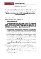
CT EXPRESS rapid-deployment CT unit.
The CT EXPRESS* rapid-deployment CT unit operates with two trucks and a three-person crew. Innovative unit layout and effective use of technology enable quick rig up and rig down and eliminate the need to climb on the unit or work under suspended loads. Process control of all pertinent CT and pumping functions improves job efficiency, economics, and operational safety. During field tests, CT EXPRESS units performed more than 200 jobs without a single lost-time incident. The simple design provides a high degree of reliability over rough terrain and in extreme climate conditions. The CT unit carries a 40,000-lbf injector and 10,000-psi wellhead pressure control equipment on a 42-ft mast. The unit can be used on wellheads up to 20 ft high, with 6-ft or shorter BHAs. Longer BHAs can be accommodated on shorter wellheads. Tubing remains stabbed during transportation, and BHAs as long as 6 ft can be made up and pressure tested before arriving on location. No hydraulic or electrical connections are made on location, which makes rig up safer and more efficient. The drop-in drum reel and innovative BOP pressure-test stand also make job preparation faster and safer.
A combination-pump tractor carries the fluid pumping and liquid-additive systems and provides electrical and hydraulic power for the unit. The trailer carries the nitrogen pumping system and liquid nitrogen storage tank. The entire system is designed to complement CT operations where pump rates are relatively low, pressures are moderate, and pumping operations continue nonstop for long periods. Although the combination pumper is designed to be operated remotely from the cab of the CT unit, local controls are also provided for standalone operation. Operational design of the CT EXPRESS unit is entirely electric over hydraulic. The operator controls both the CT unit and the pumps from the control chair, enabling better use of manpower and eliminating communication problems among operators of different units. The CT EXPRESS unit uses proven Schlumberger CoilCAT treatment for real-time data acquisition to provide information for making onsite decisions.
Coiled Tubing Surface Equipment
7
Previous | Main Menu | Contents | Search | Next
CT EXPRESS Features and Specifications Coiled Tubing Unit Tubing diameter Max. tubing length Mast height Injector Gooseneck radius BOP Sidedoor stripper Lubricator
11⁄4 in [3.2 cm], 11⁄2 in [3.8 cm], 13⁄4 in [4.4 cm] 14,500 ft of 11⁄2-in [4,420 m of 3.8 cm] tubing 42 ft [12.8 m] 40,000-lbf [177,929-N] pull 72 in [1.83 m] 31⁄16-in [7.78-cm] bore, 10,000-psi [68.95-MPa] rating 29⁄16-in bore, 10,000-psi [68.95-MPa] rating 6 ft [1.8 m] tall, 31⁄16-in [7.8-cm] diameter, 10,000-psi [68.95-MPa] rating
Integrated universal tubing length monitor Universal tubing integrity monitor Drop-in drum reel Integrated BOP pressure test stand Integrated fall arrestor and man lift Combination Pumper Continuous-service liquid pump Liquid additive pump Nitrogen pump Liquid nitrogen tank Diesel-fired vaporizer Micromotion nitrogen flowmeter Control System Fly-by-wire electric over hydraulic controls Central controls for coiled tubing and pumper inside cab of CT unit Local controls for standalone operation of combination pumper Redundant hydraulic controls for CT
0.1–2.0 bbl/min [0.02–0.32 m3/min], 10,000-psi [68.95-MPa] rating 0.1 to 0.6-galUS/min [0.38 to 2.3 L/min] with 60-galUS [227 L] reservoir 150–1,500-ft3/min [4.25–42.5 m3/min], 5,000-psi [34.47-MPa] rating 3,000 galUS [11.4 m3]
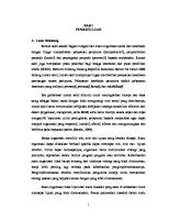
5 Conventional unit CT EXPRESS unit
4 3 2 1 0 Crew size
Trucks on location
Average rig-up hours
Average rig-down hours
Comparison between conventional and CT EXPRESS unit.
8
Well Intervention Products and Services
Previous | Main Menu | Contents | Search | Next
X-11
Modular offshore CT unit APPLICATIONS ■
Designed for all offshore applications
FEATURES ■
■
■
■
■
■
■
■
■
■ ■
■
■
■
■
Adaptable for platforms, barges, spars, floaters, and tension-leg platforms Operates with fly-by-wire controls from the control cabin to all the major skids Provides finite control of injector speed and applied forces Uses computer-controlled systems that eliminate overpull and oversnub scenarios Incorporates automatic hydraulic power pump management system Can be configured to run up to Category III well-control working pressures Offers automatic reel-brake fail-safe system Reduces the need for personnel to climb on top of the injector through use of semiautomated tubing stabbing process Monitors the condition of all the electronic, hydraulic, and pneumatic systems Works with CT sizes from 1¼ to 27⁄8 in Offers fail-safe systems that incorporate complete manual backup Enables detailed, accurate entry into the wellbore through real-time geometry inputs Provides constant monitoring of BOP system pressures and valve positions Reduces the number of hydraulic and mechanical connections required to set up Offers zoned, ATmosphere EXplosibles (ATEX), and CE-marked certified control cabin, hydraulic power pack, reel, and injector
Flexible, fit-for-purpose design
The X-11* modular offshore CT unit with active process control and automated safety systems was developed as a flexible, fit-forpurpose system that is easily adaptable for many offshore structures including platforms, barges, spars, floaters, and tension-leg platforms. The unit works with CT sizes ranging from 1¼ to 27⁄8 in, and changing from one CT size to another is safer, easier, and more efficient.
More automation, less complexity
The X-11 unit comprises five main skids: ■
a hydraulic power pack
■
a control cabin
■
a drop-in drum reel
■
two transport baskets that contain wellcontrol equipment and the injector.
Interior of the X-11 unit.
Modular in design, the hydraulic power pack, the control cabin, and the transport baskets are built in standard shipping containers, and the control cabin can stack on top of the hydraulic power pack. This design reduces the total weight and footprint of the entire CT system. The unit’s automated control system monitors well parameters and the entire electric hydraulic system. This control system detects and provides timely notification to the supervisor when changes occur. In addition to providing real-time data acquisition and data transfer to offsite locations, the X-11 unit provides one central control point for the entire CT operation. The modular package combines major CT components are easy to connect, optimize space utilization, and provide maximum versatility.
Improved safety and efficiency
The X-11 unit improves the efficiency and safety of the wellsite delivery process, while reducing the cost of the total system. Automating several key processes also reduces the number of operating personnel that is normally required. Improved crew ergonomics, a smaller footprint, and the automated monitoring and control systems allow the CT supervisor to focus on downhole job requirements rather than equipment coordination.
BENEFITS ■
■
■
Incorporates fail-safe systems to improve safety Improves efficiency and safety of the wellsite delivery process Reduces footprint through modular design concept that allows stacking
Coiled Tubing Surface Equipment
9
Previous | Main Menu | Contents | Search | Next
X-11 General Specifications Operating temperatures
–4 degF [–20 degC] to 118 degF [48 degC]
Hydraulic Power Pack Engine Engine emergency shutdown system Hydraulic pump Hydraulic circuits Accumulators Diesel tank Hydraulic tank Length × width × height Weight Lifting certification Certification
340-hp Caterpillar® C9 Tier lll engine Emergency air intake shutdown, automatic engine overspeed shutdown, gas detector sensors 250-hp triple-stack gear pump Semiclosed loop, with 3,000-psi [20.68-MPa] and 5,000-psi [34.48-MPa] circuits Three 15 galUS [0.057 m3] 150 galUS [0.57 m3] 150 galUS [0.57 m3] 10 ft × 8 ft × 8.5 ft [3.05 m × 2.44 m × 2.59 m] 25,000 lbm [11,339.8 kg] DNV† 2.7.1 ATEX‡, CE marked, Zone II compliant
Control Cabin Cabin Controls Data acquisition External monitoring (video camera system) Climate control External view Length × width × height Weight Lifting certification Certification † ‡
Pressure purged Process-controlled system CoilCAT* coiled tubing computer-aided treatment Remote spooling, stripper, two others as required 30,000-Btu cooling system 270° view 10 ft × 8 ft × 8.5 ft [3.05 m × 2.44 m × 2.59 m] 15,000 lbm [6,803.9 kg] DNV 2.7.1 ATEX, CE marked, Zone II compliant
Det Norske Veritas ATmosphere EXplosibles
X-11 in offshore Malaysia.
10
Well Intervention Products and Services
Previous | Main Menu | Contents | Search | Next
X-11 Drop-In Drum Reel System Loading Levelwind Drive system Reel swivel Circulating pressure transducer Pig launcher Ball-dropping ability Tubing monitoring Tubing lubrication (external) Tubing lubrication (internal for corrosion mitigation) Safety equipment
From top and front of power stand Floating arm type suitable for all tubing sizes, automated electronic overhydraulic spooling control Chain drive 15,000-psi [103.42-MPa] rated Integral type with double isolation valve manifold Yes Yes CT inspection device for wall thickness and ovality Automatic lubrication with applicator on levelwind, 5-galUS tank capacity Self-contained system Fall arrester, work platforms as required for levelwind access
Tubing Spool Specifications Flange outside diameter
Core diameter
Width
Tubing capacity
With 95% spooling efficiency
1¼ in 1½ in 1¾ in 2 in
37,800 ft [11,521.4 m] 26,700 ft [8,138.2 m] 19,800 ft [6,035.1 m] 14,600 ft [4,450.1 m]
Tubing capacity
With 95% spooling efficiency
142 in [3.61 m]
80 in [2.03 m]
68.5 in [1.74 m]
Flange outside diameter
Core diameter
Width
Length × width × height
1¼ in 41,300 ft [12,588.2 m] 1½ in 28,500 ft [8,686.8 m] 1¾ in 21,800 ft [6,644.6 m] 2 in na† 13.83 ft × 8.5 ft × 12.25 ft [4.22 m × 2.59 m × 3.73 m]
Weight with empty spool Weight of empty spool Skid, max. gross weight with tubing full of fluid Lifting certification Certification
19,500 lbm [8,845.1 kg] 5,700 lbm [2,585.5 kg] 100,000 lbm [45,359.3 kg] DNV 2.7.1 ATEX, CE marked, Zone II compliant
142 in [3.61 m]
70 in [1.78 m]
68.5 in [1.74 m]
Injector Specifications HR 560 configuration HR 580 configuration HR 5100 configuration Hydraulics Depth system Gooseneck Condition monitoring Safety system Lifting certification Certification
60,000 lbf pull, 26,000 lbf snub [266,893 N pull, 115,654 N snub] 80,000 lbf pull, 40,000 lbf snub [355,858 N pull, 177,929 N snub] 100,000 lbf pull, 50,000 lbf snub [444,822 N pull, 222,411 N snub] 5,000-psi [34.48-MPa] circuit with condition monitoring systems Universal tubing length monitor mounted below the injector chains 72-in [1.83-m] gooseneck with overload protection system, set up for 1¼-in [3.175-cm] to 27⁄8-in [7.303-cm] CT 100-in [2.54-m] gooseneck with overload protection system, set up for 1¼-in [3.175-cm] to 27⁄8-in [7.303-cm] CT Metallic chip detection and temperature sensors Fall arrester system DNV 2.7.1 ATEX, CE marked, Zone l compliant
Coiled Tubing Surface Equipment
11
Previous | Main Menu | Contents | Search | Next
X-11 BOP Control Station Operation Mode of operation Certification
Can operate two strippers, two dual combi or one quad BOP system, and kill and flow valves From control cabin or from control station, with automatic ram position detection and feedback to the control system ATEX, CE marked, Zone ll compliant
Well Control Equipment BOP Stripper 2-ft riser 4-ft riser 8-ft riser
10,000-psi [68.95-MPa] dual combi 4.06-in [10.31-cm] bore slidelock BOP 4.06 in [10.31 cm], 10,000 psi [68.95 MPa] 4.06 in [10.31 cm], 10,000 psi [68.95 MPa] 4.06 in [10.31 cm], 10,000 psi [68.95 Mpa] 4.06 in [10.31 cm], 10,000 psi [68.95 MPa]
Injector Transport Basket
Injector, stripper, injector legs
Length × width × height Weight Gross weight, fully loaded Lifting certification Certification
10 ft × 8 ft × 9.5 ft [3.05 m × 2.44 m × 2.89 m] 6,000 lbm [2,721.6 kg] 28,000 lbm [12,700.6 kg] DNV 2.7.1 CE marked
Well Control Transport Basket
BOP, gooseneck, BOP control cart, risers, stairs
Length × width × height Weight Gross weight, fully loaded Lifting certification Certification
10 ft × 8 ft × 9.5 ft [3.05 m × 2.44 m × 2.89 m] 6,000 lbm [2,721.6 kg] 28,000 lbm [12,700.6 kg] DNV 2.7.1 CE marked
Options Soundproofed power pack Max. average sound pressure level Operating temperatures Certification
80 dB –4 degF [–20 degC] to 108 degF [42 degC] ATEX, CE marked, Zone ll compliant
Reel conversion skid
Certification †
Adapts to conventional CT reels and provides all the reel control features ATEX, CE marked, Zone ll compliant
Not available
12
Well Intervention Products and Services
Previous | Main Menu | Contents | Search | Next
CT SEAS
Automated offshore CT unit APPLICATIONS ■
Offshore coiled tubing (CT) operations in demanding environments on fixed and floating facilities
ADVANTAGES ■
Increases safety and efficiency
■
Lowers operating costs
■
Reduces the number of lifts required (typically from 53 to 36)
Increased safety and efficiency With components modularized into 10 primary skids, CT SEAS* automated offshore CT unit reduces time for offshore CT operations.
Modular assembly An ergonomically designed cabin enhances operator control while reducing personnel requirements, rig-up time, and costs. Pretested, preassembled modules make field assembly efficient and minimize the chances for human error during rig up. A reduction in the number of hydraulic connections saves time and reduces the risk of contamination. Single-bolt locking unions and other time saving devices enhance efficiency.
■
Reduces personnel by up to 30%
Safer, more efficient CT system
■
Reduces rig-up time
■
Reduces operating time
The CT SEAS unit is flexible, fit-for-purpose, and readily adaptable for many offshore structures, including platforms, floaters, and tension-leg platforms. The system has all the capabilities of a conventional CT unit.
FEATURES ■
Usability in all CT operations
■
Ten primary skids
■
■
■
■ ■
The unit is beneficial in all operations in which many runs are conducted in the same well. Typically, these operations include long postfracturing cleanouts. System design elements and improved ergonomics enhance safety and save time.
Reduced mechanical and hydraulic coupling on location
■ ■
Preassembled and tested equipment modules and manifolds Soundproofed, zoned, ATtmospheric EXplosives (ATEX) compliant hydraulic power unit Modularized hydraulic connections
The process control architecture allows faster, safer operations. Single-point control of CT, choke manifold, and pump improves safety and helps the engineer focus on the task at hand.
■
Modules allow efficient transition between wells on sequential multiwell operations.
■
Personnel reduction improves operational efficiency and safety.
■
More efficient use of space through a modular design benefits platform operations, limits boat space requirements, and reduces the number of crane lifts.
Automatic stabbing of tubing into injector head
■
Reduction in high elevation work
■
Improved pressure testing
The CT SEAS unit only has 10 primary skids, which cuts crane lifts off the boat to 36 from 53 in typical operations.
Coiled Tubing Surface Equipment
13
Previous | Main Menu | Contents | Search | Next
CT SEAS
General Specifications Operating temperatures Hydraulic Power Pack Engine Engine emergency shutdown system Hydraulic pumps Hydraulic circuits Length × width × height Weight Lifting certification Certification Control Cabin Cabin Controls Data acquisition External monitoring (video camera system) External view Length × width × height Weight Lifting certification Certification † Det
14
–4 degF [–20 degC] to 108 degF [42 degC] 500-hp Detroit Diesel Series 60® Emergency air intake shutdown, automatic engine overspeed shutdown, gas detector sensors P16 / P14 Closed loop, 3,000 psi [20.68 MPa], and 5,000 psi [34.48 MPa] 21.3 ft × 11.5 ft × 8.2 ft [6.5 m × 3.5 m × 2.5 m] 19 metric tons DNV† 2.7.1 ATEX, Zone II compliant Pressure-purged A60 Process-controlled system CoilCAT* coiled tubing computer-aided treatment Remote spooling, stripper, two others as required 270° view 14.8 ft × 8.2 ft × 9.8 ft [4.5 m × 2.5 m × 3 m] 7.5 metric tons DNV 2.7.1 ATEX, Zone II compliant
Norske Veritas
Well Intervention Products and Services
Previous | Main Menu | Contents | Search | Next
CT SEAS Drop-In Drum Reel System Loading Reel swivel Safety equipment Tubing Spool Specifications 27⁄8-in tubing capacity Length × width × height Weight with empty spool Lifting certification Certification Injector Specifications HR 5100 configuration Injector connector Hydraulics Depth system Gooseneck Condition monitoring Safety system Lifting certification Certification Well Control Equipment BOP Safety head Stripper Risers
From top and front of power stand 15,000-psi [103.42-MPa] rated Fall arrester, work platforms as required for levelwind access 19,685 ft [6,000 m] 17.2 ft × 10.9 ft × 17.1 ft [5.3 m × 3.3 m × 5.2 m] 14 metric tons DNV 2.7.1 ATEX, Zone II compliant 100,000 lbf pull, 50,000 lbf snub [444,822 N pull, 222,411 N snub] 5.125-in [13.02-cm] mechanical connector 5,000-psi [34.37-MPa] circuit with condition monitoring systems Universal tubing length monitor mounted below the injector chains Trifold 120-in [3.05-m] gooseneck with overload protection system, set up for 27⁄8-in [7.303-cm] CT Metallic chip detection and temperature sensors Fall arrester system DNV 2.7.1 ATEX, Zone l compliant
The CT SEAS unit offers an ergonomically designed cabin which enhances operator control while reducing personnel requirements, rig-up time, and costs.
5.125-in [13.02-cm], 10,000-psi [68.95-MPa] triple 5.125-in [13.02-cm], 15,000-psi [103.42-MPa] single shear 4.06-in [10.31-cm], 10,000-psi [68.95-MPa] dual stripper 5.125 in [13.02 cm], 15,000 psi [103.42 MPa]
Coiled Tubing Surface Equipment
15
Previous | Main Menu | Contents | Search | Next
Catenary Intervention Floating vessel intervention system APPLICATIONS ■
Matrix stimulation
■
Water or scale control
■
Fill cleanout
■
CoilTOOLS* coiled tubing intervention tools and solutions
■
Zonal isolation and reperforation
■
Fracturing through CT
■
CT drilling
BENEFITS ■
Reduces total intervention cost
■
Increases profitability and production life
■
■
Enables treatment of previously inaccessible wells Provides safer operations in adverse weather conditions
FEATURES ■
Allows access to small offshore platforms with limited deck space and loading capacity
■
Reduces number of trips to port
■
Enables rapid deployment and rig up
■
Offers satellite and datalink capability using InterACT* global connectivity, collaboration, and information service
ReelCONNECT* seamless technology for connecting multiple coiled tubing strings assembly skid.
A more efficient CT intervention technique Interventions on small platforms with limited deck space and loading capacity often require the use of jackup barges, lift boats, or workover rigs. The high cost and limited availability of these offshore vessels has delayed or prevented many required interventions, leaving a number of wells nonproductive or producing below their optimal capacity. The catenary CT intervention technique uses smaller floating vessels and proprietary safety and wellcontrol systems that eliminate the need to lift the CT reel and the pumping equipment to the platform. The associated reduction in total intervention cost—and the ability to work on extremely small platforms—enables operators to perform interventions that increase profitability and production life.
16
Well Intervention Products and Services
Previous | Main Menu | Contents | Search | Next
Catenary Intervention The floating vessel approach Schlumberger has successfully used different types of small floating vessels for a number of years to perform offshore CT interventions. These vessels, which include anchored barges, dynamically positioned vessels, and standard supply boats, enable CT intervention on almost any offshore installation. Full-scale CT operations have been performed from supply boats with deck space as limited as small as 16 × 9 m. With at least four vessel anchoring points in place, operations can be performed with wave heights up to 5 m. With a draft under 5 m, the floating CT system is an ideal solution for performing well intervention work, particularly for wells located on small-front platforms or platforms that prohibit placing CT and pumping equipment onboard. The catenary system reduces total intervention time by approximately 25%, with less time needed for transferring equipment to platform, rigging up, and pressure testing. In addition, a shorter advance notice period is required for job preparation and mobilization. CT Unit Specifications Power pack Control cabin
16,000 lbm [7,258 kg] Zone II, Division I compliant 16,000 lbm [7,258 kg] Hydraulic or electrical over hydraulic Air conditioned 300-bhp engine
Reel Injector skid
12,000–16,000 lbm [5,443–7,258 kg] 22,000 lbm [9,979 kg] total weight, including injector, BOPs, stripper, and accessories Injector head typical weight: 13,000 lbm [5,897 kg] Pull: 80,000–100,000 lbf [355,858–444,822 N] Snub: 40,000 lbf [177,929 N]
Data acquisition Options
CoilCAT* coiled tubing computer-aided treatment Soundproof engine package (85 dB at 7 m [23 ft]) Zone II compliant DNV† certification Larger reel or use of clip-in drum Larger pressure control ID Higher pressure rating (Category 2 operations)
Catenary system, power pack, and cabin Engine-air-cooled turbo diesel Shear-and-seal device for an emergency disconnect Automatic tensioning device that compensates for wave action Video monitoring and relay of operations that occur out of the operator’s line of sight Dedicated cabin with reel drive, tensioner, and levelwind controls † Det
Norske Veritas
Coiled Tubing Surface Equipment
17
Previous | Main Menu | Contents | Search | Next
ACTive Portfolio
Previous | Main Menu | Contents | Search | Next
ACTive
Family of live downhole coiled tubing services APPLICATIONS
Technology platform
■
Treatment monitoring
■
Real-time logging and treating
■
Intervening while the BHA is still in hole
The portfolio of ACTive services provides live downhole measurements conveyed on CT that is enabled by fiber-optic telemetry. The system consists of a BHA, surface electronics, and dynamic interpretation software. It provides pressure readings inside and outside of the CT BHA, downhole and distributed temperature survey along the wellbore, casing collar locator, and depth correlation. An alternative downhole BHA allows combining real-time fiber-optic telemetry with existing advanced wireline production logging tools, making high-quality production logging data available during intervention—when it matters most.
BENEFITS ■
■
Improved production because the treatment is optimized with real-time data Reduced costs because monitoring, optimization, and intervention can be accomplished in one run
FEATURES ■ ■
■
■ ■
■ ■
Real-time fiber-optic telemetry Real-time downhole quality check of tools with feedback validating downhole measurements
Enhanced downhole technology
Distributed temperature survey (DTS) that provides a 3D temperature profile of the entire wellbore Monitoring of injection rates and pressure Coiled tubing intervention and the most advanced production logging in one run Accurate depth control for perforating Accurate downhole pressure-buildup monitoring for well testing The ACTive family of live coiled tubing services uses fiber-optic CT to collect real-time measurements and optimize treatments while they are still in progress.
Innovative CT intervention
The ACTive* family of live coiled tubing services enables downhole measurement, interpretation, and job optimization. These services provide the information needed to adjust job parameters, improve effectiveness, reduce risks, and optimize performance when it matters most— while the treatment is still in progress.
The enhanced ACTive services downhole technology platform—through state-of-the-art electronics and sensors—delivers premium pressure measurements, improved power management, and modularity for increased confidence and overall job efficiency during a CT intervention. Real-time gamma ray and tension and compression measurements are the latest offerings in the portfolio of ACTive services. These new measurements add to the technology platform to enable informed, realtime decisions, operational control, and higher value services. ACTive real-time CT services give you the opportunity to monitor and evaluate job progress, optimize treatment results, and intervene with one run in the hole.
For every application, a customized live downhole CT service helps maximize treatment efficiency and reservoir performance.
Well Intervention Products and Services
■
ACTive Portfolio
Previous | Main Menu | Contents | Search | Next
21
ACTive ACTive Matrix* live CT stimulation and conformance service optimizes CT matrix stimulation through live monitoring of injection rates and downhole pressure and temperature to allow maximum fluid penetration and diversion and to optimize treatment volumes. This realtime process improves current treatment performance and enhances the design of subsequent treatments. ACTive Isolation* live CT zonal isolation service achieves accurate depth setting, sealing element operation and integrity, and fluid placement intended for performing temporary or permanent CT zonal isolation, all in a single run. Controlling the pressure differential across the sealing elements and tools improves performance and reduces operational risk. Where precise, controlled fluid placement is required, the ACTive Straddle* CT real-time multiset inflatable packer extends critical zonal isolation to previously inaccessible environments, with the ability to treat multiple zones in single intervention. ACTive Cleanout* live CT wellbore fill removal service enables efficient and effective CT fill cleanout by avoiding formation dam-
age, reducing the number of trips and the total operating time, and optimizing fluid volume and penetration rate into the fill. Active monitoring of the pressure differential across the BHA greatly improves performance. ACTive Lift* live CT nitrogen lifting service improves CT nitrogen lift operation time and fluid efficiency based on continuous monitoring of wellbore pressure, leading to faster and more controlled restoration of well production while avoiding solids production. This service also aids field performance characterization and artificial lift evaluation. ACTive Perf* live CT perforating service achieves accurate depth control in a single run and ensures target zone coverage while selectively perforating. Controlling hydrostatic balance avoids formation damage, formation fluid invasion, and formation sanding. Verification of gun activation leads to improved CT perforating safety and reliability. Going beyond conventional CT perforating, the ACTive OptiFIRE* CT real-time selective perforating and activation system provides an even safer, more efficient method for CTconveyed perforating.
ACTive Specifications Surface (optical acquisition module mounted inside the CT reel)
Downhole
Measurements Pressure
Temperature CCL depth correlation
22
Temperature rating Power requirement Data communication Total tool length Outside diameter Pressure rating Temperature rating Tension (max. pressure) Compression (max. pressure) Maximum torque Flow rate (through the tool) Material
–13 to 120 degF [–25 to 49 degC] 12 V DC Wireless 7.2 ft [2.18 m] 2.125 in [5.4 cm] 12,500 psi [86.2 MPa] at maximum tension 15,000 psi [103.4 MPa] at 0 tension 300 degF [150 degC] 45,000 lbf [200.2 kN] 10,000 lbf [44.5 kN] 800 lbf.ft [1,084.7 N.m] 2 bbl/min [238.5 L/min] clean fluid NACE compliant
Accuracy Repeatability Resolution Stability Resolution Accuracy Completion size Adjustable gain Logging speed
±3 psi 0.15 psi 0.075 psi 0.2 psi drift over 100 h 0.03 degF [0.017 degC] ±1 degF [0.5 degC] 3½-in to 7-in casing Low (1x), medium (4x), high (8x) 10 to 120 ft/min
ACTive PS* live CT production logging service enables combining advanced openhole and cased hole production logging with all ACTive services. The combination of distributed measurements—both acoustic and temperature—can be captured and synergistically combined with the already robust production logging data to get the most accurate picture of well production. ACTive Profiling* live CT distributed temperature sensing service enhances all ACTive services with DTS profiling to provide a 3D temperature profile of the entire wellbore to monitor treatment fluid placement and well production performance. Temperature profiling provides the ability to perform active point measurements and DTS spatial measurements in the same run.
Measure, interpret, act
ACTive services enable continuous downhole monitoring of your job. Continuous monitoring makes it possible for you to watch events as they unfold to build an exact picture of progress and to alert you to any issues as they are encountered. As you monitor, you gain unique quantitative feedback and insight directly from the wellbore in real time. Real-time interpretation through Decipher* interpretation of coiled tubing dynamic surface and downhole events provides the information you need to crossreference what you are seeing downhole with surface and petrophysical data for a dynamic assessment of service performance. When you know what is happening downhole, you can act with a greater degree of confidence. For the first time, you can adjust job parameters based on real-time downhole information to optimize performance. With ACTive services, you gain the confidence to act decisively. Distributed temperature sensing creates a 3D temperature profile.
Well Intervention Products and Services
Previous | Main Menu | Contents | Search | Next
ACTive GR Live CT gamma ray logging tool APPLICATIONS ■
■
■
Accurate depth correlation in real time during a CT intervention Qualitative evaluation of lithology and shale content Radioactive tracer monitoring for stimulation applications
BENEFITS ■
■
Improves performance and reduces risk with precise tool positioning Enhances operational efficiency by providing downhole data in real time
FEATURES ■
■
■
■
Ruggedized version for use during perforating operations Pump-through capability for CT intervention and gamma ray (GR) log in the same run Ball-drop capability through the tool for activation of tools below Plug-and-play combination with enhanced ACTive* family of live coiled tubing services
Gamma ray measurements of subsurface formations gathered in real time while maintaining pump-through capability.
Accurate depth correlation GR measurements are available with the ACTive services which provide downhole measurements in real time, conveyed on CT that is enabled by fiber-optic telemetry. The ACTive GR* live CT gamma ray logging tool detects naturally occurring gamma rays in the formations adjacent to the wellbore, while maintaining pump-through capability for CT intervention. The service provides you with an industrystandard measurement for depth correlation in real time.
ACTive Portfolio
23
Previous | Main Menu | Contents | Search | Next
ACTive GR The optional GR tool enhances other ACTive services when run in combination. For instance, ACTive Perf* live CT perforating service is further enhanced allowing accurate depth control and perforating the target zone in a single run, while monitoring the hydrostatic balance with the integral pressure sensor. ACTive Matrix* live CT stimulation and conformance service can further enhance fluid placement by combining distributed temperature measurements with monitoring of radioactive tracers in stimulation fluids. ACTive GR Tool Specifications Model Equipment specifications OD, in Makeup length , in Total weight, lbm Max ball drop size, in Flow path diameter, in Material Operational specifications Operating temperature, degF Pressure rating, psi Tensile strength, lbf Max. torque, ft.lbf Max. flow rate, bbl/min Fluid compatibility Shock rating Rated for perforation jobs
GRSM 2.500 39.88 20 7⁄ 16 0.500 NACE compliant 300 12,500 (at max. tensile rating) 45,000 (at max. pressure rating)
GRNM 2.375 37.52 20 5⁄ 8 0.688 NACE compliant 300 12,500 (at max. tensile rating) 45,000 (at max. pressure rating) 800 800 1.5 2 All common treating fluids includ- All common treating fluids including acid and H2S ing acid and H2S 12,000 shocks at 250 gn/ms 12,000 shocks at 250 gn/ms 40 shocks at 3,800 gn/0.3 ms Yes No
GRSM: Gamma ray shock model GRNM: Gamma ray nonshock model
12,770
Reference log 12,760
Log from ACTive GR tool 12,770
CT bottomhole pressure
12,780
Annulus bottomhole pressure
12,790
12,800
Pump rate
CT speed CT weight
12,810
Casing collar locator 12,820
12,830
12,840
12,850
HPHT ACTive services CT perforation report.
24
Well Intervention Products and Services
Previous | Main Menu | Contents | Search | Next
ACTive TC Live CT tension and compression tool APPLICATIONS ■
■
■ ■
■
■
Coiled tubing (CT) operations in deviated and horizontal wells Positive indication of latching or jar activation during fishing Confirmation of sliding sleeve activation Confirmation of completion hardware manipulation Positive indication of inflatable packer setting Indication of perforating guns firing
BENEFITS ■
Greater efficiency and control
■
Reduced risk of unsuccessful operations
FEATURES ■
■
■
■
■
Downhole load and torque measurements in real time Robust design for use during perforating and fishing operations Pump-through capability to allow CT intervention in the same run Ball-drop capability through the tool for activation of tools below Plug-and-play combinability with enhanced ACTive* family of live coiled tubing services
Tension and compression measurements in real time ensure shifting tools are properly engaged, and provide confirmation of shifting sleeve activation.
Interventions with greater confidence and success ACTive TC* live CT tension and compression tool provides downhole load and torque measurements in real time with the ACTive family of live CT services, while maintaining pump-through capability. The measurements are conveyed on CT that is enabled by fiber-optic telemetry. Effective in a wide range of downhole environments, the ACTive TC tool eliminates errors introduced by extrapolating surface measurements for downhole-load-sensitive operations. You can adjust job parameters based on real-time downhole information and carry out interventions with increased confidence and success.
ACTive Portfolio
25
Previous | Main Menu | Contents | Search | Next
ACTive TC Combining TC measurements with other ACTive services measurements like pressure, temperature, gamma ray, and casing collar location enhances the in-well live family of CT services. Monitoring critical downhole CT load parameters to achieve successful isolation in deviated and horizontal wells improves the effectiveness of ACTive Isolation* live CT zonal isolation services. ACTive services involving fishing or manipulation of completion hardware benefit from the accurate indication of latching, releasing, and jar and accelerator activation, when wellbore conditions do not allow a clear surface indication. ACTive TC Tool Specifications Equipment OD specifications Makeup length
Operational specifications
Measurement specifications
Total weight Flow path diameter Max. ball drop size Operating temperature Pressure rating, Tensile strength Max. torque Max. flow rate Fluid compatibility Max. proppant concentration Pressure compensated measurements Axial load range Axial load accuracy
0
15,000
–100
14,500
–200
14,000
–300
13,500
–400
13,000
–500
12,500
■ Downhole load
–600 5,865
5,870
5,875 Depth, ft
5,880
CT weight, lbf
Downhole load, lbf
Axial load resolution Torque range Torque accuracy Torque resolution
2.125 in 47.80 in 38 lbm 0.688 in 5 ⁄ 8 in 300 degF 12,000 psi (at max tensile rating) 45,000 lbf (at max pressure rating) 800 ft.lbf 2 bbl/min All common treating fluids including acid. H2S compatible 0.45 kg Yes –10,000 to 45,000 lbf Absolute: 500 lbf + 1% Applied Localized: 2% Applied