![IPASOLINK 400 Maintenance [PDF]](https://pdfs.asia/img/200x200/ipasolink-400-maintenance.jpg)
16 0 8 MB
Submission Prohibited NEC Group Internal Use Only -1-
iPASOLINK 400
SECTION III
MAINTENANCE
CONTENTS CONTENTS ............................................................................................................................- 1 1.
General .......................................................................................................................... 1-1
2.
Precaution .................................................................................................................... 2-1 2.1
Maintenance and Operation Manual ....................................................................................... 2-4
2.1.1
Wrist Strap Connection.................................................................................................... 2-4
2.1.2
Maintenance Mode Setting (for the LCT Operation) ........................................................ 2-4
2.1.3
Manual Switch Operation ................................................................................................ 2-9
3.
Current Status .............................................................................................................. 3-1 3.1
4.
Current Status......................................................................................................................... 3-1
Routine Maintenance ................................................................................................... 4-1 4.1
Meter Reading ........................................................................................................................ 4-1
4.2
Performance Monitoring ......................................................................................................... 4-3
4.2.1
PM Parameters ............................................................................................................... 4-3
4.2.1.1
5.
PM Status Monitor Types ....................................................................................... 4-3
Corrective Maintenance .............................................................................................. 5-1 5.1
Alarm/Status ........................................................................................................................... 5-2
5.1.1
Alarm Management ......................................................................................................... 5-7
5.1.1.1 5.1.2
Maintenance
Alarm Class............................................................................................................ 5-7 Alarm and Status Indication Detail .................................................................................. 5-8
5.1.2.1
ODU Alarms & Status ............................................................................................ 5-8
5.1.2.2
MODEM-A/EA Alarms & Status ............................................................................. 5-9
5.1.2.3
STM1-A Option Card Alarms & Status ................................................................. 5-10
5.1.2.4
16E1-A Option Card Alarms & Status .................................................................. 5-12
5.1.2.5
AUX-A Option Card Alarms & Status ................................................................... 5-12
5.1.2.6
GbE-A Option Card Alarms & Status ................................................................... 5-13
5.1.2.7
MSE-A Option Card Alarms & Status................................................................... 5-13
5.1.2.8
PTP-A Option Card Alarms & Status ................................................................... 5-14
5.1.2.9
MC-A4 Alarms & Status ....................................................................................... 5-15
5.1.2.10
Radio Traffic Aggregation Link Alarm .................................................................. 5-17
5.1.2.11
ETH GRP Alarm ................................................................................................... 5-17
5.1.2.12
IEEE802.3ah Alarm ............................................................................................. 5-17
NWD-115477-06E September, 2013
Submission Prohibited NEC Group Internal Use Only -2-
5.1.2.13
6.
TCN Alarms ......................................................................................................... 5-18
Control Items ................................................................................................................ 6-1 6.1
Loopback ................................................................................................................................ 6-2
6.1.1
IF Loopback..................................................................................................................... 6-2
6.1.1.1
IF Loopback ........................................................................................................... 6-3
6.1.2
L2 Loopback .................................................................................................................... 6-9
6.1.3
TDM Loopback Control.................................................................................................. 6-12
6.1.3.1
TDM Loopback Control (E1 Loopback1) .............................................................. 6-12
6.1.3.2
TDM Loopback Control (E1 Loopback2) .............................................................. 6-16
6.1.3.3
TDM Loopback Control (STM-1 Loopback1)........................................................ 6-19
6.1.3.4
TDM Loopback Control (STM-1 Loopback2)........................................................ 6-22
6.1.3.5
Link OAM Loopback ............................................................................................. 6-25
6.2
Equipment Maintenance ....................................................................................................... 6-28
6.2.1
Equipment Utility ........................................................................................................... 6-28
6.2.1.1
Database Upload (Export (NE->Storage) Utility) .................................................. 6-28
6.2.1.2
Database Download (Update (Storage->NE) Utility) ............................................ 6-31
6.2.1.3
Program ROM Switching...................................................................................... 6-65
6.2.1.4
USB Memory Utility .............................................................................................. 6-71
6.2.1.5
Log Clear Function............................................................................................... 6-72
6.2.1.6
Provisioning Clear Function ................................................................................. 6-74
6.2.1.7
Current Time Setting ............................................................................................ 6-75
6.2.2
Equipment Reset ........................................................................................................... 6-78
6.2.2.1
H/W Reset Control ............................................................................................... 6-79
6.2.2.2
F/W Reset Control ............................................................................................... 6-83
6.2.3
Radio Control ................................................................................................................ 6-87
6.2.3.1
ATPC Manual Control .......................................................................................... 6-88
6.2.3.2
TX Mute Control ................................................................................................... 6-91
6.2.3.3
CW Control .......................................................................................................... 6-96
6.2.3.4
TX Modulation Manual Control (for AMR Mode only) ........................................... 6-99
6.2.4
Laser Management...................................................................................................... 6-102
6.2.4.1
Laser Shutdown Control .................................................................................... 6-102
6.2.4.2
ALS Manual Switch Control ............................................................................... 6-105
6.2.5
Cluster Alarm Setting................................................................................................... 6-107
6.2.6
Inventory...................................................................................................................... 6-111
6.2.6.1 6.2.7 6.3
Equipment Inventory Information ....................................................................... 6-111 Software License Key Information ............................................................................... 6-119
Performance Monitor .......................................................................................................... 6-123
6.3.1
Link Performance Monitor ........................................................................................... 6-123
6.3.2
Monitor Report ............................................................................................................. 6-123
NWD-115477-06E
6.3.2.1
MODEM PMON Report ...................................................................................... 6-123
6.3.2.2
E1 PMON Report ............................................................................................... 6-127
Maintenance
Submission Prohibited NEC Group Internal Use Only -3-
6.3.2.3
STM-1 PMON Report ......................................................................................... 6-131
6.3.2.4
ETH RMON Report ............................................................................................ 6-139
6.3.2.5
VLAN Counter Report ........................................................................................ 6-143
6.3.2.6
PMON/RMON/FDB Clear................................................................................... 6-144
6.4
Offline Maintenance ............................................................................................................ 6-151
6.4.1
DADE Adjustment........................................................................................................ 6-151
6.4.2
RF Sub Band Selection ............................................................................................... 6-153
6.5
Maintenance Test ............................................................................................................... 6-157
6.6
Software License Setup ...................................................................................................... 6-165
7.
Trouble Shooting ......................................................................................................... 7-1 7.1
Trouble Shooting Flow ............................................................................................................ 7-1
7.2
Replacement for Radio Portion ............................................................................................... 7-6
7.2.1
ODU Replacement .......................................................................................................... 7-6
7.2.2
IDU Replacement .......................................................................................................... 7-12
7.2.2.1 7.2.3 7.3
IDU Replacement................................................................................................. 7-12 Fuse Replacement ........................................................................................................ 7-15
Trouble Clearing Details ....................................................................................................... 7-15
7.3.1
Making Contact with NEC.............................................................................................. 7-15
7.3.2
Retrieve Alarm Information ............................................................................................ 7-15
7.3.2.1 7.3.3
ODU Alarm .................................................................................................................... 7-16
7.3.3.1
ODU Alarm........................................................................................................... 7-16
7.3.3.2
TX Power ............................................................................................................. 7-17
7.3.3.3
TX Input ............................................................................................................... 7-17
7.3.3.4
RX Level .............................................................................................................. 7-17
7.3.3.5
ODU CPU / Cable Open ...................................................................................... 7-17
7.3.3.6
LO REF ................................................................................................................ 7-17
7.3.3.7
ODU Type Mismatch ............................................................................................ 7-18
7.3.3.8
ODU Power Supply .............................................................................................. 7-18
7.3.4
Maintenance
Display Current Alarm .......................................................................................... 7-15
MC-A4 Alarm ................................................................................................................. 7-18
7.3.4.1
Module ................................................................................................................. 7-18
7.3.4.2
Bus Error .............................................................................................................. 7-18
7.3.4.3
Unequipped (PS) ................................................................................................. 7-19
7.3.4.4
Power Supply (PS) ............................................................................................... 7-19
7.3.4.5
FAN FAIL ............................................................................................................. 7-20
7.3.4.6
Unequipped (FAN) ............................................................................................... 7-20
7.3.4.7
EXT CLK Unequipped .......................................................................................... 7-20
7.3.4.8
EXT CLK Type Mismatch ..................................................................................... 7-21
7.3.4.9
IDU CPU Alarm .................................................................................................... 7-21
7.3.4.10
Memory FAIL ....................................................................................................... 7-21
7.3.4.11
USB FAIL ............................................................................................................. 7-22
NWD-115477-06E
Submission Prohibited NEC Group Internal Use Only -4-
7.3.4.12
Temperature ........................................................................................................ 7-22
7.3.4.13
CLK FAIL ............................................................................................................. 7-22
7.3.4.14
CLK Drift .............................................................................................................. 7-23
7.3.4.15
LTI ........................................................................................................................ 7-24
7.3.4.16
SSM Fail .............................................................................................................. 7-24
7.3.4.17
EXT CLK LOS ...................................................................................................... 7-24
7.3.4.18
EXT CLK AIS ....................................................................................................... 7-25
7.3.4.19
EXT CLK LOF ...................................................................................................... 7-25
7.3.4.20
EXT CLK Loop ..................................................................................................... 7-25
7.3.4.21
E1 LOS ................................................................................................................ 7-26
7.3.4.22
E1 AIS .................................................................................................................. 7-26
7.3.4.23
PPS FAIL ............................................................................................................. 7-27
7.3.4.24
Usage Error.......................................................................................................... 7-27
7.3.4.25
ETH LOS.............................................................................................................. 7-27
7.3.4.26
ETH TF ................................................................................................................ 7-28
7.3.4.27
SFP Type Mismatch (ETH) .................................................................................. 7-28
7.3.4.28
SFP Removed (ETH) ........................................................................................... 7-29
7.3.4.29
LAN LINK ............................................................................................................. 7-29
7.3.4.30
ETH-OAM LOC .................................................................................................... 7-30
7.3.4.31
ETH-OAM Mismerge ............................................................................................ 7-30
7.3.4.32
ETH-OAM Unexpected MEP................................................................................ 7-31
7.3.4.33
ETH-OAM RDI ..................................................................................................... 7-31
7.3.4.34
License Mismatch ................................................................................................ 7-32
7.3.5
NWD-115477-06E
MODEM-A/EA Alarm ..................................................................................................... 7-32
7.3.5.1
Unequipped.......................................................................................................... 7-32
7.3.5.2
Type Mismatch..................................................................................................... 7-33
7.3.5.3
Communication FAIL ........................................................................................... 7-33
7.3.5.4
Module ................................................................................................................. 7-33
7.3.5.5
Tx Bus Error ......................................................................................................... 7-34
7.3.5.6
Rx Bus Error ........................................................................................................ 7-34
7.3.5.7
LOF ...................................................................................................................... 7-34
7.3.5.8
Frame ID .............................................................................................................. 7-35
7.3.5.9
High BER ............................................................................................................. 7-35
7.3.5.10
Low BER .............................................................................................................. 7-35
7.3.5.11
Early Warning ...................................................................................................... 7-36
7.3.5.12
MOD .................................................................................................................... 7-36
7.3.5.13
IF Cable Short ...................................................................................................... 7-36
7.3.5.14
XIF ....................................................................................................................... 7-37
7.3.5.15
L2SYNC Loss ...................................................................................................... 7-37
7.3.5.16
RDI ....................................................................................................................... 7-37
7.3.5.17
UAE ..................................................................................................................... 7-38
Maintenance
Submission Prohibited NEC Group Internal Use Only -5-
7.3.5.18
XPIC Mode Mismatch .......................................................................................... 7-38
7.3.5.19
TDM / AMR Range Mismatch .............................................................................. 7-38
7.3.5.20
Unlocked .............................................................................................................. 7-38
7.3.5.21
MODEM Power Supply Alarm .............................................................................. 7-39
7.3.5.22
Compression Setting Mismatch ........................................................................... 7-39
7.3.5.23
Radio Transmission Mode Mismatch ................................................................... 7-39
7.3.6 7.3.6.1
Unequipped.......................................................................................................... 7-40
7.3.6.2
Type Mismatch..................................................................................................... 7-40
7.3.6.3
Communication FAIL ........................................................................................... 7-41
7.3.6.4
Module ................................................................................................................. 7-41
7.3.6.5
TX Bus Error ........................................................................................................ 7-41
7.3.6.6
RX Bus Error ........................................................................................................ 7-41
7.3.6.7
SFP Type Mismatch ............................................................................................. 7-42
7.3.6.8
SFP Removed...................................................................................................... 7-42
7.3.6.9
STM-1LOS ........................................................................................................... 7-43
7.3.6.10
TF ........................................................................................................................ 7-43
7.3.6.11
RS LOF ................................................................................................................ 7-44
7.3.6.12
RS TIM ................................................................................................................. 7-44
7.3.6.13
RS EXC................................................................................................................ 7-44
7.3.6.14
RS DEG ............................................................................................................... 7-45
7.3.6.15
MS AIS ................................................................................................................. 7-45
7.3.6.16
MS RDI ................................................................................................................ 7-46
7.3.6.17
AU AIS ................................................................................................................. 7-46
7.3.6.18
AU LOP ................................................................................................................ 7-47
7.3.6.19
HP UNEQ............................................................................................................. 7-47
7.3.6.20
HP TIM ................................................................................................................. 7-47
7.3.6.21
HP PLM................................................................................................................ 7-48
7.3.6.22
HP RDI ................................................................................................................. 7-48
7.3.6.23
LOM ..................................................................................................................... 7-49
7.3.6.24
TU AIS ................................................................................................................. 7-49
7.3.6.25
TU LOP ................................................................................................................ 7-49
7.3.6.26
LP UNEQ ............................................................................................................. 7-50
7.3.6.27
LP-RDI ................................................................................................................. 7-50
7.3.6.28
LP-PLM ................................................................................................................ 7-51
7.3.7
Maintenance
STM1-A Alarm ............................................................................................................... 7-40
16E1-A Alarm ................................................................................................................ 7-51
7.3.7.1
Unequipped.......................................................................................................... 7-51
7.3.7.2
Type Mismatch..................................................................................................... 7-52
7.3.7.3
Communication FAIL ........................................................................................... 7-52
7.3.7.4
Module ................................................................................................................. 7-52
7.3.7.5
TX Bus Error ........................................................................................................ 7-53
NWD-115477-06E
Submission Prohibited NEC Group Internal Use Only -6-
7.3.7.6
RX Bus Error ........................................................................................................ 7-53
7.3.7.7
E1 LOS ................................................................................................................ 7-53
7.3.7.8
E1 AIS .................................................................................................................. 7-54
7.3.7.9
Usage Error.......................................................................................................... 7-54
7.3.8 7.3.8.1
Unequipped.......................................................................................................... 7-54
7.3.8.2
Type Mismatch..................................................................................................... 7-55
7.3.8.3
Communication FAIL ........................................................................................... 7-55
7.3.8.4
Module ................................................................................................................. 7-56
7.3.8.5
Tx Bus Error ......................................................................................................... 7-56
7.3.8.6
Rx Bus Error ........................................................................................................ 7-56
7.3.9
GbE-A Alarm ................................................................................................................. 7-56
7.3.9.1
Unequipped.......................................................................................................... 7-57
7.3.9.2
Type Mismatch..................................................................................................... 7-57
7.3.9.3
Communication FAIL ........................................................................................... 7-57
7.3.9.4
Module ................................................................................................................. 7-58
7.3.9.5
TX Bus Error ........................................................................................................ 7-58
7.3.9.6
RX Bus Error ........................................................................................................ 7-58
7.3.9.7
ETH LOS.............................................................................................................. 7-59
7.3.9.8
ETH TF ................................................................................................................ 7-59
7.3.9.9
SFP Type Mismatch ............................................................................................. 7-59
7.3.9.10
SFP Removed...................................................................................................... 7-60
7.3.9.11
LAN LINK ............................................................................................................. 7-61
7.3.10
MSE-A Alarm ................................................................................................................. 7-61
7.3.10.1
Unequipped.......................................................................................................... 7-61
7.3.10.2
Type Mismatch..................................................................................................... 7-62
7.3.10.3
Communication FAIL ........................................................................................... 7-62
7.3.10.4
Module ................................................................................................................. 7-62
7.3.10.5
TX Bus Error ........................................................................................................ 7-63
7.3.10.6
RX Bus Error ........................................................................................................ 7-63
7.3.10.7
TDM Buffer Underrun ........................................................................................... 7-63
7.3.11
NWD-115477-06E
AUX-A Alarm ................................................................................................................. 7-54
PTP-A Alarm ................................................................................................................. 7-64
7.3.11.1
Unequipped.......................................................................................................... 7-64
7.3.11.2
Type Mismatch..................................................................................................... 7-64
7.3.11.3
Communication FAIL ........................................................................................... 7-65
7.3.11.4
Module ................................................................................................................. 7-65
7.3.11.5
TX Bus Error ........................................................................................................ 7-65
7.3.11.6
RX Bus Error ........................................................................................................ 7-65
7.3.11.7
PTP CLK FAIL ..................................................................................................... 7-66
7.3.11.8
Loss Sync ............................................................................................................ 7-66
7.3.11.9
Loss Announce .................................................................................................... 7-67
Maintenance
Submission Prohibited NEC Group Internal Use Only -7-
7.3.11.10 7.3.12
Radio GRP Alarm .......................................................................................................... 7-68
7.3.12.1
Radio Traffic Aggregation Link ............................................................................. 7-68
7.3.12.2
Radio Traffic Aggregation Setting Mismatch ........................................................ 7-68
7.3.13
ETH GRP Alarm ............................................................................................................ 7-68
7.3.13.1 7.3.14
LAG Link .............................................................................................................. 7-68
IEEE802.3ah Alarm ....................................................................................................... 7-69
7.3.14.1
Link OAM Down ................................................................................................... 7-69
7.3.14.2
Remote Link Fault ................................................................................................ 7-69
7.3.14.3
Remote Dying Gasp ............................................................................................. 7-70
7.3.14.4
Remote Critical Event .......................................................................................... 7-70
7.3.15
Maintenance
Unusable .............................................................................................................. 7-67
Alarm Action Table ........................................................................................................ 7-71
7.3.15.1
STM-1 Interface (Channelized Mode) .................................................................. 7-71
7.3.15.2
STM-1 Interface (Through Mode) ......................................................................... 7-72
7.3.15.3
E1 Interface.......................................................................................................... 7-73
NWD-115477-06E
Submission Prohibited NEC Group Internal Use Only - 8 -/END
This page is intentionally left blank.
NWD-115477-06E
Maintenance
Submission Prohibited NEC Group Internal Use Only General
1-1
1. GENERAL This section provides information on routine and corrective maintenance for the iPASOLINK used for 7 to 42 GHz PDH/SDH/Packet digital radio system. This information includes followings with its instructions and procedures:
Maintenance
Precautions for maintenance
Materials for maintenance (test sets and accessories)
Performing routine maintenance tasks
Performing corrective maintenance tasks
NWD-115477-06E
Submission Prohibited NEC Group Internal Use Only General
1-2/END
This page is intentionally left blank.
NWD-115477-06E
Maintenance
Submission Prohibited NEC Group Internal Use Only Precaution
2-1
2. PRECAUTION The maintenance personnel should report arrival and departure from a station to the relevant station. The following precaution must be carefully observed during maintenance. Warning 1. The -48V DC power is superimposed on the center conductor of the coaxial cable between the IDU and the ODU. Connecting test equipment directly to this terminal may damage it and touching the coaxial cable core may cause electrical shock. 2. Persons performing maintenance must take necessary steps to avoid Electrostatic Discharge (ESD) which may damage the cards on the IDU or cause error. Wear a conductive wrist strap connected to the grounded (G) jack on the front of the equipment shelf. This will minimize static build-up during maintenance. 3. Turn off the "ODU PWR" switch on the IDU before connecting/disconnecting the IF cable to avoid the equipment damaged. 4. After turning ON the equipment, wait at least 1 minute before turning it OFF again. Repeatedly turning the power ON and OFF within a short interval may cause the equipment damaged. 5. Do not allow open or short circuit ODU TX output with the TX power on conditions. Perform the TX Mute control in the Maintenance mode or turn the “ODU PWR” switch off at the IDU before disconnecting cable or feeder from the ODU TX output. 6. Contact NEC before program download on the LCT is performed. Equipment may not function correctly with improper operation.
Caution 1. In a system using the optical STM-1 INTFC, do not stare at the laser beam or look at it directly with optical instruments. Otherwise, it may hurt your eyes (Class 1 laser product). 2. The top surface of the IDU above MODEM is hot in operation. 3. When replacing the IDU, turn off the “ODU PWR” switch and disconnected all cables. 4. During maintenance, the IDU should be set to maintenance On by the LCT. 5. To prevent traffic interruption, under the maintenance, perform TX/RX SW manual switching in 1+1 system.
Maintenance
NWD-115477-06E
Submission Prohibited NEC Group Internal Use Only 2-2
Precaution
6. While the CPU is initialized by the CPU RESET switch, alarm(s) status is reset to normal. After initialized, the alarm information is properly provided through relay contacts. 7. Information on the maintenance and the control such as Mute, CW, LB, etc. is released if the power is turned off. 8. If each setup item of NE SETUP or SYSTEM OPERATION is changed during operation, traffic will be momentarily interrupted. 9. When the TX SW is activated, momentary traffic interruption may occur. 10. After completing maintenance, restore all connections, manual control settings to normal and confirm that all alarm LEDs are unlit. 11. After equipment start-up, allow the equipment to warm up at least 30 minutes.
NWD-115477-06E
Maintenance
Submission Prohibited NEC Group Internal Use Only Precaution
2-3
Straight Type Tighten the TNC-male connector of IF cable to the IDU with engage connector nut only using fingers and holding the cable with another hand.
L-angle Type Tighten the engage connector nut only for the L-angle connector also. (Tightening Torque: 0.3 to 0.5 N-m (3 to 5 kg-cm))
If you rotate other parts of the L-angle connector as illustrated left, it may cause connector damage.
Maintenance
NWD-115477-06E
Submission Prohibited NEC Group Internal Use Only Precaution
2-4
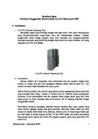
2.1 Maintenance and Operation Manual 2.1.1 Wrist Strap Connection Procedure 2-1 1. Connect the Wrist Strap to the ESD ground terminal (G).
G
Figure 2-1 ESD Ground Terminal Location
2.1.2 Maintenance Mode Setting (for the LCT Operation) Procedure 2-2 1. Click Maintenance button on the top of the LCT window. 2. Confirm that the MAINT on the top of the LCT window becomes yellow.
Maintenance Button
Figure 2-2 LCT Main Window
NWD-115477-06E
Maintenance
Submission Prohibited NEC Group Internal Use Only Precaution
2-5
3. Confirm that the MAINT LED at the front of the equipment becomes yellow. iPASOLINK 400 Main shelf
Figure 2-3 LED Location (1) MC-A4
Figure 2-4 MC-A4 Card LED Location (2) Universal Slot (a) MODEM-A/EA Card
Figure 2-5 MODEM-A/EA Card LED Location
Maintenance
NWD-115477-06E
Submission Prohibited NEC Group Internal Use Only Precaution
2-6
(b) 16E1-A Card
Figure 2-6 16E1-A Card LED Location (c) STM1-A Card
Figure 2-7 STM1-A Card LED Location (d) GbE-A Card
Figure 2-8 GbE-A Card LED Location
NWD-115477-06E
Maintenance
Submission Prohibited NEC Group Internal Use Only Precaution
2-7
(e) AUX-A Card
Figure 2-9
AUX-A Card LED Location
(f) MSE-A Card
Figure 2-10 MSE-A Card LED Location (g) PTP-A Card
Figure 2-11 PTP-A Card LED Location
(3) PS-A4 Card
Figure 2-12 PS-A4 Card LED Location
Maintenance
NWD-115477-06E
Submission Prohibited NEC Group Internal Use Only Precaution
2-8
(4) FAN-C Unit
Figure 2-13 FAN-C Unit LED Location
NWD-115477-06E
Maintenance
Submission Prohibited NEC Group Internal Use Only Precaution
2-9
2.1.3 Manual Switch Operation
iPASOLINK 400 supports the following 8 kinds of Manual Switch.
TX Switch Manual Control (Only 1+1 Hot Standby Configuration)
RX Switch Manual Control (Only 1+1 (Twin Path/Hot Standby) Configuration)
LAG Revert Control
ERP Control
RSTP / MSTP Control
SNCP Switch Control (Only SNCP Mode (E1) Configuration)
APS Switch Group Control (Only STM-1)
Timing Source Switch Control
PTP Master Source Switch Control
(1) TX Switch Manual Control Note: This item is supported when the configuration is set to 1+1 Hot Standby mode only. Ex: MODEM No.1 and No.2 are constructed as 1+1 Hot Standby mode and MODEM No.1 acts as working side. MODEM No.2 acts as standby side.
The switching procedure is as follows. Procedure 2-3 1. Click the Maintenance button on the top of the LCT window to turn on the maintenance mode. 2. Expand Maintenance Control from the LCT menu. 3. Expand Protection Control from the Maintenance Control sub menu. 4. Select MODEM TX / RX Switch Control from the Protection Control sub menu.
Maintenance
NWD-115477-06E
Submission Prohibited NEC Group Internal Use Only Precaution
2-10
5. The MODEM TX/RX Switch Control window appears. Click SW GRP No. in the TX SW Manual Control field.
Figure 2-14 MODEM TX / RX Switch Control Window 6. The MODEM TX / RX Switch Control box appears. Select Forced No.1/No.2 from the TX SW Manual Control drop-down list.
Figure 2-15 MODEM TX / RX Switch Control Box 7. Click OK button. 8. The Warning box appears. Click OK button.
Figure 2-16 Warning Box
NWD-115477-06E
Maintenance
Submission Prohibited NEC Group Internal Use Only Precaution
2-11
9. The Information box appears. Click OK button.
Figure 2-17 Information Box 10. The MODEM TX / RX Switch Control window appears again. Confirm the parameters displayed.
Figure 2-18 MODEM TX / RX Switch Control Window 11. Click the Maintenance button on the top of the LCT window to exit the maintenance mode. 12. Confirm that the MAINT color changes from yellow to white. This step ends the procedure.
(2) RX Switch Manual Control Note: This item is supported when the configuration is set to 1+1 Twin Path/Hot Standby mode only. For example, MODEM No.1 and No.2 are constructed as 1+1 Twin Path mode and MODEM No.1 acts as working side. MODEM No.2 acts as standby side.
Maintenance
NWD-115477-06E
Submission Prohibited NEC Group Internal Use Only Precaution
2-12
The switching procedure is as follows. Procedure 2-4 1. Click the Maintenance button on the top of the LCT window to turn on maintenance mode. 2. Expand Maintenance Control from the LCT menu. 3. Expand Protection Control from the Maintenance Control sub menu. 4. Select MODEM TX / RX Switch Control from the Protection Control sub menu. 5. The MODEM TX / RX Switch Control window appears. Click SW GRP No. in the RX SW Manual Control field.
Figure 2-19 MODEM TX / RX Switch Control Window 6. The MODEM TX / RX Switch Control box appears. Select Forced - No.1/2 or Manual – No.1/2 from the RX SW Manual Control drop-down list.
Figure 2-20 MODEM TX / RX Switch Control Box 7. Click OK button.
NWD-115477-06E
Maintenance
Submission Prohibited NEC Group Internal Use Only Precaution
2-13
8. The Warning box appears. Click OK button.
Figure 2-21 Warning Box 9. The Information box appears. Click OK button.
Figure 2-22 Information Box 10. The MODEM TX / RX Switch Control window appears again. Confirm the parameters displayed.
Figure 2-23 MODEM TX/RX Switch Control Window 11. Click the Maintenance button on the top of the LCT window to exit maintenance mode. 12. Confirm that the MAINT color changes from yellow to white. This step ends the procedure.
Maintenance
NWD-115477-06E
Submission Prohibited NEC Group Internal Use Only Precaution
2-14
(3) LAG Revert Control Procedure 2-5 1. Click the Maintenance button on the top of the LCT window to turn on maintenance mode. 2. Expand Maintenance Control from the LCT menu. 3. Expand Protection Control from the Maintenance Control sub menu. 4. Select LAG Revert Control from the Protection Control sub menu. 5. The LAG Revert Control window appears. Click the desired LAG to configure.
Figure 2-24 LAG Revert Control Window 6. The LAG Revert Control box appears. Click OK button.
NWD-115477-06E
Maintenance
Submission Prohibited NEC Group Internal Use Only Precaution
2-15
Figure 2-25 LAG Revert Control box 7. The Warning box appears. Click OK button.
Figure 2-26 Warning Box 8. The Information box appears. Click OK button.
Figure 2-27 Information Box 9. The LAG Revert Control window appears again. Confirm the parameters displayed.
Maintenance
NWD-115477-06E
Submission Prohibited NEC Group Internal Use Only Precaution
2-16
Figure 2-28 LAG Revert Control Window 10. Click the Maintenance button on the top of the LCT window to exit maintenance mode. 11. Confirm that the MAINT color changes from yellow to white. This step ends the procedure. (4) ERP Control Procedure 2-6 1. Expand Maintenance Control from the LCT menu. 2. Expand Protection Control from the Maintenance Control sub menu. 3. Select ERP Control from the Protection Control sub menu. 4. The ERP Control Window appears. Click the Ring ID number.
NWD-115477-06E
Maintenance
Submission Prohibited NEC Group Internal Use Only Precaution
2-17
Figure 2-29 ERP Control Window 5. The ERP Control (Loop Detection Restart) box appears. Select the Ring ID to Restart. Click Execute button.
Figure 2-30 ERP Control (Loop Detection Restart) Window 6. The ERP Control window appears again
Figure 2-31 ERP Control Window This step ends the procedure. (5) RSTP / MSTP Control Procedure 2-7 1. Click the Maintenance button on the top of the LCT window to turn on maintenance mode. 2. Expand Maintenance Control from the LCT menu. 3. Expand Protection Control from the Maintenance Control sub menu. 4. Select RSTP / MSTP Control from the Protection Control sub menu. 5. The RSTP / MSTP Control window appears. Click RSTP Clear button.
Maintenance
NWD-115477-06E
Submission Prohibited NEC Group Internal Use Only Precaution
2-18
Figure 2-32 RSTP / MSTP Control Window 6. The Warning box appears. Click OK button.
Figure 2-33 Warning Box
NWD-115477-06E
Maintenance
Submission Prohibited NEC Group Internal Use Only Precaution
2-19
7. The Information box appears. Click OK button.
Figure 2-34 Information Box 8. The RSTP / MSTP Control window appears again. Confirm the parameters displayed.
Figure 2-35 RSTP / MSTP Control Window 9. After finishing RSTP Control, click the Maintenance button on the top of the LCT window to exit maintenance mode. 10. Confirm that the MAINT color changes from yellow to white. This step ends the procedure.
Maintenance
NWD-115477-06E
Submission Prohibited NEC Group Internal Use Only Precaution
2-20
(6) SNCP Switch Control (Only SNCP Mode (E1) Configuration) Procedure 2-8 1. Click the Maintenance button on the top of the LCT window to turn on maintenance mode. 2. Expand Maintenance Control from the LCT menu. 3. Expand Protection Control from the Maintenance Control sub menu. 4. Select SNCP Switch Control from the Protection Control sub menu. 5. The SNCP Switch Control window appears. Click the desired number to configure.
Figure 2-36 SNCP Switch Control Window 6. The SNCP Switch Control box appears. Select the parameter from the SNCP Manual SW Control drop-down list.
Figure 2-37 SNCP Switch Control Box 7. Click OK button.
NWD-115477-06E
Maintenance
Submission Prohibited NEC Group Internal Use Only Precaution
2-21
8. The Warning box appears. Click OK button.
Figure 2-38 Warning Box 9. The Information box appears. Click OK button.
Figure 2-39 Information Box 10. The SNCP Switch Control window appears again. Confirm the parameters displayed.
Figure 2-40 SNCP Switch Control Window 11. Click Maintenance button on the top of the LCT window to exit maintenance mode. 12. Confirm that the MAINT color changes from yellow to white. This step ends the procedure.
Maintenance
NWD-115477-06E
Submission Prohibited NEC Group Internal Use Only Precaution
2-22
(7) APS Switch Group Control (Only STM-1) Procedure 2-9 1. Click the Maintenance button on the top of the LCT window to turn on maintenance mode. 2. Expand Maintenance Control from the LCT menu. 3. Expand Protection Control from the Maintenance Control sub menu. 4. Select APS Switch Group Control from the Protection Control sub menu. 5. The APS Switch Group Control window appears. Click the desired number to configure.
Figure 2-41
APS Switch Group Control Window
6. The APS Switch Group Control box appears. Select Manual SW to Protection or Forced SW to Protection from the APS Manual SW Control drop-down list.
Figure 2-42 SNCP Switch Control Box 7. Click OK button.
NWD-115477-06E
Maintenance
Submission Prohibited NEC Group Internal Use Only Precaution
2-23
8. The Warning box appears. Click OK button.
Figure 2-43 Warning Box 9. The Information box appears. Click OK button.
Figure 2-44 Information Box 10. The SNCP Switch Control window appears again. Confirm the parameters displayed.
Figure 2-45 SNCP Switch Control Window 11. Click the Maintenance button on the top of the LCT window to exit maintenance mode. 12. Confirm that the MAINT color changes from yellow to white. This step ends the procedure.
Maintenance
NWD-115477-06E
Submission Prohibited NEC Group Internal Use Only Precaution
2-24
(8) Timing Source Switch Control (This mode available when the Lock Out is Off only) In case that Lock Out Status is set to On, follow the Procedure 2-8 to change the setting to Off and then follow the Procedure 2-9 to configure Timing Source Switching. (a) Lock Out Setting Procedure 2-10 1. Click the Maintenance button on the top of the LCT window to turn on maintenance mode. 2. Expand Maintenance Control from the LCT menu. 3. Expand Protection Control from the Maintenance Control sub menu. 4. Select Timing Source Switch Control from the Protection Control sub menu. 5. The Timing Source Switch Control window appears. Click desired Lock Out to configure.
Figure 2-46 Timing Source Switch Control Window
NWD-115477-06E
Maintenance
Submission Prohibited NEC Group Internal Use Only Precaution
2-25
6. The Timing Source Switch Control box appears. Click Off radio button from Lock Out.
Figure 2-47 Timing Source Switch Control Box 7. Click OK button. 8. The Warning box appears. Click OK button.
Figure 2-48 Warning Box 9. The Information box appears. Click OK button.
Figure 2-49 Information Box
Maintenance
NWD-115477-06E
Submission Prohibited NEC Group Internal Use Only Precaution
2-26
10. The Timing Source Switch Control window appears again. Confirm the displayed parameters.
Figure 2-50 Timing Source Switch Control Window 11. After finishing Lock Out Setting, click the Maintenance button on the top of the LCT window to exit maintenance mode. 12. Confirm that the MAINT color changes from yellow to white. This step ends the procedure. (b) Timing Source Switch Procedure 2-11 1. Click the Maintenance button on the top of the LCT window to turn on maintenance mode. 2. Expand Maintenance Control from the LCT menu. 3. Expand Protection Control from the Maintenance Control sub menu. 4. Select Timing Source Switch Control from the Protection Control sub menu.
NWD-115477-06E
Maintenance
Submission Prohibited NEC Group Internal Use Only Precaution
2-27
5. The Timing Source Switch Control window appears. Click the desired Timing Source SW Control to configure.
Figure 2-51 Timing Source Switch Control Window 6. The Timing Source Switch Control box appears. Select switching mode (Manual SW or Forced SW).
Figure 2-52 Timing Source Switch Control Box 7. Click OK button. 8. The Warning box appears. Click OK button.
Figure 2-53 Warning Box
Maintenance
NWD-115477-06E
Submission Prohibited NEC Group Internal Use Only Precaution
2-28
9. The Information box appears. Click OK button.
Figure 2-54 Information Box 10. The Timing Source Switch Control window appears again. Confirm the displayed parameters.
Figure 2-55 Timing Source Switch Control Window 11. Click the Maintenance button on the top of the LCT window to exit maintenance mode. 12. Confirm that the MAINT color changes from yellow to white. This step ends the procedure.
NWD-115477-06E
Maintenance
Submission Prohibited NEC Group Internal Use Only Precaution
2-29
(9) PTP Master Source Switch Control (available only when PTP Lock Out is set to off) If the PTP Lock Out Status is set to On, change its setting to Off by referring to Procedure 2-12, then proceed to Procedure 2-13 to configure the PTP Timing Source Switching. (c) PTP Lock Out Setting Procedure 2-12 1. Click the Maintenance button on the top of the LCT window to turn on maintenance mode. 2. Expand Maintenance Control from the LCT menu. 3. Select PTP Domain Control from the Maintenance Control sub menu. 4. The PTP Domain Control window appears. Click desired Lock Out to configure.
Figure 2-56 PTP Domain Control Window
Maintenance
NWD-115477-06E
Submission Prohibited NEC Group Internal Use Only Precaution
2-30
5. The PTP Lock out option window appears. Click the Off radio button, then click the OK button.
Figure 2-57 PTP Lock Out Option Window 6. The Information dialog box appears. Click OK button.
Figure 2-58 Information Dialog Box
NWD-115477-06E
Maintenance
Submission Prohibited NEC Group Internal Use Only Precaution
2-31
7. The PTP Domain Control window updates the information. Confirm the displayed parameters.
Figure 2-59 PTP Domain Control Window 8. When completing the PTP Lock Out Setting, click the Maintenance button on the top of the LCT window to exit the maintenance mode. 9. Confirm that the MAINT indication color changes from yellow to white. This step ends the procedure. (d) PTP Source Switch Procedure 2-13 1. Click the Maintenance button on the top of the LCT window to turn on maintenance mode. 2. Expand Maintenance Control from the LCT menu. 3. Expand PTP Domain Control from the Maintenance Control sub menu.
Maintenance
NWD-115477-06E
Submission Prohibited NEC Group Internal Use Only Precaution
2-32
4. The PTP Domain Control window appears. Click the desired PTP SW Control to configure.
Figure 2-60 PTP Domain Control Window 5. The PTP Switch Control option window appears. Select switching mode (Normal or Forced SW).
Figure 2-61 PTP Switch Control Option Window 6. Click OK button.
NWD-115477-06E
Maintenance
Submission Prohibited NEC Group Internal Use Only Precaution
2-33
7. The Information dialog box appears. Click OK button.
Figure 2-62 Information dialog Box 8. The PTP Domain Control window updates the information. Confirm the displayed parameters.
Figure 2-63 PTP Domain Control Window 9. Click the Maintenance button on the top of the LCT window to exit maintenance mode. 10. Confirm that the MAINT color changes from yellow to white. This step ends the procedure.
Maintenance
NWD-115477-06E
Submission Prohibited NEC Group Internal Use Only Precaution
2-34/END
This page is intentionally left blank.
NWD-115477-06E
Maintenance
Submission Prohibited NEC Group Internal Use Only Current Status
3-1
3. CURRENT STATUS
3.1 Current Status The Current Status window on the LCT window is for displaying Equipment status, Line card status, Event log and all alarms detected on the equipment side. But it is just for viewing system status only you can not make any changes of all items displayed on this window. (Such as modify, adding, masking alarms or items) (1) Active Alarm Tab The Active Alarm tab displays all current alarms detected on the equipment side. You can download the current alarm list to LCT PC by clicking the Save button on the top left of the Active Alarm tab.
Figure 3-1
Maintenance
Active Alarm Tab
NWD-115477-06E
Submission Prohibited NEC Group Internal Use Only Current Status
3-2
(2) Event Log Tab The Event Log tab displays all alarms and status detected when there are any changes on the line card and configuration on equipment. You can download the Event Status list to the LCT PC by clicking the Save button on the top left of the Event Log tab.
Figure 3-2 Event Log Tab
Note: To save log list, follow the procedure below. 1. Click the Save button of the Active Alarm tab or the Event Log tab.
Figure 3-3
NWD-115477-06E
Active Alarm (or Event Log) Tab
Maintenance
Submission Prohibited NEC Group Internal Use Only Current Status
3-3
2. The File Download window appears. Click Save button.
Figure 3-4 File Download Window 3. The Save As window appears. Select the proper folder of the Local PC, and then click Save button. Default file name: Event Status: EventLog_YYYYMMDDhhmmss.log Active Alarm Status: ActiveAlarm_YYYYMMDDhhmmss.csv
Figure 3-5 Save As Window
Maintenance
NWD-115477-06E
Submission Prohibited NEC Group Internal Use Only Current Status
3-4
4. After finishing the export of log file, the Download Complete window appears. Click Close button.
Figure 3-6 Download Complete Window 5. Confirm the log file was saved in the selected folder.
Figure 3-7 Log File Folder
NWD-115477-06E
Maintenance
Submission Prohibited NEC Group Internal Use Only Current Status
3-5
(3) MODEM/ODU Tab The MODEM/ODU tab displays all alarm and status detected on MODEM card and ODU.
Figure 3-8 MODEM/ODU Tab
Maintenance
NWD-115477-06E
Submission Prohibited NEC Group Internal Use Only Current Status
3-6
(4) IDU Tab The IDU tab displays all alarms and status detected on IDU.
Figure 3-9 IDU Tab
NWD-115477-06E
Maintenance
Submission Prohibited NEC Group Internal Use Only Current Status
3-7
(5) E1 Tab (a) Main Card The E1 tab displays all alarms and status of Main Card.
Figure 3-10 E1 (Main Card) Tab
Maintenance
NWD-115477-06E
Submission Prohibited NEC Group Internal Use Only Current Status
3-8
(b) U-Slot** The E1 tab displays all alarms and status of 16E1-A.
Figure 3-11 E1 (U-Slot**) Tab
NWD-115477-06E
Maintenance
Submission Prohibited NEC Group Internal Use Only Current Status
3-9
(6) STM-1 Tab The STM-1 tab displays all alarms and status detected on STM1-A.
Figure 3-12
Maintenance
STM-1 Tab
NWD-115477-06E
Submission Prohibited NEC Group Internal Use Only Current Status
3-10
(7) GbE Tab The GbE tab displays all alarms and status detected on GbE-A.
Figure 3-13 GbE Tab
NWD-115477-06E
Maintenance
Submission Prohibited NEC Group Internal Use Only Current Status
3-11
(8) AUX Tab The AUX tab displays all alarms and status of AUX.
Figure 3-14
Maintenance
AUX Tab
NWD-115477-06E
Submission Prohibited NEC Group Internal Use Only Current Status
3-12/END
(9) MSE Tab The MSE tab displays all alarms and status of MSE-A.
Figure 3-15 MSE Tab
NWD-115477-06E
Maintenance
Submission Prohibited NEC Group Internal Use Only Current Status
3-13
(10)
PTP Tab The PTP tab displays all alarms and status of PTP-A.
Figure 3-16
Maintenance
PTP Tab
NWD-115477-06E
Submission Prohibited NEC Group Internal Use Only Current Status
3-14/END
This page is intentionally left blank.
NWD-115477-06E
Maintenance
Submission Prohibited NEC Group Internal Use Only Routine Maintenance
4-1
4. ROUTINE MAINTENANCE This chapter provides the routine (annually) maintenance procedures to ensure the satisfactory operation of the equipment. During routine maintenance, carefully observe the precautions given in Chapter 2.
4.1 Meter Reading Table 4-1 Metering Item Item
Description
TX Power
Indicates the transmit power of the ODU
RX Level
Indicates the RF reception level of the ODU
ODU Power Supply
Indicates the Power Supply voltage of the ODU
BER
Indicates the value of the BER measurement
Procedure 4-1 1. Expand Metering from the LCT menu. 2. Select Current Metering from the Metering sub menu. 3. The Current Metering window appears. Confirm the parameters displayed.
Figure 4-1 Current Metering Window
Maintenance
NWD-115477-06E
Submission Prohibited NEC Group Internal Use Only Routine Maintenance
4-2
Notes 1. If an abnormal indication appears, check Alarm/Status, performance monitor and perform loopback test to distinguish sections of normal and alarmed. 2. RX LEVEL varies depending on received RF signal level. 3. Power Supply voltage at ODU varies depending on IF cable length between the IDU and ODU.
4. Click the desired MODEM to configure. 5. The Current Metering box appears. Modify the parameter accordingly.
Figure 4-2 Current Metering Box Table 4-2 Refresh Cycle Parameter
Description
Normal Speed
Refreshed automatically every 10 seconds.
High Speed
Refreshed automatically every 3 seconds
6. Click Cancel button on the bottom of the Current Metering box. This step ends the procedure.
NWD-115477-06E
Maintenance
Submission Prohibited NEC Group Internal Use Only Routine Maintenance
4-3
4.2 Performance Monitoring The Performance Monitoring (PM) is used to identify and isolate the problem if occurring at a particular line or path. It also monitors the quality of lines and paths. All Performance Monitoring parameters are collected every minute and accumulated to 15-minute and 24-hour (1 day) statistics.
4.2.1 PM Parameters Performance Monitor Parameters can be measured from iPASOLINK. 4.2.1.1 PM Status Monitor Types Table 4-3 MODEM Performance Monitor Items Item RF BBE
Background Block
Description
Spec.
The sum of the background block error
ITU-T G.826
Error RF ES
Errored Second
The cumulative time in which more than one block error per second was detected.
ITU-T G.826
RF SES
Severely Errored
The cumulative time in which the BER of a one second period exceeded a set percentage (30%).
ITU-T G.826
The cumulative time in which the BER of a one second period exceeded 10E-3.
ITU-T G.826
Second RF SEP
Severely Errored Period
RF UAS
Unavailable Second
The cumulative time in which the unit remained inoperative
ITU-T G.826
RF OFS
Out of Frame Second
The total number of seconds the “out of frame” condition is generated in 15 minute-blocks. (OFS is applied to the Total only)
ITU-T G.826
RX LEV
RX Level
The minimum and maximum reception level (when there are two routes it does so for No. 1 and 2 respectively)
Maintenance
NWD-115477-06E
Submission Prohibited NEC Group Internal Use Only Routine Maintenance
4-4
Table 4-4 SDH/PDH Performance Monitor Items Monitor Types RS
DMR-RS
MS
E1
NWD-115477-06E
Definition
Spec.
BBE
Near end background block error
ITU-T G.826 G.784
ES
Near end errored seconds
ITU-T G.826 G.784
SES
Near end severely errored seconds
ITU-T G.826 G.784
SEP
Near end severely error period
-
UAS
Unavailable seconds
ITU-T G.826 G.784
OFS
Out of frame seconds
ITU-T G.784
BBE
Near end background block error
ITU-T G.826 G.784
ES
Near end errored seconds
ITU-T G.826 G.784
SES
Near end severely errored seconds
ITU-T G.826 G.784
SEP
Near end severely error period
-
UAS
Unavailable seconds
ITU-T G.826 G.784
OFS
Out of frame seconds
ITU-T G.784
BBE
Near end background block error
ITU-T G.826 G.784
ES
Near end errored seconds
ITU-T G.826 G.784
SES
Near end severely errored seconds
ITU-T G.826 G.784
SEP
Near end severely error period
-
UAS
Unavailable seconds
ITU-T G.826 G.784
E1 CV
Near end Code violation
Maintenance
Submission Prohibited NEC Group Internal Use Only Routine Maintenance
4-5
Table 4-5 LAN Performance Monitor Items Monitor Types
Description
Spec.
RX Octs
The total number of octets received on the interface, including framing characters.
RFC2819
TX Octs
The total number of octets transmitted out of the interface, including framing characters.
RFC2819
RX Pkts
Number of packets received (including bad packets, all Unicast, Broadcast packets, and Multicast packets)
RFC2819
TX Pkts
The total number of packets transmitted.
RFC2819
RX Drop Events
A count of drop packets
RFC2819
RX Undersize Pkts
Number of packets received that were less than 64 octets long and were otherwise well formed
RFC2819
RX Fragments
Number of error frames of less than 64 octets in transmission data length
RFC2819
RX 64Octs
Number of packets received that were between 64 octets in length(including error packets)
RFC2819
TX 64Octs
Number of packets transmitted 64 octets in length (including error packets)
RFC2819
RX 65 to 127Octs
Number of packets received that were between 65 to 127 octets in length (including error packets)
RFC2819
TX 65 to 127Octs
Number of packets transmitted and received that were between 65 to 127 octets in length (including error packets)
RFC2819
RX 128 to 255Octs
Number of packets received that were between 128 to 255 octets in length (including error packets)
RFC2819
TX 128 to 255Octs
Number of packets transmitted and received that were between 128 to 255 octets in length (including error packets)
RFC2819
RX 256 to 511Octs
Number of packets received that were between 256 to 511 octets in length (including error packets)
RFC2819
TX 256 to 511Octs
Number of packets transmitted and received that were between 256 to 511 octets in length (including error packets)
RFC2819
RX 512 to 1023Octs
Number of packets received that were between 512 to 1023 octets in length (including error packets)
RFC2819
TX 512 to 1023Octs
Number of packets transmitted and received that were between 512 to 1023 octets in length (including error packets)
RFC2819
RX 1024 to 1518Octs
Number of packets received that were between 1023 to 1518 octets in length (including error packets)
RFC2819
TX 1024 to 1518Octs
Number of packets transmitted and received that were between 1024 to 1518 octets in length (including error packets)
RFC2819
RX CRC Alignment Errors
Number of reception alignments of FCS error frames
RFC2819
RX Oversize Pkts
A count of frames received on a particular interface that exceeds maximum size bytes.
RFC2819
Maintenance
NWD-115477-06E
Submission Prohibited NEC Group Internal Use Only Routine Maintenance
4-6
Monitor Types
Description
Spec.
RX Jabbers
Number of error frames more than 1519 octets in receive data length
RFC2819
RX Multicast Pkts
Number of good multicast packets received (excluding broadcast packets)
RFC2819
TX Multicast Pkts
The total number packets that higher-level protocols requested to be transmitted to a multicast address.
RFC2819
RX Broadcast Pkts
Number of good broadcast packets received
RFC2819
TX Broadcast Pkts
The total number packets that higher-level protocols requested to be transmitted to a broadcast address.
RFC2819
TX Collisions
Number of collisions on this ETH segment
RFC2819
RX Unknown TPID
Number of abandoned frames included in unsetting TPID frames received, or number of abandoned frames with Broadcast Storm Control function
RX Unknown VID
Number of abandoned frames included in unsetting VID frames received
RX MAC Limit
Number of frames discarded due to exceeding MAC learning Limit
RX Filter Discard
Number of frames abandoned by input filtering function
RX QoS Discard
Number of frames abandoned by Policing function of input port
TX Queue0 Discard
Number of QoS frames discard by transmission Queue0
TX Queue1 Discard
Number of QoS frames discard by transmission Queue1
TX Queue2 Discard
Number of QoS frames discard by transmission Queue2
TX Queue3 Discard
Number of QoS frames discard by transmission Queue3
Per VLAN Rx Frames
Number of frames received as particular VLAN
Per VLAN Tx Frames
Number of frames transmitted as particular VLAN
Per VLAN Rx QoS Discard
Number of discarded frames per VLAN basis.
Table 4-6 MODEM PM Counter Range PM Types
15M PM Counter Range
24h PM Counter Range
RF OFS
0 to 900
0 to 86400
RF BBE
It depends on radio setting (CS and Modulation)
It depends on radio setting (CS and Modulation)
RF ES
0 to 900
0 to 86400
RF SES
0 to 900
0 to 86400
RF SEP
0 to 900
0 to 86400
RF UAS
0 to 900
0 to 86400
NWD-115477-06E
Maintenance
Submission Prohibited NEC Group Internal Use Only Routine Maintenance
4-7
Table 4-7 SDH/PDH PM Counter Range PM Types
15M PM Counter Range
24h PM Counter Range
OFS
0 to 900
0 to 86400
BBE
0 to 16777215
0 to 1610612640
ES
0 to 900
0 to 86400
SES
0 to 900
0 to 86400
SEP
0 to 900
0 to 86400
UAS
0 to 900
0 to 86400
0 to 4294967295
0 to 4294967295
E1 CV
Table 4-8 LAN PM Counter Range PM Types
15M PM Counter Range
24h PM Counter Range
RX Octs
0 to 18446744073709551615
0 to 18446744073709551615
TX Octs
0 to 18446744073709551615
0 to 18446744073709551615
RX Pkts
0 to 4294967295
0 to 4294967295
TX Pkts
0 to 4294967295
0 to 4294967295
RX Drop Events
0 to 4294967295
0 to 4294967295
RX Undersize Pkts
0 to 4294967295
0 to 4294967295
RX Fragments
0 to 4294967295
0 to 4294967295
RX 64Octs
0 to 4294967295
0 to 4294967295
TX 64Octs
0 to 4294967295
0 to 4294967295
RX 65 to 127Octs
0 to 4294967295
0 to 4294967295
TX 65 to 127Octs
0 to 4294967295
0 to 4294967295
RX 128 to 255Octs
0 to 4294967295
0 to 4294967295
TX 128 to 255Octs
0 to 4294967295
0 to 4294967295
RX 256 to 511Octs
0 to 4294967295
0 to 4294967295
TX 256 to 511Octs
0 to 4294967295
0 to 4294967295
RX 512 to 1023Octs
0 to 4294967295
0 to 4294967295
TX 512 to 1023Octs
0 to 4294967295
0 to 4294967295
RX 1024 to 1518Octs
0 to 4294967295
0 to 4294967295
TX 1024 to 1518Octs
0 to 4294967295
0 to 4294967295
RX CRC Alignment Errors
0 to 4294967295
0 to 4294967295
TX Oversize Pkts
0 to 4294967295
0 to 4294967295
RX Oversize Pkts
0 to 4294967295
0 to 4294967295
RX Jabbers
0 to 4294967295
0 to 4294967295
RX Multicast Pkts
0 to 4294967295
0 to 4294967295
TX Multicast Pkts
0 to 4294967295
0 to 4294967295
Maintenance
NWD-115477-06E
Submission Prohibited NEC Group Internal Use Only Routine Maintenance
4-8
PM Types
15M PM Counter Range
24h PM Counter Range
RX Broadcast Pkts
0 to 4294967295
0 to 4294967295
TX Broadcast Pkts
0 to 4294967295
0 to 4294967295
TX Collisions
0 to 4294967295
0 to 4294967295
RX Unknown TPID
0 to 18446744073709551615
0 to 18446744073709551615
RX Unknown VID
0 to 18446744073709551615
0 to 18446744073709551615
RX MAC Limit
0 to 18446744073709551615
0 to 18446744073709551615
RX Filter Discard
0 to 18446744073709551615
0 to 18446744073709551615
RX QoS Discard
0 to 18446744073709551615
0 to 18446744073709551615
TX Queue0 Discard
0 to 18446744073709551615
0 to 18446744073709551615
TX Queue1 Discard
0 to 18446744073709551615
0 to 18446744073709551615
TX Queue2 Discard
0 to 18446744073709551615
0 to 18446744073709551615
TX Queue3 Discard
0 to 18446744073709551615
0 to 18446744073709551615
Per VLAN Rx Frames
0 to 18446744073709551615
0 to 18446744073709551615
Per VLAN Tx Frames
0 to 18446744073709551615
0 to 18446744073709551615
Per VLAN Rx QoS Discard
0 to 18446744073709551615
0 to 18446744073709551615
Table 4-9 MODEM TCA Threshold PM Types
RF OFS RF BBE
15min TCA Threshold Range
1 to 900
24h TCA Threshold
Default threshold Occur
Recovery
900
90
It depends on radio setting (CS and Modulation)
Range
1 to 86400
Default threshold Occur
Recovery
65534
650
It depends on radio setting (CS and Modulation)
RF ES
1 to 900
900
90
1 to 86400
65534
650
RF SES
1 to 900
900
90
1 to 86400
65534
650
RF SEP
1 to 900
900
90
1 to 86400
65534
650
900
90
1 to 86400
65534
650
RF UAS
1 to 900
RX LEV
-99 to -30
It depends on radio setting (CS and Modulation)
NWD-115477-06E
-99 to -30
It depends on radio setting (CS and Modulation)
Maintenance
Submission Prohibited NEC Group Internal Use Only Routine Maintenance
4-9
Table 4-10 MODEM RX LEV TCA default Threshold Modulation Type
CS=7 MHz
CS=14 MHz
CS=28 MHz
CS=56 MHz
QPSK
-98 dBm
-95 dBm
-92 dBm
-89 dBm
16QAM
-92 dBm
-89 dBm
-86 dBm
-83 dBm
32QAM
-89 dBm
-86 dBm
-83 dBm
-80 dBm
64QAM
-86 dBm
-83 dBm
-80 dBm
-77 dBm
128QAM
-83 dBm
-80 dBm
-77 dBm
-74 dBm
256QAM
-80 dBm
-77 dBm
-74 dBm
-71 dBm
Table 4-11 MODEM RF BBE TCA Threshold Modulation Types CS
7M
14M
28M
56M
Maintenance
Modulation
15min TCA Threshold Range
24h TCA Threshold
Default threshold Occur
Recovery
Range
Default threshold Occur
Recovery
QPSK
1-805000
8,050
805
1-77280000
772,800
77,280
16QAM
1-1611000
16,110
1,611
1-154656000
1,546,560
154,656
32QAM
1-2014000
20,140
2,014
1-193344000
1,933,440
193,344
64QAM
1-2417000
24,170
2,417
1-232032000
2,320,320
232,032
128QAM
1-2820000
28,200
2,820
1-270720000
2,707,200
270,720
256QAM
1-3223000
32,230
3,223
1-309408000
3,094,080
309,408
QPSK
1-1611000
16,110
1,611
1-154656000
1,546,560
154,656
16QAM
1-3223000
32,230
3,223
1-309408000
3,094,080
309,408
32QAM
1-4028000
40,280
4,028
1-386688000
3,866,880
386,688
64QAM
1-4834000
48,340
4,834
1-464064000
4,640,640
464,064
128QAM
1-5640000
56,400
5,640
1-541440000
5,414,400
541,440
256QAM
1-6446000
64,460
6,446
1-618816000
6,188,160
618,816
NWD-115477-06E
Submission Prohibited NEC Group Internal Use Only Routine Maintenance
4-10
Table 4-12 SDH/PDH TCA Threshold PM Types
15min TCA Threshold Range
24h TCA Threshold
Default threshold Occur
Recovery
Range
Default threshold Occur
Recovery
RS OFS
1 to 900
900
90
1 to 86400
65534
650
RS BBE
1 to 16777215
65534
6560
1 to 1610612640
6291260
629130
RS ES
1 to 900
900
90
1 to 86400
65534
650
RS SES
1 to 900
900
90
1 to 86400
65534
650
RS SEP
1 to 900
900
90
1 to 86400
65534
650
RS UAS
1 to 900
900
90
1 to 86400
65534
650
DMR RS
1 to 900
900
90
1 to 86400
65534
650
1 to 16777215
65534
6560
1 to 1610612640
6291260
629130
1 to 900
900
90
1 to 86400
65534
650
1 to 900
900
90
1 to 86400
65534
650
1 to 900
900
90
1 to 86400
65534
650
1 to 900
900
90
1 to 86400
65534
650
1 to 16777215
65534
6560
1 to 1610612640
6291260
629130
MS ES
1 to 900
900
90
1 to 86400
65534
650
MS SES
1 to 900
900
90
1 to 86400
65534
650
MS SEP
1 to 900
900
90
1 to 86400
65534
650
MS UAS
1 to 900
900
90
1 to 86400
65534
650
1 to
65534
650
1 to 4294967295
6291260
629130
OFS DMR RS BBE DMR RS ES DMR RS SES DMR RS SEP DMR RS UAS MS BBE
E1 CV
4294967295
NWD-115477-06E
Maintenance
Submission Prohibited NEC Group Internal Use Only Routine Maintenance
4-11
Table 4-13 LAN TCA Threshold PM Types
15min TCA Threshold
24h TCA Threshold
Range
Default threshold
Range
Default threshold
Drop Event
1 to 133929000
133929000
1 to 4294967295
4294967295
Undersize Packets
1 to 133929000
133929000
1 to 4294967295
4294967295
Fragment Packets
1 to 133929000
133929000
1 to 4294967295
4294967295
CRC Alignment
1 to 133929000
133929000
1 to 4294967295
4294967295
Oversize Packets
1 to 133929000
133929000
1 to 4294967295
4294967295
Collisions
1 to 133929000
133929000
1 to 4294967295
4294967295
Error
Maintenance
NWD-115477-06E
Submission Prohibited NEC Group Internal Use Only Routine Maintenance
4-12/END
This page is intentionally left blank.
NWD-115477-06E
Maintenance
Submission Prohibited NEC Group Internal Use Only Corrective Maintenance
5-1
5. CORRECTIVE MAINTENANCE Corrective maintenance done in the field is described in this chapter. Corrective maintenance in the field covers fault isolation, card/unit replacement and alignment. The fault location procedures describe how to isolate card-level/unit-level faults. Faults can be classified in to those that cause deterioration of the transmission quality and those that interrupt the traffic due to a malfunction of the equipment. This chapter explains the troubleshooting procedures for equipment faults and the corresponding remedial methods. The purpose of troubleshooting malfunctioning equipment is to restart the service by locating the faulty part and replacing it with a spare. The faults that cause deterioration quality are primarily originated by changes occurred in the state of propagation. Therefore, if a decline in the transmission quality or similar fakes place frequently, the link design will have to be reviewed. During the corrective maintenance, carefully observe the precautions given in Chapter2, until the alignment is completed.
Maintenance
NWD-115477-06E
Submission Prohibited NEC Group Internal Use Only Corrective Maintenance
5-2
5.1 Alarm/Status When an alarm event has occurred, at first, check alarm indication on the front of the IDU. Continuously, connect the PC to the LOCAL jack on the LCT port mounted on the IDU and check alarm/status indication. A faulty part can be located by checking the alarm LED indications and LCT Alarm indications. Alarm Report When an alarm is detected, alarm notification is made to the user by lighting up the LEDs on the rack, and reporting the alarm to user interface. The alarm notification is also made to the user by an Office alarm, such as the station alarm bell and lamps.
ALARM LED indication LED at the front of the rack lights up/turn off when alarm is generated/cleared to report the alarm to the user. iPASOLINK 400 Main shelf
Figure 5-1 LED Location (1) MC-A4
Figure 5-2 MC-A4 Card LED Location
NWD-115477-06E
Maintenance
Submission Prohibited NEC Group Internal Use Only Corrective Maintenance
5-3
(2) Universal Slot (a) MODEM-A/EA Card
Figure 5-3 MODEM-A/EA Card LED Location (b) 16E1-A Card
Figure 5-4 16E1-A Card LED Location (c) STM1-A Card
Figure 5-5 STM1-A Card LED Location
Maintenance
NWD-115477-06E
Submission Prohibited NEC Group Internal Use Only Corrective Maintenance
5-4
(d) GbE-A Card
Figure 5-6 GbE-A Card LED Location (e) AUX-A Card
Figure 5-7
AUX-A Card LED Location
(f) MSE-A Card
Figure 5-8 MSE-A Card LED Location (g) PTP-A Card
Figure 5-9 PTP-A Card LED Location
NWD-115477-06E
Maintenance
Submission Prohibited NEC Group Internal Use Only Corrective Maintenance
5-5
(3) PS-A4 Card
Figure 5-10 PS-A4 Card LED Location (4) FAN-C Unit
Figure 5-11 FAN-C Unit LED Location
Maintenance
NWD-115477-06E
Submission Prohibited NEC Group Internal Use Only Corrective Maintenance
5-6
Web-LCT indication The alarm LED indications and PNMT indication faulty part can be located by checking the ALM LED indicators and Web-LCT Alarm indications.
Figure 5-12
Active Status (Current Status) Window
Meter Reading Based on the meter readings during periodical inspection with LCT in Chapter 5, a faulty part can be located by checking if the reading values exceed the permissible ranges. Loopback In case of an abnormal BER measurement result among the meter reading items, try to distinguish the faulty part by Loopback procedure.
NWD-115477-06E
Maintenance
Submission Prohibited NEC Group Internal Use Only Corrective Maintenance
5-7
5.1.1 Alarm Management
The alarm severity of each failure is indicated by the following alarm level and alarm class. Alarm classes can be modified. Modification is done by Alarm Severity Setting. 5.1.1.1 Alarm Class Critical (CR) : The Critical severity level indicates that a service affecting condition has occurred and an immediate corrective action is required. Such a severity can be reported, for example, when a managed object becomes totally out of service and its capability must be restored. Major (MJ): The Major severity level indicates that a service affecting condition has developed and an urgent corrective action is required. Such a severity can be reported, for example, when there is a severe degradation in the capability of the managed object and its full capability must be restored. Minor (MN): The Minor severity level indicates the existence of a non-service affecting fault condition and that corrective action should be taken in order to prevent a more serious (for example, service affecting) fault. Such a severity can be reported, for example, when the detected alarm condition is not currently degrading the capacity of the managed object. Warning (WR): The Warning severity level indicates the detection of a potential or impending service affecting fault, before any significant effects have been felt. Action should be taken to further diagnose (if necessary) and correct the problem in order to prevent it from becoming a more serious service affecting fault.
Maintenance
NWD-115477-06E
Submission Prohibited NEC Group Internal Use Only Corrective Maintenance
5-8
5.1.2 Alarm and Status Indication Detail 5.1.2.1 ODU Alarms & Status Indication
Category
Descriptions
Severity
ODU Alarm
Alarm
ODU hardware failure.
MJ
TX Power
Alarm
The TX PWR is lower than 3 dB.
MJ
TX Input
Alarm
The TX IF signal become out of range from -29 dBm ± 5 dB.
MJ
RX Level
Alarm
The reception level becomes lower than -72 dBm ~ -94 dBm level. (It depends on the modulation system and bit rates).
MJ
ODU CPU / Cable Open
Alarm
CPU of ODU is faulty or IF CABLE between IDU and ODU is broken or is not connected.
MJ
Mute Status
Status
Indicates the control status of the ODU TX power output. When the TX power is set to Mute, Status is issued.
-
LO REF
Alarm
Loss of Ref LO signal of ODU.
MN
ODU TYPE MISMATCH
Alarm
Indicate connected ODU type is not supported at iPASOLINK system, or ODU type cannot use in provisioned modulation setting.
MJ
ODU Power Supply
Alarm
ALM in a case of Power supply interruption to ODU.
MJ
NWD-115477-06E
Maintenance
Submission Prohibited NEC Group Internal Use Only Corrective Maintenance
5-9
5.1.2.2 MODEM-A/EA Alarms & Status Indication
Category
Descriptions
Severity
Unequipped
Alarm
Reserved and installed optional card is removed from optional slot.
MJ
Type Mismatch
Alarm
The equipped type of interface is different from configured type.
MJ
Communication FAIL
Alarm
Communication failure of equipment internal control communication.
MJ
Module
Alarm
Equipment fault
MJ
Tx Bus Error
Alarm
Data communication BUS failure condition in TX direction from MODEM-A/EA Card.
MJ
Rx Bus Error
Alarm
Data communication BUS failure condition in RX direction from MODEM-A/EA Card.
MJ
RX SW Status
Status
Radio interface RX SW usage state in Redundant configuration
-
TX SW Status
Status
Radio interface TX SW usage state in Redundant configuration
-
LOF
Alarm
Loss of Frame at radio side.
MJ
Frame ID
Alarm
Frame ID (route differentiation ID)
MJ
High BER
Alarm
Radio signal degradation (High BER threshold detection). (Threshold :1E-3/1E-4/1E-5)
MJ
Low BER
Alarm
Radio signal degradation (Low BER threshold detection). (Threshold. :1E-6/1E-7/1E-8/1E-9)
MN
Early Warning
Alarm
Radio signal degradation (Early Warning threshold detection). (Threshold :1E-9)
MN
MOD
Alarm
Indicates the operating status of the MOD. When any failure occurs in the modulator section, “Alarm” is issued.
MJ
IF Cable Short
Alarm
IF cable between IDU - ODU is in short condition.
MJ
XIF
Alarm
XIF cable connection error between XPIC master and slave MODEM cards
MJ
InPhase
Status
In - Phase indicates the received signal DADE status between No.1 and No.2 MODEM interfaces are in Phase condition. In this condition, hitless switch over is available.
-
L2SYNC Loss
Alarm
Loss of frame synchronization of GFP frames on MODEM port.
MJ
RDI
Alarm
RDI indication reception alarm on MODEM port
WR
UAE
Alarm
UAE alarm. Indicates the occurrence of an Unavailable state.
WR
XPIC Mode Mismatch
Alarm
XPIC configuration of two MODEMs is not configured as Master-Slave.
MJ
Maintenance
NWD-115477-06E
Submission Prohibited NEC Group Internal Use Only Corrective Maintenance
5-10
Indication
Category
Descriptions
Severity
TDM / AMR Range Mismatch
Alarm
Mismatch condition when the mapping number of E1 channels are different between TX and RX modem ports or mismatch condition of selected RX AMR modulation range and TX AMR modulation range.
MJ
ATPC Power Mode
Status
ATPC control signal fault (90sec) as well as MAX Power continuation 90sec.
-
TX SW Reverse Request
Status
TXSW request signal receiving condition from the opposite station:
-
TX SW Lock-in Status
Status
TXSW Lockin state
-
Unlocked
Alarm
Wireless synchronization status of the local side.
MJ
MODEM Power Supply Alarm
Alarm
Indicate power off condition of power switch which is in front of MODEM-A/EA card.
MJ
Compression Setting Mismatch
Alarm
Header Compression Mode of two opposite MODEMs are not configured as the same mode.
MJ
5.1.2.3
STM1-A Option Card Alarms & Status
Indication
Category
Descriptions
Severity
Unequipped
Alarm
Reserved and installed optional card is removed from optional slot.
MJ
Type Mismatch
Alarm
The equipped type of interface is different from configured type.
MJ
Communication FAIL
Alarm
Communication failure of equipment internal control communication.
MJ
Module
Alarm
Equipment fault
MJ
Tx Bus Error
Alarm
Data communication BUS failure condition in TX direction from STM1-A Card.
MJ
Rx Bus Error
Alarm
Data communication BUS failure condition in RX direction from STM1-A Card.
MJ
APS Online Status
Status
APS line protection online status indication
-
SFP Type Mismatch
Alarm
Mismatch between SFP on LCT and installed SFP.
MJ
SFP Removed
Alarm
A SFP is removed.
MJ
STM-1 LOS
Alarm
LOS detection on STM-1 Optical port.
MJ
TF
Alarm
Transmit Failure detection on STM-1 optical port.
MJ
RS LOF
Alarm
SDH Frame synchronization lost in RS (Regenerator Section) on STM-1 port.
MJ
RS TIM
Alarm
Trace Identifier Mismatch detected in RS (Regenerator Section) on STM-1 port.
MJ
NWD-115477-06E
Maintenance
Submission Prohibited NEC Group Internal Use Only Corrective Maintenance
5-11
Indication
Category
Descriptions
Severity
RS EXC
Alarm
B1 Byte error occurrence in RS (Regenerator Section) on STM-1 port.
MJ
RS DEG
Alarm
B1 byte error in RS (Regenerator Section) (RS Degraded) on STM-1 port.
MN
MS AIS
Alarm
AIS detection in MS (Multiplex Section) on STM-1 port.
MJ
MS RDI
Alarm
Remote Defect Indication reception in MS (Multiplex Section) on STM-1 port.
MJ
AU AIS
Alarm
AIS detection in AU (Administrative Unit) on STM-1 port.
MJ
AU LOP
Alarm
Loss of AU pointer happens on STM-1 port.
MJ
HP UNEQ
Alarm
HOP (Higher Order Path) Unequipped occurrence on STM-1 port.
MJ
HP TIM
Alarm
HOP (Higher Order Path) Trace Identifier mismatch occurrence on STM-1 port.
MJ
HP PLM
Alarm
Payload Label Mismatch occurrence in HOP (Higher Order Path) on STM-1 port.
MJ
HP RDI
Alarm
RDI (Remote Defect Indication) reception in HOP (Higher Order Path) on STM-1 port.
MJ
LOM
Alarm
Loss of Multi-Frame on STM-1 port.
MJ
TU AIS
Alarm
In TU (Tributary Unit), AIS detection on STM-1 port.
MJ
TU LOP
Alarm
Loss of TU Pointer on STM-1 port.
MJ
LP UNEQ.
Alarm
LP (Lower Order Path) Unequipped occurrence on STM-1 port.
MJ
LP RDI
Alarm
Remote Defect Indicate reception by an LP (Lower Order Path) on STM-1 port.
MJ
LP PLM
Alarm
Payload Label Mismatch Failure occurrence by an LP (Lower Order Path) on STM-1 port.
MJ
ALS
Status
Indication of automatic laser shutdown condition at STM-1 optical port.
-
RS UAS Status
Status
UAS status indication on STM port (Repeater Section)
-
STM-1 AIS Generated
Status
AIS generation condition on STM port.
-
PJE
Status
Pointer justification Event indication at STM port.
-
Maintenance
NWD-115477-06E
Submission Prohibited NEC Group Internal Use Only Corrective Maintenance
5-12
5.1.2.4 16E1-A Option Card Alarms & Status Indication
Category
Descriptions
Severity
Unequipped
Alarm
Reserved and installed optional card is removed from optional slot.
MJ
Type Mismatch
Alarm
The equipped type of interface is different from configured type.
MJ
Communication FAIL
Alarm
Communication failure of equipment internal control communication.
MJ
Module
Alarm
Equipment fault
MJ
Tx Bus Error
Alarm
Data communication BUS failure condition in TX direction from 16E1-A Card.
MJ
Rx Bus Error
Alarm
Data communication BUS failure condition in RX direction from 16E1-ACard.
MJ
E1 LOS
Alarm
No signal input on E1 port
MJ
E1 AIS
Alarm /
PDH – AIS
MJ / -
Status
ALARM/Status category can change according to " AIS Received Condition Setting
Usage Error
Alarm
Unused E1 CH input signal detection.
MN
E1 AIS Generated
Status
AIS generation condition on every E1 Channels.
-
5.1.2.5 AUX-A Option Card Alarms & Status Indication
Category
Descriptions
Severity
Unequipped
Alarm
Reserved and installed optional card is removed from optional slot.
MJ
Type Mismatch
Alarm
The equipped type of interface is different from configured type.
MJ
Communication FAIL
Alarm
Communication failure of equipment internal control communication.
MJ
Module
Alarm
Equipment fault
MJ
Tx Bus Error
Alarm
Data communication BUS failure condition in TX direction from AUX-A Card.
MJ
Rx Bus Error
Alarm
Data communication BUS failure condition in RX direction from AUX-A Card.
MJ
Item Name (Input-x)
Status/
Item Name (Cluster-x)
Alarm
HKA Status Indication {Alarm, Normal} for every HKA input.
- or Severity selectable
Item Name (Output-x)
Status
HKC Status {Alarm, Normal} for every HKC output.
-
NWD-115477-06E
Maintenance
Submission Prohibited NEC Group Internal Use Only Corrective Maintenance
5-13
5.1.2.6 GbE-A Option Card Alarms & Status Indication
Category
Descriptions
Severity
Unequipped
Alarm
Reserved and installed optional card is removed from optional slot.
MJ
Type Mismatch
Alarm
The equipped type of interface is different from configured type.
MJ
Communication FAIL
Alarm
Communication failure of equipment internal control communication.
MJ
Module
Alarm
Equipment fault
MJ
Tx Bus Error
Alarm
Data communication BUS failure condition in TX direction from GbE-A Card.
MJ
Rx Bus Error
Alarm
Data communication BUS failure condition in RX direction from GbE-A Card.
MJ
SFP Type Mismatch
Alarm
Mismatch between SFP on LCT and installed SFP.
MJ
SFP Removed
Alarm
A SFP is removed.
MJ
ETH LOS
Alarm
LOS detection at Optical ETH port.
MJ
ETH TF
Alarm
Transmit Fail detection at Optical ETH port.
MJ
LAN LINK
Alarm
LINK of the LAN Port is disconnected.
MJ
Speed & Duplex
Status
LAN Port setting (Speed&Duplex)
-
5.1.2.7 MSE-A Option Card Alarms & Status Indication
Category
Descriptions
Severity
Unequipped
Alarm
Reserved and installed optional card is removed from optional slot.
MJ
Type Mismatch
Alarm
The equipped type of interface is different from configured type.
MJ
Communication FAIL
Alarm
Communication failure of equipment internal control communication.
MJ
Module
Alarm
Equipment fault
MJ
Tx Bus Error
Alarm
Data communication BUS failure condition in TX direction from MSE-A Card.
MJ
Rx Bus Error
Alarm
Data communication BUS failure condition in RX direction from MSE-A Card.
MJ
TDM Buffer Underrun
Alarm
When packets at Ether side of the PWE path are not received or a problem occurs with received packets.
MJ
Adaptive CLK Status
Status
Outputs when the adaptive clock state has changed.
-
(Acquired, Acquiring, Holdover)
Maintenance
NWD-115477-06E
Submission Prohibited NEC Group Internal Use Only Corrective Maintenance
5-14
5.1.2.8
PTP-A Option Card Alarms & Status
Indication
Category
Descriptions
Severity
Unequipped
Alarm
Reserved and installed optional card is removed from optional slot.
MJ
Type Mismatch
Alarm
The equipped type of interface is different from configured type.
MJ
Communication FAIL
Alarm
Communication failure of equipment internal control communication.
MJ
Module
Alarm
Equipment fault
MJ
Tx Bus Error
Alarm
Data communication BUS failure condition in TX direction from PTP-A Card.
MJ
Rx Bus Error
Alarm
Data communication BUS failure condition in RX direction from PTP-A Card.
MJ
PTP CLK FAIL
Alarm
Abnormal temperature or internal oscillator failure occurs in PTP-A Card.
MJ
Loss Sync
Alarm
Sync packets are lost in communication between PTP-A and Grandmaster.
MJ
Loss Announce
Alarm
Announce packets are lost in communication between PTP-A and Master.
MJ
Unusable
Alarm
PDV in communication between PTP-A and Master is found to be large, or the delay asymmetry in the network is changed.
MJ
Clock Status
Status
Indicates the status of Frequency / Time Synchronization on PTP-A Card.
-
Grandmaster / Port ID
Status
Indicates the Port ID of the opposing equipment connected with the Grandmaster (Top-level master) to which the target PTP-A belongs.
-
Grandmaster / Clock ID
Status
Indicates the Clock ID of Grandmaster (Top-level master) to which the target PTP-A belongs.
-
Grandmaster
Status
Indicates the Clock Priority1 of Grandmaster (Top-level master) to which the target PTP-A belongs.
-
Status
Indicates the Clock Priority2 of Grandmaster (Top-level master) to which the target PTP-A belongs.
-
Status
Indicates the Clock Quality Class of Grandmaster (Top-level master) to which the target PTP-A belongs.
-
Status
Indicates the Clock Quality Accuracy of Grandmaster (Top-level master) to which the target PTP-A belongs.
-
Status
Indicates the Offset Scaled Log Variance of Grandmaster (Top-level master) to which the target PTP-A belongs.
-
/ Clock Priority1 Grandmaster / Clock Priority2 Grandmaster / Clock Quality Class Grandmaster / Clock Quality Accuracy Grandmaster / Offset Scaled Log Variance
NWD-115477-06E
Maintenance
Submission Prohibited NEC Group Internal Use Only Corrective Maintenance
5-15
Indication
Category
Descriptions
Severity
Current Role
Status
Indicates the current port roles of PTP-A logical ports.
-
Current Status
Status
Indicates the current port status of PTP-A logical ports.
-
Current TX mode
Status
Indicates the current port TX Transmission modes of PTP-A logical ports.
-
Current RX mode
Status
Indicates the current port RX Transmission modes of PTP-A logical ports.
-
Clock ID
Status
Indicates the clock ID of opposing node.
-
Clock Class
Status
Indicates the clock class of opposing node.
-
PTP Source Status
Status
Indicates whether or not the opposing equipment connected with the target port on PTP-A is assigned as Master.
-
Slave Associated Status
Status
Indicates the status of subordinate slaves when in the Unicast/BC mode.
-
Slave Associated Port
Status
Indicates the physical port number of Subordinate slaves when in the Unicast/BC mode.
-
Slave Associated Port No.
Status
Indicates the logical port number of Subordinate slaves when in the Unicast/BC mode.
-
5.1.2.9 MC-A4 Alarms & Status Indication
Category
Descriptions
Severity
Module
Alarm
Equipment fault
MJ
Bus Error
Alarm
Data communication BUS failure condition.
MJ
Unequipped (PS)
Alarm
Installed Power Supply Card is removed from PS slot.
MJ
Power Supply(PS)
Alarm
Alarm in case of power failure.
MJ
FAN FAIL
Alarm
FAN failure
MJ
Unequipped (FAN)
Alarm
Installed FAN Unit is removed from FAN slot.
MJ
EXT CLK Unequipped
Alarm
Installed CLK2M Module is removed from Main Card.
MJ
EXT CLK Type Mismatch
Alarm
The equipped type of interface is different from configured type.
MJ
IDU CPU Alarm
Alarm.
IDU CPU Alarm
MN
Memory FAIL
Alarm
Detection of memory failure
MJ
USB FAIL
Alarm
USB memory failure indication
WR
Temperature
Alarm
The temperature is over the threshold
MJ
Maintenance
Status
Maintenance declaration.
-
CLK FAIL
Alarm
Reference Clock Failed.
MN
CLK Drift
Alarm
Reference Clock source Frequency drift condition
MN
LTI
Alarm
Loss of all incoming timing source
MJ
Maintenance
NWD-115477-06E
Submission Prohibited NEC Group Internal Use Only Corrective Maintenance
5-16
Indication
Category
Descriptions
Severity
CLK Status Changed
Status
Reference clock change status
-
(1) (Locked Ref1) (2) (Locked Ref2) (3) (Locked Ref3) (4) Holdover (5) Freerun SSM FAIL
Alarm
Received Sync Status Message value is in unstable condition.
MN
Squelch
Status
The condition of External CLK Output is in squelch condition.
-
EXT CLK LOS
Alarm
Loss of Signal condition of External clock input.
MN
EXT CLK AIS
Alarm
AIS (Alarm Indication Signal) condition of External Clock input.
MN
EXT CLK LOF
Alarm
Loss of frame condition of External Clock input.
MN
EXT CLK Loop
Alarm
Indication of EXTERNAL clock input is used as EXTERNAL clock output.
MJ
E1 LOS
Alarm
No signal input on E1 port
MJ
E1 AIS
Alarm /
PDH – AIS
MJ / -
Status
ALARM/Status category can change according to " AIS Received Condition Setting
PPS FAIL
Alarm
E1 SNCP Path Protection Switch failed
MJ
Usage Error
Alarm
Unused E1 CH input signal detection.
MN
E1 AIS Generated
Status
AIS generation condition on every E1 Channels.
-
ETH LOS
Alarm
LOS detection at Optical ETH port.
MJ
ETH TF
Alarm
Transmit Fail detection at Optical ETH port.
MJ
SFP Type Mismatch (ETH)
Alarm
Mismatch between SFP on LCT and installed SFP.
MJ
SFP Removed (ETH)
Alarm
A SFP is removed.
MJ
LAN LINK
Alarm
LINK of the LAN Port is disconnected.
MJ
Speed & Duplex
Status
LAN Port setting (Speed&Duplex)
-
ETH-OAM LOC
Alarm
ETH OAM LOC ( Loss of connectivity) is detected on the indicated MEP
MJ
ETH-OAM Mismerge
Alarm
ETH OAM Mismatch detection notice.
MN
ETH-OAM Unexpected MEP
Alarm
ETH OAM Unexpected MEP and Ether OAM Unexpected Period detection notice
MN
ETH-OAM RDI
Alarm
ETH OAM RDI reception detection notice
MJ
LLF Message Timeout
Status
Loss of a conditional signaling in which the LLF control signal should be received continuously from the opposite radio equipment.
NWD-115477-06E
Maintenance
Submission Prohibited NEC Group Internal Use Only Corrective Maintenance
5-17
Indication
Category
Descriptions
Severity
LLF
Status
LLF force a LINKDOWN status. The Ethernet port under "edge" mode becomes LINKDOWN.
-
License Mismatch
Alarm
Mismatch between configuration and installed software license key.
MJ
IDU TOTAL ALM
Alarm
IDU TOTAL ALM
The highest Severity will be reported
5.1.2.10 Radio Traffic Aggregation Link Alarm Indication
Category
Descriptions
Severity
Radio Traffic Aggregation Link
Alarm
All of member ports belong to the radio group are down.
MJ
Radio Traffic Aggregation Setting Mismatch
Alarm
Mismatch between configuration and installed FPGA Version or between two opposite MODEMs settings.
MJ
5.1.2.11 ETH GRP Alarm Indication
Category
Descriptions
Severity
LAG Link
Alarm
All of member ports belong to the ETH Link Aggregation group are down.
MJ
5.1.2.12 IEEE802.3ah Alarm
Indication
Category
Descriptions
Severity
Link OAM Down
Alarm
Link OAM Protocol timeout detection
MJ
Remote Link Fault
Alarm
"Link Fault" message from the opposite node
MJ
detection notice Remote Dying Gasp
Alarm
"Dying Gasp"
message from the opposite node
MJ
detection notice Remote Critical Event
Alarm
"Critical Event " message from the opposite node
MJ
detection notice
Maintenance
NWD-115477-06E
Submission Prohibited NEC Group Internal Use Only Corrective Maintenance
5-18/END
5.1.2.13 TCN Alarms Indication
Category
Descriptions
Severity
RF OFS
Alarm
Threshold Crossing Notification
MN
RF BBE
Alarm
Threshold Crossing Notification
MN
RF ES
Alarm
Threshold Crossing Notification
MN
RF SES
Alarm
Threshold Crossing Notification
MN
RF SEP
Alarm
Threshold Crossing Notification
MN
RF UAS
Alarm
Threshold Crossing Notification
MN
RS OFS
Alarm
Threshold Crossing Notification
MN
RS BBE
Alarm
Threshold Crossing Notification
MN
RS ES
Alarm
Threshold Crossing Notification
MN
RS SES
Alarm
Threshold Crossing Notification
MN
RS SEP
Alarm
Threshold Crossing Notification
MN
RS UAS
Alarm
Threshold Crossing Notification
MN
DMR RS OFS
Alarm
Threshold Crossing Notification
MN
DMR RS BBE
Alarm
Threshold Crossing Notification
MN
DMR RS ES
Alarm
Threshold Crossing Notification
MN
DMR RS SES
Alarm
Threshold Crossing Notification
MN
DMR RS SEP
Alarm
Threshold Crossing Notification
MN
DMR RS UAS
Alarm
Threshold Crossing Notification
MN
MS BBE
Alarm
Threshold Crossing Notification
MN
MS ES
Alarm
Threshold Crossing Notification
MN
MS SES
Alarm
Threshold Crossing Notification
MN
MS SEP
Alarm
Threshold Crossing Notification
MN
MS UAS
Alarm
Threshold Crossing Notification
MN
E1 CV
Alarm
Threshold Crossing Notification
MN
RX Level (MIN)
Alarm
Threshold Crossing Notification
MN
RX Drop Events
Alarm
Threshold Crossing Notification
MN
RX Undersize Pkts
Alarm
Threshold Crossing Notification
MN
RX Fragments
Alarm
Threshold Crossing Notification
MN
RX CRC Alignment
Alarm
Threshold Crossing Notification
MN
RX Oversize Pkts
Alarm
Threshold Crossing Notification
MN
TX Collisions
Alarm
Threshold Crossing Notification
MN
Errors
NWD-115477-06E
Maintenance
Submission Prohibited NEC Group Internal Use Only Control Items
6-1
6. CONTROL ITEMS Following is the control items list that is available on the LCT.
Following control items are available when the maintenance mode is only set to on. Be careful during the operation on these control items because there is possibility to be traffic affected during operation.
Loopback Control - IF Loopback Control - L2 Loopback Control (Loopback1/Loopback2) - TDM Loopback Control (E1 Loopback1/ Loopback2) - TDM Loopback Control (STM-1 Loopback1/ Loopback2) - Link OAM Loopback Control Database Upload/Download - Data File Upload (Configuration Data) - Data File Download (Program / FPGA / Configuration / MODEM Parameter) - Program ROM Switching - Shipment - Date/Time Setting H/W F/W Reset - HW Reset Control - FW Reset Control Radio Control - ATPC Manual Control - TX Mute Control - CW Control - TX Modulation Manual Control Laser Management (STM-1 only) - Laser Shutdown Control - ALS Manual Switch Control License Management
Maintenance
NWD-115477-06E
Submission Prohibited NEC Group Internal Use Only 6-2
Control Items
- Import License Key - Radio Capacity Setting Following is the control items list that does not relate to traffic. Inventory Information - Equipment Inventory Information - Software Inventory Information Performance Monitor - MODEM PMON Report - E1 PMON Report - STM-1 PMON Report - PMON/RMON/FDB Clear - Log Clear Function - USB Memory Utility Offline Maintenance - Data Adjust - RF Sub Band Select
6.1 Loopback When there is an interruption of signals, use the SDH/SONET/PDH/packet analyzers and isolate the faulty section by checking the traffic signal using loopback. When executing the loopback control, set Maintenance Mode to ON and do not release Maintenance Mode while controlling loopback.
6.1.1 IF Loopback In the IF loopback, the incoming of traffic signal is looped back is toward the line interface direction in the MODEM interface.
NWD-115477-06E
Maintenance
Submission Prohibited NEC Group Internal Use Only Control Items
6-3
Notes *1 The MOD ALM and TX INPUT ALM will be un-masked as soon as releasing the IF Loopback operation. *2 If the remote control connected at opposite side, the remote control will
be disconnected while the IF Loopback is executed and does not restore in default. So, it is necessary to set the IF Loopback Release Time to release IF Loopback automatically before executing the IF Loopback.
E1/STM-1
Cross Connect
MODEM
SDH/SONET ANALYZER
ODU
ETH
Packet Switch
PACKET ANALYZER
IF Loopback
Figure 6-1 IF Loopback
6.1.1.1 IF Loopback Important: To operate the Loopback Control, the system must be set into the Maintenance mode; Do not cancel the Maintenance mode while operating the Loopback Control. (1) Loopback operation on local site Procedure 6-1 1. Click Maintenance button on the top of the LCT window to enter maintenance mode. 2. Expand the Maintenance Control from the LCT menu. 3. Expand the Loopback Control from the Maintenance Control sub menu. 4. Select the MODEM Loopback Control from the Loopback Control sub menu. 5. The MODEM Loopback Control window appears. Click Off at the specified
Maintenance
NWD-115477-06E
Submission Prohibited NEC Group Internal Use Only 6-4
Control Items
MODEM No. (or SW GRP) of IF Loopback field.
Figure 6-2 MODEM Loopback Control Window 6. The MODEM Loopback Control box appears. Click On radio button of the IF Loopback.
Figure 6-3 MODEM Loopback Control Box Table 6-1 IF Loopback Parameter
Description
IF Loopback Off
Turn off IF Loopback function(Default)
On
Turn on the IF Loopback function
7. Click OK button.
NWD-115477-06E
Maintenance
Submission Prohibited NEC Group Internal Use Only Control Items
6-5
8. The Warning box appears. Click OK button.
Figure 6-4 Warning Box 9. The Information box appears. Click OK button.
Figure 6-5 Information Box 10. The MODEM Loopback Control window appears again. Confirm that the status of IF Loopback of specified MODEM indicates On.
Figure 6-6 MODEM Loopback Control Window 11. After finishing loopback test, click Maintenance button on the top of the LCT window to exit maintenance mode.
Maintenance
NWD-115477-06E
Submission Prohibited NEC Group Internal Use Only 6-6
Control Items
12. Confirm that the MAINT color changes from orange to white. This step ends the procedure. (2) Loopback operation on remote site Procedure 6-2 1. Click Maintenance button on the top of the LCT window to enter maintenance mode. 2. Expand the Maintenance Control from the LCT menu. 3. Expand the Loopback Control from the Maintenance Control sub menu. 4. Select the MODEM Loopback Control from the Loopback Control sub menu. 5. The MODEM Loopback Control window appears. Click Off at the specified MODEM No. (or SW GRP) of IF Loopback field.
Figure 6-7 MODEM Loopback Control Window
NWD-115477-06E
Maintenance
Submission Prohibited NEC Group Internal Use Only Control Items
6-7
6. The MODEM Loopback Control box appears. Click On radio button of the IF Loopback.
Figure 6-8 MODEM Loopback Control Box Table 6-2 IF Loopback Parameter
Description
IF Loopback Off
Turn off IF Loopback function(Default)
On
Turn on the IF Loopback function
Release Time 90sec
Set automatic restore time
180sec
* Available only if the operation is executed through the opposite site
300sec
link.
3600sec(60min) 43200sec(12h)
7. Click OK button. 8. The Information box appears. Click OK button.
Figure 6-9 Information Box 9. The Warning box appears. Click OK button.
Maintenance
NWD-115477-06E
Submission Prohibited NEC Group Internal Use Only 6-8
Control Items
Figure 6-10 Warning Box 10. The Information box appears. Click OK button.
Figure 6-11 Information Box 11. The MODEM Loopback Control window appears again. Confirm that the status of IF Loopback of specified MODEM indicates On.
Figure 6-12 MODEM Loopback Control Window
12. When the loopback test ends, click Maintenance tool button on the WebLCT tool bar to exit from the Maintenance Mode. 13. Confirm that the MAINT color changes from orange to white. This step ends procedure.
NWD-115477-06E
Maintenance
Submission Prohibited NEC Group Internal Use Only Control Items
6-9
6.1.2 L2 Loopback This function is layer2 level loopback. Incoming Layer2 frames are looped to the source direction with MAC Destination and Source Address swap. Two loopback modes are supported. The Loopback1 mode loops frames to ETH interface direction. The Loopback2 mode loops frames to ODU. Note: Only MODEM-EA card supports the function. Procedure 6-3 1. Click Maintenance button on the top of the LCT window to enter maintenance mode. 2. Expand the Maintenance Control from the LCT menu. 3. Expand the Loopback Control from the Maintenance Control sub menu. 4. Select the MODEM Loopback Control from the Loopback Control sub menu. 5. The MODEM Loopback Control window appears. Click Off at the specified MODEM No. (or SW GRP) of L2 Loopback field.
Figure 6-13 MODEM Loopback Control Window
Maintenance
NWD-115477-06E
Submission Prohibited NEC Group Internal Use Only 6-10
Control Items
6. The MODEM Loopback Control box appears. Select the Loopback1 or Loopback2 from the L2 Loopback pull down menu.
Figure 6-14 MODEM Loopback Control Box Table 6-3 IF Loopback Parameter
Description
IF Loopback Off
Turn off IF Loopback function(Default)
On
Turn on the IF Loopback function
Release Time 90sec
Set automatic restore time
180sec
* Available only if the operation is executed through the opposite site
300sec
link.
3600sec(60min) 43200sec(12h)
7. Click OK button. 8. The Warning box appears. Click OK button.
Figure 6-15 Warning Box
NWD-115477-06E
Maintenance
Submission Prohibited NEC Group Internal Use Only Control Items
6-11
9. The Information box appears. Click OK button.
Figure 6-16 Information Box 10. The MODEM Loopback Control window appears again. Confirm that the status of L2 Loopback of specified MODEM indicates Loopback1( or 2).
Figure 6-17 MODEM Loopback Control Window 11. After finishing loopback test, click Maintenance button on the top of the LCT window to exit maintenance mode. 12. Confirm that the MAINT color changes from orange to white. This step ends the procedure.
Maintenance
NWD-115477-06E
Submission Prohibited NEC Group Internal Use Only 6-12
Control Items
6.1.3 TDM Loopback Control 6.1.3.1 TDM Loopback Control (E1 Loopback1) Execute the TDM Loopback Control (E1 Loopback1) for checking the incoming of E1 traffic signal inside E1 interfaces (The traffic signal from outside to E1 interfaces direction). Note: During executing Loopback, the AIS will be detected at down stream of the specified channel (Loopback channel).
Figure 6-18 TDM Loopback Control (E1 Loopback1) Important: 1. To operate the Loopback Control, the system must be set into the
Maintenance mode; Do not cancel the Maintenance mode while operating the Loopback Control. Procedure 6-4 1. Click Maintenance button on the top of the LCT window to enter maintenance mode. 2. Expand the Maintenance Control from the LCT menu. 3. Expand the Loopback Control from the Maintenance Control sub menu. 4. Select the TDM Loopback Control (E1 Loopback1) from the Loopback Control sub menu.
NWD-115477-06E
Maintenance
Submission Prohibited NEC Group Internal Use Only Control Items
6-13
5. The TDM Loopback Control (E1 Loopback1) window appears. Click Off at the specified E1 Loopback1 channel from the MC-A4 field.
Figure 6-19 TDM Loopback Control (E1 Loopback1) Window
6. The TDM Loopback Control (E1 Loopback) box appears. Click On radio button of the specified E1 Loopback CH**.
Figure 6-20 TDM Loopback Control (E1 Loopback1) Box
Maintenance
NWD-115477-06E
Submission Prohibited NEC Group Internal Use Only 6-14
Control Items
Table 6-4 TDM Loopback Control (E1 Loopback1) Parameter
Description
Off
Turn off E1 Loopback1 function
On
Turn on E1 Loopback1 function
7. Click OK button. 8. The Warning box appears. Click OK button.
Figure 6-21 Warning Box 9. The Information box appears. Click OK button.
Figure 6-22 Information Box
NWD-115477-06E
Maintenance
Submission Prohibited NEC Group Internal Use Only Control Items
6-15
10. The TDM Loopback Control window appears again. Confirm that the status of the specified CH indicates On.
Figure 6-23 TDM Loopback Control (E1 Loopbak1) Window
11. After finishing loopback test, click Maintenance button on the top of the LCT window to exit maintenance mode. 12. Confirm that the MAINT color changes from orange to white. This step ends the procedure.
Maintenance
NWD-115477-06E
Submission Prohibited NEC Group Internal Use Only 6-16
Control Items
6.1.3.2 TDM Loopback Control (E1 Loopback2) Execute the TDM Loopback Control (E1 Loopback2) for checking the incoming of E1 traffic signal through MODEM IF (The traffic signal from wireless to E1 interfaces direction). Remote login to the opposite site NE and execute Loopback2 at opposite site NE.
Note: During executing Loopback, the AIS alarm will be detected at down stream of the specified channel (Loopback channel).
Figure 6-24 TDM Loopback Control (E1 Loopback2) Important: To operate the Loopback Control, the system must be set into the Maintenance mode; Do not cancel the Maintenance mode while operating the Loopback Control.. Procedure 6-5 1. Click Maintenance button on the top of the LCT window to enter maintenance mode. 2. Expand the Maintenance Control from the LCT menu. 3. Expand the Loopback Control from the Maintenance Control sub menu. 4. Select the TDM Loopback Control (E1 Loopback2) from the Loopback Control sub menu.
NWD-115477-06E
Maintenance
Submission Prohibited NEC Group Internal Use Only Control Items
6-17
5. The TDM Loopback Control (E1 Loopback2) window appears. Click Off at the specified E1 Loopback2 Channel from the MC-A4 field.
Figure 6-25 TDM Loopback Control (E1 Loopback2) Window
6. The TDM Loopback Control (E1 Loopback2) box appears. Click On radio button of the specified E1 Loopback2 CH**.
Figure 6-26 TDM Loopback Control (E1 Loopback2) Box
Maintenance
NWD-115477-06E
Submission Prohibited NEC Group Internal Use Only 6-18
Control Items
Table 6-5 TDM Loopback Control (E1 Loopback2) Parameter
Description
Off
Turn off E1 Loopback2 function
On
Turn on E1 Loopback2 function
7. Click OK button. 8. The Warning box appears. Click OK button.
Figure 6-27 Warning Box 9. The Information box appears. Click OK button.
Figure 6-28 Information Box
NWD-115477-06E
Maintenance
Submission Prohibited NEC Group Internal Use Only Control Items
6-19
10. The TDM Loopback Control window appears again. Confirm that the status of the specified CH indicates On.
Figure 6-29 TDM Loopback Control (E1 Loopback2) Window 11. After finishing loopback test, click Maintenance button on the top of the LCT window to exit maintenance mode. 12. Confirm that the MAINT color changes from orange to white. This step ends the procedure. 6.1.3.3 TDM Loopback Control (STM-1 Loopback1) Execute the TDM Loopback Control (STM-1 Loopback1) for checking the incoming of TDM traffic signal inside STM-1 interfaces (The traffic signal from outside to STM-1 interfaces direction). Note: During executing Loopback, the AIS will be detected at down stream of the specified channel (Loopback channel).
Maintenance
NWD-115477-06E
Submission Prohibited NEC Group Internal Use Only 6-20
Control Items
Figure 6-30 TDM Loopback Control (STM-1 Loopback1) Important: To operate the Loopback Control, the system must be set into the Maintenance mode; Do not cancel the Maintenance mode while operating the Loopback Control. Procedure 6-6 1. Click Maintenance button on the top of the LCT window to enter maintenance mode. 2. Expand the Maintenance Control from the LCT menu. 3. Expand the Loopback Control from the Maintenance Control sub menu. 4. Select the TDM Loopback Control (STM-1 Loopback1) from the Loopback Control sub menu. 5. The TDM Loopback Control (STM-1 Loopback1) window appears. Click Off at the APS GRP field.
Figure 6-31
NWD-115477-06E
TDM Loopback Control (STM-1 Loopback1) Window
Maintenance
Submission Prohibited NEC Group Internal Use Only Control Items
6-21
6. The TDM Loopback Control (STM-1 Loopback1) box appears. Click On radio button of the specified STM-1 Loopback1 Port**.
Figure 6-32 TDM Loopback Control (STM-1 Loopback1) Box Table 6-6 TDM Loopback Control (STM-1 Loopback1) Parameter
Description
Off
Turn off STM-1 Loopback1 function
On
Turn on STM-1 Loopback1 function
7. Click OK button. 8. The Warning box appears. Click OK button.
Figure 6-33 Warning Box 9. The Information box appears. Click OK button.
Figure 6-34 Information Box
Maintenance
NWD-115477-06E
Submission Prohibited NEC Group Internal Use Only 6-22
Control Items
10. The TDM Loopback Control window appears again. Confirm that the status of STM-1 Loopback1 Port** indicates On.
Figure 6-35
TDM Loopback Control (STM-1 Loopback1) Window
11. After finishing loopback test, click Maintenance button on the top of the LCT window to exit maintenance mode. 12. Confirm that the MAINT color changes from orange to white. This step ends the procedure. 6.1.3.4 TDM Loopback Control (STM-1 Loopback2) Execute the TDM Loopback Control (STM-1 Loopback2) for checking the incoming of TDM traffic signal through MODEM IF (The traffic signal from wireless to STM-1 interfaces direction). Remote login to the opposite site NE and execute STM-1 Loopback2 at opposite site NE. Note: During executing Loopback, the AIS will be detected at down stream of the specified channel (Loopback channel).
Figure 6-36 TDM Loopback Control (STM-1 Loopback2)
NWD-115477-06E
Maintenance
Submission Prohibited NEC Group Internal Use Only Control Items
6-23
Important: To operate the Loopback Control, the system must be set into the Maintenance mode; Do not cancel the Maintenance mode while operating the Loopback Control.. Procedure 6-7 1. Click Maintenance button on the top of the LCT window to enter maintenance mode. 2. Expand the Maintenance Control from the LCT menu. 3. Expand the Loopback Control from the Maintenance Control sub menu. 4. Select the TDM Loopback Control (STM-1 Loopback2) from the Loopback Control sub menu. 5. The TDM Loopback Control (STM-1 Loopback2) window appears. Click Off at the APS GRP field.
Figure 6-37
Maintenance
TDM Loopback Control (STM-1 Loopback2) Window
NWD-115477-06E
Submission Prohibited NEC Group Internal Use Only 6-24
Control Items
6. The TDM Loopback Control (STM-1 Loopback2) box appears. Click On radio button of the specified STM-1 Loopback2 Port**.
Figure 6-38 TDM Loopback Control (STM-1 Loopback2) Box Table 6-7 TDM Loopback Control (STM-1 Loopback2) Parameter
Description
Off
Turn off STM-1 Loopback2 function
On
Turn on STM-1 Loopback2 function
7. Click OK button. 8. The Warning box appears. Click OK button.
Figure 6-39 Warning box 9. The Information box appears. Click OK button.
Figure 6-40 Information Box
NWD-115477-06E
Maintenance
Submission Prohibited NEC Group Internal Use Only Control Items
6-25
10. The TDM Loopback Control window appears again. Confirm that the status of STM-1 Loopback2 Port** indicates On.
Figure 6-41
TDM Loopback Control (STM-1 Loopback2) Window
11. After finishing loopback test, click Maintenance button on the top of the LCT window to exit maintenance mode. 12. Confirm that the MAINT color changes from orange to white. This step ends the procedure. 6.1.3.5 Link OAM Loopback Before loopback test, setup Link OAM referring to Link OAM tab, ETH OAM Setting in the Operation manual. iPASOLINK400 (IDU)
iPASOLINK400 (IDU)
MODEM#2
MODEM#2
MODEM#1
MODEM#1 Main board Ethernet Port
Main board Ethernet Port
Loopback
Loop back
Figure 6-42 Link OAM Loopback Configuration
Maintenance
NWD-115477-06E
Submission Prohibited NEC Group Internal Use Only 6-26
Control Items
Procedure 6-8 1. Click Maintenance button on the top of the LCT window to enter maintenance mode. 2. Expand the Maintenance Control from the LCT menu. 3. Expand the Loopback Control from the Maintenance Control sub menu. 4. Select the Link OAM Loopback Control from the Loopback Control sub menu. 5. The Link OAM Loopback Control window appears. Click Off at the Loopback Status field.
Figure 6-43 Link OAM Loopback Control Window 6. The Link OAM Loopback Control box appears. Click On radio button of the specified Link OAM Loopback.
Figure 6-44 Link OAM Loopback Control Box Table 6-8 Link OAM Loopback Control Parameter
Description
Off
Turn off Link OAM Loopback function
On
Turn on Link OAM Loopback function
7. Click OK button.
NWD-115477-06E
Maintenance
Submission Prohibited NEC Group Internal Use Only Control Items
6-27
8. The Warning box appears. Click OK button.
Figure 6-45 Warning box 9. The Information box appears. Click OK button.
Figure 6-46 Information Box 10. The Link OAM Loopback Control window appears again. Confirm that the status of Loopback Status indicates On.
Figure 6-47 Link OAM Loopback Control Window 11. After finishing loopback test, click Maintenance button on the top of the LCT window to exit maintenance mode. 12. Confirm that the MAINT color changes from orange to white. This step ends the procedure.
Maintenance
NWD-115477-06E
Submission Prohibited NEC Group Internal Use Only 6-28
Control Items
6.2 Equipment Maintenance This section provides the maintenance information and procedures related to the equipment and equipment configuration.
6.2.1 Equipment Utility Following is the list of Data Upload/Download function.
Database Upload (Export (NE->Storage) Utility) Use this function to export the Equipment Config Data, Network Config Data, User Config Data, and Inventory Data from NE to storage (local PC or USB memory)
Database Download (Update (Storage->NE) Utility) Use this function to update NE by downloading Program File, FPGA Data, and Config Data from storage (local PC or USB memory) to NE.
Program ROM Switching Use this function to switch running F/W versions of IDU and ODU.
USB Memory Utility Use this function to confirm the USB memory.
Log Clear Function Use this function to clear Alarm/Event/Command Log from NE.
Provisioning Clear Use this function to clear Provisioning setting from Configuration Data.
Date/Time Setting Use this function to set the NE date and time.
6.2.1.1 Database Upload (Export (NE->Storage) Utility) Procedure 6-9 1. Expand the Equipment Utility from the LCT menu. 2. Select the Export (NE->Storage) Utility from the Equipment Utility sub menu.
NWD-115477-06E
Maintenance
Submission Prohibited NEC Group Internal Use Only Control Items
6-29
3. The Export (NE->Storage) Utility window appears. Select the specified Config Data and storage (local PC or USB memory), then click Execute button.
Figure 6-48 Export (NE->Storage) Utility Window
Maintenance
NWD-115477-06E
Submission Prohibited NEC Group Internal Use Only 6-30
Control Items
4. The File Download window appears. Click Save button.
Figure 6-49 File Download Window 5. The Save As window appears. Select the specified directory on the specified device (local PC/USB memory) and then click Save button.
Figure 6-50 Save As Window Table 6-9 Upload Configuration Data
NWD-115477-06E
Data Type
Default File Name
Equipment Configuration Data
iPASOLINK-equip.cfg
Network Configuration Data
iPASOLINK-network.cfg
User Configuration Data
iPASOLINK-user.cfg
Inventory Data
Invent_400_xxxxxxxx_xxxxxxxx.csv
Maintenance
Submission Prohibited NEC Group Internal Use Only Control Items
6-31
6. The Download Complete window appears. Click Close button.
Figure 6-51 Download Complete Window 7. After the upload process is finished, open the export destination (folder) on specified device (local PC or USB memory) to confirm whether the data has been uploaded correctly or not.
Figure 6-52
Data Folder
This step the ends the procedure. 6.2.1.2 Database Download (Update (Storage->NE) Utility) This function is used for downloading iPASOLINK software, firmware (Program File (*.php)/FPGA), and equipment configuration file (*.cnf) from storage (local PC or USB memory *1) to NE. *1 Connect USB memory to the USB port at the front of iPASOLINK and the operation is on LCT.
Maintenance
NWD-115477-06E
Submission Prohibited NEC Group Internal Use Only 6-32
Control Items
Following is the items list that is available on Update (Storage->NE) Utility. Program File Download This function is used for downloading F/Ws from local PC or USB memory to the targets. (Main Board, ODU, PTP-A) FPGA Data File Download This function is used for downloading FPGA from local PC or USB memory to the target cards. Configuration Data File Download This function is used for downloading configuration file (Equipment, Network, User) from local PC or USB memory to iPASOLINK.
NWD-115477-06E
Maintenance
Submission Prohibited NEC Group Internal Use Only Control Items
6-33
MODEM Parameter File Download This function is used to update the MODEM parameter file on the MODEM module. SSL Server Certificate File Download
(1) Program File Download Important: 1. Confirm that you have IDU Main Board / ODU / PTP-A Program File that is provided from NEC. 2. Confirm the current version of IDU Main Board / ODU / PTP-A Program File from the IDU tab of Equipment Inventory Information window. 3. Turn ON the Maintenance Mode before downloading IDU Main Board / ODU / PTP-A Program File. Do not release Maintenance Mode while downloading.
(a) Main Board / PTP-A Procedure 6-10 1. Click Maintenance button on the top of the LCT window to enter maintenance mode. 2. Expand the Equipment Utility from the LCT menu. 3. Select the Update (Storage->NE) Utility from the Equipment Utility sub menu.
Maintenance
NWD-115477-06E
Submission Prohibited NEC Group Internal Use Only 6-34
Control Items
4. The Update (Storage->NE) Utility window appears. Select the Program File radio button and then click Execute button.
Figure 6-53 Update (Storage->NE) Utility Window 5. The Update (Storage->NE) Utility box appears. Select the Main Card / PTP-A from drop-down list and then click Next button.
Figure 6-54 Update (Storage->NE) Utility Box
NWD-115477-06E
Maintenance
Submission Prohibited NEC Group Internal Use Only Control Items
6-35
6. The source selection window appears. Select destination storage (Local PC/USB Memory) from the Import File field and then click File icon button.
Figure 6-55 Source Selection Window 7. The file selection window appears. Select the Main Board / PTP-A firmware file and then click Open (or OK) button. Main Board firmware name: iPASOLINK400- idufw-vx.xx.xx.xx.bin PTP-A firmware name: iPASOLINK-PTP-A_vx.xx.xx.xx.bin
Local PC
Figure 6-56 File Selection Window (1/2)
Maintenance
NWD-115477-06E
Submission Prohibited NEC Group Internal Use Only 6-36
Control Items
USB Memory
Figure 6-57 File Selection Window (2/2) 8. The source selection window appears again. Click OK button.
Figure 6-58 Source Selection Window 9. The Warning box appears. Click OK button.
Figure 6-59 Warning Box
NWD-115477-06E
Maintenance
Submission Prohibited NEC Group Internal Use Only Control Items
6-37
10. The download progress box appears.
Figure 6-60 Download Progress Box 11. After the download is completed, the Update Complete! window appears. Check the Program ROM Switching check box and then click OK button.
Figure 6-61 Update Complete! Window 12. The Warning box appears. Click OK button. iPASOLINK will be restarted automatically.
Figure 6-62 Warning Box
Maintenance
NWD-115477-06E
Submission Prohibited NEC Group Internal Use Only 6-38
Control Items
13. The Information box appears. Click OK button. The WebLCT will shut down automatically.
Figure 6-63 Information Box 14. After iPASOLINK restarts, log in again. 15. Select the Inventory (Equipment Inventory Information) from the LCT menu. 16. The Equipment Inventory Information (IDU) window appears. Confirm the Current version (new program running version) of Main Board / PTP-A.
Figure 6-64 Equipment Inventory Information Window 17. After finishing Program File download, click Maintenance button on the top of the LCT window to exit maintenance mode. 18. Confirm that the MAINT color changes from orange to white. This step ends the procedure.
(b) ODU Important: 1. Confirm that you have ODU Program File that is provided from NEC. 2. Confirm the current version of ODU Program File from the ODU tab of the
NWD-115477-06E
Maintenance
Submission Prohibited NEC Group Internal Use Only Control Items
6-39
Equipment Inventory Information window. 3. Turn ON the Maintenance Mode before downloading ODU Program File. Do not release Maintenance Mode while downloading.
Procedure 6-11 1. Click Maintenance button on the top of the LCT window to enter maintenance mode. 2. Expand the Equipment Utility from the LCT menu. 3. Select the Update (Storage->NE) Utility from the Equipment Utility sub menu. 4. The Update (Storage->NE) Utility window appears. Select the Program File radio button and then click Execute button.
Figure 6-65 Update (Storage->NE) Utility Window 5. The Update (Storage->NE) Utility box (1/2) appears. Select the ODU from drop-down list and then click Next button.
Figure 6-66 Update (Storage->NE) Utility Box (1/2)
Maintenance
NWD-115477-06E
Submission Prohibited NEC Group Internal Use Only 6-40
Control Items
6. The Update (Storage->NE) Utility box (2/2) appears. Select the MODEM from drop-down list and then click Next button.
Figure 6-67 Update (Storage->NE) Utility Box (2/2) 7. The source selection window appears. Select destination storage (Local PC/USB Memory) from the Import File field and then click File icon button.
Figure 6-68 Source Selection Window 8. The file selection window appears. Select the ODU firmware file and then click Open (or OK) button. ODU firmware name:
NWD-115477-06E
Maintenance
Submission Prohibited NEC Group Internal Use Only Control Items
6-41
Local PC
Figure 6-69 File Selection Window (1/2)
USB Memory
Figure 6-70 File Selection Window (2/2)
Maintenance
NWD-115477-06E
Submission Prohibited NEC Group Internal Use Only 6-42
Control Items
9. The source selection window appears again. Click OK button.
Figure 6-71 Source Selection Window 10. The Warning box appears. Click OK button.
Figure 6-72 Warning Box
NWD-115477-06E
Maintenance
Submission Prohibited NEC Group Internal Use Only Control Items
6-43
11. The download progress box appears.
Figure 6-73 Download Progress Box 12. After the download is completed, the Update Complete! window appears. Check the Program ROM Switching check box and then click OK button.
Figure 6-74 Update Complete! Window 13. The Warning box appears. Click OK button. iPASOLINK will be restarted automatically.
Figure 6-75 Warning Box
Maintenance
NWD-115477-06E
Submission Prohibited NEC Group Internal Use Only 6-44
Control Items
14. The Information box appears. Click OK button. The WebLCT will shut down automatically.
Figure 6-76 Information Box 15. After iPASOLINK restarts, log in again. 16. Select the Inventory (Equipment Inventory Information) from the LCT menu. 17. The Equipment Inventory Information (ODU) window appears. Confirm the Current version (new program running version) of ODU.
Figure 6-77 Equipment Inventory Information Window 18. After finishing Program File download, click Maintenance button on the top of the LCT window to exit maintenance mode. 19. Confirm that the MAINT color changes from orange to white. This step ends the procedure.
NWD-115477-06E
Maintenance
Submission Prohibited NEC Group Internal Use Only Control Items
6-45
(2) FPGA Data Important: 1. Confirm that data file of FPGA has been already acquired from NEC. 2. Confirm the F/W versions on the IDU tab of the Equipment Inventory Information window. 3. When executing the FPGA data download, set Maintenance Mode to ON and do not release Maintenance Mode while controlling download.
Procedure 6-12 1. Click Maintenance button on the top of the LCT window to enter maintenance mode. 2. Expand the Equipment Utility from the LCT menu. 3. Select the Update (Storage->NE) Utility from the Equipment Utility sub menu. 4. The Update (Storage->NE) Utility window appears. Select the FPGA Data radio button and then click Execute button.
Figure 6-78 Update (Storage->NE) Utility Window
Maintenance
NWD-115477-06E
Submission Prohibited NEC Group Internal Use Only 6-46
Control Items
5. The FPGA Data window appears. Select the specified Card (MODEM-A/16E1-A/STM-1-A/GbE-A/AUX-A/MSE-A/PTP-A) / FPGA from drop-down lists for download then click Next button. When selecting the MODEM-A from drop-down list of Card type
Figure 6-79 FPGA Data Window (1/7) When selecting the 16E1-A from drop-down list of Card type
Figure 6-80 FPGA Data Window (2/7)
NWD-115477-06E
Maintenance
Submission Prohibited NEC Group Internal Use Only Control Items
6-47
When selecting the STM1-A from drop-down list of Card type
Figure 6-81 FPGA Data Window (3/7) When selecting the GbE-A from drop-down list of Card type
Figure 6-82 FPGA Data Window (4/7)
Maintenance
NWD-115477-06E
Submission Prohibited NEC Group Internal Use Only 6-48
Control Items
When selecting the AUX-A from drop-down list of Card type
Figure 6-83 FPGA Data Window (5/7) When selecting the MSE-A from drop-down list of Card type
Figure 6-84 FPGA Data Window (6/7)
When selecting the PTP-A from drop-down list of Card type
Figure 6-85 FPGA Data Window (7/7)
NWD-115477-06E
Maintenance
Submission Prohibited NEC Group Internal Use Only Control Items
6-49
6. The source selection window appears. Select destination storage (Local PC/USB Memory) from the Import File field and then click File icon button.
Figure 6-86 Source Selection Window 7. The file selection window appears. Select the FPGA Data file and then click Open (or OK) button. FPGA Data file name: NWZ-048730_vxxxxxxx.bin
Local PC
Figure 6-87 File Selection Window (1/2)
Maintenance
NWD-115477-06E
Submission Prohibited NEC Group Internal Use Only 6-50
Control Items
USB Memory
Figure 6-88 File Selection Window (2/2) 8. The source selection window appears again. Click OK button.
Figure 6-89 Source Selection Window 9. The Warning box appears. Click OK button.
Figure 6-90 Warning Box
NWD-115477-06E
Maintenance
Submission Prohibited NEC Group Internal Use Only Control Items
6-51
10. The download progress box appears.
Figure 6-91 Download Progress Box 11. After the download is completed, the Update Complete! window appears. Then auto-revert should be executed by clicking the OK button.
Figure 6-92 Update Complete! Window 12. The Information box appears. Click OK button. The WebLCT will shut down automatically.
Figure 6-93 Information Box 13. After iPASOLINK restarts, log in again. 14. Select the Inventory (Equipment Inventory Information) from the LCT menu.
Maintenance
NWD-115477-06E
Submission Prohibited NEC Group Internal Use Only 6-52
Control Items
15. The Equipment Inventory (IDU) window appears. Confirm the new program running on the Equipment Inventory Information (IDU) window.
Figure 6-94 Equipment Inventory Information Window 16. After finishing FPGA Data download, click Maintenance button on the top of the LCT window to exit maintenance mode. 17. Confirm that the MAINT colors changes from orange to white. This step ends the procedure.
(3) Configuration Data Important: Upload existing Configuration Data File.
Note: 1. Do not use the same folder between Exist Configuration Data File and Data for Download that allows comparison of each Data. 2. When executing the Configuration Data download, set Maintenance Mode to ON and do not release Maintenance Mode while controlling download.
Procedure 6-13 1. Click Maintenance button on the top of the LCT window to enter maintenance mode. 2. Expand the Equipment Utility from the LCT menu.
NWD-115477-06E
Maintenance
Submission Prohibited NEC Group Internal Use Only Control Items
6-53
3. Select the Update (Storage->NE) Utility from the Equipment Utility sub menu. 4. The Update (Storage->NE) Utility window appears. Select the Config Data radio button then click Execute button.
Figure 6-95 Update (Storage->NE) Utility Window 5. The source selection window appears. Select the specified Config Data Type (Network Config, Equipment Config, Partial Equipment Config, User Config).
Figure 6-96 Source Selection Window 6. Select destination storage (Local PC/USB Memory) from the Import File field and then click File icon button. 7. The file selection window appears. Select the Config Data file and then click Open (or OK) button.
Maintenance
NWD-115477-06E
Submission Prohibited NEC Group Internal Use Only 6-54
Control Items
Local PC
Figure 6-97 File Selection Window (1/2)
USB Memory
Figure 6-98 File Selection Window (2/2) Table 6-10 Config Data Type
NWD-115477-06E
Data Type
Default File Name
Network Configuration Data
iPASOLINK-network.cfg.txt
Equipment Configuration Data
iPASOLINK-equip.cfg
User Configuration Data
iPASOLINK-user.cfg
Maintenance
Submission Prohibited NEC Group Internal Use Only Control Items
6-55
8. The source selection window appears again. When selected source is other than Partial Equipment Config, click OK button, and proceed to step 11.
Figure 6-99 Source Selection Window (for Network Config, Equipment Config, User Config) 9. When selected source is Partial Equipment Config, click Next> button.
Figure 6-100
Source Selection Window (for Partial Equipment Config)
10. Configuration item selection window appears. then click OK button.
Select a target configuration and
Figure 6-101 Configuration Item Selection Window
Maintenance
NWD-115477-06E
Submission Prohibited NEC Group Internal Use Only 6-56
Control Items
11. The Warning box appears. Click OK button.
Figure 6-102 Warning Box 12. The download progress box appears.
Figure 6-103 Download Progress Box 13. After the download is completed, the Update Complete! window appears. Then auto-revert should be executed by clicking OK button.
Figure 6-104 Update Complete! Window
NWD-115477-06E
Maintenance
Submission Prohibited NEC Group Internal Use Only Control Items
6-57
14. The Information box appears. Click OK button. The WebLCT will shut down automatically.
Figure 6-105 Information Box Note: After Network Config Data Download is completed, when clicking OK button on the following window, the Web LCT will shut down automatically. Log in again after iPASOLINK restarts.
Figure 6-106 Information Box 15. After iPASOLINK restarts, log in again. 16. Upload the Configuration Data File again and then acquire the Configuration Data. 17. Confirm the latest Configuration Data running by comparing the newly acquired Configuration Data to that acquired before download. 18. After finishing Configuration Data download, click Maintenance button on the top of the LCT window to exit maintenance mode. 19. Confirm that the MAINT color changes from orange to white. This step ends the procedure.
(4) MODEM Parameter Data Important: 1. Confirm specified Parameter File for MODEM has already acquired from NEC.
Maintenance
NWD-115477-06E
Submission Prohibited NEC Group Internal Use Only 6-58
Control Items
2. Confirm specified Parameter File for MODEM. 3. When executing the MODEM Parameter Download, set Maintenance Mode to ON and do not release Maintenance Mode while controlling download.
Procedure 6-14 1. Click Maintenance button on the top of the LCT window to enter maintenance mode. 2. Expand the Equipment Utility from the LCT menu. 3. Select the Update (Storage->NE) Utility from the Equipment Utility sub menu. 4. The Update (Storage->NE) Utility window appears. Select the MODEM Parameter radio button then click Execute button.
Figure 6-107 Update (Storage->NE) Utility Window 5. The Update (Storage->NE) Utility box appears. Select a desired MODEM and then click OK button.
Figure 6-108 MODEM Parameter Box
NWD-115477-06E
Maintenance
Submission Prohibited NEC Group Internal Use Only Control Items
6-59
6. The source selection window appears. Select the destination storage (Local PC/USB Memory) from the Import File field and then click File icon button.
Figure 6-109 Source Selection Window 7. The file selection window appears. Select the MODEM Parameter file and then click Open (or OK) button. MODEM Parameter file:
Local PC
Figure 6-110 File Selection Window (1/2)
Maintenance
NWD-115477-06E
Submission Prohibited NEC Group Internal Use Only 6-60
Control Items
USB Memory
Figure 6-111 File Selection Window (2/2) 8. The source selection window appears again. Click OK button.
Figure 6-112 Source Selection Window 9. The Warning box appears. Click OK button.
Figure 6-113 Warning Box
NWD-115477-06E
Maintenance
Submission Prohibited NEC Group Internal Use Only Control Items
6-61
10. The download progress box appears.
Figure 6-114 Download Progress Box 11. After the download is completed, the Update Complete! window appears. Then auto-revert should be executed by clicking the OK button.
Figure 6-115 Update Complete! Window 12. After restarting, open the window of specified MODEM and then confirm the latest MODEM Parameter Data running by comparing the confirmed parameter of specified MODEM. 13. After finishing MODEM Parameter download, click Maintenance button on the top of the LCT window to exit maintenance mode. 14. Confirm that the MAINT color changes from orange to white. This step ends the procedure.
Maintenance
NWD-115477-06E
Submission Prohibited NEC Group Internal Use Only 6-62
Control Items
(5) SSL Server Certificate An SSL server certificate file that is supported in the iPASOLINK is a zip file. This file must include public key and secret key as follows: iPASOLINK-serverAAA.zip | +---- BBB.crt +---- BBB.key
AAA/BBB: arbitrary characters, file name must be iPASOLINK-serverAAA.zip crt file: public key file key file: secret key file Procedure 6-15 1. Click Maintenance button on the top of the LCT window to enter maintenance mode. 2. Expand the Equipment Utility from the LCT menu. 3. Select the Update (Storage->NE) Utility from the Equipment Utility sub menu. 4. The Update (Storage->NE) Utility window appears. Select the SSL Server Certificate radio button then click Execute button.
Figure 6-116 Update (Storage->NE) Utility Window
NWD-115477-06E
Maintenance
Submission Prohibited NEC Group Internal Use Only Control Items
6-63
5. The source selection window appears. Select the destination storage (Local PC/USB Memory) from the Import File field and then click File icon button.
Figure 6-117 Source Selection Window 6. The file selection window appears. then click Open (or OK) button.
Select the SSL Server Certificate file and
Local PC
Figure 6-118 File Selection Window (1/2)
Maintenance
NWD-115477-06E
Submission Prohibited NEC Group Internal Use Only 6-64
Control Items
USB Memory
Figure 6-119 File Selection Window (2/2) 7. The source selection window updates the information. Click OK button.
Figure 6-120 Source Selection Window 8. The Warning box appears. Click OK button.
Figure 6-121 Warning Box
NWD-115477-06E
Maintenance
Submission Prohibited NEC Group Internal Use Only Control Items
6-65
9. The download progress box appears.
Figure 6-122 Download Progress Box 10. The Information window appears after downloading. Click OK button. The WebLCT will shut down automatically. Note: After SSL Server Certificate Download is completed, when clicking OK button on the following window, the Web LCT will shut down automatically. Log in again after iPASOLINK restarts.
Figure 6-123 Information Box 11. After iPASOLINK restarts, log in again. 12. After finishing SSL Server Certificate download, click Maintenance button on the top of the LCT window to exit maintenance mode. 13. Confirm that the MAINT changes from orange to white. This step ends the procedure. 6.2.1.3 Program ROM Switching (1) Main Card ROM Switching Important: 1. When executing the Program ROM Switching, set Maintenance Mode to ON and do not release Maintenance Mode while controlling switching.
Maintenance
NWD-115477-06E
Submission Prohibited NEC Group Internal Use Only 6-66
Control Items
Procedure 6-16 1. Click Maintenance button on the top of the LCT window to enter maintenance mode. 2. Expand the Equipment Utility from the LCT menu. 3. Select the Program ROM Switching Utility from the Equipment Utility sub menu. 4. The Program ROM Switching window appears. Click the Main Card in the Item field.
Figure 6-124 Program ROM Switching Window 5. The Program ROM Switching (Main Card) option window appears. Confirm the information then click OK button.
Figure 6-125
Program ROM Switching (Main Card) Option Window
6. The Warning dialog box appears. Click OK button. Then auto-revert should be executed by clicking the OK button.
Figure 6-126 Warning Dialog Box
NWD-115477-06E
Maintenance
Submission Prohibited NEC Group Internal Use Only Control Items
6-67
7. The Information box appears. Click OK button. The WebLCT will automatically shut down.
Figure 6-127 Information Dialog Box 8. When iPASOLINK restarts, launch WebLCT and log in to the equipment again. 9. Select the Equipment Utility (Program ROM Switching) from the LCT menu. 10. Confirm the Current version of the Main Board in the Program ROM Switching window.
Figure 6-128 Program ROM Switching Window 11. After finishing Program ROM Switching, click Maintenance button on the top of the LCT window to exit maintenance mode. 12. Confirm that the MAINT colors changes from orange to white. This step ends the procedure. (2) ODU ROM Switching Important: When executing the Program ROM Switching, set Maintenance Mode to ON and do not release Maintenance Mode while controlling switching.
Maintenance
NWD-115477-06E
Submission Prohibited NEC Group Internal Use Only 6-68
Control Items
Procedure 6-17 1. Click Maintenance button on the top of the LCT window to enter maintenance mode. 2. Expand the Equipment Utility from the LCT menu. 3. Select the Program ROM Switching Utility from the Equipment Utility sub menu. 4. The Program ROM Switching window appears. Click the ODU No. in the Item field.
Figure 6-129 Program ROM Switching Window 5. The Program ROM Switching (ODU) box appears. Confirm the information then click OK button.
Figure 6-130 Program ROM Switching (ODU) Box 6. The Warning box appears. Click OK button.
Figure 6-131 Warning Box
NWD-115477-06E
Maintenance
Submission Prohibited NEC Group Internal Use Only Control Items
6-69
7. The Information box appears. Then auto-revert should be executed by clicking the OK button.
Figure 6-132 Information Box 8. After restarting, select the Equipment Utility (Program ROM Switching) from the LCT menu. 9. Confirm the Current version of ODU in the Program ROM Switching window.
Figure 6-133 Program ROM Switching Window 10. After finishing Program ROM Switching, click Maintenance button on the top of the LCT window to exit maintenance mode. 11. Confirm that the MAINT color changes from orange to white. This step ends the procedure. (3) PTP-A ROM Switching Important: When executing the Program ROM Switching, set Maintenance Mode to ON and do not release Maintenance Mode while controlling switching.
Procedure 6-18 1. Click Maintenance button on the top of the LCT window to enter maintenance mode.
Maintenance
NWD-115477-06E
Submission Prohibited NEC Group Internal Use Only 6-70
Control Items
2. Expand the Equipment Utility from the LCT menu. 3. Select the Program ROM Switching Utility from the Equipment Utility sub menu. 4. The Program ROM Switching window appears. Click the PTP-A U-Slot. in the Item field.
Figure 6-134 Program ROM Switching Window 5. The Program ROM Switching (PTP-A) box appears. Confirm the information then click OK button.
Figure 6-135 Program ROM Switching (PTP-A) Box 6. The Information box appears. Then auto-revert should be executed by clicking the OK button.
Figure 6-136 Information Box 7. After restarting, select the Equipment Utility (Program ROM Switching) from the LCT menu.
NWD-115477-06E
Maintenance
Submission Prohibited NEC Group Internal Use Only Control Items
6-71
8. Confirm the Current version of PTP-A in the Program ROM Switching window.
Figure 6-137 Program ROM Switching Window 9. After finishing Program ROM Switching, click Maintenance button on the top of the LCT window to exit maintenance mode. 10. Confirm that the MAINT color changes from orange to white. This step ends the procedure.
6.2.1.4 USB Memory Utility Procedure 6-19 1. Expand the Equipment Utility from the LCT menu. 2. Select the USB Memory Utility from the Equipment Utility sub menu.
Maintenance
NWD-115477-06E
Submission Prohibited NEC Group Internal Use Only 6-72
Control Items
3. The USB Memory Utility window appears. Click the Refresh button.
Figure 6-138 USB Memory Utility Window 4. After refreshing, the USB Memory Utility window appears again. Confirm that USB Memory Utility window is updated.
Figure 6-139 USB Memory Utility Window This step ends the procedure.
6.2.1.5
Log Clear Function
Procedure 6-20 1. Click Maintenance button on the top of the LCT window to enter maintenance mode. 2. Expand the Equipment Utility from the LCT menu.
NWD-115477-06E
Maintenance
Submission Prohibited NEC Group Internal Use Only Control Items
6-73
3. Select the Log Clear Function from the Equipment Utility sub menu. 4. The Log Clear Function window appears. Select the radio button and then click Execute button.
Figure 6-140 Log Clear Function Window 5. The Confirmation box appears. Click OK button.
Figure 6-141 Confirmation Box 6. The Information box appears. Click OK button.
Figure 6-142 Information Box
Maintenance
NWD-115477-06E
Submission Prohibited NEC Group Internal Use Only 6-74
Control Items
6.2.1.6 Provisioning Clear Function Procedure 6-21 1. Click Maintenance button on the top of the LCT window to enter maintenance mode. 2. Expand the Equipment Utility from the LCT menu. 3. Select the Shipment from the Equipment Utility sub menu. 4. The Shipment window appears. Click Shipment button.
Figure 6-143 Shipment Window 5. The Shipment box appears. Select the Provisioning Clear from the drop-down list and then click OK button.
Figure 6-144 Shipment Box 6. The Warning box appears. Click OK button.
Figure 6-145 Warning Box 7. The Information box appears. Click OK button The WebLCT will shut down automatically.
NWD-115477-06E
Maintenance
Submission Prohibited NEC Group Internal Use Only Control Items
6-75
Figure 6-146 Information Box 8. After iPASOLINK restarts, log in again. 9. Confirm the parameters of Equipment Setup window or Easy Setup window.
Figure 6-147 Equipment Setup window This step ends the procedure.
6.2.1.7
Current Time Setting
Procedure 6-22 1. Expand the Equipment Utility from the LCT menu. 2. Select the Date / Time Setting from the Equipment Utility sub menu.
Maintenance
NWD-115477-06E
Submission Prohibited NEC Group Internal Use Only 6-76
Control Items
3. The Date / Time Setting window appears. Click Modify button.
Figure 6-148 Date/Time Setting Window 4. The Date / Time Setting box appears. Assign a proper value for each parameter according to the table below.
Figure 6-149 Date / Time Setting Box
NWD-115477-06E
Maintenance
Submission Prohibited NEC Group Internal Use Only Control Items
6-77
Table 6-11 Date / Time Setting Item
Description
Date
Input the date (mouth/day/year), or select date of calendar.
Time
Input the current time.
Time Zone
Set the time-zone difference with the GMT from drop-down list. Range: Hour (+15 to -15 [H])+ minutes (00 to 59)
Display PC Time
Check the box to synchronize the WebLCT time with the Local PC time.
5. Click OK button after configuring the parameters. 6. The Information box appears. Click OK button.
Figure 6-150 Information Box 7. The Date / Time Setting window appears again. Confirm the modified date and time of the information displayed.
Figure 6-151 Date / Time Setting Window This step ends the procedure.
Maintenance
NWD-115477-06E
Submission Prohibited NEC Group Internal Use Only 6-78
Control Items
6.2.2 Equipment Reset This section describes the H/W and F/W Reset Control of iPASOLINK400. Reset control is available only when Maintenance Mode is set to ON. If Maintenance Mode is set to OFF, Executing the reset control will result in the error response. The following Items are available to reset control. Table 6-12 List of Modules Available to Reset Parameter
Reset CPU
L2SW Device
H/W Reset
Reset
Program ROM Switching
Main Card
-
ODU
-
MODEM-A
-
-
-
STM1-A
-
-
-
16E1-A
-
-
-
GbE-A
-
-
-
AUX-A
-
-
-
MSE-A
-
-
PTP-A
-
-
H/W Reset Control
Card Reset Available to control each option card individually. Main ETH signal will be downed during the resetting. After Card Reset finished, option card need to be reset the configuration information that retains by IDU. Card Reset replies NG response and is not executed if option card has been not registered, not mounted, or mounted different place.
F/W Reset Control
NWD-115477-06E
CPU Reset (ODU) Available to reset CPU (ODU) and control each ODU individually. Main signal will be downed during the resetting. After CPU Reset (ODU) finished, ODU need to be reset the configuration information that retains by IDU (MB/CTRL). CPU Reset (ODU) replies NG response and is not executed if MODEM is not mounted (including not registered or mounted different place).
CPU Reset (IDU) Available to reset CPU of IDU (Main/CTRL). Main ETH signal and NMS Communications will be downed after CPU Reset (IDU) is executed.
Maintenance
Submission Prohibited NEC Group Internal Use Only Control Items
6-79
6.2.2.1 H/W Reset Control Procedure 6-23 1. Click Maintenance button on the top of the LCT window to enter maintenance mode. 2. Expand the Maintenance Control from the LCT menu. 3. Expand the H/W / F/W Reset Control from the Maintenance Control sub menu. 4. Select the H/W Reset Control from the H/W / F/W Reset Control sub menu. 5. The H/W Reset Control window appears. Click Option in the Item field.
Figure 6-152 H/W Reset Control Window(1/8) 6. The H/W Reset Control box appears. Confirm the information then click OK button. (a) MODEM (U-Slot**)
Figure 6-153 H/W Reset Control Box (2/8)
Maintenance
NWD-115477-06E
Submission Prohibited NEC Group Internal Use Only 6-80
Control Items
(b) 16E1 (U-Slot**)
Figure 6-154 H/W Reset Control Box (3/8) (c) STM-1 (U-Slot**)
Figure 6-155 H/W Reset Control Box (4/8) (d) GbE (U-Slot**)
Figure 6-156 H/W Reset Control Box (5/8)
NWD-115477-06E
Maintenance
Submission Prohibited NEC Group Internal Use Only Control Items
6-81
(e) AUX (U-Slot**)
Figure 6-157 H/W Reset Control Box (6/8) (f) MSE (U-Slot**)
Figure 6-158 H/W Reset Control Box (7/8) (g) PTP-A (U-Slot**)
Figure 6-159 H/W Reset Control Box (8/8)
Maintenance
NWD-115477-06E
Submission Prohibited NEC Group Internal Use Only 6-82
Control Items
7. The Warning box appears. Click OK button.
Figure 6-160 Warning Box 8. The Information box appears. Click OK button.
Figure 6-161 Information Box 9. The card restarts automatically. 10. Confirm the information displayed in the H/W Reset Control window.
Figure 6-162 H/W Reset Control Window 11. After finishing Reset Control, click Maintenance button on the top of the LCT window to exit maintenance mode. 12. Confirm that the MAINT color changes from orange to white. This step ends the procedure.
NWD-115477-06E
Maintenance
Submission Prohibited NEC Group Internal Use Only Control Items
6-83
6.2.2.2 F/W Reset Control (1) CPU Reset (IDU) Procedure 6-24 1. Click Maintenance button on the top of the LCT window to enter maintenance mode. 2. Expand the Maintenance Control from the LCT menu. 3. Expand the H/W / F/W Reset Control from the Maintenance Control sub menu. 4. Select the F/W Reset Control from the H/W / F/W Reset Control sub menu. 5. The F/W Reset Control window appears. Click Main Card in the Item field.
Figure 6-163 F/W Reset Control Window 6. The F/W Reset Control box appears. Confirm the information then click OK button.
Figure 6-164 F/W Reset Control Box
Maintenance
NWD-115477-06E
Submission Prohibited NEC Group Internal Use Only 6-84
Control Items
7. The Warning box appears. Click OK button.
Figure 6-165 Warning Box 8. The Information box appears. Click OK button. The WebLCT window will shut down automatically.
Figure 6-166 Information Box 9. After iPASOLINK restarts, log in again. 10. Confirm the information displayed in the F/W Reset Control window.
Figure 6-167 F/W Reset Control window 11. After finishing Reset Control, click Maintenance button on the top of the LCT window to exit maintenance mode. 12. Confirm that the MAINT color changes from orange to white. This step ends the procedure.
NWD-115477-06E
Maintenance
Submission Prohibited NEC Group Internal Use Only Control Items
6-85
(2) Reset CPU (ODU) Procedure 6-25 1. Click Maintenance button on the top of the LCT window to enter maintenance mode. 2. Expand the Maintenance Control from the LCT menu. 3. Expand the H/W / F/W Reset Control from the Maintenance Control sub menu. 4. Select the F/W Reset Control from the H/W / F/W Reset Control sub menu. 5. The F/W Reset Control window appears. Click specified ODU No. in the Item field.
Figure 6-168 F/W Reset Control Window 6. The F/W Reset Control box appears. Confirm the information then click OK button.
Figure 6-169 F/W Reset Control Box
Maintenance
NWD-115477-06E
Submission Prohibited NEC Group Internal Use Only 6-86
Control Items
7. The Warning box appears. Click OK button.
Figure 6-170 Warning Box 8. The Information box appears. Click OK button.
Figure 6-171 Information Box 9. The CPU Reset (ODU) starts automatically. After restarting, confirm the information displayed in the F/W Reset Control window.
Figure 6-172 F/W Reset Control Window 10. After finishing Reset Control, click Maintenance button on the top of the LCT window to exit maintenance mode. 11. Confirm that the MAINT color changes from orange to white. This step ends of procedure.
NWD-115477-06E
Maintenance
Submission Prohibited NEC Group Internal Use Only Control Items
6-87
6.2.3 Radio Control There are several maintenance control items that can be set during Maintenance Mode. The function of each control is as follows (These windows are not available when MAINT is in OFF. Switch to Maintenance mode first is displayed): ATPC Manual Control If TX Power Control Mode is selected to ATPC Mode, execute temporally fix control to transmit POWER. Select the value range described in ( ) of ATPC Range that located in the Provisioning Menu (MODEM Function setting -> TX Power Setting) for Transmit POWER. ATPC Manual Control can be selected from either Auto or Manual. If transmit POWER requires to temporally fix control, select Manual then select fixed value (it will be fixed until Auto is selected). Note: ATPC Manual Control is not effective if MTPC Mode is selected. TX Mute Control Despite the equipment configuration setting, forcing the “TX Mute Control” to ON will stop the transmit power of the ODU. If Mute Control is set to OFF, it will cancel the Mute control. Notes 1
If Mute Control is set to OFF and Mute OFF does not work due to uncontrollable factors, Mute status will remain ON.
2. In case of 1+1 Hot Standby configuration, the Mute OFF control does not mute both lines. Moreover, when force Mute is controlled in No.1/No.2, Maintenance Mode cannot set to OFF. 3. When TX Mute is controlled by a remote control, the setting of the automatic restoration time is possible. Therefore, TX Mute Release Time should be set. 4. TX Mute Release Time is set together with TX Mute Control by the item that becomes effective only when TX Mute Control is done from a higher-level device.
CW Control CW (no transmission modulation) is controlled. It is used when the frequency is measured with a frequency counter and when spurious one is checked. If you perform the CW control over a pre-made Mute ON, execute CW ON/OFF
Maintenance
NWD-115477-06E
Submission Prohibited NEC Group Internal Use Only 6-88
Control Items
after Mute OFF. At this time, when there is a factor that the CW control is not turned ON it becomes CW control error. In addition, in case of remote connection and operated Control CW, it may not be able to recover again. CW Control will restore automatically according to the TX Mute Release Time parameter. TX Modulation Manual Control The flat rate of the transmission modulation method of the control station in the AMR mode is temporarily managed. The modulation method can be set according to the target device regardless of the AMR Range setting. Under the 1+0 configuration, each Slot#/Slot# is individually controlled. This control is done by exchanging request/answer of the control between local/remote stations as well as LB2. When the TX Modulation Manual Control setting is returned from Manual to Auto, the fixed modulation method is returned to QPSK. 6.2.3.1
ATPC Manual Control Performing this function (Manual Control) sets the Maintenance Mode to ON. However, in case of Auto setting and if Maintenance Mode is set to OFF, it will cancel the “auto setting”.
Procedure 6-26 1. Click Maintenance button on the top of the LCT window to enter maintenance mode. 2. Expand the Maintenance Control from the LCT menu. 3. Select the MODEM Maintenance Control from the Maintenance Control sub menu.
NWD-115477-06E
Maintenance
Submission Prohibited NEC Group Internal Use Only Control Items
6-89
4. The MODEM Maintenance Control window appears. Select Off in the ATPC Manual Control field.
Figure 6-173 MODEM Maintenance Control Window 5. The MODEM Maintenance Control box appears. Assign a proper value for each parameter.
Figure 6-174 MODEM Maintenance Control Box Table 6-13
ATPC Manual Control
Parameter
Description
ATPC Manual Control
Enable / Disable ATPC Manual Control.
ATPC Manual Power
Set the transmit POWER value.
6. Click OK button after configuring the parameters.
Maintenance
NWD-115477-06E
Submission Prohibited NEC Group Internal Use Only 6-90
Control Items
7. The Warning box appears. Click OK button.
Figure 6-175 Warning Box 8. The Information box appears. Click OK button.
Figure 6-176 Information Box 9. The MODEM Maintenance Control window appears again. Confirm the parameters displayed.
Figure 6-177 MODEM Maintenance Control Window 10. After finishing ATPC Manual Control, click Maintenance button on the top of the LCT window to exit maintenance mode. 11. Confirm that the MAINT color changes from orange to white. This step ends the procedure.
NWD-115477-06E
Maintenance
Submission Prohibited NEC Group Internal Use Only Control Items
6-91
6.2.3.2 TX Mute Control (1) TX Mute Control operation on local site Procedure 6-27 1. Click Maintenance button on the top of the LCT window to enter maintenance mode. 2. Expand the Maintenance Control from the LCT menu.
Maintenance
NWD-115477-06E
Submission Prohibited NEC Group Internal Use Only 6-92
Control Items
3. Select the MODEM Maintenance Control from the Maintenance Control sub menu. 4. The MODEM Maintenance Control window appears. Select Off in the TX Mute Control field.
Figure 6-178 MODEM Maintenance Control Window 5. The MODEM Maintenance Control box appears. Assign a proper value for each parameter.
Figure 6-179 MODEM Maintenance Control Box Table 6-14 TX Mute Control Parameter
Description
TX Mute Control On
Forcing Mute shall be executed.
Off
Forcing Mute shall be released.
NWD-115477-06E
Maintenance
Submission Prohibited NEC Group Internal Use Only Control Items
6-93
6. Click OK button after configuring the parameters. 7. The Warning box appears. Click OK button.
Figure 6-180 Warning Box 8. The Information box appears. Click OK button.
Figure 6-181 Information Box 9. The MODEM Maintenance Control window appears again. Confirm the parameters displayed.
Figure 6-182 MODEM Maintenance Control Window 10. After finishing TX Mute Control, click Maintenance button on the top of the LCT window to exit maintenance mode. 11. Confirm that the MAINT color changes from orange to white. This step ends the procedure.
Maintenance
NWD-115477-06E
Submission Prohibited NEC Group Internal Use Only 6-94
Control Items
(2) TX Mute Control operation on remote site Procedure 6-28 1. Click Maintenance button on the top of the LCT window to enter maintenance mode. 2. Expand the Maintenance Control from the LCT menu. 3. Select the MODEM Maintenance Control from the Maintenance Control sub menu. 4. The MODEM Maintenance Control window appears. Select Off in the TX Mute Control field.
Figure 6-183 MODEM Maintenance Control Window 5. The MODEM Maintenance Control box appears. Assign a proper value for each parameter.
Figure 6-184 MODEM Maintenance Control Box
NWD-115477-06E
Maintenance
Submission Prohibited NEC Group Internal Use Only Control Items
6-95
Table 6-15 TX Mute Control Parameter
Description
TX Mute Control On
Forcing Mute shall be executed.
Off
Forcing Mute shall be released.
TX Mute Release Time not release
no auto-recovery
No Limit (Default)
Auto-recovery time shall be setup.
90sec
Note: not available to setup at Local connection.
180sec 300sec 3600sec(60min) 43200sec(12h)
6. Click OK button after configuring the parameters. 7. The Warning box appears. Click OK button.
Figure 6-185 Warning Box 8. The Information box appears. Click OK button.
Figure 6-186 Information Box
Maintenance
NWD-115477-06E
Submission Prohibited NEC Group Internal Use Only 6-96
Control Items
9. The MODEM Maintenance Control window appears again. Confirm the parameters displayed.
Figure 6-187 MODEM Maintenance Control Window 10. After finishing TX Mute Control, click Maintenance button on the top of the LCT window to exit maintenance mode. 11. Confirm that the MAINT color changes from orange to white. This step ends the procedure.
6.2.3.3 CW Control Procedure 6-29 Note: This function cannot be executed from Remote.
1. Click Maintenance button on the top of the LCT window to enter maintenance mode. 2. Expand the Maintenance Control from the LCT menu. 3. Select the MODEM Maintenance Control from the Maintenance Control sub menu.
NWD-115477-06E
Maintenance
Submission Prohibited NEC Group Internal Use Only Control Items
6-97
4. The MODEM Maintenance Control window appears. Select Off in the CW Control field.
Figure 6-188 MODEM Maintenance Control Window 5. The MODEM Maintenance Control box appears. Assign a proper value for each parameter.
Figure 6-189 MODEM Maintenance Control Box Table 6-16 CW Control Parameter
Description
CW Control On
Controlling CW shall be executed.
Off
Controlling CW shall be released.
Release Time 90sec
Set automatic restore time.
180sec
* Available only if the operation is executed through the opposite
300sec
site link.
3600sec(60min) 43200sec(12h)
Maintenance
NWD-115477-06E
Submission Prohibited NEC Group Internal Use Only 6-98
Control Items
6. Click OK button after configuring the parameters. 7. The Warning box appears. Click OK button.
Figure 6-190 Warning Box 8. The Information box appears. Click OK button.
Figure 6-191 Information Box 9. The MODEM Maintenance Control window appears again. Confirm the parameters displayed.
Figure 6-192 MODEM Maintenance Control Window 10. After finishing CW Control, click Maintenance button on the top of the LCT window to exit maintenance mode. 11. Confirm that the MAINT color changes from orange to white. This step ends the procedure.
NWD-115477-06E
Maintenance
Submission Prohibited NEC Group Internal Use Only Control Items
6-99
6.2.3.4 TX Modulation Manual Control (for AMR Mode only) Procedure 6-30 1. Click Maintenance button on the top of the LCT window to enter maintenance mode. 2. Expand the Maintenance Control from the LCT menu. 3. Select the MODEM Maintenance Control from the Maintenance Control sub menu. 4. The MODEM Maintenance Control window appears. Select Off in the TX Modulation Manual Control field.
Figure 6-193 MODEM Maintenance Control Window 5. The MODEM Maintenance Control box appears. Assign a proper value for each parameter.
Figure 6-194 MODEM Maintenance Control Box
Maintenance
NWD-115477-06E
Submission Prohibited NEC Group Internal Use Only 6-100
Control Items
Table 6-17 TX Modulation Manual Control Parameter
Description
TX Modulation Manual Control Auto
Manual control should not be executed.
Manual
QPSK
If Manual control is executed, select the modulation
16QAM
method.
32QAM 64QAM
1024QAM, 2048QAM: MODEM-EA only
128QAM 256QAM 512QAM 1024QAM 2048QAM
6. Click OK button after configuring the parameters. 7. The Warning box appears. Click OK button.
Figure 6-195 Warning Box 8. The Information box appears. Click OK button.
Figure 6-196 Information Box
NWD-115477-06E
Maintenance
Submission Prohibited NEC Group Internal Use Only Control Items
6-101
9. The MODEM Maintenance Control window appears again. Confirm the parameters displayed.
Figure 6-197 MODEM Maintenance Control Window 10. After finishing TX Modulation Manual Control, click Maintenance button on the top of the LCT window to exit maintenance mode. 11. Confirm that the MAINT color changes from orange to white. This step ends the procedure.
Maintenance
NWD-115477-06E
Submission Prohibited NEC Group Internal Use Only 6-102
Control Items
6.2.4 Laser Management This section describes the procedure of Laser Management set up. The following Laser management items are available when executing from the LCT.
Laser Shutdown Control Force to shut down optical output such as 1000BASE-SX/LX, STM-1 (OPT). ALS Restart (for Remote Operation only) For SDH optical interface, the ALS (Automatic Laser Shutdown) control performs the resumption of optical power for a definite period of time. ALS functionality is effective only for Optical SDH STM-1 INTFC. In addition, this function operates under ALS control execution (optical power shutdown). If ALS is not activated, the control is not carried out. 6.2.4.1
Laser Shutdown Control
Procedure 6-31 1. Click Maintenance button on the top of the LCT window to enter maintenance mode. 2. Expand the Maintenance Control from the LCT menu. 3. Select the Laser Shutdown Control from the Maintenance Control sub menu.
NWD-115477-06E
Maintenance
Submission Prohibited NEC Group Internal Use Only Control Items
6-103
4. The Laser Shutdown Control window appears. Select Off in the Forced Laser Shutdown Control field.
Figure 6-198 Laser Shutdown Control Window 5. The Laser Shutdown Control box appears. Select a proper value for the Forced Laser Shutdown Control parameter.
Figure 6-199 Laser Shutdown Control Box Table 6-18 Forced Laser Shutdown Control Parameter
Description
Forced Laser Shutdown Control Off
Normal operation.
On
Force to shut down optical output of STM-1.
6. Click OK button after configuring the parameters.
Maintenance
NWD-115477-06E
Submission Prohibited NEC Group Internal Use Only 6-104
Control Items
7. The Warning box appears. Click OK button.
Figure 6-200 Warning Box 8. The Information box appears. Click OK button.
Figure 6-201 Information Box 9. The Laser Shutdown Control window appears again. Confirm the parameters displayed.
Figure 6-202 Laser Shutdown Control Window 10. After finishing Laser Shutdown Control, click Maintenance button on the top of the LCT window to exit maintenance mode. 11. Confirm that the MAINT color changes from orange to white. This step ends the procedure.
NWD-115477-06E
Maintenance
Submission Prohibited NEC Group Internal Use Only Control Items
6-105
6.2.4.2 ALS Manual Switch Control Procedure 6-32 1. Click Maintenance button on the top of the LCT window to enter maintenance mode. 2. Expand the Maintenance Control from the LCT menu. 3. Select the Laser Shutdown Control from the Maintenance Control sub menu. 4. The Laser Shutdown Control window appears. Select Control in the ALS Restart field.
Figure 6-203 Laser Shutdown Control Window 5. The Laser Shutdown Control box appears. Select a proper value for the ALS Restart parameter.
Figure 6-204 Laser Shutdown Control Box
Maintenance
NWD-115477-06E
Submission Prohibited NEC Group Internal Use Only 6-106
Control Items
Table 6-19 Parameter
ALS Manual Switch Control
Description
ALS Restart 2s
While ALS (Auto Laser Shutdown) is executing, forcing optical output for 2 seconds.
90s
While ALS (Auto Laser Shutdown) is executing, forcing optical output for 90 seconds.
6. Click OK button after configuring the parameters. 7. The Warning box appears. Click OK button.
Figure 6-205 Warning Box 8. The Information box appears. Click OK button.
Figure 6-206 Information Box
NWD-115477-06E
Maintenance
Submission Prohibited NEC Group Internal Use Only Control Items
6-107
9. The Laser Shutdown Control window appears again. Confirm the parameters displayed.
Figure 6-207 Laser Shutdown Control 10. After finishing ALS Manual Switch Control, click Maintenance button on the top of the LCT window to exit maintenance mode. 11. Confirm that the MAINT color changes from orange to white. This step ends the procedure.
6.2.5 Cluster Alarm Setting By mounting optional card of AUX, iPASOLINK is available to use Alarm input/output function port for sub-signal of Cluster Alarm and House Keeping. When House Keeping input at own station is detected, Cluster Alarm will transmit to the opposite station by setting up the bit of Cluster ALM input (output toward to wireless) When any changes for Cluster ALM output (input toward to wireless) is detected after Cluster Alarm signal was received by equipment in the opposite station, the equipment in the opposite station will be set-up bit for House Keeping output control then Relay output (RL) will be executing. After receiving a Cluster Alarm signal from the opposite station and another Cluster Alarm is input (output to the direction of the radio), a setup is performed, and Cluster Alarm signal is sent out to an opposite office. It is possible to transmit the Cluster Alarm signal. HK IN 1 to 6 (External input functions, cluster alarm, house keeping input port)
Maintenance
NWD-115477-06E
Submission Prohibited NEC Group Internal Use Only 6-108
Control Items
(a) House Keeping Input Port House Keeping external input port provides six port, four of six ports are used by both Cluster Alarm and House Keeping and each port is required to select Alarm function. When an external input port is selected by HKIN, the change of HKIN is detected then the change is reported to upper level. (b) Cluster Alarm Input Port When 1 to 4 external input ports are selected as a Cluster Alarm input, F/W executes to change the signal of HKIN1-4 into Cluster Alarm signal in wireless frame then output the signal toward to opposite side of wireless. In addition, any Modems are available to output the Cluster Alarm input signal.
RL OUT 1 to 6 (External output functions, cluster alarm, house keeping output port) (a) House Keeping Output Port House Keeping output port provides six port, four of six port are used by both Cluster Alarm and House Keeping and each port (HK1-4) required to set up individually from F/W to FPGA. Set up to OK or not OK for each item (parallel alarm required to set up for each alarm items), execute port output if over one alarm at specified item is detected. H/W control output port for other 2 port. (RL1, RL2 port will be fixed for parallel alarm output by H/W.) (b) Cluster Alarm Output Port When House Keeping output ports 1 to 4 are selected as a Cluster Alarm output, any Cluster Alarm detected from the radio side is outputted to any output port. Cluster Alarm output 1 to 4 signals are selected after the incoming signals of a MODEM under redundant system, and the arbitrary Cluster Alarm is output to the radio port of CH unit. In Cluster Alarm, it outputs and inputs to two or more MODEM(s) or it has a through control facility, the signal from MODEM (SW GRP unit) is chosen per Cluster port, it is possible to MODEM (SW GRP unit) to carry out an output setup.
NWD-115477-06E
Maintenance
Submission Prohibited NEC Group Internal Use Only Control Items
6-109
Cluster Alarm input and output, and a Through function can be separately controlled between different ports. Table 6-20 Port Assignment for Cluster Alarm Setting No. Item
Detection Conditions
House Keeping -
-
OUT4
OUT3
OUT2
OUT1
RL 1
RL 2
RL 3
RL 4
RL 5
RL 6
Alarm (Parallel) 1
MAINT
MAINTENANCE
-
Mask
Mask
Mask
Mask
2
IDU ALM
IDU Total Alarm
-
-
O
O
O
3
IDU CPU ALM
ODU CPU Alarm
-
-
-
-
-
4
PS ALM
Power supply failure
-
-
-
-
-
5
ODU LAM
IDU Alarm
-
-
O
O
O
6
ODU CPU ALM
IDU CPU Alarm
-
-
O
O
O
7
HIGH BER ALM
High BER Error
-
-
O
O
O
8
Other
-
-
O
O
O
O
House Keeping Alarm 1
OUT 1
House Keeping Out 1
-
-
-
-
-
O
2
OUT 2
House Keeping Out 2
-
-
-
-
O
-
3
OUT 3
House Keeping Out 3
-
-
-
O
-
-
4
OUT 4
House Keeping Out 4
-
-
O
-
-
-
Cluster Alarm 1
OUT 1
Cluster Alarm Out 1
-
-
-
-
-
O
2
OUT 2
Cluster Alarm Out 2
-
-
-
-
O
-
3
OUT 3
Cluster Alarm Out 3
-
-
-
O
-
-
4
OUT 4
Cluster Alarm Out 4
-
-
O
-
-
-
: Initial setting
O: Changeable
Procedure 6-33 1. Expand Provisioning from the LCT menu. 2. Expand Relay-Alarm Mapping Setting from the Provisioning sub menu. 3. Select Cluster Alarm Setting from the Relay-Alarm Mapping Setting sub menu.
Maintenance
NWD-115477-06E
Submission Prohibited NEC Group Internal Use Only 6-110
Control Items
4. The Cluster Alarm Setting window appears. Click Modify button.
Figure 6-208 Cluster Alarm Setting Window 5. The Cluster Alarm Setting box appears. Assign necessary parameters.
Figure 6-209 Cluster Alarm Setting Box 6. Click OK button after assigning parameters. 7. The Information box appears. Click OK button.
Figure 6-210 Information Box
NWD-115477-06E
Maintenance
Submission Prohibited NEC Group Internal Use Only Control Items
6-111
8. The Cluster Alarm Setting window appears again. Confirm the parameters displayed.
Figure 6-211 Cluster Alarm Setting Window This step ends the procedure.
6.2.6 Inventory Inventory will display information of H/W, in mounted MODEM, Network information, and Software License Key information for the iPASOLINK. 6.2.6.1 Equipment Inventory Information (1) IDU Tab Procedure 6-34 1. Expand the Inventory from the LCT menu. 2. Select the Equipment Inventory Information from the Inventory sub menu. 3. The Equipment Inventory Information window appears. Select the IDU tab.
Maintenance
NWD-115477-06E
Submission Prohibited NEC Group Internal Use Only 6-112
Control Items
4. The Equipment Inventory Information window appears. Confirm the inventory information of IDU in the IDU tab.
Figure 6-212
NWD-115477-06E
IDU Tab in Equipment Inventory Information Window
Maintenance
Submission Prohibited NEC Group Internal Use Only Control Items
6-113
Table 6-21 Equipment Inventory Information (IDU Tab) Parameter
Description
Code No
Product code Number
Name
Card Name
Serial No
Card Serial number
Manufactured Date
Manufactured date of the Card
Hardware Version
Hard ware Version of the Card
5. Save the Inventory Information by clicking the Export IDU Inventory Information button, if required.
Figure 6-213 IDU Tab in the Equipment Inventory Information Window 6. The File Download window appears. Click Save button.
Figure 6-214 File Download Window
Maintenance
NWD-115477-06E
Submission Prohibited NEC Group Internal Use Only 6-114
Control Items
7. The Save As window appears. Select the proper folder of local PC and then click Save button. Default file name: IDU_Inventory_Information_********_YYYYMMDDhhmmss.csv
Figure 6-215 Save As Window 8. After finishing the export of inventory file, the Download Complete window appears. Click Close button.
Figure 6-216 Download Complete Window 9. Confirm that the Inventory Information file is saved in the selected folder. This step ends the procedure.
NWD-115477-06E
Maintenance
Submission Prohibited NEC Group Internal Use Only Control Items
6-115
(2) Modify IDU Information When MC-A4 Card is replaced, the IDU Serial No. and the Manufactured Date can be written in manually. Procedure 6-35 1. Modify the IDU inventory by clicking the Modify IDU Information button, if required.
Figure 6-2177 IDU Tab (Modify IDU Information) in Equipment Inventory Information Window 2. The Equipment Inventory Information box appears.
Figure 6-218 Equipment Inventory Information Box 3. Set the IDU Serial No. and Manufactured Date, and then click OK button. Note: IDU Serial No. and Manufactured date is set with checking the IDU label. This step ends the procedure.
(3) ODU Tab Procedure 6-36 1. Expand the Inventory from the LCT menu.
Maintenance
NWD-115477-06E
Submission Prohibited NEC Group Internal Use Only 6-116
Control Items
2. Select the Equipment Inventory Information from the Inventory sub menu. 3. The Equipment Inventory Information window appears. Select the ODU tab. 4. The Equipment Inventory Information window appears. Confirm the inventory information of ODU in the ODU tab.
Figure 6-219 ODU Tab in Equipment Inventory Information Window
NWD-115477-06E
Maintenance
Submission Prohibited NEC Group Internal Use Only Control Items
6-117
Table 6-22 Equipment Inventory Information (ODU Tab) Parameter
Description
Unit Information Code No
Isis code Number
Name
ODU Name
Serial No
ODU Serial number
Manufactured Date
Manufactured date of the ODU
Hardware Version
Hardware Version of the ODU
Firmware Information Current Version
Current firmware Version
Uncurrent Version
Secondary firmware Version
Frequency Information TX Start Frequency [MHz]
Indicates the status of the
TX Stop Frequency [MHz]
Frequency.
RX Start Frequency [MHz]
(Refer to Radio Configuration
RX Stop Frequency [MHz]
Setting.)
Frequency Step [MHz] Shift Frequency [MHz] Upper / Lower TX Phase RX Phase Sub Band
5. Save the Inventory Information by clicking the Export ODU Inventory Information button, if required.
Figure 6-220 ODU Tab in Equipment Inventory Information Window
Maintenance
NWD-115477-06E
Submission Prohibited NEC Group Internal Use Only 6-118
Control Items
6. The File Download window appears. Click Save button.
Figure 6-221 File Download Window 7. The Save As window appears. Select the proper folder of local PC and then click Save button. Default file name: ODU_Inventory_Information_YYYYMMDDhhmmss.csv
Figure 6-222 Save As Window
NWD-115477-06E
Maintenance
Submission Prohibited NEC Group Internal Use Only Control Items
6-119
8. After finishing the export of inventory file, the Download Complete window appears. Click Close button.
Figure 6-223 Download Complete Window 9. Confirm that the Inventory Information file is saved in the selected folder. This step ends the procedure.
6.2.7 Software License Key Information This section describes how to confirm the Software license key of the equipment. Furthermore, user may need to specify the RF Capacity in initialized configuration. (1) Software License Key Information Procedure 6-37 1. Expand the Inventory from the LCT menu. 2. Select the S/W License Information from the Inventory sub menu.
Maintenance
NWD-115477-06E
Submission Prohibited NEC Group Internal Use Only 6-120
Control Items
3. The S/W License Information window appears.
Figure 6-224 S/W License Information Window
NWD-115477-06E
Maintenance
Submission Prohibited NEC Group Internal Use Only Control Items
6-121
4. Save the Inventory Information by clicking the Export S/W License Information button, if required.
Figure 6-225 S/W License Information Window 5. The File Download window appears. Click Save button.
Figure 6-226 File Download Window
Maintenance
NWD-115477-06E
Submission Prohibited NEC Group Internal Use Only 6-122
Control Items
6. The Save As window appears. Select the proper folder of local PC and then click Save button. Default file name: SW_License_Information_********_YYYYMMDDhhmmss.csv
Figure 6-227 Save As Window 7. After finishing the export of license information file, the Download Complete window appears. Click Close button.
Figure 6-228 Download Complete Window 8. Confirm that the License Information file is saved in the selected folder. This step ends the procedure.
NWD-115477-06E
Maintenance
Submission Prohibited NEC Group Internal Use Only Control Items
6-123
6.3 Performance Monitor The Performance Monitoring (PM) is used to identify and isolate the problem if occurring if at a particular line or path. The PM also monitors the quality of lines and paths. All Performance Monitoring parameters are collected Performance Monitor values every minute and accumulated to 15-minute and 24-hour (1-day) statistics. The PM Register retains all monitoring data. - 1day statistics: 7 days - 15min statistics: 3 days (includes today)
6.3.1 Link Performance Monitor This item is referred to the chapter 5.2 Performance Monitoring.
6.3.2 Monitor Report The following Monitor Report Items are available to execute from the LCT. - MODEM PMON Report - E1 PMON Report - STM-1 PMON Report - ETH RMON Report - VLAN Counter Report - PMON/RMON/FDB Clear 6.3.2.1 MODEM PMON Report Procedure 6-38 1. Expand the PMON / RMON Report from the LCT menu. 2. Select the MODEM PMON Report from the PMON / RMON Report sub menu.
Maintenance
NWD-115477-06E
Submission Prohibited NEC Group Internal Use Only 6-124
Control Items
3. The MODEM PMON Report window appears. Confirm the Performance Monitor value that monitored for 15-minute and 1-day will be displayed.
Figure 6-229 MODEM PMON Report Window 4. Click SW GRP1 (or MODEM (Slot**)). 5. The MODEM PMON Report (1-day) window appears. Confirm the detail of MODEM PMON Report.
Figure 6-230 MODEM PMON Report (1-day) Window 6. Click the specific date (yyyy/mm/dd).
NWD-115477-06E
Maintenance
Submission Prohibited NEC Group Internal Use Only Control Items
6-125
7. The MODEM PMON Report (15-min) window appears. Confirm the 15-minute Data (all data of 7 days) that saved in NE.
Figure 6-231 MODEM PMON Report (15-min) Window 8. If MODEM PMON Report (15-min or 1-day) saved in equipment is requested to save via local PC, then click Export CSV File button for displaying specific window for saving.
Figure 6-232 MODEM PMON Report (15-min or 1-day) Window 9. The File Download window appears. Click Save button.
Figure 6-233 File Download Window
Maintenance
NWD-115477-06E
Submission Prohibited NEC Group Internal Use Only 6-126
Control Items
10. The Save As window appears. Select the proper folder of local PC and then click Save button. Default file name: MODEM 1-day:
1day-RF-s2p1-YYYYMMDD.pmon
MODEM 15-min: 15min-RF-s2p1-YYYYMMDD.pmon s’X’p’Y’: ’X’ means the slot number(MC-A4:1, others:U-slot+1) ’Y’ means the port number
Figure 6-234 Save As Window 11. After finishing the export of CSV file, the Download Complete window appears. Click Close button.
Figure 6-235 Download Complete Window
NWD-115477-06E
Maintenance
Submission Prohibited NEC Group Internal Use Only Control Items
6-127
12. Confirm that the MODEM PMON Report file is saved in the selected folder. This step ends the procedure. 6.3.2.2 E1 PMON Report Procedure 6-39 1. Expand the PMON / RMON Report from the LCT menu. 2. Select the E1 PMON Report from the PMON / RMON Report sub menu. 3. The E1 PMON Report window appears. Confirm the Performance Monitor values that monitored for 15-minute and 1-day will be displayed.
Figure 6-236 E1 PMON Report Window 4. Click MC-A4 (or 16E1-A (Slot**)).
Maintenance
NWD-115477-06E
Submission Prohibited NEC Group Internal Use Only 6-128
Control Items
5. The E1 PMON Report (1-day) window appears. Confirm the detail of E1 PMON Report.
Figure 6-237 E1 PMON Report (1-day) Window 6. Click the specific date (yyyy/mm/dd).
NWD-115477-06E
Maintenance
Submission Prohibited NEC Group Internal Use Only Control Items
6-129
7. The E1 PMON Report (15-min) window appears.
Figure 6-238 E1 PMON Report (15-min) Window 8. If E1 PMON Report (15-min or 1-day) saved in equipment is requested to save via Local PC, then click Export CSV File button for displaying specific window for save.
Figure 6-239 E1 PMON Report (15-min or 1-day) Window
Maintenance
NWD-115477-06E
Submission Prohibited NEC Group Internal Use Only 6-130
Control Items
9. The File Download window appears. Click Save button.
Figure 6-240 File Download Window 10. The Save As window appears. Select the proper folder of local PC and then click Save button. Default file name: E1 1-day:
1day-E1-s1p1-YYYYMMDD.pmon
E1 15-min: 15min-E1-s1p1-YYYYMMDD.pmon s’X’p1: ’X’ means the slot number.(MC-A4:1, others:U-slot+1)
Figure 6-241 Save As Window
NWD-115477-06E
Maintenance
Submission Prohibited NEC Group Internal Use Only Control Items
6-131
11. After finishing the export of CSV file, the Download Complete window appears. Click Close button.
Figure 6-242 Download Complete Window 12. Confirm that the E1 PMON Report file is saved in the selected folder. This step ends the procedure. 6.3.2.3 STM-1 PMON Report (1) RS Tab Procedure 6-40 1. Expand the PMON / RMON Report from the LCT menu. 2. Select the STM-1 PMON Report from the PMON / RMON Report sub menu.
Maintenance
NWD-115477-06E
Submission Prohibited NEC Group Internal Use Only 6-132
Control Items
3. The STM-1 PMON Report window appears. Click RS tab and confirm the Performance Monitor values that monitored for 15-minute and 1-day will be displayed.
Figure 6-243 RS Tab in STM-1 PMON Report Window 4. Click the desired Port number. 5. The STM-1 PMON Report (1-day) window appears. Confirm the detail of STM-1 PMON Report.
Figure 6-244 STM-1 PMON Report (1-day) Window 6. Click the specific date (yyyy/mm/dd).
NWD-115477-06E
Maintenance
Submission Prohibited NEC Group Internal Use Only Control Items
6-133
7. The STM-1 PMON Report (15-min) window appears.
Figure 6-245 STM-1 PMON Report (15-min) Window 8. If STM-1 PMON Report (15-min or 1-day) saved in equipment is requested to save via local PC, then click Export CSV File button for displaying specific window for save.
Figure 6-246 STM-1 PMON Report (15-min or 1-day) Window 9. The File Download window appears. Click Save button.
Figure 6-247 File Download Window
Maintenance
NWD-115477-06E
Submission Prohibited NEC Group Internal Use Only 6-134
Control Items
10. The Save As window appears. Select the proper folder of local PC and then click Save button. Default file name: STM-1 1-day:
1day-CRS-s4p1-YYYYMMDD.pmon
STM-1 15-min: 15min-CRS-s4p1-YYYYMMDD.pmon s’X’p’Y’: ’X’ means the slot number.(MC-A4:1, others:U-slot+1) ’Y’ means the port number.
Figure 6-248 Save As Window 11. After finishing the export of CSV file, the Download Complete window appears. Click Close button.
Figure 6-249 Download Complete Window
NWD-115477-06E
Maintenance
Submission Prohibited NEC Group Internal Use Only Control Items
6-135
12. Confirm that the STM-1 PMON Report file is saved in the selected folder. This step ends the procedure.
(2) MS Tab Procedure 6-41 1. Expand the PMON / RMON Report from the LCT menu. 2. Select the STM-1 PMON Report from the PMON / RMON Report sub menu. 3. The STM-1 PMON Report window appears. Click MS tab and confirm the Performance Monitor values that monitored for 15-minute and 1-day will be displayed.
Figure 6-250 MS Tab in STM-1 PMON Report Window 4. Click the desired Port number.
Maintenance
NWD-115477-06E
Submission Prohibited NEC Group Internal Use Only 6-136
Control Items
5. The STM-1 PMON Report (1-day) window appears. Confirm the detail of STM-1 PMON Report.
Figure 6-251 STM-1 PMON Report (1-day) Window 6. Click the specific date (yyyy/mm/dd). 7. The STM-1 PMON Report (15-min) window appears.
Figure 6-252 STM-1 PMON Report (15-min) Window
NWD-115477-06E
Maintenance
Submission Prohibited NEC Group Internal Use Only Control Items
6-137
8. If STM-1 PMON Report (15-min or 1-day) saved in equipment is requested to save via local PC, then click Export CSV File button for displaying specific window for save.
Figure 6-253 STM-1 PMON Report (15-min or 1-day) Window 9. The File Download window appears. Click Save button.
Figure 6-254 File Download Window
Maintenance
NWD-115477-06E
Submission Prohibited NEC Group Internal Use Only 6-138
Control Items
10. The Save As window appears. Select the proper folder of local PC and then click Save button. Default file name: STM-1 1-day:
1day-MS-s4p1-YYYYMMDD.pmon
STM-1 15-min: 15min-MS-s4p1-YYYYMMDD.pmon s’X’p’Y’: ’X’ means the slot number.(MC-A4:1, others:U-slot+1) ’Y’ means the port number.
Figure 6-255 Save As Window 11. After finishing the export of CSV file, the Download Complete window appears. Click Close button.
Figure 6-256 Download Complete Window
NWD-115477-06E
Maintenance
Submission Prohibited NEC Group Internal Use Only Control Items
6-139
12. Confirm that the STM-1 PMON Report file is saved in the selected folder. This step ends the procedure. 6.3.2.4 ETH RMON Report Procedure 6-42 1. Expand the PMON / RMON Report from the LCT menu. 2. Select the ETH RMON Report from the PMON / RMON Report sub menu. 3. The ETH RMON Report window appears. Confirm the Remote Network Monitoring values that monitored for 15-minute and 1-day will be displayed.
Figure 6-257 ETH RMON Report Window 4. Click the desired Port or MODEM.
Maintenance
NWD-115477-06E
Submission Prohibited NEC Group Internal Use Only 6-140
Control Items
5. The ETH RMON Report (1-day) window appears. Confirm the detail of RMON Report.
Figure 6-258 ETH RMON Report (1-day) Window 6. Click the specific date (yyyy/mm/dd).
NWD-115477-06E
Maintenance
Submission Prohibited NEC Group Internal Use Only Control Items
6-141
7. The ETH RMON Report (15-min) window appears.
Figure 6-259 ETH RMON Report (15-min) Window 8. If ETH RMON Report (15-min or 1-day) saved in equipment is requested to save via local PC, then click Export CSV File button for displaying specific window for save.
Figure 6-260 ETH RMON Report (15-min or 1-day) Window
Maintenance
NWD-115477-06E
Submission Prohibited NEC Group Internal Use Only 6-142
Control Items
9. The File Download window appears. Click Save button.
Figure 6-261 File Download Window 10. The Save As window appears. Select the proper folder of local PC and then click Save button. Default file name: ETH RMON 1-day:
1day-ETH-s1p1-YYYYMMDD.rmon
ETH RMON 15-min: 15min-ETH-s1p1-YYYYMMDD.rmon s’X’p’Y’: ’X’ means the slot number.(MC-A4:1, others:U-slot+1) ’Y’ means the port number.
Figure 6-262 Save As Window
NWD-115477-06E
Maintenance
Submission Prohibited NEC Group Internal Use Only Control Items
6-143
11. After finishing the export of CSV file, the Download Complete window appears. Click Close button.
Figure 6-263 Download Complete Window 12. Confirm that the ETH RMON Report file is saved in the selected folder. This step ends the procedure. 6.3.2.5 VLAN Counter Report Procedure 6-43 1. Expand the PMON / RMON Report from the LCT menu. 2. Select the VLAN Counter Report from the PMON / RMON Report sub menu.
Maintenance
NWD-115477-06E
Submission Prohibited NEC Group Internal Use Only 6-144
Control Items
3. The VLAN Counter Report window appears. Confirm the VLAN Counter Report values that monitored for 15-minute and 1-day will be displayed.
Figure 6-264 VLAN Counter Report Window This step ends the procedure. 6.3.2.6 PMON/RMON/FDB Clear All registers of PMON/RMON/FDB can be cleared. Before starting the procedure, all of error information occurred in the equipment installation can be cleared.
(1) PMON/RMON Clear Procedure 6-44 4. Expand the Maintenance Control from the LCT menu. 5. Select the PMON / RMON / FDB Clear from the Maintenance Control sub menu. 6. The PMON / RMON / FDB Clear window appears. Select the PMON/RMON Clear radio button and then click Execute button.
Figure 6-265 PMON / RMON / FDB Clear Window
NWD-115477-06E
Maintenance
Submission Prohibited NEC Group Internal Use Only Control Items
6-145
7. The Warning box appears. Click OK button.
Figure 6-266 Warning Box 8. The clear progress box appears.
Figure 6-267 Clear Progress Box 9. After finishing PMON/RMON Clear, the Information box appears. Click OK button.
Figure 6-268 Information Box 10. Select the PMON or RMON Report sub menu from the PMON / RMON Report of the LCT menu. 11. Confirm that the PM Report values are cleared. This step ends the procedure. (2) FDB Table Clear (All) Procedure 6-45 1. Click Maintenance button on the top of the LCT window to enter maintenance mode. 2. Expand the Maintenance Control from the LCT menu.
Maintenance
NWD-115477-06E
Submission Prohibited NEC Group Internal Use Only 6-146
Control Items
3. Select the PMON / RMON / FDB Clear from the Maintenance Control sub menu. 4. The PMON / RMON / FDB Clear window appears. Select the FDB Table Clear radio button and then click Execute button.
Figure 6-269 PMON / RMON / FDB Clear Window 5. The FDB Table Clear box appears. Select the All radio button. Click OK button.
Figure 6-270 FDB Table Clear Box 6. The Warning box appears. Click OK button.
Figure 6-271 Warning Box
NWD-115477-06E
Maintenance
Submission Prohibited NEC Group Internal Use Only Control Items
6-147
7. After finishing FDB Table Clear, the Information box appears. Click OK button.
Figure 6-272 Information Box This step ends the procedure.
(3) FDB Table Clear (VLAN ID) Procedure 6-46 1. Expand the Maintenance Control from the LCT menu. 2. Select the PMON / RMON / FDB Clear from the Maintenance Control sub menu. 3. The PMON / RMON / FDB Clear window appears. Select the FDB Table Clear radio button and then click Execute button.
Figure 6-273 PMON / RMON / FDB Clear Window
Maintenance
NWD-115477-06E
Submission Prohibited NEC Group Internal Use Only 6-148
Control Items
4. The FDB Table Clear box appears. Select the VLAN ID radio button and enter the VLAN ID No., and then click OK button.
Figure 6-274 FDB Table Clear (VLAN ID) Box 5. The Warning box appears. Click OK button.
Figure 6-275 Warning Box 6. After finishing FDB Table Clear, the Information box appears. Click OK button.
Figure 6-276 Information Box This step ends the procedure.
(4) FDB Table Clear (Port) Procedure 6-47 1. Expand the Maintenance Control from the LCT menu.
NWD-115477-06E
Maintenance
Submission Prohibited NEC Group Internal Use Only Control Items
6-149
2. Select the PMON / RMON / FDB Clear from the Maintenance Control sub menu. 3. The PMON / RMON / FDB Clear window appears. Clear radio button and then click Execute button.
Select the FDB Table
Figure 6-277 PMON / RMON / FDB Clear Window 4. The FDB Table Clear box appears. Select Port radio button and select card name and Port No. from each drop-down list, and then click OK button.
Figure 6-278 FDB Table Clear (Port) Box 5. The Warning box appears. Click OK button.
Figure 6-279 Warning Box
Maintenance
NWD-115477-06E
Submission Prohibited NEC Group Internal Use Only 6-150
Control Items
6. After finishing FDB Table Clear, the Information box appears. button.
Click OK
Figure 6-280 Information Box This step ends the procedure.
NWD-115477-06E
Maintenance
Submission Prohibited NEC Group Internal Use Only Control Items
6-151
6.4 Offline Maintenance 6.4.1 DADE Adjustment DADE adjustment is necessary for the 1+1 Radio Hot-Standby/Twinpath configuration if the IF cable is to be replaced or MODEM is to be added/replaced. The 1+1 System is the only available configuration to operate. Note: Following cases are not available to operate DADE Adjustment. 1. MODEMs are not mounted at 1+1 system configuration. 2. While ODU Power Fail Alarm is occurring. In order to minimize the delay, the available control is DADE off only.
Note: Following case is not recommended for the use of DADE Adjustment. 1. PTP functions are used on Modem path.
Procedure 6-48 1. Click Maintenance button on the top of the LCT window to enter maintenance mode. 2. Expand the Maintenance Control from the LCT menu. 3. Select the Offline Maintenance Control from the Maintenance Control sub menu. 4. The Offline Maintenance Control window appears. Select the Control in the DADE Adjust field.
Figure 6-281 Offline Maintenance Control Window
Maintenance
NWD-115477-06E
Submission Prohibited NEC Group Internal Use Only 6-152
Control Items
5. The Offline Maintenance Control box appears. Select the specified status from the DADE Adjust drop-down list, and then click OK button.
Figure 6-282 Offline Maintenance Control Box Table 6-23 DADE Adjustment Control Parameter
Description
DADE
Operational system (RXSW selection) is fixed to run DADE. The operational system is not changed to avoid any circuit interruption.
Offset DADE
After DADE adjustment, it offsets in a DADE memory so the amount of delay may serve as the minimum. Due to the memory offset, it may cause any circuit interruption.
DADE Off
DADE does not adjust, but in order to minimize the amount of delay, it is set as the very end of the memory.
6. Click OK button after configuring the parameters. 7. The Warning box appears. Click OK button.
Figure 6-283 Warning Box
NWD-115477-06E
Maintenance
Submission Prohibited NEC Group Internal Use Only Control Items
6-153
8. The Information box appears. Click OK button.
Figure 6-284 Information Box
9. The Offline Maintenance Control window appears again. Confirm the parameters displayed.
Figure 6-285 Offline Maintenance Control Window 10. After finishing DADE Adjustment, click Maintenance button on the top of the LCT window to exit maintenance mode. 11. Confirm that the MAINT color changes from orange to white. This step ends the procedure.
6.4.2 RF Sub Band Selection Sub Band selection is required to change the corresponding Sub band of the ODU. This selection can set up each ODU individually, the available suffix Sub Band which can be set up are the alphabet "A through H, J through N, P, R, and X". Notes 1. Before changing the Sub Band setting, it is required to set TX Mute to ON, and also prevent any rewriting data in the ODU Flash ROM. 2. When any ODU which does not support a Sub Band change and change
Maintenance
NWD-115477-06E
Submission Prohibited NEC Group Internal Use Only 6-154
Control Items
from a higher-order Sub Band, if a change setup is carried out, an ODU classification is judged and a Sub Band change setup is not performed.
Procedure 6-49 1. Click Maintenance button on the top of the LCT window to enter maintenance mode. 2. Expand the Maintenance Control from the LCT menu. 3. Select the Offline Maintenance Control from the Maintenance Control sub menu. 4. The Offline Maintenance Control window appears. Select the Control in the RF Sub Band Select field.
Figure 6-286 Offline Maintenance Control Window 5. The Offline Maintenance Control box appears. Select the specified value from the RF Sub Band Select drop-down list, and then click OK button.
Figure 6-287 Offline Maintenance Control Box
NWD-115477-06E
Maintenance
Submission Prohibited NEC Group Internal Use Only Control Items
6-155
Table 6-24 RF Sub Band Selection Parameter
Description
A-H
Identification of the setting Sub Band
J-N
(Only one alphabet character can be selected.)
P R X
6. The Warning box appears. Click OK button.
Figure 6-288 Warning Box 7. The Information box appears. Click OK button.
Figure 6-289 Information Box
Maintenance
NWD-115477-06E
Submission Prohibited NEC Group Internal Use Only 6-156
Control Items
8. The Offline Maintenance Control window appears again. Confirm that the status is modified as same as the selection in the DADE Adjust field.
Figure 6-290 Offline Maintenance Control Window 9. After finishing RF Sub Band Selection, click Maintenance button on the top of the LCT window to exit maintenance mode. 10. Confirm that the MAINT color changes from orange to white. This step ends the procedure.
NWD-115477-06E
Maintenance
Submission Prohibited NEC Group Internal Use Only Control Items
6-157
6.5 Maintenance Test Perform this procedure to measure the link quality of ETH traffic. Procedure 6-50 1. Click Maintenance button on the top of the LCT window to enter maintenance mode. 2. Expand the Maintenance Test from the LCT menu. 3. Select the ETH OAM LB / LT / DM / LM Control from the Maintenance Test sub menu. 4. The ETH OAM LB / LT / DM / LM Control window appears. Click the Modify Test Type button or select the desired Test No.
Figure 6-291 ETH OAM LB / LT / DM / LM Control Window
Maintenance
NWD-115477-06E
Submission Prohibited NEC Group Internal Use Only 6-158
Control Items
5. The ETH OAM LB / LT / DM / LM Control box appears. Assign a proper value for each parameter.
Figure 6-292 ETH OAM LB / LT / DM / LM Control Box Table 6-25 Maintenance Test Item
Description
Type
LB
Executes LB (Loopback) mode as ETH traffic test type
LT
Executes LT (Link Trace) mode as ETH traffic test type
DM
Executes DM (Delay Measurement) mode as ETH traffic test type
LM
Executes LM (Loss Measurement) mode as ETH traffic test type
MEP Index
Enter the MEP Index No.
Destination MAC Address
Enter the MAC Address 00:00:00:00:00:00~ff:ff:ff:ff:ff:ff (excluding the multicast)
6. Click OK button after configuring the parameters. 7. The test progress box appears.
Figure 6-293 Test Progress Box
NWD-115477-06E
Maintenance
Submission Prohibited NEC Group Internal Use Only Control Items
6-159
8. After finishing Maintenance Test, the Result window appears. Confirm the parameters displayed. (a) LB Result
Figure 6-294 LB Result Window
Maintenance
NWD-115477-06E
Submission Prohibited NEC Group Internal Use Only 6-160
Control Items
(b) LT Result
Figure 6-295 LT Result Window (c) DM Result (Time Unit is microsecond (us))
Figure 6-296 DM Result Window
NWD-115477-06E
Maintenance
Submission Prohibited NEC Group Internal Use Only Control Items
6-161
(d) LM Result
Figure 6-297 LM Result Window 9. If History Information or Test Result is required to be saved to local PC, click Export CSV File button. (a) History Information Click Export CSV File button on the top of the ETH OAM LB / LT / DM / LM Control window.
Figure 6-298 ETH OAM LB / LT / DM / LM Control Window
Maintenance
NWD-115477-06E
Submission Prohibited NEC Group Internal Use Only 6-162
Control Items
(b) Test Result Click Export CSV File button in the LB (LT, DM, or LM) Result window.
Figure 6-299 LB (LT, DM, or LM) Result Window 10. The File Download window appears. Click Save button.
Figure 6-300 File Download Window
NWD-115477-06E
Maintenance
Submission Prohibited NEC Group Internal Use Only Control Items
6-163
11. The Save As window appears. Select the proper folder of local PC and then click Save button. Default file name: History Information: HistoryInfoExport-YYYYMMDDhhmmss.csv Test Result : TestResultInfoExport-LB(LT, DM or LM)-YYYYMMDDhhmmss.csv
Figure 6-301 Save As Window 12. After finishing the export of CSV file, the Download Complete window appears. Click Close button.
Maintenance
NWD-115477-06E
Submission Prohibited NEC Group Internal Use Only 6-164
Control Items
Figure 6-302 Download Complete Window 13. Confirm that the CSV file is saved in the selected folder.
Figure 6-303 Selected Folder This step ends the procedure.
NWD-115477-06E
Maintenance
Submission Prohibited NEC Group Internal Use Only Control Items
6-165
6.6 Software License Setup This function is necessary to use additional optional function(s) that require software license key. (1) Import License key Procedure 6-51 1. Expand the S/W License Setup from the LCT menu. 2. Select the Import License key from the S/W License Setup sub menu.
Maintenance
NWD-115477-06E
Submission Prohibited NEC Group Internal Use Only 6-166
Control Items
3. The Import License key window appears. Click the Setup button.
Figure 6-304 S/W License Information Window
NWD-115477-06E
Maintenance
Submission Prohibited NEC Group Internal Use Only Control Items
6-167
4. The Import License Key window appears then click File icon button.
Figure 6-305 Import License Key Window 5. Select the license key(s) to be applied in the Dialog box for file selection where license key is located. 6. The Import License Key window appears again. Click OK button.
Figure 6-306 Import License Key Window 7. When the License Key is imported successfully the window of ”Update Complete!” is displayed. Click OK button.
Figure 6-307 Update Complete! Window This step ends the procedure. (2) Radio Capacity Setting Procedure 6-52 1. Expand the S/W License Setup from the LCT menu. 2. Select the Radio Capacity Setting from the S/W License Setup sub menu.
Maintenance
NWD-115477-06E
Submission Prohibited NEC Group Internal Use Only 6-168
Control Items
3. The Radio Capacity Setting window appears. Click the Setup button.
Figure 6-308 Radio Capacity Setting Window 4. The Radio Capacity Setting box appears. Specify the Radio Capacity License and then selected the desired MODEM (Slot**) from the New State drop-down list.
Figure 6-309 Radio Capacity Setting Box 5. Click OK button.
NWD-115477-06E
Maintenance
Submission Prohibited NEC Group Internal Use Only Control Items
6-169
6. The Information box appears. Click OK button.
Figure 6-310 Information Box 7. The Radio Capacity Setting window appears again. Confirm the parameters displayed.
Figure 6-311 Radio Capacity Setting Window This step ends the procedure.
(3) SFP Port License Setting Procedure 6-53 1. Expand the S/W License Setup from the LCT menu. 2. Select the SFP Port License Setting from the S/W License Setup sub menu.
Maintenance
NWD-115477-06E
Submission Prohibited NEC Group Internal Use Only 6-170
Control Items
3. The SFP Port License Setting window appears. Click the Setup button.
Figure 6-312 SFP Port License Setting Window 4. The SFP Port License Setting box appears. Specify the SFP Port Usage License and then select the desired GbE (Slot**) from the New State drop-down list.
NWD-115477-06E
Maintenance
Submission Prohibited NEC Group Internal Use Only Control Items
6-171
Figure 6-313 SFP Port License Setting Box 5. Click OK button. 6. The Information box appears. Click OK button.
Figure 6-314 Information Box 7. The SFP Port License Setting window appears again. Confirm the parameters displayed.
Figure 6-315 SFP Port License Setting Window This step ends the procedure.
Maintenance
NWD-115477-06E
Submission Prohibited NEC Group Internal Use Only 6-172/END
Control Items
This page is intentionally left blank.
NWD-115477-06E
Maintenance
Submission Prohibited NEC Group Internal Use Only Trouble Shooting
7-1
7. TROUBLE SHOOTING
7.1 Trouble Shooting Flow When alarm condition occurs, alarm LED indicator on the IDU is solid red except when there is a power supply failure. Faults can be distinguished using the LED indicators on the front panel of the IDU. Connect the LCT to the equipment and check the equipment conditions in according with the flow charts shown in Figure 7-1 to Figure 7-4.
Maintenance
NWD-115477-06E
Submission Prohibited NEC Group Internal Use Only Trouble Shooting
7-2
START YES Is ALM indicator on the IDU solid red ?
NO
Connect the LCT to the IDU and check ALARM/STATUS menu. Check every items whether indicated status is alarm or normal.
YES Is ALM indicator on the MODEM Card blinking red?
NO Is TX Input indicated normal?
YES
NO
The IF cable type, Cable length and cable loss are used standard
YES
Check the IF cable connection and connectors whether the cable is open or short circuit.
NO
YES
Is TX power of the ODU indicated normal?
Replace the ODU with a spare.
NO
Change the IF cable to standard.
YES Turn off the "ODU PWR “ switch on the IDU, and turn on again. Is ODU CPU/Cable Open ALM indicated normal?
NO
YES Reset CPU of the ODU. YES
YES
Is TX power vary with ATPC manual control?
Is ODU ALM indicated normal?
YES
YES Replace the ODU with a spare.
END
NO
Check the RX section of the ODU.
Replace the ODU with a spare, if TX power alarm continues when temperature is improved.
Replace the ODU with a spare.
Figure 7-1 ODU TX Section Troubleshooting Flowchart
NWD-115477-06E
Maintenance
Submission Prohibited NEC Group Internal Use Only Trouble Shooting
7-3
START YES Is ALM indicator on the IDU solid red ?
Connect the LCT to the IDU and check Current Status menu. Check every items whether indicated status is Alarm or Normal.
NO
YES NO Is ALM indicator on the MODEM Card blinking red ?
Is RX Level indicated Normal?
NO
YES YES
Check the IF cable connection and connectors whether the cable is open or short circuit.
Is RX LEVEL by RSL monitor vary ath random interval?
NO
YES NO Reset CPU of the ODU.
Check fading or interference.
Is ODUCPU /Cable Open ALM indicated Normal? YES
NO
Are frequency values at opposite site and local site correct?
Is ODU ALM indicated Normal?
Is ODU TX section checked? YES Replace the ODU with a spare.
END
NO Check the TX section of the ODU.
NO
YES
YES Replace the ODU with a spare.
Check Antenna system or Replace the ODU with a spare.
Set proper frequency.
Figure 7-2 ODU RX Section Troubleshooting Flowchart
Maintenance
NWD-115477-06E
Submission Prohibited NEC Group Internal Use Only Trouble Shooting
7-4
START
NO
Is PWR LED on the IDU solid green? YES
Replace Fuse in the IDU Is ALM indicator on the IDU solid red ?
NO
Connect the LCT to the IDU and check Current Status NO menu. Check every items whether indicated status is Alarm or Normal
YES
NO Is ALM indicator blinking red ? YES Check the IF cable connection and connectors whether the cable is open or short circuit.
NO
Is AIS Generated indicated Normal?
Check associated DTE. NO
YES
Are Line Failures of others indicated Normal?
Check associated DTE at local site. NO
YES Is CH Usage indicated Normal ? YES
Set CH usage correct.
A
Figure 7-3 IDU Section Troubleshooting Flowchart (1/2)
NWD-115477-06E
Maintenance
Submission Prohibited NEC Group Internal Use Only Trouble Shooting
7-5
A
Is ODU indicated Normal?
NO
YES
Is IDU indicated Normal?
Check the section of the ODU.
NO
Is Module ALM of Main Board Indicated Normal?
YES
NO
YES
Is Module ALM of Option Card Indicated Normal?
Replace the IDU with a spare.
NO
YES
Is RDI indicated Normal? YES Select IF Loopback from MODEM Loopback Control menu in the Maintenance Control menu on the LCT.
Is IDU indicated Normal?
Check the opposite Equipment.
Check the section of the ODU. NO
Are LOF , Frame ID, High BER, Low BER and Early Warning indicated Normal?
Replace the IDU with a spare.
YES
YES
NO
YES
NO
Is Input LOS indicated Normal?
Replace the Option Card with a spare.
NO
Check associated DTE and cable connection.
Check associated DTE and cable connection at opposite site.
Figure 7-4 IDU Section Troubleshooting Flowchart (2/2)
Maintenance
NWD-115477-06E
Submission Prohibited NEC Group Internal Use Only Trouble Shooting
7-6
7.2 Replacement for Radio Portion The replacement procedures of the IDU and ODU are described below.
7.2.1 ODU Replacement The procedures for replacing the ODU with a spare are given in the Figure 8-2. The label attached to the side of ODU indicates the ODU type (see Figure 8-5). To replace the ODU, prepare another ODU of the same type as indicated on the label of the failed one. Check the name plate of the spare ODU. When the indicated items are coincided, the ODU can be replaced. Caution: 1. Do not remove/connect the IF cable with the IDU power ON. Turn the IDU power OFF before connecting/disconnecting the IF cable, or equipment may be damaged. 2. To avoid microfonic properties, occurrence of bit errors, when installing the ODU on the HYB or OMT, protect the ODU from mechanical knocks which is not replaced.
7 to 11 GHz
13 to 42 GHz
Figure 7-5 ODU Caution: Be careful that the surface of the ODU is hot during operation. The mounting and demounting the ODU from/to antenna, refer to Installation in Section II.
NWD-115477-06E
Maintenance
Submission Prohibited NEC Group Internal Use Only Trouble Shooting
7-7
Procedure 7-1 (1) Removing 1. For 1+1 configuration, switchover the TX SW and RX SW for the standby channel is to be replaced. 2. Turn off the power switch on the MODEM which is connected to the ODU is to be replaced. 3. Remove the self-bonding tape from the IF IN/OUT connector. 4. Disconnect the IF cable from the IF IN/OUT connector on the ODU. 5. Disconnect the ground cable from the FG terminal on the ODU. 6. Loosen the four screws fixing the ODU with a T type hexagonal driver. Caution: Be careful to loosen the four screws alternately and gradually.
Figure 7-6 Screws and Cable Connectors on ODU 7. Remove the ODU from the bracket. This step is the end of the procedure.
Maintenance
NWD-115477-06E
Submission Prohibited NEC Group Internal Use Only Trouble Shooting
7-8
(2) Mounting Procedure 7-2 1. When the ODU is used for vertical polarization, rotate the ODU so that the plate marked V is on the top. Caution: Remove the protection metallic plate covering the waveguide hole on ODU. 2. When the ODU is used for horizontal polarization, remove the guide pin fixed on the plate marked V.
Figure 7-7 ODU in Vertical Polarization 3. Insert the guide pin removed in step 2 behind of the plate marked H. 4. Rotate the ODU so that the plate marked H is on the top.
NWD-115477-06E
Maintenance
Submission Prohibited NEC Group Internal Use Only Trouble Shooting
7-9
Figure 7-8 ODU in Horizontal Polarization 5. Fit the spare ODU onto the bracket. Note: 1. Be careful not to damage the flange and O-ring. 2. Be careful to tighten the four screws alternately and gradually.
6. Mount the spare ODU onto the bracket and tighten the four screws on the ODU. 7. Reconnect the IF cable to the IF IN/OUT connector on the ODU. 8. Wrap twice the IF IN/OUT connector with self-bonding tape for waterproofing. 9. Reconnect ground cable removed in step 5 of Removing procedure to FG terminal. 10. Turn on the power switch on the MODEM which is connected to the ODU.
Maintenance
NWD-115477-06E
Submission Prohibited NEC Group Internal Use Only Trouble Shooting
7-10
Figure 7-9 Location of Connector for Waterproof (1/2)
NWD-115477-06E
Maintenance
Submission Prohibited NEC Group Internal Use Only Trouble Shooting
7-11
Figure 7-10 Location of Connector for Waterproof (2/2) This step is the end of the procedure.
Maintenance
NWD-115477-06E
Submission Prohibited NEC Group Internal Use Only Trouble Shooting
7-12
7.2.2 IDU Replacement The procedures for replacing IDU with a spare are given in the Procedure 8-3. For technical assistance or information, contact your project contractor, or an NEC supporting office: Caution: 1. Persons performing maintenance must take necessary steps to avoid electro-static discharge which may damage the cards or cause error. Wear a conductive wrist strap connected to the grounded (G) jack on the front of the equipment shelf. This will minimize static build-up during maintenance. 2. Do not remove/connect the IF cable with the IDU power ON. Turn the IDU power OFF before connecting/disconnecting the IF cable, or equipment may be damaged.
7.2.2.1
IDU Replacement (1) IDU REPLACEMENT (a) Removing Procedure 7-3 1. Disconnect power supply cable from power supply connector. Disconnect the IF cable, signal cables and the power cable, etc. in the following order. 1-1. Disconnect power cables from connector. 1-2. Disconnect E1, STM-1, LAN, AUX. signal cables from connector. 1-3. Disconnect IF cable from IF IN/OUT connector. 1-4. Disconnect ground cable from the ground terminal. Note: The adapter for IF cable connector is reused. 2. Loosen screws and remove the IDU. This step is the end of the procedure.
(b) Mounting Procedure 7-4 1. Fix the brackets to desired position on the IDU, if necessary.
NWD-115477-06E
Maintenance
Submission Prohibited NEC Group Internal Use Only Trouble Shooting
7-13
2. Mount the IDU into the original position of the mounting rack and tighten screws. 3. Reconnect the IF cables, signal cables and the power cable to the original position in the following order. 3-1. Connect ground cable to the ground terminal. 3-2. Connect IF cable (with adapter) to IF IN/OUT connector. 3-3. Connect E1, STM-1, LAN, AUX. signal cables to proper connector. 3-4. Connect power cables to connector. Note: Confirm the port No. before cable connection.
4. Form the wiring, and fix the cables using cable binder to the mounting rack. Notes: 1. Do not cross the cables on front of indicators and power switch used for maintenance. 2. Take suitable radius to wiring the IF cable. (e.g. 5D-FB: 45 mm)
5. Connect power supply cable to power supply connector. 6. Check that the power is on.
Figure 7-11 IDU Front View
Maintenance
NWD-115477-06E
Submission Prohibited NEC Group Internal Use Only Trouble Shooting
7-14
Note: All the screws should be tightened by a screwdriver lastly.
Figure 7-12 Demounting and Remounting Caution: The top surface of the IDU is hot during operation.
Figure 7-13 Bracket Mounting Position This step is the end of the procedure.
NWD-115477-06E
Maintenance
Submission Prohibited NEC Group Internal Use Only Trouble Shooting
7-15
7.2.3 Fuse Replacement When the power is supplied to the power supply connector but the IDU can not be powered, check the conduction of fuse in the IDU. Refer to installation manual for detail.
7.3 Trouble Clearing Details This section provides the information on the required actions against the alarm conditions indicated by alarm messages.
7.3.1 Making Contact with NEC For technical assistance or information, contact your project contractor, or an NEC supporting office:
7.3.2 Retrieve Alarm Information Use the following procedures to verify the condition. These steps are required by some trouble clearing procedures. 7.3.2.1 Display Current Alarm Procedure 7-5 1. Select Current Status from the LCT menu. 2. Select the Active Alarm tab. 3. The Active Alarm tab appears. Confirm the indicated Alarm.
Maintenance
NWD-115477-06E
Submission Prohibited NEC Group Internal Use Only Trouble Shooting
7-16
Figure 7-14
Active Alarm Tab
This step is the end of the procedure.
7.3.3 ODU Alarm This subsection provides the descriptions and clearing methods (procedure) for alarmed conditions related to the ODU. 7.3.3.1 ODU Alarm This message indicates that a failure of hardware is detected on the ODU.
Procedure 7-6 1. Replace the ODU. 2. Retrieve the current alarms and check if the ODU alarm is cleared. If the alarm is not cleared, contact NEC for the appropriate maintenance support. This step is the end of the procedure.
NWD-115477-06E
Maintenance
Submission Prohibited NEC Group Internal Use Only Trouble Shooting
7-17
7.3.3.2 TX Power This message indicates that TX power level of the ODU is lower than 3 dB.
Procedure 7-7 1. Refer to the ODU TX Section Troubleshooting Flowchart. This step is the end of the procedure.
7.3.3.3
TX Input This message indicates that TX IF signal level is out of range from -29 dBm ± 5 dB.
Procedure 7-8 1. Refer to the ODU TX Section Troubleshooting Flowchart. This step is the end of the procedure.
7.3.3.4 RX Level This message indicates that RX level is lower than -72dBm ~ -94dBm level (Alarm detection level depends on modulation schemes and bit rates).
Procedure 7-9 1. Refer to the ODU RX Section Troubleshooting Flowchart. This step is the end of the procedure.
7.3.3.5 ODU CPU / Cable Open This message indicates that the CPU of the ODU is faulty condition or IF CABLE between IDU and ODU is not connected correctly.
Procedure 7-10 1. Refer to the ODU TX/RX Section Troubleshooting Flowchart. This step is the end of the procedure.
7.3.3.6 LO REF This message indicates that Loss of Ref LO signal of ODU is detected.
Procedure 7-11 1. Check the IF cable (Cable type, length and loss.)
Maintenance
NWD-115477-06E
Submission Prohibited NEC Group Internal Use Only Trouble Shooting
7-18
2. If the LO REF ALM is detected yet, replace the ODU with a spare. This step is the end of the procedure.
7.3.3.7 ODU Type Mismatch This message indicates that the connected ODU type is not supported at iPASOLINK system, or the ODU type cannot used in provisioned modulation setting.
Procedure 7-12 1. Exchange the ODU with correct type or set correct modulation setting. This step is the end of the procedure.
7.3.3.8 ODU Power Supply This message indicates that power supply interruption to the ODU.
Procedure 7-13 1. Check whether "ODU PS SW" on the IDU is "ON". This step is the end of the procedure.
7.3.4 MC-A4 Alarm This subsection provides the descriptions and clearing methods (procedure) for alarmed conditions related to the MC-A4. 7.3.4.1 Module This message indicates that a failure of hardware is detected on the card. The possible cause is broken hardware on the card. Procedure 7-14 1. Replace the card. 2. Retrieve the current alarms, and check if the alarm is cleared. If the alarm is not cleared, contact NEC for the appropriate maintenance support. This step is the end of the procedure. 7.3.4.2 Bus Error This message indicates there are some errors in card bus.
NWD-115477-06E
Maintenance
Submission Prohibited NEC Group Internal Use Only Trouble Shooting
7-19
Procedure 7-15 1. Replace the card. 2. Retrieve the current alarms, and check if the alarm is cleared. If the alarm is not cleared, contact NEC for the appropriate maintenance support. This step is the end of the procedure. 7.3.4.3 Unequipped (PS) This message indicates that a failure has been detected in the registered slot. The possible cause is the unit is not inserted to the slot correctly.
Procedure 7-16 1. Pull out the card, and reinsert the card into the slot. 2. Retrieve the current alarms, and check if the Unequipped alarm is cleared. 3. If the Unequipped alarm is detected yet, confirm that the card is located in the specified slot, if not, move it to the right slot. 4. Retrieve the current alarms, and check if the Unequipped alarm is cleared. 5. If the alarm is not cleared, replace the card. 6. Retrieve the current alarms, and check if the Unequipped alarm is cleared. If the alarm is not cleared, contact NEC for the appropriate maintenance support. This step is the end of the procedure. 7.3.4.4 Power Supply (PS) This message indicates that the power supply is down. The possible cause is cut the power supply source or removed of connector.
Procedure 7-17 1. Check if there is any problem in cable connection or in power supply source equipment. 2. Retrieve the current alarms, and check if the alarm is cleared. 3. If the Power Supply alarm is detected yet, remove the connector and the FUSE, check the FUSE and replace it if broken.
Maintenance
NWD-115477-06E
Submission Prohibited NEC Group Internal Use Only Trouble Shooting
7-20
4. Reinsert the FUSE and the connector. Retrieve the current alarms, and check if the alarm is cleared. If the alarm is not cleared, contact NEC for the appropriate maintenance support. This step is the end of the procedure. 7.3.4.5 FAN FAIL This message indicates there are some failures in the FAN unit.
Procedure 7-18 1. Replace the FAN. 2. Retrieve the current alarms, and check if the FAN Fail alarm is cleared. If the alarm is not cleared, contact NEC for the appropriate maintenance support. This step is the end of the procedure. 7.3.4.6 Unequipped (FAN) This message indicates that installed FAN unit is removed from FAN slot.
Procedure 7-19 1. Insert the unit into the slot. 2. Retrieve the current alarms, and check if the Unequipped alarm is cleared. 3. If the alarm is not cleared, contact NEC for the appropriate maintenance support. This step is the end of the procedure. 7.3.4.7 EXT CLK Unequipped This message indicates that a failure has been detected in the MC-A4 card. The possible cause is the CLK2M-C module is not mounted on the MC-A4 card correctly.
Procedure 7-20 1. Pull out the MC-A4 card, and remount the CLK2M-C card on the MC-A4 card. 2. Retrieve the current alarms, and check if the Unequipped alarm is cleared. 3. If the alarm is not cleared, replace the CLK2M-C card. 4. Retrieve the current alarms, and check if the Unequipped alarm is cleared. If the alarm is not cleared, contact NEC for the appropriate maintenance support.
NWD-115477-06E
Maintenance
Submission Prohibited NEC Group Internal Use Only Trouble Shooting
7-21
This step is the end of the procedure. 7.3.4.8 EXT CLK Type Mismatch This message indicates that a failure has been detected in the card. The possible cause is a card type error. Procedure 7-21 1. Replace the CLK2M-C card on the MC-A4 card with a spare. 2. Retrieve the current alarms, and check if the Type Mismatch alarm is cleared. 3. If the Type Mismatch alarm is detected yet, replace the MC-A4 card. 4. Retrieve the current alarms, and check if the Type Mismatch alarm is cleared. If the alarm is not cleared, contact NEC for the appropriate maintenance support. This step is the end of the procedure. 7.3.4.9 IDU CPU Alarm This message indicates that a failure has been detected in the IDU CPU. The possible cause is broken hardware on the card. Procedure 7-22 1. Replace the card. 2. Retrieve the current alarms, and check if the alarm is cleared. If the alarm is not cleared, contact NEC for the appropriate maintenance support. This step is the end of the procedure. 7.3.4.10 Memory FAIL This message indicates that a failure has been detected in the memory. The possible cause is broken hardware on the card. Procedure 7-23 1. Replace the card. 2. Retrieve the current alarms, and check if the alarm is cleared. If the alarm is not cleared, contact NEC for the appropriate maintenance support. This step is the end of the procedure.
Maintenance
NWD-115477-06E
Submission Prohibited NEC Group Internal Use Only Trouble Shooting
7-22
7.3.4.11 USB FAIL This message indicates that a failure has been detected in the USB memory. Procedure 7-24 1. Pull out the USB memory, and reinsert the USB memory into the slot. 2. Retrieve the current alarms, and check if the USB FAILalarm is cleared. 3. If the alarm is not cleared, replace the USB memory. 4. Retrieve the current alarms, and check if the Unequipped alarm is cleared. If the alarm is not cleared, contact NEC for the appropriate maintenance support. This step is the end of the procedure. 7.3.4.12 Temperature This message indicates that the temperature in the IDU is over the workable temperature. This possible cause is that the room temperature is uncontrolled.
Procedure 7-25 1. Check if there is any problem in the air conditioner on the IDU room. 2. Clear the conditions that cause the problem. 3. Retrieve the current alarms, and check if the Temperature alarm is cleared. If the alarm is not cleared, contact NEC for the appropriate maintenance support. 4. (Wait 1 hour at least after the room temperature is fallen down under the workable temperature.) This step is the end of the procedure. 7.3.4.13 CLK FAIL This message indicates that a failure of the reference clock source fail is detecting from incoming signal on the indicated facility.
If this condition occurs, the problem is on the
optical fiber/electrical cable or on the far-end NE.
NWD-115477-06E
Maintenance
Submission Prohibited NEC Group Internal Use Only Trouble Shooting
7-23
Procedure 7-26 1. Check if there is any alarm in the indicated facility port/line or in the equipment at another side. 2. Clear the conditions that cause the alarm. 3. Retrieve the current alarms, and check if the CLK FAIL alarm is cleared. 4. If the CLK FAIL alarm is detected yet, check whether any alarm of the indicated port/line is cleared. 5. If the any alarm is reported on the indicated port/line, clear it by other procedure according to the trouble shooting. 6. Retrieve the current alarms, and check if the CLK FAIL alarm is cleared. If the alarm is not cleared, contact NEC for the appropriate maintenance support. This step is the end of the procedure. 7.3.4.14 CLK Drift This message indicates that the reference clock frequency of incoming signal on the indicated facility is out of synchronized range.
If this condition occurs, following
reasons are considered:
a) The problem pertains to the far-end NE. b) Clock State of PTP-A Option Card is not set to Lock or Holdover. c) PTP-A Option Card is in the PTP w/ NE CLK mode.
Procedure 7-27 1. Check if there is any failure in the equipment at another side. 2. Clear the conditions that cause the alarm. 3. Retrieve the current alarms, and check if the CLK Drift alarm is cleared. 4. If the CLK Drift alarm is detected yet, check whether any alarm of the indicated port/line is cleared. 5. If the any alarm is reported on the indicated port/line, clear it by other procedure according to the trouble shooting. 6. Retrieve the current alarms, and check if the CLK Drift alarm is cleared. If the alarm is not cleared, contact NEC for the appropriate maintenance support. This step is the end of the procedure.
Maintenance
NWD-115477-06E
Submission Prohibited NEC Group Internal Use Only Trouble Shooting
7-24
7.3.4.15 LTI This message indicated that the IDU does not synchronize with any reference clock source. If this condition occurs, the problem is on the optical fiber/electrical cable or on the far-end NE.
Procedure 7-28 1. Check if there is any alarm in the reference clock source. 2. Clear the conditions that cause the alarms. 3. Retrieve the current alarms, and check if the LTI alarm is cleared. If the alarm is not cleared, contact NEC for the appropriate maintenance support. This step is the end of the procedure. 7.3.4.16 SSM Fail This message indicates that received sync status message value is in unstable condition. If this condition occurs, the problem is on the input cable or on the external timing source.
Procedure 7-29 1. Check if there is any problem in cable connection or in the equipment at another side. 2. Clear the conditions that cause the alarm. 3. Retrieve the current alarms, and check if the alarm is cleared. If the alarm is not cleared, contact NEC for the appropriate maintenance support. This step is the end of the procedure. 7.3.4.17 EXT CLK LOS This message indicates that a failure of the LOS (Loss Of Signal) is detected from the incoming signal on the indicated facility. If this condition occurs, the problem is on the input cable or on the external timing source.
Procedure 7-30 1. Check if there is any problem in cable connection or in the equipment at another side. 2. Clear the conditions that cause the alarm. 3. Retrieve the current alarms, and check if the EXT CLK LOS alarm is cleared. If
NWD-115477-06E
Maintenance
Submission Prohibited NEC Group Internal Use Only Trouble Shooting
7-25
the alarm is not cleared, contact NEC for the appropriate maintenance support. This step is the end of the procedure. 7.3.4.18 EXT CLK AIS This message indicates that a failure of the AIS (Alarm Indication Signal) is detected from the incoming signal on the External Clock In port. If this condition occurs, the problem is on the external timing source.
Procedure 7-31 1. Check if an alarm occurs in the equipment at another side, and clear it to normal state. 2. Retrieve the current alarms, and check if the EXT CLK AIS alarm is cleared. If the alarm is not cleared, contact NEC for the appropriate maintenance support. This step is the end of the procedure. 7.3.4.19 EXT CLK LOF This message indicates that a failure of the LOF (2 Mbps) (Loss Of Frame) is detected from the incoming signal on the External Clock In port. If this condition occurs, the problem is on the external timing source.
Procedure 7-32 1. Check if an alarm occurs or wrong setting exists in the equipment at another side. 2. Clear the conditions that cause the alarm. 3. Retrieve the current alarms, and check if the EXT CLK LOF alarm is cleared. If the alarm is not cleared, contact NEC for the appropriate maintenance support. This step is the end of the procedure. 7.3.4.20 EXT CLK Loop This message indicates that the timing loop is detected on the EXT CLK. This alarm is reported when the NE synchronize the EXT CLK In port and the EXT CLK Out is selected the NE Clock.
Maintenance
NWD-115477-06E
Submission Prohibited NEC Group Internal Use Only Trouble Shooting
7-26
Procedure 7-33 1. If the EXT CLK Out signal and the EXT CLK In signal are completely separated as frequency at the equipment connected the EXT CLK In/Out, ignore this alarm. 2. Change the reference clock source from EXT CLK In to other reference clock source by the maintenance command. 3. Retrieve the current alarms, and check if the EXT CLK Loop alarm is cleared. If the alarm is not cleared, contact NEC for the appropriate maintenance support. 4. If not use the EXT CLK In as system clock, delete it from the reference clock source and clear the maintenance command. This step is the end of the procedure.
7.3.4.21 E1 LOS This message indicates that a failure of the E1 LOS (Loss Of Signal) is detected from the incoming signal on the indicated facility. If this condition occurs, the problem is on the cable connection or on the far-end NE. Procedure 7-34 1. Check if there is any problem in cable connection or in the equipment at another side. 2. Clear the conditions that cause the alarm. 3. Retrieve the current alarms, and check if the LOS alarm is cleared. If the alarm is not cleared, contact NEC for the appropriate maintenance support. This step is the end of the procedure. 7.3.4.22 E1 AIS This message indicates that a failure of the AIS (Alarm Indication Signal) is detected from the incoming signal on the indicated facility. If this condition occurs, the problem is on the indicated line in the far-end NE. Procedure 7-35 1. Check if an alarm occurs to a facility or path in the far-end NE that is associated with the indicated facility, and clear it to normal state.
NWD-115477-06E
Maintenance
Submission Prohibited NEC Group Internal Use Only Trouble Shooting
7-27
2. Retrieve the current alarms, and check if the AIS alarm is cleared. If the alarm is not cleared, contact NEC for the appropriate maintenance support. This step is the end of the procedure.
7.3.4.23 PPS FAIL This message indicates that a failure of the PPS-FAIL (E1 SNCP Path Protection Switch failed) is detected from the incoming signal on the indicated facility. If this condition occurs, the problem is on both receiving signals. Procedure 7-36 1. Check if the secondary path is available and the cross connect configuration is valid. 2. Clear the conditions that cause the alarm. 3. Retrieve the current alarms, and check if the PPS-FAIL alarm is cleared. If the alarm is not cleared, contact NEC for the appropriate maintenance support. This step is the end of the procedure.
7.3.4.24 Usage Error This message indicates that the E1 port, which is not enabled, received signal. Procedure 7-37 1. If the E1 port is enabled or cable is connected to a wrong port. 2. Clear the condition causing the alarm at the far-end NE. 3. Retrieve the current alarms, and check if the Usage Error alarm is cleared. If the alarm is not cleared, contact NEC for the appropriate maintenance support. This step is the end of the procedure. 7.3.4.25 ETH LOS This message indicates that a failure of the ETH LOS (Loss Of Signal) is detected from the incoming signal on the indicated facility. If this condition occurs, the problem is on the optical fiber or on the far-end NE. Procedure 7-38 1. Check if there is any problem in cable connection or in the equipment at another side.
Maintenance
NWD-115477-06E
Submission Prohibited NEC Group Internal Use Only Trouble Shooting
7-28
2. Clear the conditions that cause the alarm. 3. Retrieve the current alarms, and check if the LOS alarm is cleared. If the alarm is not cleared, contact NEC for the appropriate maintenance support. This step is the end of the procedure. 7.3.4.26 ETH TF This message indicates that a failure has been detected in the installed SFP modules. The possible cause is that SFP module failure. Procedure 7-39 1. Replace the SFP module. 2. Retrieve the current alarms, and check if the TF alarm is cleared. If the alarm is not cleared, contact NEC for the appropriate maintenance support. This step is the end of the procedure.
7.3.4.27 SFP Type Mismatch (ETH) This message indicates that a failure has been detected in the port. The possible cause is SFP type error or the port configuration error in the LCT. Procedure 7-40 1. For the Ethernet port and STM-1 port, confirm their port configurations in the LCT. 2. If the configuration is incorrect, modify it. 3. Retrieve the current alarms, and check if the SFP Type Mismatch alarm is cleared. 4. If the SFP Type Mismatch alarm is detected yet, check whether the SFP type of these ports is correct. 5. If the SFP type of these ports is error, replace it. 6. Retrieve the current alarms, and check if the SFP Type Mismatch alarm is cleared. If the alarm is not cleared, contact NEC for the appropriate maintenance support. 7. For other port, check whether the SFP type of these ports is correct first.
NWD-115477-06E
Maintenance
Submission Prohibited NEC Group Internal Use Only Trouble Shooting
7-29
8. If not, replace the SFP type, and insert the correct SFP to specified port. 9. Retrieve the current alarms, and check if the SFP Type Mismatch alarm is cleared. If the alarm is not cleared, contact NEC for the appropriate maintenance support. This step is the end of the procedure. 7.3.4.28 SFP Removed (ETH) This message indicates that a failure has been detected in the registered port. The possible cause is removed of the SFP module. Procedure 7-41 1. Pull out the SFP module, and reinsert it into the port. 2. Retrieve the current alarms, and check if the SFP Unequipped alarm is cleared. 3. If the SFP Unequipped alarm is detected yet, confirm that the SFP module is located in the specified port, if not, move it to the right port. 4. Retrieve the current alarms, and check if the SFP Unequipped alarm is cleared. 5. If the alarm is not cleared, replace the SFP module. 6. Retrieve the current alarms, and check if the SFP Unequipped alarm is cleared. If the alarm is not cleared, contact NEC for the appropriate maintenance support. This step is the end of the procedure.
7.3.4.29 LAN LINK This message indicates that a failure of Ethernet Link down is detected on the indicated port. If this condition occurs, the problem is on the optical fiber or on the far-end NE. Procedure 7-42 1. Check if there is any problem in cable connection or in the equipment at another side. 2. Clear the conditions that cause the alarm. 3. Retrieve the current alarms, and check if the LAN LINK alarm is cleared. If the alarm is not cleared, contact NEC for the appropriate maintenance support.
Maintenance
NWD-115477-06E
Submission Prohibited NEC Group Internal Use Only Trouble Shooting
7-30
This step is the end of the procedure. 7.3.4.30 ETH-OAM LOC This message indicates that a failure of LOC (Loss Of Connectivity) is detected on the indicated MEP. The possible cause is the problem on the far-end NE or the MEG/MEP configuration error in the LCT. Procedure 7-43 1. Check if an alarm occurs in the far-end NE that is associated with the indicated MEP, and clear it to normal state. 2. Retrieve the current alarms, and check if the ETH-OAM LOC alarm is cleared. 3. If the alarm is not cleared, confirm their MEG/MEP configurations in the LCT. 4. If the configuration is incorrect, modify it. 5. Retrieve the current alarms, and check if the ETH-OAM LOC alarm is cleared. 6. If the ETH-OAM LOC alarm is detected yet, check whether the MEG/MEP configuration on the far-end NE is correct. 7. If the MEG/MEP configuration on the far-end NE is incorrect, correct it. 8. Retrieve the current alarms, and check if the ETH-OAM LOC alarm is cleared. If the alarm is not cleared, contact NEC for the appropriate maintenance support. This step is the end of the procedure. 7.3.4.31 ETH-OAM Mismerge This message indicates that a failure of Mismerge is detected on the indicated MEP. The possible cause is the receiving unexpected ETH-CC frames from far-end NE or the MEG/MEP configuration error in the LCT. Procedure 7-44 1. For the MEG/MEP, confirm their MEG/MEP configurations in the LCT. 2. If the configuration is incorrect, modify it. 3. Retrieve the current alarms, and check if the ETH-OAM Mismerge alarm is cleared. 4. If the ETH-OAM Mismerge alarm is detected yet, check whether the MEG/MEP configuration on the far-end NE is correct.
NWD-115477-06E
Maintenance
Submission Prohibited NEC Group Internal Use Only Trouble Shooting
7-31
5. If the MEG/MEP configuration on the far-end NE is incorrect, correct it. 6. Retrieve the current alarms, and check if the ETH-OAM Mismerge alarm is cleared. If the alarm is not cleared, contact NEC for the appropriate maintenance support. This step is the end of the procedure. 7.3.4.32 ETH-OAM Unexpected MEP This message indicates that a mismatch of the ETH-CC transmit period is detected on the indicated MEG. The possible cause is the mismatch of the MEG configuration between the far-end NE and local NE in the LCT. Procedure 7-45 1. For the MEG, confirm their MEG configurations in the LCT. 2. If the configuration is incorrect, modify it. 3. Retrieve the current alarms, and check if the ETH-OAM Unexpected Period alarm is cleared. 4. If the ETH-OAM Unexpected Period alarm is detected yet, check whether the MEG/MEP configuration on the far-end NE is correct. 5. If the MEG/MEP configuration on the far-end NE is incorrect, correct it. 6. Retrieve the current alarms, and check if the ETH-OAM Unexpected Period alarm is cleared. If the alarm is not cleared, contact NEC for the appropriate maintenance support. This step is the end of the procedure. 7.3.4.33 ETH-OAM RDI This message indicates that a failure of the ETH-OAM RDI (Remote Defect Indicate) is detected from the incoming ETH-CC frame on the indicated MEP. If this condition occurs, the problem is an alarm detected at the peer MEP. Procedure 7-46 1. Check if an alarm occurs in an MEG that belongs to a peer MEP that is associated with the indicated MEP. 2. Clear conditions that cause the alarm in the MEG that belongs to a peer MEP. 3. Retrieve the current alarms, and check if the ETH-OAM RDI alarm is cleared. If
Maintenance
NWD-115477-06E
Submission Prohibited NEC Group Internal Use Only Trouble Shooting
7-32
the alarm is not cleared, contact NEC for the appropriate maintenance support. This step is the end of the procedure. 7.3.4.34 License Mismatch This message indicates that mismatch exists between IDU configuration and installed software license key. The possible cause is removal of the software license key from the IDU by the software key allocator system. Procedure 7-47 1. Check the alarm related configuration or software key in the IDU. 2. Clear the conditions by correcting configuration or install related software license key. This step is the end of the procedure.
7.3.5 MODEM-A/EA Alarm This subsection provides the descriptions and clearing methods (procedure) for alarmed conditions related to the MODEM-A/EA card. 7.3.5.1
Unequipped This message indicates that a failure has been detected in the registered slot. The possible cause is the card is not inserted to the slot correctly.
Procedure 7-48 1. Pull out the card, and reinsert the card into the slot. 2. Retrieve the current alarms, and check if the Unequipped alarm is cleared. 3. If the Unequipped alarm is detected yet, confirm that the card is located in the specified slot, if not, move it to the right slot. 4. Retrieve the current alarms, and check if the Unequipped alarm is cleared. 5. If the alarm is not cleared, replace the card.
NWD-115477-06E
Maintenance
Submission Prohibited NEC Group Internal Use Only Trouble Shooting
7-33
6. Retrieve the current alarms, and check if the Unequipped alarm is cleared. If the alarm is not cleared, contact NEC for the appropriate maintenance support. This step is the end of the procedure. 7.3.5.2 Type Mismatch This message indicates that a failure has been detected in the card. The possible cause is card type error or the card configuration error in the LCT. Procedure 7-49 1. Confirm their card configurations in the LCT. 2. If the configuration is incorrect, update the equipment configuration as correct one. 3. Retrieve the current alarms, and check if the Type Mismatch alarm is cleared. 4. If the Type Mismatch alarm is detected yet, check whether the card type is correct. 5. If the card type is incorrect, replace the card. This step is the end of the procedure. 7.3.5.3 Communication FAIL This message indicates that a communication failure of equipment internal communication between optional cards has been detected in the MC-A4 card. Procedure 7-50 1. Replace the optional card. 2. Retrieve the current alarms, and check if the alarm is cleared. If the alarm is not cleared, contact NEC for the appropriate maintenance support. This step is the end of the procedure. 7.3.5.4 Module This message indicates that a failure of hardware is detected on the card. The possible cause is broken hardware on the card.
Maintenance
NWD-115477-06E
Submission Prohibited NEC Group Internal Use Only Trouble Shooting
7-34
Procedure 7-51 1. Replace the card. 2. Retrieve the current alarms, and check if the alarm is cleared. If the alarm is not cleared, contact NEC for the appropriate maintenance support. This step is the end of the procedure. 7.3.5.5 Tx Bus Error This message indicates that a failure of equipment internal Tx Bus Error has been detected in the card. The possible cause is broken hardware on the card. Procedure 7-52 1. Replace the card. 2. Retrieve the current alarms, and check if the alarm is cleared. If the alarm is not cleared, contact NEC for the appropriate maintenance support. This step is the end of the procedure. 7.3.5.6 Rx Bus Error This message indicates that a failure of equipment internal Rx Bus Error has been detected in the card. The possible cause is broken hardware on the card. Procedure 7-53 1. Replace the card. 2. Retrieve the current alarms, and check if the alarm is cleared. If the alarm is not cleared, contact NEC for the appropriate maintenance support. This step is the end of the procedure.
7.3.5.7 LOF This message indicates “Loss of Frame at radio side”. Procedure 7-54 1. Check the RX LEV metering by LCT.
NWD-115477-06E
Maintenance
Submission Prohibited NEC Group Internal Use Only Trouble Shooting
7-35
2. If the RX LEV metering value is NOT correct, clear it according to "RX LEV ALM" of the troubleshooting. 3. Check the MODEM configurations of local NE and remote NE. 4. If the RX LEV metering value and MODEM configuration are correct, replace the IDU with a spare. This step is the end of the procedure. 7.3.5.8 Frame ID This message indicates “Frame ID (route differentiation ID)”. Procedure 7-55 1. Check the Frame ID value at remote and local NEs. 2. If the Frame ID value is correct, replace the IDU with a spare. This step is the end of the procedure. 7.3.5.9 High BER This message indicates “Radio signal degradation (High BER threshold detection)”. Procedure 7-56 1. Check the RX LEV metering by LCT. 2. If the RX LEV metering value is NOT correct, clear it according to "RX LEV ALM" of the troubleshooting. 3. If the RX LEV metering value is correct, replace the IDU with a spare. This step is the end of the procedure.
7.3.5.10 Low BER This message indicates “Radio signal degradation (Low BER threshold detection)”. Procedure 7-57 1. Check the RX LEV metering by LCT. 2. If the RX LEV metering value is correct, replace the IDU with a spare.
Maintenance
NWD-115477-06E
Submission Prohibited NEC Group Internal Use Only Trouble Shooting
7-36
3. If the RX LEV metering value is NOT correct, clear it according to "RX LEV ALM" of the troubleshooting. This step is the end of the procedure. 7.3.5.11 Early Warning This message indicates “Radio signal degradation (Early Warning threshold detection)”. Procedure 7-58 1. Check the RX LEV metering by LCT. 2. If the RX LEV metering value is correct, replace the IDU with a spare. 3. If the RX LEV metering value is NOT correct, clear it according to "RX LEV ALM" of the troubleshooting. This step is the end of the procedure. 7.3.5.12 MOD This massage indicates “the operating status of the MOD. When any failure occurs in the modulator section, “Alarm” is issued.” Procedure 7-59 1. Check ODU and MODEM alarms. This step is the end of the procedure. 7.3.5.13 IF Cable Short This message indicates “IF cable between IDU - ODU is in short condition”. Procedure 7-60 1. Remove the IF cable from the IDU. 2. If IF CABLE SHORT alarm is cleared, a failure may occur on the IF cable side. Confirm the IF cable. 3. If IF CABLE SHORT alarm is not cleared, replace the IDU with a spare. This step is the end of the procedure.
NWD-115477-06E
Maintenance
Submission Prohibited NEC Group Internal Use Only Trouble Shooting
7-37
7.3.5.14 XIF This message indicates that an XIF cable connection error between master XPIC and slave MODEM cards. Procedure 7-61 1. Check if there is any problem in cable connection. 2. Clear the conditions that cause the alarm. 3. Retrieve the current alarms, and check if the alarm is cleared. If the alarm is not cleared, contact NEC for the appropriate maintenance support. This step is the end of the procedure. 7.3.5.15 L2SYNC Loss This message indicates “Loss of frame synchronization of Radio frames on MODEM port”. Procedure 7-62 1. Check the RX LEV metering by LCT. 2. If the RX LEV metering value is correct, replace the IDU with a spare. 3. If the RX LEV metering value is NOT correct, clear it according to "RX LEV ALM" of the troubleshooting. This step is the end of the procedure. 7.3.5.16 RDI This message indicates “RDI indication reception alarm on MODEM port”. Procedure 7-63 1. Check if an alarm occurs to a facility or path in the far-end NE that is associated with the indicated facility. 2. Clear conditions that cause the alarm at the far-end NE. 3. Retrieve the current alarms, and check if the RDI alarm is cleared. If the alarm is not cleared, contact NEC for the appropriate maintenance support. This step is the end of the procedure.
Maintenance
NWD-115477-06E
Submission Prohibited NEC Group Internal Use Only Trouble Shooting
7-38
7.3.5.17 UAE This message indicates “UAE alarm. Indicates the occurrence of an Unavailable state”. Procedure 7-64 1. Check the current alarms, and if there are any other alarms, clear these alarms at first according to the troubleshooting. 2. After clearing every alarm, retrieve the current alarm, and check if the UAE is not cleared with any alarms, contact NEC for the appropriate maintenance support. This step is the end of the procedure. 7.3.5.18 XPIC Mode Mismatch This message indicates “XPIC configuration of two MODEMs is not configured as Master-Slave”. Procedure 7-65 1. Set correct XPIC configuration to MODEMs as Master-Slave. This step is the end of the procedure. 7.3.5.19 TDM / AMR Range Mismatch This message indicates “Mismatch condition when the mapping number of E1 channels are different between TX and RX modem ports OR detection of mismatch of selected RX AMR modulation and TX AMR modulation”. Procedure 7-66 1. Set same AMR or TDM E1 channel configuration as remote NE. Refer to operation manual for detail. This step is the end of the procedure. 7.3.5.20 Unlocked This message indicates “Wireless synchronization status of the local side”.
NWD-115477-06E
Maintenance
Submission Prohibited NEC Group Internal Use Only Trouble Shooting
7-39
Procedure 7-67 1. Check the equipment clock setting. Refer to operation manual for detail. This step is the end of the procedure. 7.3.5.21 MODEM Power Supply Alarm This message indicates that the power switch on the MODEM-A/EA Card is set to off. Procedure 7-68 1. Check whether "MD/ODU PWR SW" is "ON". This step is the end of the procedure. 7.3.5.22 Compression Setting Mismatch This message indicates that the two opposing MODEMs are not configured to have the same Header Compression Mode. Procedure 7-69 1. Set the same Header Compression mode to the remote NE. Refer to Operation manual for the details. 7.3.5.23 Radio Transmission Mode Mismatch This message indicates that the registered configuration data and the actually installed FPGA version do not match, or settings of the MODEMs on the local and opposing site do not match. Procedure 7-70 1. Check if the configuration of Radio Transmission matches to that defined by the FPGA version of MODEM-EA in the IDU. If not, fix them by editing the configuration or downloading the correct version of FPGA. 2. Retrieve the current alarms, and check if the condition is recovered. If not, check those above for the associated NE on the opposing site. 3. Retrieve the current alarms, and check if the alarm is cleared. If not, contact NEC for the appropriate maintenance support. This step is the end of the procedure.
Maintenance
NWD-115477-06E
Submission Prohibited NEC Group Internal Use Only Trouble Shooting
7-40
7.3.6 STM1-A Alarm This subsection provides the descriptions and clearing methods (procedure) for alarmed conditions related to the STM1-A Card. 7.3.6.1 Unequipped This message indicates that a failure has been detected in the registered slot. The possible cause is the card is not inserted to the slot correctly.
Procedure 7-71 1. Pull out the card, and reinsert the card into the slot. 2. Retrieve the current alarms, and check if the Unequipped alarm is cleared. 3. If the Unequipped alarm is detected yet, confirm that the card is located in the specified slot, if not, move it to the right slot. 4. Retrieve the current alarms, and check if the Unequipped alarm is cleared. 5. If the alarm is not cleared, replace the card. 6. Retrieve the current alarms, and check if the Unequipped alarm is cleared. If the alarm is not cleared, contact NEC for the appropriate maintenance support. This step is the end of the procedure. 7.3.6.2 Type Mismatch This message indicates that a failure has been detected in the card. The possible cause is card type error or the card configuration error in the LCT. Procedure 7-72 1. Confirm their card configurations in the LCT. 2. If the configuration is incorrect, update the equipment configuration as correct one. 3. Retrieve the current alarms, and check if the Type Mismatch alarm is cleared. 4. If the Type Mismatch alarm is detected yet, check whether the card type is correct. 5. If the card type is incorrect, replace the card. This step is the end of the procedure.
NWD-115477-06E
Maintenance
Submission Prohibited NEC Group Internal Use Only Trouble Shooting
7-41
7.3.6.3 Communication FAIL This message indicates that a communication failure of equipment internal communication between optional cards has been detected in the MC-A4 card. Procedure 7-73 1. Replace the optional card. 2. Retrieve the current alarms, and check if the alarm is cleared. If the alarm is not cleared, contact NEC for the appropriate maintenance support. This step is the end of the procedure. 7.3.6.4 Module This message indicates that a failure of hardware is detected on the card. The possible cause is broken hardware on the card. Procedure 7-74 1. Replace the card. 2. Retrieve the current alarms, and check if the alarm is cleared. If the alarm is not cleared, contact NEC for the appropriate maintenance support. This step is the end of the procedure. 7.3.6.5 TX Bus Error This message indicates that a failure of equipment internal Tx Bus Error has been detected in the card. The possible cause is broken hardware on the card. Procedure 7-75 1. Replace the card. 2. Retrieve the current alarms, and check if the alarm is cleared. If the alarm is not cleared, contact NEC for the appropriate maintenance support. This step is the end of the procedure. 7.3.6.6 RX Bus Error This message indicates that a failure of equipment internal Rx Bus Error has been detected in the card. The possible cause is broken hardware on the card.
Maintenance
NWD-115477-06E
Submission Prohibited NEC Group Internal Use Only Trouble Shooting
7-42
Procedure 7-76 1. Replace the card. 2. Retrieve the current alarms, and check if the alarm is cleared. If the alarm is not cleared, contact NEC for the appropriate maintenance support. This step is the end of the procedure. 7.3.6.7 SFP Type Mismatch This message indicates that a failure has been detected in the port. The possible cause is SFP type error or the port configuration error in the LCT. Procedure 7-77 1. For the Ethernet port and STM-1 port, confirm their port configurations in the LCT. 2. If the configuration is incorrect, modify it. 3. Retrieve the current alarms, and check if the SFP Type Mismatch alarm is cleared. 4. If the SFP Type Mismatch alarm is detected yet, check whether the SFP type of these ports is correct. 5. If the SFP type of these ports is incorrect, replace it. 6. Retrieve the current alarms, and check if the SFP Type Mismatch alarm is cleared. If the alarm is not cleared, contact NEC for the appropriate maintenance support. 7. For other ports, check whether the SFP type of these ports is correct first. 8. If not, replace the SFP module, and insert the correct SFP to specified port. 9. Retrieve the current alarms, and check if the SFP Type Mismatch alarm is cleared. If the alarm is not cleared, contact NEC for the appropriate maintenance support. This step is the end of the procedure. 7.3.6.8
SFP Removed This message indicates that a failure has been detected in the registered port. The possible cause is removed of the SFP module.
NWD-115477-06E
Maintenance
Submission Prohibited NEC Group Internal Use Only Trouble Shooting
7-43
Procedure 7-78 1. Pull out the SFP module, and reinsert it into the port. 2. Retrieve the current alarms, and check if the SFP Unequipped alarm is cleared. 3. If the SFP Unequipped alarm is detected yet, confirm that the SFP module is located in the specified port, if not, move it to the right port. 4. Retrieve the current alarms, and check if the SFP Unequipped alarm is cleared. 5. If the alarm is not cleared, replace the SFP module. 6. Retrieve the current alarms, and check if the SFP Unequipped alarm is cleared. If the alarm is not cleared, contact NEC for the appropriate maintenance support. This step is the end of the procedure. 7.3.6.9 STM-1LOS This message indicates that a failure of the LOS (Loss Of Signal) is detected from the incoming signal on the indicated facility. If this condition occurs, the problem is on the optical fiber or on the far-end NE. Procedure 7-79 1. Check if there is any problem in cable connection or in the equipment at another side. 2. Clear the conditions that cause the alarm. 3. Retrieve the current alarms, and check if the LOS alarm is cleared. If the alarm is not cleared, contact NEC for the appropriate maintenance support. This step is the end of the procedure. 7.3.6.10 TF This message indicates that a failure has been detected in the installed SFP modules. The possible cause is SFP module failure. Procedure 7-80 1. Replace the SFP module. 2. Retrieve the current alarms, and check if the TF alarm is cleared. If the alarm is not cleared, contact NEC for the appropriate maintenance support. This step is the end of the procedure.
Maintenance
NWD-115477-06E
Submission Prohibited NEC Group Internal Use Only Trouble Shooting
7-44
7.3.6.11 RS LOF This message indicates that a failure of the LOF (Loss Of Frame) is detected from the incoming signal on the indicated facility. If this condition occurs, the problem is on the cable or on the far-end NE. Procedure 7-81 1. Check the optical fiber and connector of upstream equipment. 2. Clear the conditions that cause the alarm. 3. Retrieve the current alarms, and check if the LOF alarm is cleared. If the alarm is not cleared, contact NEC for the appropriate maintenance support. This step is the end of the procedure. 7.3.6.12 RS TIM This message indicates that a failure of the RS TIM (Trace Identifier Mismatch) is detected from the incoming signal on the indicated facility. If this condition occurs, the problem is on the J0 setting or at the far-end NE setting. Procedure 7-82 1. Check if the receive byte is same as expected value. 2. Clear the condition if the receive byte is not same as expected value. 3. Retrieve the current alarms, and check if the RS TIM alarm is cleared. If the alarm is not cleared, contact NEC for the appropriate maintenance support. This step is the end of the procedure.
7.3.6.13 RS EXC This message indicates that a failure of the RS EXC (EXCessive) is detected from the incoming signal on the indicated facility. If this condition occurs, the problem is on the B1 setting or at the far-end NE setting. Procedure 7-83 1. Check if an alarm occurs to a facility or path in the far-end NE that is associated with the indicated facility.
NWD-115477-06E
Maintenance
Submission Prohibited NEC Group Internal Use Only Trouble Shooting
7-45
2. Clear conditions that cause the alarm at the far-end NE. 3. Retrieve the current alarms, and check if the RS EXC alarm is cleared. If the alarm is not cleared, contact NEC for the appropriate maintenance support. This step is the end of the procedure. 7.3.6.14 RS DEG This message indicates that a failure of the RS DEG (DEGraded) is detected from the incoming signal on the indicated facility. If this condition occurs, the problem is on the B1 setting or at the far-end NE setting. Procedure 7-84 1. Check if an alarm occurs to a facility or path in the far-end NE that is associated with the indicated facility. 2. Clear conditions that cause the alarm at the far-end NE. 3. Retrieve the current alarms, and check if the RS EXC alarm is cleared. If the alarm is not cleared, contact NEC for the appropriate maintenance support. This step is the end of the procedure. 7.3.6.15 MS AIS This message indicates that a failure of the MS AIS (Alarm Indication Signal) is detected from the incoming signal on the indicated facility. If this condition occurs, the problem is at the far-end NE. Procedure 7-85 1. Check if an alarm occurs to a facility or path in the far-end NE that is associated with the indicated facility. 2. Clear conditions that cause the alarm at the far-end NE. 3. Retrieve the current alarms, and check if the MS AIS alarm is cleared. If the alarm is not cleared, contact NEC for the appropriate maintenance support. This step is the end of the procedure.
Maintenance
NWD-115477-06E
Submission Prohibited NEC Group Internal Use Only Trouble Shooting
7-46
7.3.6.16 MS RDI This message indicates that a failure of the MS RDI (Remote Defect Indicate) is detected from the incoming signal on the indicated facility. If this condition occurs, the problem is an alarm detected at the far-end NE. Procedure 7-86 1. Check if an alarm occurs to a facility or path in the far-end NE that is associated with the indicated facility. 2. Clear conditions that cause the alarm at the far-end NE. 3. Retrieve the current alarms, and check if the MS RDI alarm is cleared. If the alarm is not cleared, contact NEC for the appropriate maintenance support. This step is the end of the procedure. 7.3.6.17 AU AIS This message indicates that a failure of the AU AIS (Alarm Indication Signal) is detected from the incoming signal on the indicated facility. If this condition occurs, the problem is on the MSA function in the far-end NE. Procedure 7-87 1. Check if an alarm occurs to a facility or path in the far-end NE that is associated with the indicated facility. 2. Clear conditions that cause the alarm for the far-end NE. 3. Retrieve the current alarms, and check if the AU AIS alarm is cleared. If the alarm is not cleared, contact NEC for the appropriate maintenance support. This step is the end of the procedure.
NWD-115477-06E
Maintenance
Submission Prohibited NEC Group Internal Use Only Trouble Shooting
7-47
7.3.6.18 AU LOP This message indicates that a failure of the AU LOP (Loss Of Pointer) is detected from the incoming signal on the indicated facility. If this condition occurs, the problem is on the MSA function in the far-end NE. Procedure 7-88 1. Check if an alarm occurs to a facility or path in the far-end NE that is associated with the indicated facility. 2. Clear conditions that cause the alarm for the far-end NE. 3. Retrieve the current alarms, and check if the AU LOP alarm is cleared. If the alarm is not cleared, contact NEC for the appropriate maintenance support. This step is the end of the procedure. 7.3.6.19 HP UNEQ This message indicates that a failure of the HP UNEQ (UNEQuipment) is detected from the incoming signal on the indicated facility. If this condition occurs, the problem is on the cross connect setting in the far-end NE. Procedure 7-89 1. Check if an alarm occurs to a facility or path in the far-end NE that is associated with the indicated facility. 2. Clear conditions that cause the alarm at the far-end NE. 3. Retrieve the current alarms, and check if the HP UNEQ alarm is cleared. If the alarm is not cleared, contact NEC for the appropriate maintenance support. This step is the end of the procedure. 7.3.6.20 HP TIM This message indicates that a failure of the HP TIM (Trace Identifier mismatch) is detected from the incoming signal on the indicated facility. If this condition occurs, the problem is on the J1 setting or on the far-end NE setting. Procedure 7-90 1. Check if the receive byte is same as expected value.
Maintenance
NWD-115477-06E
Submission Prohibited NEC Group Internal Use Only Trouble Shooting
7-48
2. Clear the condition if the receive byte is not same as expected value. 3. Retrieve the current alarms, and check if the HP TIM alarm is cleared. If the alarm is not cleared, contact NEC for the appropriate maintenance support. This step is the end of the procedure. 7.3.6.21 HP PLM This message indicates that a failure of the HP PLM (Payload Mismatch) is detected from the incoming signal on the indicated facility. If this condition occurs, the problem is on the configuration in the far-end NE. Procedure 7-91 1. Check if an alarm occurs to a facility or path in the far-end NE that is associated with the indicated facility. 2. Clear conditions that cause the alarm at the far-end NE. 3. Retrieve the current alarms, and check if the HP PLM alarm is cleared. If the alarm is not cleared, contact NEC for the appropriate maintenance support. This step is the end of the procedure. 7.3.6.22 HP RDI This message indicates that a failure of the HP RDI (Remote Defect Indicate) is detected from the incoming signal on the indicated facility. If this condition occurs, the problem is an HP alarm detected in the far-end NE. Procedure 7-92 1. Check if an alarm occurs to a facility or path in the far-end NE that is associated with the indicated facility. 2. Clear conditions that cause the alarm at the far-end NE. 3. Retrieve the current alarms, and check if the HP RDI alarm is cleared. If the alarm is not cleared, contact NEC for the appropriate maintenance support. This step is the end of the procedure.
NWD-115477-06E
Maintenance
Submission Prohibited NEC Group Internal Use Only Trouble Shooting
7-49
7.3.6.23 LOM This message indicates that a failure of the LOM (Loss Of Multi frame) is detected from the incoming signal on the indicated facility. If this condition occurs, the problem is on the HPA function at the far-end NE. Procedure 7-93 1. Check if an alarm occurs to a facility or path in the far-end NE that is associated with the indicated facility. 2. Clear conditions that cause the alarm at the far-end NE. 3. Retrieve the current alarms, and check if the LOM alarm is cleared. If the alarm is not cleared, contact NEC for the appropriate maintenance support. This step is the end of the procedure. 7.3.6.24 TU AIS This message indicates that a failure of TU AIS (Alarm Indication Signal) is detected from the incoming signal on the indicated facility. If this condition occurs, the problem is on the LPA function in the far-end NE. Procedure 7-94 1. Check if an alarm occurs to a facility or path in the far-end NE that is associated with the indicated facility. 2. Clear conditions that cause the alarm at the far-end NE. 3. Retrieve the current alarms, and check if the TU AIS alarm is cleared. If the alarm is not cleared, contact NEC for the appropriate maintenance support. This step is the end of the procedure. 7.3.6.25 TU LOP This message indicates that a failure of the TU LOP (Loss Of Pointer) is detected from the incoming signal on the indicated facility. If this condition occurs, the problem is on the HPA function at the far-end NE. Procedure 7-95 1. Check if an alarm occurs to a facility or path in the far-end NE that is associated with the indicated facility.
Maintenance
NWD-115477-06E
Submission Prohibited NEC Group Internal Use Only Trouble Shooting
7-50
2. Clear conditions that cause the alarm at the far-end NE. 3. Retrieve the current alarms, and check if the TU LOP alarm is cleared. If the alarm is not cleared, contact NEC for the appropriate maintenance support. This step is the end of the procedure. 7.3.6.26 LP UNEQ This message indicates that a failure of the LP UNEQ (UNEQuipment) is detected from the incoming signal on the indicated facility. If this condition occurs, the problem is on the cross connect setting at the far-end NE. Procedure 7-96 1. Check if an alarm occurs to a facility or path in the far-end NE that is associated with the indicated facility. 2. Clear conditions that cause the alarm at the far-end NE. 3. Retrieve the current alarms, and check if the LP UNEQ alarm is cleared. If the alarm is not cleared, contact NEC for the appropriate maintenance support. This step is the end of the procedure. 7.3.6.27 LP-RDI This message indicates that a failure of the LP RDI (Remote Defect Indicate) is detected from the incoming signal on the indicated facility. If this condition occurs, the problem is an LP alarm detected at the far-end NE. Procedure 7-97 1. Check if an alarm occurs to a facility or path in the far-end NE that is associated with the indicated facility. 2. Clear conditions that cause the alarm at the far-end NE. 3. Retrieve the current alarms, and check if the LP RDI alarm is cleared. If the alarm is not cleared, contact NEC for the appropriate maintenance support. This step is the end of the procedure.
NWD-115477-06E
Maintenance
Submission Prohibited NEC Group Internal Use Only Trouble Shooting
7-51
7.3.6.28 LP-PLM This message indicates that a failure of the LP PLM (Payload Mismatch) is detected from the incoming signal on the indicated facility. If this condition occurs, the problem is on the configuration at the far-end NE. Procedure 7-98 1. Check if an alarm occurs to a facility or path in the far-end NE that is associated with the indicated facility. 2. Clear conditions that cause the alarm at the far-end NE. 3. Retrieve the current alarms, and check if the LP PLM alarm is cleared. If the alarm is not cleared, contact NEC for the appropriate maintenance support. This step is the end of the procedure.
7.3.7 16E1-A Alarm This subsection provides the descriptions and clearing methods (procedure) for alarmed conditions related to the 16E1-A Card. 7.3.7.1 Unequipped This message indicates that a failure has been detected in the registered slot. The possible cause is the card is not inserted to the slot correctly.
Procedure 7-99 1. Pull out the card, and reinsert the card into the slot. 2. Retrieve the current alarms, and check if the Unequipped alarm is cleared. 3. If the Unequipped alarm is detected yet, confirm that the card is located in the specified slot, if not, move it to the right slot. 4. Retrieve the current alarms, and check if the Unequipped alarm is cleared. 5. If the alarm is not cleared, replace the card. 6. Retrieve the current alarms, and check if the Unequipped alarm is cleared. If the alarm is not cleared, contact NEC for the appropriate maintenance support. This step is the end of the procedure.
Maintenance
NWD-115477-06E
Submission Prohibited NEC Group Internal Use Only Trouble Shooting
7-52
7.3.7.2 Type Mismatch This message indicates that a failure has been detected in the card. The possible cause is card type error or the card configuration error in the LCT. Procedure 7-100 1. Confirm their card configurations in the LCT. 2. If the configuration is incorrect, update the equipment configuration as correct one. 3. Retrieve the current alarms, and check if the Type Mismatch alarm is cleared. 4. If the Type Mismatch alarm is detected yet, check whether the card type is correct. 5. If the card type is incorrect, replace the card. This step is the end of the procedure. 7.3.7.3 Communication FAIL This message indicates that a communication failure of equipment internal communication between optional cards has been detected in the MC-A4 card. Procedure 7-101 1. Replace the optional card. 2. Retrieve the current alarms, and check if the alarm is cleared. If the alarm is not cleared, contact NEC for the appropriate maintenance support. This step is the end of the procedure. 7.3.7.4 Module This message indicates that a failure of hardware is detected on the card. The possible cause is broken hardware on the card. Procedure 7-102 1. Replace the card. 2. Retrieve the current alarms, and check if the alarm is cleared. If the alarm is not cleared, contact NEC for the appropriate maintenance support. This step is the end of the procedure.
NWD-115477-06E
Maintenance
Submission Prohibited NEC Group Internal Use Only Trouble Shooting
7-53
7.3.7.5 TX Bus Error This message indicates that a failure of equipment internal Tx Bus Error has been detected in the card. The possible cause is broken hardware on the card. Procedure 7-103 1. Replace the card. 2. Retrieve the current alarms, and check if the alarm is cleared. If the alarm is not cleared, contact NEC for the appropriate maintenance support. This step is the end of the procedure. 7.3.7.6 RX Bus Error This message indicates that a failure of equipment internal Rx Bus Error has been detected in the card. The possible cause is broken hardware on the card. Procedure 7-104 1. Replace the card. 2. Retrieve the current alarms, and check if the alarm is cleared. If the alarm is not cleared, contact NEC for the appropriate maintenance support. This step is the end of the procedure.
7.3.7.7 E1 LOS This message indicates that a failure of the E1 LOS (Loss Of Signal) is detected from the incoming signal on the indicated facility. If this condition occurs, the problem is on the cable connection or on the far-end NE. Procedure 7-105 1. Check if there is any problem in cable connection or in the equipment at another side. 2. Clear the conditions that cause the alarm. 3. Retrieve the current alarms, and check if the LOS alarm is cleared. If the alarm is not cleared, contact NEC for the appropriate maintenance support. This step is the end of the procedure.
Maintenance
NWD-115477-06E
Submission Prohibited NEC Group Internal Use Only Trouble Shooting
7-54
7.3.7.8 E1 AIS This message indicates that a failure of the AIS (Alarm Indication Signal) is detected from the incoming signal on the indicated facility. If this condition occurs, the problem is on the indicated line in the far-end NE. Procedure 7-106 1. Check if an alarm occurs to a facility or path in the far-end NE that is associated with the indicated facility, and clear it to normal state. 2. Retrieve the current alarms, and check if the AIS alarm is cleared. If the alarm is not cleared, contact NEC for the appropriate maintenance support. This step is the end of the procedure.
7.3.7.9
Usage Error This message indicates that the E1 port, which is not enabled, received signal. Procedure 7-107 1. Check if the E1 port is enabled or cable is connected to a wrong port. 2. Clear the condition causing the alarm at the far-end NE. 3. Retrieve the current alarms, and check if the Usage Error alarm is cleared. If the alarm is not cleared, contact NEC for the appropriate maintenance support. This step is the end of the procedure.
7.3.8 AUX-A Alarm This subsection provides the descriptions and clearing methods (procedure) for alarmed conditions related to the AUX-A Card. 7.3.8.1 Unequipped This message indicates that a failure has been detected in the registered slot. The possible cause is the card is not inserted to the slot correctly.
Procedure 7-108 1. Pull out the card, and reinsert the card into the slot. 2. Retrieve the current alarms, and check if the Unequipped alarm is cleared.
NWD-115477-06E
Maintenance
Submission Prohibited NEC Group Internal Use Only Trouble Shooting
7-55
3. If the Unequipped alarm is detected yet, confirm that the card is located in the specified slot, if not, move it to the right slot. 4. Retrieve the current alarms, and check if the Unequipped alarm is cleared. 5. If the alarm is not cleared, replace the card. 6. Retrieve the current alarms, and check if the Unequipped alarm is cleared. If the alarm is not cleared, contact NEC for the appropriate maintenance support. This step is the end of the procedure. 7.3.8.2 Type Mismatch This message indicates that a failure has been detected in the card. The possible cause is card type error or the card configuration error in the LCT. Procedure 7-109 1. Confirm their card configurations in the LCT. 2. If the configuration is incorrect, update the equipment configuration as correct one. 3. Retrieve the current alarms, and check if the Type Mismatch alarm is cleared. 4. If the Type Mismatch alarm is detected yet, check whether the card type is correct. 5. If the card type is incorrect, replace the card. This step is the end of the procedure. 7.3.8.3 Communication FAIL This message indicates that a communication failure of equipment internal communication between optional cards has been detected in the MC-A4 card. Procedure 7-110 1. Replace the optional card. 2. Retrieve the current alarms, and check if the alarm is cleared. If the alarm is not cleared, contact NEC for the appropriate maintenance support. This step is the end of the procedure.
Maintenance
NWD-115477-06E
Submission Prohibited NEC Group Internal Use Only Trouble Shooting
7-56
7.3.8.4 Module This message indicates that a failure of hardware is detected on the card. The possible cause is broken hardware on the card. Procedure 7-111 1. Replace the card. 2. Retrieve the current alarms, and check if the alarm is cleared. If the alarm is not cleared, contact NEC for the appropriate maintenance support. This step is the end of the procedure. 7.3.8.5 Tx Bus Error This message indicates that a failure of equipment internal Tx Bus Error has been detected in the card. The possible cause is broken hardware on the card. Procedure 7-112 1. Replace the card. 2. Retrieve the current alarms, and check if the alarm is cleared. If the alarm is not cleared, contact NEC for the appropriate maintenance support. This step is the end of the procedure. 7.3.8.6 Rx Bus Error This message indicates that a failure of equipment internal Rx Bus Error has been detected in the card. The possible cause is broken hardware on the card. Procedure 7-113 1. Replace the card. 2. Retrieve the current alarms, and check if the alarm is cleared. If the alarm is not cleared, contact NEC for the appropriate maintenance support. This step is the end of the procedure.
7.3.9 GbE-A Alarm This subsection provides the descriptions and clearing methods (procedure) for alarmed conditions related to the GbE-A Card.
NWD-115477-06E
Maintenance
Submission Prohibited NEC Group Internal Use Only Trouble Shooting
7-57
7.3.9.1 Unequipped This message indicates that a failure has been detected in the registered slot. The possible cause is the card is not inserted to the slot correctly.
Procedure 7-114 1. Pull out the card, and reinsert the card into the slot. 2. Retrieve the current alarms, and check if the Unequipped alarm is cleared. 3. If the Unequipped alarm is detected yet, confirm that the card is located in the specified slot, if not, move it to the right slot. 4. Retrieve the current alarms, and check if the Unequipped alarm is cleared. 5. If the alarm is not cleared, replace the card. 6. Retrieve the current alarms, and check if the Unequipped alarm is cleared. If the alarm is not cleared, contact NEC for the appropriate maintenance support. This step is the end of the procedure. 7.3.9.2
Type Mismatch This message indicates that a failure has been detected in the port. The possible cause is card type error or the card configuration error in the LCT. Procedure 7-115 1. Confirm their card configurations in the LCT. 2. If the configuration is incorrect, update the equipment configuration as correct one. 3. Retrieve the current alarms, and check if the Type Mismatch alarm is cleared. 4. If the Type Mismatch alarm is detected yet, check whether the card type is correct. 5. If the card type is incorrect, replace the card. This step is the end of the procedure.
7.3.9.3 Communication FAIL This message indicates that a communication failure of equipment internal communication between optional cards has been detected in the MC-A4 card.
Maintenance
NWD-115477-06E
Submission Prohibited NEC Group Internal Use Only Trouble Shooting
7-58
Procedure 7-116 1. Replace the optional card. 2. Retrieve the current alarms, and check if the alarm is cleared. If the alarm is not cleared, contact NEC for the appropriate maintenance support. This step is the end of the procedure. 7.3.9.4
Module This message indicates that a failure of hardware is detected on the card. The possible cause is broken hardware on the card. Procedure 7-117 1. Replace the card. 2. Retrieve the current alarms, and check if the alarm is cleared. If the alarm is not cleared, contact NEC for the appropriate maintenance support. This step is the end of the procedure.
7.3.9.5 TX Bus Error This message indicates that a failure of equipment internal Tx Bus Error has been detected in the card. The possible cause is broken hardware on the card. Procedure 7-118 1. Replace the card. 2. Retrieve the current alarms, and check if the alarm is cleared. If the alarm is not cleared, contact NEC for the appropriate maintenance support. This step is the end of the procedure. 7.3.9.6 RX Bus Error This message indicates that a failure of equipment internal Rx Bus Error has been detected in the card. The possible cause is broken hardware on the card. Procedure 7-119 1. Replace the card.
NWD-115477-06E
Maintenance
Submission Prohibited NEC Group Internal Use Only Trouble Shooting
7-59
2. Retrieve the current alarms, and check if the alarm is cleared. If the alarm is not cleared, contact NEC for the appropriate maintenance support. This step is the end of the procedure. 7.3.9.7
ETH LOS This message indicates that a failure of the ETH LOS (Loss Of Signal) is detected from the incoming signal on the indicated facility. If this condition occurs, the problem is on the optical fiber or on the far-end NE. Procedure 7-120 1. Check if there is any problem in cable connection or in the equipment at another side. 2. Clear the conditions that cause the alarm. 3. Retrieve the current alarms, and check if the LOS alarm is cleared. If the alarm is not cleared, contact NEC for the appropriate maintenance support. This step is the end of the procedure.
7.3.9.8 ETH TF This message indicates that a failure has been detected in the installed SFP modules. The possible cause is that SFP module failure. Procedure 7-121 1. Replace the SFP module. 2. Retrieve the current alarms, and check if the TF alarm is cleared. If the alarm is not cleared, contact NEC for the appropriate maintenance support. This step is the end of the procedure. 7.3.9.9 SFP Type Mismatch This message indicates that a failure has been detected in the port. The possible cause is SFP type error or the port configuration error in the LCT. Procedure 7-122 1. For the Ethernet port, confirm their port configurations in the LCT.
Maintenance
NWD-115477-06E
Submission Prohibited NEC Group Internal Use Only Trouble Shooting
7-60
2. If the configuration is incorrect, modify it. 3. Retrieve the current alarms, and check if the SFP Type Mismatch alarm is cleared. 4. If the SFP Type Mismatch alarm is detected yet, check whether the SFP type of these ports is correct. 5. If the SFP type of these ports is incorrect, replace it. 6. Retrieve the current alarms, and check if the SFP Type Mismatch alarm is cleared. If the alarm is not cleared, contact NEC for the appropriate maintenance support. 7. For other ports, check whether the SFP type of these ports is correct first. 8. If not, replace the SFP type, and insert the correct SFP to specified port. 9. Retrieve the current alarms, and check if the SFP Type Mismatch alarm is cleared. If the alarm is not cleared, contact NEC for the appropriate maintenance support. This step is the end of the procedure. 7.3.9.10 SFP Removed This message indicates that a failure has been detected in the registered port. The possible cause is removed of the SFP module. Procedure 7-123 1. Pull out the SFP module, and reinsert it into the port. 2. Retrieve the current alarms, and check if the SFP Unequipped alarm is cleared. 3. If the SFP Unequipped alarm is detected yet, confirm that the SFP module is located in the specified port, if not, move it to the right port. 4. Retrieve the current alarms, and check if the SFP Unequipped alarm is cleared. 5. If the alarm is not cleared, replace the SFP module. 6. Retrieve the current alarms, and check if the SFP Unequipped alarm is cleared. If the alarm is not cleared, contact NEC for the appropriate maintenance support. This step is the end of the procedure.
NWD-115477-06E
Maintenance
Submission Prohibited NEC Group Internal Use Only Trouble Shooting
7-61
7.3.9.11 LAN LINK This message indicates that a failure of Ethernet Link down is detected on the indicated port. If this condition occurs, the problem is on the optical fiber or on the far-end NE. Procedure 7-124 1. Check if there is any problem in cable connection or in the equipment at another side. 2. Clear the conditions that cause the alarm. 3. Retrieve the current alarms, and check if the LAN LINK alarm is cleared. If the alarm is not cleared, contact NEC for the appropriate maintenance support. This step is the end of the procedure.
7.3.10 MSE-A Alarm This subsection provides the descriptions and clearing methods (procedure) for alarmed conditions related to the MSE-A Card. 7.3.10.1 Unequipped This message indicates that a failure has been detected in the registered slot. The possible cause is the card is not inserted to the slot correctly.
Procedure 7-125 1. Pull out the card, and reinsert the card into the slot. 2. Retrieve the current alarms, and check if the Unequipped alarm is cleared. 3. If the Unequipped alarm is detected yet, confirm that the card is located in the specified slot, if not, move it to the right slot. 4. Retrieve the current alarms, and check if the Unequipped alarm is cleared. 5. If the alarm is not cleared, replace the card. 6. Retrieve the current alarms, and check if the Unequipped alarm is cleared. If the alarm is not cleared, contact NEC for the appropriate maintenance support. This step is the end of the procedure.
Maintenance
NWD-115477-06E
Submission Prohibited NEC Group Internal Use Only Trouble Shooting
7-62
7.3.10.2 Type Mismatch This message indicates that a failure has been detected in the card. The possible cause is card type error or the card configuration error in the LCT. Procedure 7-126 1. Confirm their card configurations in the LCT. 2. If the configuration is incorrect, update the equipment configuration as correct one. 3. Retrieve the current alarms, and check if the Type Mismatch alarm is cleared. 4. If the Type Mismatch alarm is detected yet, check whether the card type is correct. 5. If the card type is incorrect, replace the card. This step is the end of the procedure. 7.3.10.3 Communication FAIL This message indicates that a communication failure of equipment internal communication between optional cards has been detected in the MC-A4 card. Procedure 7-127 1. Replace the optional card. 2. Retrieve the current alarms, and check if the alarm is cleared. If the alarm is not cleared, contact NEC for the appropriate maintenance support. This step is the end of the procedure. 7.3.10.4 Module This message indicates that a failure of hardware is detected on the card. The possible cause is broken hardware on the card. Procedure 7-128 1. Replace the card. 2. Retrieve the current alarms, and check if the alarm is cleared. If the alarm is not cleared, contact NEC for the appropriate maintenance support. This step is the end of the procedure.
NWD-115477-06E
Maintenance
Submission Prohibited NEC Group Internal Use Only Trouble Shooting
7-63
7.3.10.5 TX Bus Error This message indicates that a failure of equipment internal Tx Bus Error has been detected in the card. The possible cause is broken hardware on the card. Procedure 7-129 1. Replace the card. 2. Retrieve the current alarms, and check if the alarm is cleared. If the alarm is not cleared, contact NEC for the appropriate maintenance support. This step is the end of the procedure. 7.3.10.6 RX Bus Error This message indicates that a failure of equipment internal Rx Bus Error has been detected in the card. The possible cause is broken hardware on the card. Procedure 7-130 1. Replace the card. 2. Retrieve the current alarms, and check if the alarm is cleared. If the alarm is not cleared, contact NEC for the appropriate maintenance support. This step is the end of the procedure. 7.3.10.7 TDM Buffer Underrun This message indicates that packet to TDM jitter buffer underrun is detected on the pseudo-wire connection. If this condition occurs, the problem is on the cable connection or on the far-end NE, or caused by packet jitter in the network. Procedure 7-131 1. Check if there is any problem in cable connection or in the equipment at another side. 2. Clear the conditions that cause the alarm. 3. Retrieve the current alarms, and check if the TDM Buffer Underrun alarm is cleared. If the alarm is not cleared, contact NEC for the appropriate maintenance support. 4. Increasing jitter buffer size may solve the issue if the alarm is caused by packet jitter in the network. This step is the end of the procedure.
Maintenance
NWD-115477-06E
Submission Prohibited NEC Group Internal Use Only Trouble Shooting
7-64
7.3.11 PTP-A Alarm This subsection provides the descriptions and clearing methods (procedure) for alarmed conditions related to the PTP-A Card. 7.3.11.1 Unequipped This message indicates that a failure has been detected in the registered slot. The possible cause is that the card is not properly inserted to the correct slot.
Procedure 7-132 1. Check if the card is in the correct slot. 2. Pull out the card, and reinsert the card securely into the correct slot. 3. Retrieve the current alarms, and check if the Unequipped alarm is cleared. 4. If the alarm is not cleared, replace the card. 5. Retrieve the current alarms, and check if the Unequipped alarm is cleared. If the alarm is not cleared, contact NEC for the appropriate maintenance support. This step is the end of the procedure. 7.3.11.2 Type Mismatch This message indicates that a failure has been detected in the card. The possible cause is card type error or the card configuration error in the LCT. Procedure 7-133 1. Confirm their card configurations in the LCT. 2. If the configuration is incorrect, update the equipment configuration as correct one. 3. Retrieve the current alarms, and check if the Type Mismatch alarm is cleared. 4. If the Type Mismatch alarm is detected yet, check whether the card type is correct. 5. If the card type is incorrect, replace the card. This step is the end of the procedure.
NWD-115477-06E
Maintenance
Submission Prohibited NEC Group Internal Use Only Trouble Shooting
7-65
7.3.11.3 Communication FAIL This message indicates that a communication failure of equipment internal communication between optional cards has been detected in the MC-A4 card. Procedure 7-134 1. Replace the optional card. 2. Retrieve the current alarms, and check if the alarm is cleared. If the alarm is not cleared, contact NEC for the appropriate maintenance support. This step is the end of the procedure. 7.3.11.4 Module This message indicates that a failure of hardware is detected on the card. The possible cause is broken hardware on the card. Procedure 7-135 1. Replace the card. 2. Retrieve the current alarms, and check if the alarm is cleared. If the alarm is not cleared, contact NEC for the appropriate maintenance support. This step is the end of the procedure. 7.3.11.5 TX Bus Error This message indicates that a failure of equipment internal Tx Bus Error has been detected in the card. The possible cause is broken hardware on the card. Procedure 7-136 1. Replace the card. 2. Retrieve the current alarms, and check if the alarm is cleared. If the alarm is not cleared, contact NEC for the appropriate maintenance support. This step is the end of the procedure. 7.3.11.6 RX Bus Error This message indicates that a failure of equipment internal Rx Bus Error has been detected in the card. The possible cause is broken hardware on the card.
Maintenance
NWD-115477-06E
Submission Prohibited NEC Group Internal Use Only Trouble Shooting
7-66
Procedure 7-137 1. Replace the card. 2. Retrieve the current alarms, and check if the alarm is cleared. If the alarm is not cleared, contact NEC for the appropriate maintenance support. This step is the end of the procedure.
7.3.11.7 PTP CLK FAIL This message indicates that a hardware failure is detected from the clock module. 1. Check the temperature of the equipment or around the equipment, and lower it if it is out of the operational range. 2. Replace the card if the alarm is not cleared. 3. Retrieve the current alarms, and check if the alarm is cleared. If the alarm is not cleared, contact NEC for the appropriate maintenance support. This step is the end of the procedure.
7.3.11.8 Loss Sync This message indicates that the PTP Sync packets from the Master are lost. Procedure 7-138 1. Check if any alarms or packet losses are detected in the network, and clear it/them, if any. 2. Check if any alarms are issued to the PTP Master or Boundary clock facility, and clear it/them, if any. 3. Retrieve the current alarms, and check if the alarm is cleared. If the alarm is not cleared, contact NEC for the appropriate maintenance support. This step is the end of the procedure.
NWD-115477-06E
Maintenance
Submission Prohibited NEC Group Internal Use Only Trouble Shooting
7-67
7.3.11.9 Loss Announce This message indicates that the PTP Announce packets from the Master are lost. Procedure 7-139 1. Check if any alarms or packet losses are detected in the network, and clear it/them, if any. 2. Check if any alarms are issued to the PTP Master or Boundary clock facility, and clear it/them, if any. 3. Retrieve the current alarms, and check if the alarm is cleared. If the alarm is not cleared, contact NEC for the appropriate maintenance support. This step is the end of the procedure.
7.3.11.10
Unusable This message indicates that the received PTP packets are not available. This condition is caused if: PTP packets (Sync, Delay_req, DelayResp) from the Master have large PDV (Packet Delay Variation). Fixed latency difference of each direction to/from the Master within the network has varied enormously. Procedure 7-140 1. Check the following: Fixed latency difference of each direction to/from the Master within the network are the same. The network supports the PTP Full Timing. If any alarms or packet losses are detected in the network, clear it/them. If any alarms are issued to the PTP Master or Boundary clock facility, clear it/them. 2. Retrieve the current alarms, and check if the alarm is cleared. If the alarm is not cleared, contact NEC for the appropriate maintenance support. This step is the end of the procedure.
Maintenance
NWD-115477-06E
Submission Prohibited NEC Group Internal Use Only Trouble Shooting
7-68
7.3.12 Radio GRP Alarm This subsection provides the descriptions and clearing methods (procedure) for alarmed conditions related to Radio Link Aggregation Group. 7.3.12.1 Radio Traffic Aggregation Link This message indicates that all of member ports belonged to the radio group are down. Procedure 7-141 1. Check ODU and MODEM alarms. This step is the end of the procedure. 7.3.12.2 Radio Traffic Aggregation Setting Mismatch This message indicates that mismatch exists between configuration and installed FPGA Version or between two opposite MODEMs settings. Procedure 7-142 1. Check the Radio Traffic Aggregation configuration and FPGA Version in the IDU. 2. If there exists mismatch, set the correct configuration or download the correct Version of FPGA. 3. Retrieve the current alarms, and check if the Radio Traffic Aggregation Setting Mismatch alarm is cleared. 4. If the Radio Traffic Aggregation Mismatch alarm is detected yet, check if there is any problem in Radio Traffic Aggregation configuration in the equipment at another side.
7.3.13 ETH GRP Alarm This subsection provides the descriptions and clearing methods (procedure) for alarmed conditions related to ETH Link Aggregation Group. 7.3.13.1 LAG Link This message indicates that all of member ports belonged to the ETH Link Aggregation group are down.
NWD-115477-06E
Maintenance
Submission Prohibited NEC Group Internal Use Only Trouble Shooting
7-69
Procedure 7-143 1. Check all of ETH alarms. This step is the end of the procedure.
7.3.14 IEEE802.3ah Alarm This subsection provides the descriptions and clearing methods (procedure) for alarmed conditions related to IEEE802.3ah Link OAM function. 7.3.14.1 Link OAM Down This message indicates that Link OAM keepalive protocol timeout is detected. The possible cause is in the opposite NE via Ethernet link, equipment configuration of link OAM or failure. Procedure 7-144 1. Check if there is any problem in Link OAM configuration or failure in the equipment at another side. 2. Clear the conditions that cause the alarm. 3. Retrieve the current alarms, and check if the Link OAM Down alarm is cleared. If the alarm is not cleared, contact NEC for the appropriate maintenance support. Note: If the Ethernet link status is down, this alarm is masked. This step is the end of the procedure. 7.3.14.2 Remote Link Fault This message indicates that the opposite NE via Ethernet link detects Ethernet link fault in the receive side. Procedure 7-145 1. Check if there is any problem in cable connection or in the equipment at another side. 2. Clear the conditions that cause the alarm. 3. Retrieve the current alarms, and check if the Remote Link Fault alarm is cleared. If the alarm is not cleared, contact NEC for the appropriate maintenance support.
Maintenance
NWD-115477-06E
Submission Prohibited NEC Group Internal Use Only Trouble Shooting
7-70
Note: If the Ethenet link status is down, this alarm is masked. This step is the end of the procedure. 7.3.14.3 Remote Dying Gasp This message indicates that the opposite NE via Ethernet link is under reboot condition. Procedure 7-146 1. Check if there is any problem in the equipment at another side. 2. Clear the conditions that cause the alarm. 3. Retrieve the current alarms, and check if the Remote Dying Gasp alarm is cleared. If the alarm is not cleared, contact NEC for the appropriate maintenance support. Note: If the Ethenet link status is down, this alarm is masked. This step is the end of the procedure. 7.3.14.4 Remote Critical Event This message indicates that a failure of hardware is detected in the opposite NE via Ethernet link. Procedure 7-147 1. Replace the opposite NE. 2. Retrieve the current alarms and check if the Remote Critical Event alarm is cleared. If the alarm is not cleared, contact NEC for the appropriate maintenance support. This step is the end of the procedure.
NWD-115477-06E
Maintenance
Submission Prohibited NEC Group Internal Use Only Trouble Shooting
7-71
7.3.15 Alarm Action Table 7.3.15.1 STM-1 Interface (Channelized Mode)
Figure 7-15
Maintenance
Alarm Action Table for STM-1 Interface (Channelized Mode)
NWD-115477-06E
Submission Prohibited NEC Group Internal Use Only Trouble Shooting
7-72
7.3.15.2 STM-1 Interface (Through Mode)
Figure 7-16
NWD-115477-06E
Alarm Action Table for STM-1 Interface (Through Mode)
Maintenance
Submission Prohibited NEC Group Internal Use Only Trouble Shooting
7-73
7.3.15.3 E1 Interface
Figure 7-17
Maintenance
Alarm Action Table for E1 Interface
NWD-115477-06E
Submission Prohibited NEC Group Internal Use Only Trouble Shooting
7-74/END
This page is intentionally left blank.
NWD-115477-06E
Maintenance