![Canny Diagramas General [PDF]](https://pdfs.asia/img/200x200/canny-diagramas-general.jpg)
15 0 497 KB
2
1
4
3
X11 X12 X13
KLS-MCU QK1 D Public end
KAP
L1 L2 L3
X21
JP9.7
Y12
Y13
Up
Down
JP9.1
JP9.2
Y14 enable
Y15
Y16
Y17
Stage speed 1 Stage speed 2
JP9.3
JP9.4
JP9.5
D
Stage speed 3
JP9.6
X22 X23 300 1L1
3L2
302
303
304
RB
5L3
305
306
307
13
KAD
KMC 2T1
4T2
R
R
S
301
T
S
308
14
6T3
T
BR1
96
C
19
13
14
12
36
37
38
16
18
97
C
C
UFC AVY-KBLM U
V
W
U1
V1
W1
1L1
3L2
5L3
XE
XFO
5 6 8 1 3 4 10 11 12 13 9 7
5 6 8 1
82 310
80 332
83
85
E
311
TYCH Note 1
KMY
B
21
KMY
2T1
4T2
7.5KW Converter is fitted with 2KW68Ω one resistor
6T3
22
15KW Converter is fitted with 2KW54Ω two resistors(parallel)
B0
A+ A- B+ B- C+ C- E+ E- F+ F- +5V 0V
31
B
11KW Converter is fitted with 2KW72Ω two resistors(parallel) 18.5KW conveter is fitted with 2KW54Ω three resistors(parallel)
A+ A- B+ B-
22KW converter is fitted with 2KW45Ω three resistors(parallel)
32 KMY
U
V
W
PG
ENC1387 2048p/r
JP11.5 JP11.7 JP11.6 JP11.8
A+
A-
B+
B-
JP4.5 JP2.2 JP2.10 Public end trouble preparation
KLS-MCU
PE
M A
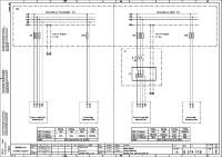
Note:The converter should be well earthed. The shielded cable is independently meant for speed feedback signal, with the shielded layer well earthed.
Note 1:Power line shall go into a magnetic ring,winding two turns in turn in the same direction and it will then be taken out in the same direction connecting to one side of a contactor. 1
2
3
康力电梯股份有限公司
设 计
单 位
工 艺
标准化
校 对
审 定
图 号
D10D610
审 核
日 期
页 号
1/23
VA01
图 名 SIEI Main circuit
4
A
2
1
4
3
X11 X12 X13
* Converter power is less than 37kw, canceling BKU KLS-MCU
QK1
D
KAP
RB
Y12
*
X21
L1 L2 L3
X22
0+
X23
3L2
KMC 2T1
4T2
R
R
C
S
T
S
+ + 3
T
JP9.1
Y13
Y14
Down
Y15
Y16
D
Y17
Enable Stage speed 1 Stage speed 2 Stage speed 3
JP9.2
JP9.3
JP9.4
JP9.5
JP9.6
B1 302
303
304
305
306
B2
307 TB2.30
301
13
VF+ 1KΩ
14
-
TB2.29
VF-
KAD
-
+
6T3
JP9.7
300
3 4
5L3
Up
BKU
0-
+ 0 0 1L1
Public end
RB
R4
323
S3
-
SN
S1
S2
S4
S5
S6
S7
SP SC
H1 H2 HC
AC
A1 C
UFC CIMR-LB4A****FAA CN5
U1
V1
IG IP
Z-
Z+
PG-X3 B-
B+
W
A-
V
FE
U
A+
TB1
TB2 a+ a- b+ b-
MC
MA
M5
M1
M6
E
M2
W1 COM
332
311
TYCH Note 1
6T3
U
V
B0
31
32
PG
KMY
W
+5V red
4T2
22
0V black
KMY
A+ blue
21
Z- yellow black
2T1
KMY
Z+ yellow
5L3 B- green black
3L2
B+ green
1L1
A- blue black
Brake resistunce and braking unit layout B
(TS5246N110)
OIH100-8192C/T-L3-5V
7.5KW Converter is fitted with 2KW36Ω one resistor 11KW Converter is fitted with 2KW54Ω two resistors(parallel) 15KW Converter is fitted with 2KW54Ω two resistors(parallel) 18.5KW conveter is fitted with 2KW72Ω three resistors(parallel) 22KW converter is fitted with 2KW90Ω four resistors(parallel) 30KW converter is fitted with 2KW90Ω four resistors(parallel)
A+ A- B+ B-
JP4.5
JP11.5 JP11.7 JP11.6 JP11.8
A+
A-
B+
Note 2
JP2.2 JP2.10
Public end Trouble
B-
X11
KLS-MCU
B
Preperation
X19
PE A
M
Note: The converter should be well earthed. The shielded cable is independently meant for speed feedback signal and speed given signal. Note 1: Power line should go into the magnetic ring in an identical direction, winding two turns in the same direction. It will then be taken out connecting to one side of a contactor. Note2: When the An Chuan L1000A converter is fitted with Xizi main machine, the coder should be Hai De Han 1321 coder, not changing number of wire.
1
2
3
康力电梯股份有限公司
设 计
单 位
工 艺
标准化
校 对
审 定
图 号
D10D610
审 核
日 期
页 号
02-1/23
VA01
图 名 L1000 sycn main circuit
4
A
2
1
4
3
X11 X12 X13
KLS-MCU RB
QK1
D
KAP
L1 L2 L3
*
X21 X22
0+
X23
0-
3L2
KMC 2T1
4T2
R
R
C
T
S
+ + 3
T
Down
JP9.1
302
Y14
Enable
JP9.2
303
304
Y15
Y16
Y17
JP9.4
JP9.5
JP9.6
D
Stage speed 1 Stage speed 2 Stage speed 3
JP9.3
305
306
307 TB2.30
301
13
R4
323
3
-
VF+
1KΩ
14
-
TB2.29
VF-
KAD
-
+
6T3
S
300
3 4
5L3
Y13
Up
JP9.7
BKU
+ 0 0 1L1
Y12
Public end
SC
S1
S2
BB
BB1
S5
S6
S7
AC
A1
RB
C
UFC CIMR-L7B TA1 U U1
V V1
W
PG-X2
2 3 4 5 6 7 8 9
TA2 1 2 3 4 5 6 7
MC
W1
310
MA 332
M1
E
M2
B1
B2
311
TYCH 1L1
3L2
5L3
2T1
4T2
6T3
*
Note1
Converter power is less than 18.5kw, canceling BKU
KMY
B
21
KMY
B
Brake resistunce and braking unit layout
22 0V +5V A+ A- B+
B0
31
7.5KW Converter is fitted with 2KW36Ω one resistor
B- Z+ Z-
11KW Converter is fitted with KW54Ω two resistors(parallel)
32 KMY
15KW Converter is fitted with 2KW54Ω two resistors(parallel)
U
V
W
PG
JP11.5 JP11.7 JP11.6 JP11.8
8192p/r
A+
A-
B+
B-
18.5KW conveter is fitted with 2KW72Ω three resistors(parallel)
KLS-MCU
JP4.5
JP2.2 JP2.10
Public end Trouble Preperation
22KW converter is fitted with 2KW90Ω four resistors(parallel) 30KW converter is fitted with 2KW90Ω four resistors(parallel) 22KW or more converter is fitted with CDNR-4030B braking unit
Note 2
PE
Note: The converter should be well earthed.
M
A
The shielded cable is independently meant for speed feedback signal and speed given signal,and the shielded layer should connected to an earthing end. Note 1: Power line should go into the magnetic ring in an identical direction, winding two turns in the same direction. It will then be taken out connecting to one side of a contactor. Note2:When the An Chuan L7B converter is fitted with Xizi main machine, the coder should be Hai De Han 1321 coder, not changing number of wire.
1
2
3
康力电梯股份有限公司
设 计
单 位
工 艺
标准化
校 对
审 定
图 号
审 核
日 期
页 号
VA01
图 名 An chuan L7B main circuit
4
D10D610 2/23
A
2
1
4
3
X11 X12 X13
KLS-MCU
QK1 D
Y12 Public end
KAP
Up
JP9.7
X21
L1 L2 L3
Y13
JP9.1
Y14
Y15
Y16
D
Y17
Down
Enable Stage speed 1 Stage speed 2 Stage speed 3
JP9.2
JP9.3
JP9.4
JP9.5
JP9.6
0-10V JP12.2
0V JP12.3
X22 X23 1L1
3L2
300
302
303
304
306
307
308
309
13
KMC
KAD
2T1
4T2
R
R
C
305
RB
5L3
6T3
S
14
T
S
323
COM
B
+ 2
T
DI7
DI8
DI9
DI3
DI4
DI5
AI1
0V C
UFC iAStar-S3M AS.T004 U U1
V V1
W
E
V+ 0V A+ A- B+ B- R+ R- C+ C- D+ D-
A1+
A1- B1+ B1-
E
K3A K3B K2B K2A
W1 310
332
311
TYCH Note 1 1L1
3L2
5L3
2T1
4T2
6T3
U
V
KMY
W
1b
D-
D+
5b 6b 2a 3b 5a 4b 4a 7b 1a 2b 7a 6a 5a 4a 3a 2a 1a
PCB socket
PE
C-
C+
R-
R+
32 KMY
B-
31
B+
B0
A-
22 A+
KMY
0V
21
B
+5V
B
7b 6b 5b 4b 3b 2b 1b
PG ERN1387
6a
JP11.6 JP11.5 JP11.8 JP11.7
A+
A-
B+
JP4.5
JP2.2 JP2.10
Public end Trouble operation
B-
KLS-MCU
M
A
Note: The converter should be well earthed. The shielded cable is independently meant for speed feedback signal and speed given signal. Note 1: Power line should go into the magnetic ring in an identical direction, winding two turns in the same direction. It will then be taken out connecting to one side of a contactor. 1
2
3
康力电梯股份有限公司
设 计
单 位
工 艺
标准化
校 对
审 定
图 号
审 核
日 期
页 号
VA01
图 名 iAStar sync main circuit
4
D10D610 3/23
A
2
1
4
3
TCO
FU5(3.15A)
B101
B111
UR2
QF2(6A)
~
01
Z01
-
D
D
C1
AC110V FU3(4A)
X21
110VDC
C2
BR1
KAS
3L2
Z02
+
~
02
4T2
101 C3
102
AC380V
KAS
5L3
104
6T3
201
X22 C
110VAC
GC3.1
220VAC
AC220V FU4(4A)
B202
B222
QF1(6A)
202
C
GC3.2
UR2 ~
-
01
Z01
C1
220VDC
C2
~
+
Z02
3L2
4T2
Note 1
02
KAS
B
B
201
L
202
N
+5V COM1 TPB +24V
QF3(4A)
COM
KDY 13
B24V
+24V
GC2.2
COM
GC2.1
14
*
PE A
* Wiring is made when the main mach has no mech brake releasing.
1
设 计
单 位
Note 1:When the band-type brake coil is DC 198 V,use the dotted line internal circuit. 工 艺
标准化
2
3
康力电梯股份有限公司 VA01
图 名
Control PS
校 对
审 定
图 号
D10D610
审 核
日 期
页 号 4
4/23
A
2
1
104
V6
4
3
GC1.1
GC1.2
GC1.3
Y8
GC1.4
+24V
COM
LD1 TXV+
TXV-
TXA+
TB2.31
TXA-
SM-11-A:JP1.5
D
Note2
JP6.5
JP7.6
JP7.3
JP13.1
JP13.2
JP13.3
JP13.4
Y2 lead-in
Y3
Y0
Y1
lead-out
band-type brake
strongly excited by the band-type brake
JP6.3
314
KMC
JP6.4
312
315
KMY
A1 A2
KMB
A1 A2
JP7.1
KM
KMB1 A1
A2
A2
9 TB2.32
Y4 front opening
323 A1
13
LD2
JP8.6
JP8.5 fire-control output Y11A C
JP6.2
JP6.1
5
313
JP7.7 JP7.8 pre-opening Y8
KLS-MCU
C
KLD 14 KLD
D
Y5
Y6
Y7
front closing
rear opening
rear closing
JP7.2
JP7.4
GM
KM1
JP7.5
GM1
B
B
316
RC3
RC1
RC6
6T3
RC2
KAD 5L3
Note 1
101
GC3.15
GC3.16
GC3.13
GC3.14
Note2 Note:1 Distribution wire used when strongly excited with the band-type brake. A
Note2: Distribution wire used when the opposite doors are installed.
1
2
3
康力电梯股份有限公司
设 计
单 位
工 艺
标准化
校 对
审 定
图 号
审 核
日 期
页 号
VA01
图 名 Main control panel output
4
D10D610 5/23
A
2
1
4
3
Note6
D
D
SQU
(53) GC2.3
PS GC5.11
GC5.12
1L1
GC5.16
90
111
113
84
86
Note7 KAS 2T1
PSS
(54)
+24V
GC5.15
88
GC8.2
GC8.1
PS
COM
GC5.17
SQD
CF
TB2.22
SSD
DC2.4
SSU
PX
Note1 SFI
GC2.4
SLDT
TB4.10
SLUT
TB4.9
SSD1
DC2.3
SSU1
SWFI
TB2.23
CF1
Note4
GC2.1 JP10.4
JP1.4
C
up forced change 1
JP10.3
JP1.5
X3
JP4.8
JP1.6
JP1.7
down forced change 1 up limit
X4
X5
X6
JP10.1 JP4.6
JP1.9
JP1.10
down forced change
X7
up leveling
X8
X9
JP2.1
JP2.3
down leveling
fire-cnotrol return
X10
JP3.2
C
fire-cnotrol operation
X12
X21
KLS-MCU
JP4.7 JP10.2
JP1.8
down limit up forced change
X13 safety relay INSP
JP2.4
X14 door lock relay INSP
X15
X16
lead-in INSP
lead-out INSP
JP2.6
JP2.5
X17
X22
band-type brake INSP
JP2.7
JP3.3
JP2.8
X23
X34
temp.INSP
back-up PS INSP
X32
band-type brake band-type brake SW INSP SW INSP 1
JP4.1
JP4.3
J3.4
X28 safety circuit V.
JP5.6
JP5.2
X29 door lock circuit V.
JP5.3
X30 hall lock circuit V.
JP5.4
B
KAS 14 (2T1)
1L1
KAD 2T1
331
3L2
KAD 4T2
350
53
KMC
13
KMY
54
5L3
KMB 14
352
351
6T3
3L2 KMB 4T2
354
355 TB2.35
(1L1) 13
322
TB2.17
321
TB2.18
JP4.5
B
SBZ 353
STD
HB
SBZ1 101
A
Note7 Note 1: Wire arrangement is made when there is the fire-control linkage. Otherwise short-connections are made to the corresponding number of wires without this function. Note 2 : Wiring made when the motor has temperature inspection functions. Note 3: It is used when fitted with a band-type brake inspection switch. Note 4: Wiring is made in case of the fire-control operation function. Note 5:It is used when there is the back-up power supply. Note 6: It needs to be installed when speed reaches and exceeds 1.7m/s . Note 7: When using the changshu Fuji contactors,please connect to a contact in the brackets. 1
2
Note3
Note2
3
120 GC3.12
Note5
118 GC5.10
康力电梯股份有限公司
设 计
单 位
工 艺
标准化
校 对
审 定
图 号
审 核
日 期
页 号
VA01
图 名 Main control board input
4
D10D610 6/23
A
2
1
4
3
D
D
KLS-MCU
C
SBPU
SBPD
SBTU
INS
JP1.1
INSP
GC2.5
80
JP1.2
Up
GC2.6
82
JP1.3
Down
C
SBTD
SSY
60
2
3
1
61
4
SAF B
B SRT
COM
78
GC2.1
GC2.7
control cabinet EMER electrically operated
car top INSP
A
1
2
3
康力电梯股份有限公司
设 计
单 位
工 艺
标准化
校 对
审 定
图 号
审 核
日 期
页 号
VA01
图 名
4
INSP and EMER electrically operated
D10D610 7/23
A
2
1
hoistway lighting
X11 Mach RM hoistway lighting SW
N
4
3
D
QF5
L2
L0
L1
SBM C
L
X11
N
QF4
Pit hoistway lighting SW
SRM
D
XSR 1
501
2
502
XS1 1
C
2
XS2
JN2
SHC
EL3
KAE DC9.1
ELA(NL)
1
9
504
EL1
SHT
ELA(NL-1)
1
HFN
JN1
SWN
JN3
1
2
2
B
B
SHL
JN4
EL2
ELA2
Note:NL=(total height of a hoistway -1)/6+1
A
ELA1
1
one hoistway lamp is each installed at a height of 0.5m from the hoistway botton and hoistway top.
2
3
设 计
单 位
工 艺
标准化
校 对 审 核
康力电梯股份有限公司 图 名
Lighting circuit
审 定
图 号
D10D610
日 期
页 号
VA01
4
8/23
A
2
1
4
3
Note3 Note2
Note4
Note
Note2
Note1 NC
JP3.1 JP3.2 JP3.3 JP3.4
JP8.05 JP7.06
JP7.05
JP5.08
JP5.07
SQE11
SWD
SWV
SBPS
SWCD
SWSW
SWMM
325
326
327
368
369
366
SBBC
D
SQE12
JP5.05
JP5.04
391
JP7.04
93
JP5.06
JP7.03
TB4.47
TB4.17
34
36
JP7.02 full load
DC10.5
381
DC10.4
TB4.16
39
front door front door rear door rear door front door rear door front door rear door overload opening in-place closing in-place opening in-place closing in-place light curtain light curtain safety shoes safety shoes
C
SSLL
C
TB4.15
38
DC10.7
CTB6.6
M8
DC10.11
CTB6.7
M9
DC10.12
CTB5.6
M6
DC10.3
M7
DC10.2
CMM
DC10.1
TB4.20
TXV+ TXV- TXA+ TXA-
CTB5.7
C
TB4.18
SLC1
SSFU
DC10.6
SLO1
DC9.9
SLC
SSOL
NC SQE2
TB4.53
SLO
SQE1
TB4.52
DC11.2 DC11.3 DC11.4
DC10.8
DC11.1
DC9.8
D
JP6.04 light load
JP6.03
JP6.02
JP6.01
attendant
special use
by-pass
JP7.01 NS-CB
JP5.03 NS-SW
367
JP5.02
JP5.01
pass word layer opening set sw maintain BUT
C
KLS-CCU up arrival gong
JP16.04
JP16.03
down arrival gong
JP16.06
JP16.05
lighting
JP16.02
fire-control light
JP15.1
JP16.01
JP15.4
buzzer
JP15.2
JP15.5
Opening BUT light
Opening BUT
JP10.1 JP10.2 JP10.3 JP10.4
closing BUT light
closing BUT
JP11.1 JP11.2 JP11.3 JP11.4
LH
DSS CMM DC10.1
B
HXF
DC10.9
B
DC10.10
JP1
13
KAE
HAB
SBOP
SBCL
UR1
KLS-ICU(JP9)
14
2
HOP
HAU 3
HCL
1
T24
TB4.19
38
A
JP8.02
1 2 3
201 202 PE
KLS-CCU
NC C
Note3: Wiring is made when the safety shoes are used. Note4: Wiring is made when the NS-CB function button is provided.
COM
JP8.01
* 1
Note1:Opening and closing in-place contacts should be located in door operator controllers. Note2: Wiring is made when using the opposite doors.
JP8.04 JP8.03
Note: The light load input signal should be short connected without a light load switch installed on.
2
wiring is made when the light curtain is used 3
康力电梯股份有限公司
设 计
单 位
工 艺
标准化
校 对
审 定
图 号
审 核
日 期
页 号
VA01
图 名
4
Car panel
D10D610 9/23
A
2
1
4
3
KLS-CCU(JP1) D
KLS-ICU
JP9
JP1 1
2
JP2
3
4
1
SBC1
C
JP10
2
JP8 3
4
1
SBC2
HC1
3
4
1
X3
2
X4
JP10
JP2
3
4
1
SBC9
HC8
VA-10-X X2
JP1
SBC8
HC2
X1
2
D
KLS-ICU
JP9
2
JP8 3
4
1
SBC10
3
4
SBC16
HC10
HC9
2
C
HC16
(VA-10-M-X)
X5
X6
X7
X8
COM
V24
V0 SPEAKER
JP9.1
JP9.2
JP9.3
D0
D1
D2
JP9.4
D3
JP9.5
JP9.6
JP9.7
D4
D5
D6
JP9.8
D7
S24V
JP9.10 +24V
V0
B
DC12.10
H8
DC12.9
H4
DC12.8
H2
DC12.7
H1
DC12.6
L8
DC12.5
L4
DC12.4
L2
DC12.3
L1
DC12.2
DC12.1
B
JP9.9 COM
KLS-CCU A
Note : When the audio reporting station is used ,if it is a building of 20 stories or above ,the VA-10-M-X will be used. 1
2
3
设 计
单 位
工 艺
标准化
校 对 审 核
康力电梯股份有限公司 图 名
Command panel/ audio reporting station
审 定
图 号
D10D610
日 期
页 号
10/23
VA01
4
A
2
1
4
3
D
D
JP2
JP2
4 LED
INSP
INSP
JP3
HD(n)
JP3
HD(2)
full load
3
SBD(2)
3
3
JP1
1 2 3 4
1 2 3 4
4
4
4 JP4
C
2
2
2 SBD(n)
JP3 1
1
full load
SBU(1)
3
LED INSP
1
1 2 3 4
2
4
4 LED full load
JP1
SBU(2)
3
3
C
KLS-DCU-VS/P
2
2
KLS-DCU-VS/P
HU(1)
1
1
1
KLS-DCU-VS/P
JP2
HU(2)
JP4
JP4
JP1
1 2 3 4
1 2 3 4
1 2 3 4
SRK
GC4.4 GC4.3 GC4.2
GC4.1
B
TXV+
B
Home floor lift-lock SW
TXVTXA+ TXA-
Note: Connections across s1.2 and s1.3 are made to set an address code on the display panels. The S2.1, S2.2, S3.1 and S3.2 are the serial comm terminal resistance jumpers, at the same time, shorting is made to show connecting to the built-in 120 Ω resistance. A
1
2
3
康力电梯股份有限公司
设 计
单 位
工 艺
标准化
校 对
审 定
图 号
审 核
日 期
页 号
VA01
图 名 Transversal display call
4
D10D610 11-1/23
A
2
1
4
3
HU2
1 2
JP3
2
2
JP3
1
1
D
HU1
JP3
SBU2
SBU1
3
3
3
4
4
4 HD(n)
HD2
1
1
1
2
2
2 SBD(n)
JP4
D
SBD2
JP4
JP4 3
3
3
4
4
4
C
C
KLS-DCU
KLS-DCU
INSP
INSP
LED
INSP
LED
LED
full load
SW1
2
3
4
full load
ON
ON
1 2
1 2
SW1
OFF
JP2 1
KLS-DCU
1
JP5 2
3
4
1
2
ON SW1
OFF
JP2 3
4
full load
1
JP5 2
OFF
JP2 3
4
1
2
1 2
3
4
1
JP5 2
3
4
B
B
GC4.1
TXV+
GC4.2
TXV-
GC4.3
TXA+
GC4.4
TXA-
SRK Home floor lift-lock SW
A
1
2
3
康力电梯股份有限公司
设 计
单 位
工 艺
标准化
校 对
审 定
图 号
D10D610
审 核
日 期
页 号
11/23
VA01
图 名 Transversal display call
4
A
2
1
D
KLS-MCU lift A
4
3
JP14.2
TXV-
JP14.2
JP14.3
CB+
JP14.3
JP14.4
CB-
JP14.4
D
KLS-MCU lift B
JP13.2 JP13.4 JP13.1 JP13.3
JP13.2 JP13.4 JP13.1 JP13.3
TXV+ TXV- TXA+ TXA-
TXV+ TXV- TXA+ TXA-
C
C
1
2 3 JP2
4 1
1 1
HU(n)
2
2
3
3
JP3 B
KLS-DCU
JP4
3 JP2
4
JP3 SBU(n)
4
4
1
1
HD(n)
2
2
3
3
B
KLS-DCU JP4
SBD(n)
4
4
A
1
2
2
3
康力电梯股份有限公司
设 计
单 位
工 艺
标准化
校 对
审 定
图 名 Parallel wiring diagram 图 号 D10D610
审 核
日 期
页 号
VA01
4
12/23
A
4
3
DWP
1140
140
STL GC5.7
Pit safety SW/INSP SW
DC9.5
11
TB4.40
car top safety SW
SRT
SSCL
134
TB4.37
car safety SW
DC3.8
STT
132
DC3.7 DC9.4
A10 GC3.8
Mech lock SW
D
12
152
TB4.38
KMB1 1L1 2T1
TB4.39
R
Note 1
Counterweight safety gear SW
Governor SW
Counterweight governor SW
11
KAP
14
GC6.8
TB2.7
GC5.8
Up ultimate SW
138
137
SSCB
SSAN
135
Down Counterweight buffer Car buffer ultimate SW
STP
115
Phase failure
C
139
SSBB
GC5.6
GC3.10
TB4.41
D
Safety gear SW
KAS A1 A2
120
Mach EMER stop
RC4
C
2T1 330
GC3.12
ZQ2
GC6.9
SLDL
332
TB2.8
SLUL
114
1L1
TB2.9
100W50Ω
1511 SSLS
SSLS1
1121
KMB
112
TB2.6 GC3.7
Pit safety SW
SAF
Note 1 SSAN1
STC
110
GC3.11
SMH(n-1)
3MT
nMT
SMHn
GC5.9
KAD
118
A1 A2 RC5
GC5.10
201
Note 6 44
328
B
(63) 13
KMC
329
43
44 KAD
330
2T1
1L1
ZQ1
ZQ2
TB2.1
KMB
13
TB2.2
14
Note 6
KMB
B
328
KMY
(64) 14
(64) 14
43
KMC (63) 13
202
329
43
TB4.36
SMH2
2MT
44
SMH1
116
KAD
SMC
YBK1
broken step chain device 1
SBAD
YBK
broken step chain device
1136
14
GC5.5
SSRG1
Note 1
334
TB2.5
136
Pit maintenance safety SW
KMB
SSRG
133 D
Note 1
13 333
Note 1
201
101
102
ZQ1
2
1
44
Note 2 YBK1
43
YBK
KMY
Note 3
Note 4 A
Note 6 43
44 KMY
328
(64) 14 KMC
(63) 13
01
UR3
329
43
44 KAD
330
2T1 KMB
1L1
ZQ1
YBK
YBK1
TB2.1
202
02
ZQ2 TB2.2
13
1
2
Note 5:wiring is made when strong excitation
14
is conducted with a band-type brake.
KMB
Note 1: the corresponding line number's wires should be short connected without SW setting in a dotted line. Note 2: the electric circuit in the dotted line lies in a junction BX of the brake. Note 3: the electric circuit in the dotted line is used only when the AC220v band-type brake sync main mach is introduced. Note 4: the electric circuit in the dotted line is used only when DC198V band-type brake sync main mach or DC110V band-type brake sync main mach or DC110V band-type brake async main mach is introduced. Notes 6:connections are made to the contacts in the backet when Changshu Fuji contactors are used.
3
Note 5
康力电梯股份有限公司
设 计
单 位
工 艺
标准化
图 名
safety, braking
校 对
审 定
图 号
D10D610
审 核
日 期
页 号
13/23
VA01
4
A
2
1
4
3
202
L
PE
N
XK1
4
XK2
3
XK3
CTB5.5
door-opening speed-limiting
201
D
CTB5.9 door-opening in-place
CTB5.2
door-closing in-place
CTB5.1
door-closing speed-limiting
Car top junction BX socket
7
V
W
Branch cable CDB5 plug
CTB5.4
Car top branch cable CDB5
XK4
V6
KM
GM
(1#)
(2#)
(3#)
8
6
1
Car top junction BX
RVV(8*0.75+1*2.0)
Pin NO.
DWG line NO. cable line NO.
connector NO.
2
VF-SL
Door operator
U
CTB5.3
C2
C3
A3
CMM
M6
(4#)
C
CTB5
M7
(6#)
CTB5.8
MDO
A2
(5#)
CTB5.6
CTB5.7
D
L=3m Door operator controller terminal terminal line NO. SER NO.
signal name
1
201
1
L
201
2
202
2
N
202
3
KM
3
1
KM
4
GM
4
2
GM
5
V6
5
8
V6
6
M6
6
A3
M6
7
M7
7
A2
M7
8
CMM
8
C2、C3
CMM
output public end
9
PE
G
PE
PE
earthing wire
controller PS
opening control signal closing control signal control signal public end
closing limit output opening limit output C
to operation BX CZB panels
PE
B
L
PE
N
4
XK1
3
XK2
XK3
door-opening speed-limiting
202
door-opening in-place
201
CTB6.9 door-closing in-place
CTB6.2
door-closing speed-limiting
Car top junction BX socket CTB6.1
7
CTB6.5
V
W
CTB6.4
Branch cable CDB5 plug
Car top branch cable CDB6
XK4
V6
KM1
(1#)
GM1
(2#)
Car top junction BX
8
6
1
1
2
VF-SL C2
C3
A3
A2
CTB6
MDO
CMM
M8
M9
(4#)
(6#)
(5#)
CTB6.8
CTB6.6
CTB6.7
to operation BX CZB panels
PE
pin NO.
cable line NO.
terminal SER NO.
terminal line NO.
201
1
L
201
signal name B controller PS
202
2
N
202
3
KM1
3
1
KM1
4
GM1
4
2
GM1
5
V6
5
8
V6
control signal public end
6
M8
6
A3
M8
7
M9
7
A2
M9
closing limit output opening limit output
8
CMM
8
C2、C3
CMM
output public end
9
PE
G
PE
PE
earthing wire
Note: the electric circuit in the dotted line is used in case of an opposite door.
2
door operator controller
DWG line NO.
2
A
1
L=3m
RVV(8*0.75+1*2.0)
(3#) connector NO.
door operator
U
CTB6.3
3
设 计
单 位
工 艺
标准化
校 对 审 核
opening control signal closing control signal
康力电梯股份有限公司 VA01
图 名
Door operator
审 定
图 号
D10D610
日 期
页 号
14/23
4
A
2
1
4
3
car top junction BX socket
PE
CTB5.3
CTB5.4
CTB5.5
branch cable CDB5 plug
CTB5.9
D
CTB5.2
202
CTB5.1
201
car top branch cable KM
GM
(2#)
220
N
X10
X4
door operator
V6
(3#)
I1
PE
car top junction BX
(1#)
I2
COM
ECO
O1
NC
O2
NC
C
MDO
PE
CMM coder
door-closing in-place
M
door-opening in-place
public end
CTB5
M7
(4#)
M6
(5#)
CTB5.8
(6#)
CTB5.7
L=3m
D
door operator controller
DWG line NO.
cable line NO.
terminal SER NO.
terminal line NO.
1
201
1
1
201
2
202
2
2
202
3
KM
3
4
KM
4
GM
4
5
GM
5
V6
5
11
V6
6
M6
6
19
M6
7
M7
7
13
M7
8
CMM
8
12、18
CMM
9
PE
G
3
PE
pin NO.
connector NO.
CDB5
RVV(8*0.75+1*2.0)
signal name controller PS opening control signal closing control signal control signal public end closing limit output opening limit output output public end
C
earthing wire
CTB5.6
to operation KLS-CCU panels
car top junction BX socket
PE
CTB6.3
CTB6.4
car top branch cable CDB6 KM1
GM1
(2#) B
MD1 coder
terminal SER NO.
terminal line NO.
1
201
1
1
201
2
202
2
2
202
3
KM1
3
4
KM1
4
GM1
4
5
GM1
5
V6
5
11
V6
6
M8
6
19
M8
7
M9
7
13
M9
M8
8
CMM
8
12、18
CMM
(6#)
9
PE
G
3
PE
COM
ECO
CMM (4#)
NC
O2
NC
CTB6
door-closing in-place
O1
M9 (5#)
door operator controller
cable line NO.
pin NO.
connector NO.
CTB6.6
M
PE
door operator
door-opening in-place
X10
RVV(8*0.75+1*2.0)
L=3m
DWG line NO.
(1#)
I2
CTB6.7
X4
car top junction BX
V6
(3#)
I1
PE
public end
N
CTB6.8
220
branch cable CDB6 plug
CTB6.5
CTB6.9
CTB6.2
202
CTB6.1
201
signal name B controller PS opening control signal closing control signal control signal public end closing limit output opening limit output output public end earthing wire
to operation KLS-CCU panels A
Note: the electric circuit in the dotted line is used in case of an opposite door
1
2
3
康力电梯股份有限公司
设 计
单 位
工 艺
标准化
校 对
审 定
图 号
D10D610
审 核
日 期
页 号
15/23
VA01
图 名 ECO door operator
4
A
2
D
LA
NKT12(1-1)A
PHO-M1 control cabinet main mach
4
3
R
R
Y
L
L
P+
+
+
N-
-
-
HAA
NKT12(1-1)A
1
PHO-M2
D
monitor room main mach
811 SBB
YJ
P4
7 C
501
1
502
2
4
3
RKP220/12
-
+
L
R
NKT12(1-1)-A
-
+
L
R
-
NKT12(1-1)-A
+
L
R
EB1 SBB1
NKT12(1-1)B EB2
YJDY EMER PS
PHO-T
PHO-B
car top main mach
pit main mach
C
Note: intercom sub-mach PHO-S is installed in an operation BX; PHO-M1 is installed in mach room;
PHO-S
PHO-M2 is installed in monitor room;
car accessory mach
PHO-B is installed in the pit; PHO-T is installed in car top; YJDY EMER PS and HAA alarm bell are installed on car top;
Four-wire system five-party communication by phone
YJ EMER light is installed near the ceiling in the car; SBB alarm bell button and SBB1 intercom button are installed on the operation BX panels.
LA
control cabinet main mach
2
Y
1
1
P+
S1
S1
N-
S2
KP-SG01
KP-SG01
2
PHO-M1
PHO-M2
S2
B
B HAA
monitor room main mach
811 SBB
YJ
P4
7 501
1
502
2
4 RKP220/12
1
2
1
2
KP-SG01
KP-SG01
PHO-T
PHO-B
1
2
EB1 SBB1
NBT12(1-1)B EB2
YJDY
A
3
EMER PS
car top accessory mach
pit accessory mach
PHO-S car accessory mach
Double-wire system five-party communication by phone
1
2
3
康力电梯股份有限公司
设 计
单 位
工 艺
标准化
校 对
审 定
图 号
D10D610
审 核
日 期
页 号
16/23
VA01
图 名
4
Five-party communication by phone
A
2
1
4
3
KP-SG01 NBT12(1-1)B KP-SG01 D
RKP 220/12 L
S1 S2
N
PS +12
car sub-set 1
sub-set 2
sub-set 3
sub-set 4 D
L
-12
1
N
2
1
2
1
2
1
2
1 2
control console PS
main phone set 1
1 2 +12 -12
3
KP-SG01 NBT12(1-1)B
4
6
collective selector C
S1
7
S2
+12
L
S2
-12
N
1
2
sub-set 2 1
2
sub-set 3 1
sub-set 4
2
1
2 C
2
9
phone set
car sub-set 1
S1
1
8 control console
PS
KP-SG01
5 signal
main phone set 2
10 N
KP-SG02
KP-SG01
B
B
NBT12(1-1)B KP-SG01
PS
car sub-set 1
S1
+12
L
S2
-12
N
1
2
sub-set 2 1
2
sub-set 3 1
sub-set 4
2
1
2
1 2
main phone set N
A
wiring diagram for multiple sets of lift phones collective control
1
2
3
设 计
单 位
工 艺
标准化
校 对 审 核
康力电梯股份有限公司 VA01
图 名
Collective selection intercom
审 定
图 号
D10D610
日 期
页 号
17/23
4
A
2
1
COM
SQU
(62) 22 Note 2
D
KAS
PS
GC2.3
PSS
1L1 2T1 (53) (54)
ELJ
KAS
21 (61)
N-
DC2.3
ELZ
FMQ
Componet code
STP
Z31
+24V
L1
SDY
KLS-MCU(J1.10)
Note 2
P+
EMER rescue circuit
TB2.28
SSY
4
3
SFW
L2
YDZ
L21
GC6.1
CMM
GC6.11
SDY SFW
L3
GC2.12
GC6.12
safety relay
control cabinet
SQU
up leveling SW
car
STP
control cabinet quick-stop SW
control cabinet
ELJ
leveling indicating lamp
control cabinet
ELZ
rescue lamp
Hoistway
FMQ
leveling buzzer
control cabinet
governor test SW
control cabinet
SSY
Governor test circuit
C
car governor test SW
control cabinet
counterweight governor test changeover SW
control cabinet
SSY
+24V
L1
SDY
SFW
L2
L21
YDZ
SDY
car governor actuating BUT
control cabinet
SFW
car governor reset BUT
control cabinet
Car governor test circuit
CMM SDY
YDZ
car governor actuating coil
car governor
SFW
L3
SSY1 B
L13
SDY1
SFW1
L23
L22
YFM
car governor reset coil
car governor
L213
SDY1 SFW1
L33
L223
YFW
YDZ1
YFW1
Counterweight governor test circuit
Note 1
Z11
X11
1
KDY
Z12
9
SJK
Z13
SKZ
D
Note 1
C
SSY1 SSY2
Installation position
KAS
SSY2
YFW
L22
Name
SDY1
counterweight governor actuating BUT
SFW1
Note 1
control cabinet
Note 1
counterweight governor reset BUT
control cabinet
Note 1
YDZ1
counterweight governor actuating coil
counterweight governor
Note 1
YFM1
counterweight governor reset coil
counterweight governor
Note 1
UPS
rescue PS
Hoistway
KDY
PS relay
control cabinet
SJK
brake-releasing SW
control cabinet
SKZ
brake-releasing BUT
control cabinet
B
Notes: the circuit in the dotted line is used without mach brake-releasing device.
ZQ1
TB2.3
Notes 1: the circuit in the dotted line is used when the counterweight governor is increased. Notes 2: connections are made to the contacts in the bracket when Changshu Fuji contacts are used.
UPS A
Z21
N
2
KDY
Z22
10
SJK
Z23
SKZ
ZQ2
TB2.4
Note
Power brake-releasing circuit
1
2
3
设 计
单 位
工 艺
标准化
校 对 审 核
康力电梯股份有限公司 VA01
图 名
EMER rescue
审 定
图 号
D10D610
日 期
页 号
18/23
4
A
2
1
4
3
ON
D
TXA-
JP2.4
TXA+
JP2.3
TXV-
JP2.2
TXV+
JP2.1
ON
SW1 J3.1 J3.2 J5.1 J5.2
KLS-EXT
KZB
1 2
arrival gong public end up direction down direction
PL2
PL3
PL4
public end
PL5
JP4.1
JP4.2
JP4.3
JP4.4
JP4.5
JP4.6
PL2
JP3
OFF
PL1
PL1
JP1
PL3
PL4
CO
PL5
JP4.7
UPB
JP4.8
DNB
JP4.9
DZZ
J3.1 J3.2 J5.1 J5.2
operation
JP4.10
stop
Y0
CO
1 2
SW1
MVB
Y1
BST
KLS-EXT1
KZB1
D
OFF
door lock trouble Y2
DOB
public end Auto operation
Y3
EOB
COM1
CO
Y4
BAU
INSP
overload
Y5
JX
fullload public end
Y6
CZ
Y7
MZ
COM2
CO
C
C
PL5
PL4
PL3
PL2
PL1
CO
UPB
DNB
MVB
BST
DOB
EOB
BAU
JX
CZ
MZ
1
2
3
4
5
6
7
8
9
10
11
12
13
14
15
16
Note
TB3 control cabinet terminal strip
BAS(Building Automation System) function description:
B
1、 PL1-PL5 floors are fitted with binary system signal. PL1 stands for low level, PL5 stands for high level,00001is ground floor;arrangement in ascending order is in turn made in accordance with physical floors(not per the displayed floors) 2、UPB will show to go up and up signal. In case of stop, it displays UP; In case of up, it displays ON;In case of stop and without up, it displays OFF. 3、 DNB will show down and down signal.In case of stop, it displays DOWN; in case of down, it displays ON; in case of stop and without down,it displays OFF. 4、 BAU will show full-auto operation signal.In case of full -auto operation, it displays ON; in case of other operation, it displays OFF. 5、 BST will show stop signal. In case of stop(including relevel), it displays ON; in case of start, it displays OFF. 6、 DOB will show the car door condition signal. In case of door opening(without door lock signal), it displays ON; in case of door closing(with door lock signal), it displays OFF. 7、 EOB will show trouble signal. Due to failure, the lift will stop running, it displays ON; when trouble is cleared, it displays OFF. 8、 MVB will show operation signal. In case of stop(regardless of up or down),this signal will show OFF;when running(regardless of up or down), this signal will show ON. 9、 DZZ will show arrival gong signal. In case of arrival, the signal displays ON; in addition, it displays OFF. 10、 JX will show INSP signal. when an elevator is in INSP condition, the signal dispalys ON; in addition, it displays OFF. 11、 CZ will show overload signal.when an elevator is in overload condition, ,the signal displays ON;when it is not in overload condition, it displays OFF. 12、 MZ will show full load signal. when an elevator is in full load condition, it displays ON; when it is not in full load condition, it displays OFF.
B
Note:When selecting BAS function, the control cabinet needs to increaseTB3 terminal strips. Note:When 2 connects with 1 for J3 and 2 connects with 1 for J5 are low level and effective;when 2 connects with3 for J3 and 2 connects with 3 for J5 are high level and effective. A
1
2
3
康力电梯股份有限公司
设 计
单 位
工 艺
标准化
图 名
BAS circuit
校 对
审 定
图 号
D10D610
审 核
日 期
页 号
19/23
VA01
4
A
2
1
4
3
QTRONICS 2500 POWER D
D
ALARM
TROUBLE
Latching Non-Latching Normal/Closed Normal/Open Normal/Closed Normal/Open
Normal/Open
Latching Normal/Closed
356
COM
TB2.34 TB2.33
KLS-MCU
JP4.4 X35
C
+24v
JP4.6
C
Wiring is made according to this DWG when there is some seismic function. 120
118
COM
X20
JP4
JP3
1 B
2
1
2
SM-11-A 1
JP3.1
2
3
4
B
KLS-MCU 5
1
2
JP1
JP2
X18
JP2.9
Y8
JP7.7
GC3.20 DC3.20
GC3.19
MQD
DC3.19
DC2.2
GC2.2
MQU
SMU
SMD
A
Door-pre-opening and micro leveling panel COM
1
+24V
COM
2
3
康力电梯股份有限公司
设 计
单 位
工 艺
标准化
校 对
审 定
图 号
D10D610
审 核
日 期
页 号
20/23
VA01
图 名
4
Door-pre-opening and relevel
A
2
1
4
3
weighting controller
DTZZⅢ-SK D
D
X2
X1
CMM 93
34
VF+ VF- 201 202 110 1121 36
L21 L22 PE
GC6.4 VF+
1
current+
24V+
1
2
current-
24V-
2
3
void
direction+ 3
4
void
direction-
5
void
door lock+ 5
GC6.5
7
void
2
3
4
5
6
7
8
9
10
11
12
4
door lock- 6
void
leveling+ 7
GC6.2 93
9
C
leveling- 8
8
overload
void
9
void
10
GC6.1 CMM
10
RH11
GC6.3 34
11 12
full load
13
GC6.6
GC6.10 36
201
14 15
172347-1
G
control cabinet down(total height of a hoistway+8m)
6
1
control cabinet up(10M)
VF-
light load
16
GC6.7
GC6
control cabinet socket
171358-1
cable RH11 plug
GC6
weighting cable RH11 control cabinet RVV(12*0.75+1*2.0) connector DWG line connector cable pin NO. NO. line NO. NO.
GC6
202
B
weighting & governor device terminal line NO.
explaination public end
1
CMM
1
CMM
2
93
2
93
overload
3
34
3
34
fullload
device
C weighting compensating device
4
VF+
4
VF+
5
VF-
5
VF-
6
201
6
201
7
202
7
202
8
110
8
110
9
1121
9
1121
10
36
10
36
11
L21
11
L21
actuating coil
12
L22
12
L22
reset coil
13
PE
G
signal
PS
safety light load governor testing
ground wire
B
sensor cable CMM
93
34 VF+ VF- 201 202 110 1121 36
L21 L22 PE
pressure sensor
Notes: Pressure sensors are installed in the rope end plate on the side of a car. Weighting controllers are installed near the pressure sensors, not more than 10m. The input/output signal from a control cabinet is connected with the control cabinet via the hoistway cable RH11(RVV(12*0.75+1*2.0)) A
Resistor R4 is installed in the control cabinet.
1
2
3
康力电梯股份有限公司
设 计
单 位
工 艺
标准化
校 对
审 定
图 号
D10D610
审 核
日 期
页 号
21/23
VA01
图 名 SK type weighting circuit
4
A
2
1
4
3
up ultimate SLUL
220
up limit SLUT
magnet vane
D
D
SLUL SLUT SSU
up forced change SSU
Top floor
SSU1
up forced change SSU1 down leveling SW SQD up door zone SW SMU
180
down door zone SW SMD
C
C
up leveling SW SQU
Note1: down forced change1 SSD1
car
down forced change SSD
B
SSD
SLDT SSDL
B
car
SSD1
down limit SLDT
down ultimate SLDL
SSU\SSD 900-1000 1300-1400 2400-2500
lift speed
0.63m/s 1.0m/s 1.75m/s
ground floor
A
Notes:1、 When SW actuating. the hoistway SW installation position should be the distance from the car sill to top floor (or GND floor) landing door sill. 2、 The up door zone SW SMU and the down door zone SW SMD are used only when pre-opening or relevel functions are selected. Note1: it is used when speed exceeds 1.75m/s. 1
2
3
SSU1\SSD1
SLUT\SLDT
SLUL\SLDL
30-50
130
3800-4200
设 计
单 位
工 艺
标准化
校 对 审 核
康力电梯股份有限公司 VA01
图 名
Hoistway information
审 定
图 号
D10D610
日 期
页 号
22/23
4
A
Small terminal strip
TB1
TB2
SER NO.
line NO.
1 2 3 4 5 6 7 8 9
X11 X12 X13 N PE PE U V W
D
position
Small terminal strip
C
TB2 SER NO.
B
1 2 3 4 5 6 7 8 9 10 11 12 13 14 15 16 17
line NO.
ZQ1 ZQ2 Z11 Z21 102 110 114 1121 112 135 116 118 120
position band-type brake coil
UPS broken rope SW pit, car safety governor, up ultimate counterweight safety gear governor car buffer, safety gear door lock door lock door lock
stand-by 1
COM COM 352
Trailing comm cable C00
common line common line band-type brake INSP
SER NO. line NO.
18 19 20 21 22 23 24 25 26 27 28 29 30 31 32 33 34 35 36 37 38 39 40 41 42 43 44 45 46 47
354 111 113 78 CF CF1 P+ N- LA Y Z31 VF+ VFLD1 LD2 +24V 356 355
GC1 position
SER NO.
line NO.
Temp. INSP
1 2 3 4 5
TXV+ TXV- TXA+ TXA- PE
up limit down limit INSP fire-control fire-control linkage
plug:1-480763-0 five-party comm by phone
Trailing comm cable C00
GC2 line NO.
1 2 3 4 5 6 7 8 9 10 11 12 13
COM +24V PS PX 80 82 78 P+ N- LA Y CMM 93
position
rescue lighting weighting compensation fire-control output seismograph PS seismic INSP back-up PS INSP
stand-by 2
L0 L1 L N 201 202
socket:1-480764-0
SER NO.
hoistway lighting
stand-by 3
501 502 PE PE
GC4
GC3 position
socket:172347-1 plug:171358-1
SER NO.
line NO.
1 2 3 4 5 6 7 8 9 10 11 12 13 14 15 16 17 18 19 20 21
201 202 501 502
position
stand-by
SER NO.
line NO.
1 2 3 4 5
TXV+ TXV- TXA+ TXA- PE
socket:171830-1 plug:171364-1
1 2 3 4 5 6 7 8 9 10 11 12 13
Hoistway cable
GC5 SER NO.
line NO.
1 2 3 4 5 6 7 8 9 10 11 12 13 14 15 16 17 18 19 20 21
501 502
position
stand-by
133 135 110 114 116 118 84 86 88 90 111 113 CF COM PE
Note 3: This point is used as light load without pre-opening doors.
3
line NO.
Hoistway cable R01
GC8 position
CMM 93 34 VF+ VF- 201 202 114 1121 36 L21 L22 PE
SER NO.
1 2 3 4 5 6 7 8 9 10 11 12
line NO.
P+ NLA Y
position D
C
socket:1-480709-0
socket:172347-1
stand-by
Note 2: when it has group supervision functions,line NO.s on GC4 insert can respectively be changed into CANV1+、CANV1-、CANA1+、CANA1-、PE.
2
SER NO.
plug:1-480763-0
A
1
position
Note 2
stand-by
135 116 120 KM1 GM1 KM GM V6 PE MQU(36) Note 3 MQD 34
GC6
socket:1-480764-0
stand-by
110 A10
Weighting & governor cable
Call comm cable R03
Trailing comm cable C00
by phone
PS terminal
4
3
five-party comm
2
1
plug:1-480708-0
plug:171358-1
B
Note 1:
Note1:It is used when speed exceeds 1.75m/s or above.
socket:171830-1 plug:171364-1
康力电梯股份有限公司
设 计
单 位
工 艺
标准化
校 对
审 定
图 号
D10D610
审 核
日 期
页 号
23/23
VA01
图 名 connectors arrangement
4
A
2
1
4
3
D
D
control cabinet
C
C
L1 R00 N1 wiring terminals car top wiring BX
B
B
Note:When air conditioner is used, two large terminals will be added to a control cabinet,directly providing AC 220V PS.One trailing round cable RVV(4*1.5) will be added and one three-hole socket AC30-3x16A will be added to the wiring BX of a car top.
A
1
2
3
设 计
单 位
工 艺
标准化
校 对 审 核
康力电梯股份有限公司 图 名
Selecting air conditioning function
审 定
图 号
D10D610
日 期
页 号
VA01
4
attachment 3
A
2
1
4
3
D
D
Dingli outage EMER rescue device SARD-INVERTER (3*AC380V)
5
4
3
13
14
6
5
43
44
PC1
NC NO
PC2
H L
D S
D S
BZSZ1
PCSZ1
PCSZ2
6
7
yellow line
blue line
red line
1
2
3
4
5
6
C
black line
+24V
Note 1
X01 X02 X03
PTA2
8
JXX2
5
JXX1
4
JXS2
PC2-
3
JXS1
PC2+
2
JX2
PC1-
1
JX1
PC1+
PTA1
T
JX-
S
JX+
R
BZ-
BZ+
A2
L1 L2 L3
C
6
1
JX1
R KM
A1
BZ1
W
JXXR1
22
C
V
JXSR1
K1
KM
K1
U
JXR1/1
1 2 3 4 5
2 21
PTC3
PTB1
SARD-CHARGE
X11 X12 X13
YJS
COM
YJK
COM
B
B
JP8.3
JP8.1 Y9
JP4.5
EMER leveling completion signal
JP4.2 X33
EMER auto leveling operation input
Note 1: When there is an outage EMER device, X01、X02 and X03 are the power line PS lead-in wire.
KLS-MCU
A
1
2
3
康力电梯股份有限公司
设 计
单 位
工 艺
标准化
校 对
审 定
图 号
D10D610
审 核
日 期
页 号
attachment 4
VA01
图 名
4
Dingli EMER rescue device
A
2
1
4
3
D
1
2
3
4
5
24V+
GND
JDQ-1
JDQ-2
6
7
8
XF-1
XF-2
floor selective controller1#
IC card controller
controller interface
floor selector interface
DTIC
card reader interface
card reader
controller interface
D
controller interface
SBC(n)
TB4.20
nth floor comm.BUT
TB4.19
Password key board
HC(n)
T24
floor selective controller2#
C
controller interface
C
CMM
B
B
4
3
2
1
JP(n)
KLS-ICU
Note 1
Note 1: The circuit in the dotted line is used only when a single floor is controlled. Floor selective controllers are added to it when more than two floors are controlled.
wiring is made when IC card functions are selected
For floor selective controller wiring see its wiring diagram. A
1
2
3
设 计
单 位
工 艺
标准化
校 对 审 核
康力电梯股份有限公司 图 名
IC card control system diagram
审 定
图 号
D10D610
日 期
页 号
attachment 2
VA01
4
A
2
1
4
3
J10
KLS-ICU D
D
JP1 1
2
JP2 3
4
1
2
JP3
3
SBC1
4
1
2
3
SBC2
HC1
JP4 4
1
2
3
SBC3
HC2
JP5 4
1
2
3
SBC4
HC3
JP6 4
1
2
3
SBC5
HC4
JP7 4
1
2
3
SBC6
HC5
JP8 4
1
2
3
SBC7
HC6
4
SBC8
HC7
HC8
C
C 1
2
3
1
2
Group 01
3
1
2
Group 02
3
1
2
Group 03
3
1
2
Group 04
3
1
2
Group 05
3
1
2
Group 06
3
Group 07
floor selective controller 1#
floor selective controller 2 # Group 07 3
Group 06
2
1
3
B
Group 05
2
1
3
HC16
3
2
1
3
4
2
1
1
3
4
JE7
2
1
3
1
4
JE6
2
1
1
3
4
JE5
2
1
1
3
4
2
1
JE3
1
HC9
SBC10
3
JE4
2
HC10
SBC11
3
Group 08
2
HC11
SBC12
3
Group 01
2
HC12
SBC13
3
Group 02
2
HC13
SBC14
3
Group 03
2
HC14
SBC15
JE8
1
HC15
SBC16
4
Group 04
2
4
SBC9
3
2
1
4
3
JE2
2
1
JE1 J9
KLS-ICU A
康力电梯股份有限公司
Note :Control ends for selector controllers will be wired in turn according to actual stops sequence,without void ends in the middle and control on the ground floor. 设 计
单 位
Note 1: If a single lift only controls single floors,the selector controllers will be removed.
工 艺
标准化
Note 2: XF-1 and XF-2 of DTIC controllers will be short wired.
校 对
审 定
图 名 IC card selector wiring 图 号 D10D610
审 核
日 期
页 号
1
2
B
3
VA01
4
attachment 1
A